EP2447634B1 - Refrigerator and dehumidification control method thereof - Google Patents
Refrigerator and dehumidification control method thereof Download PDFInfo
- Publication number
- EP2447634B1 EP2447634B1 EP11186279.3A EP11186279A EP2447634B1 EP 2447634 B1 EP2447634 B1 EP 2447634B1 EP 11186279 A EP11186279 A EP 11186279A EP 2447634 B1 EP2447634 B1 EP 2447634B1
- Authority
- EP
- European Patent Office
- Prior art keywords
- refrigerating compartment
- dehumidification
- cooling
- heating
- fan
- Prior art date
- Legal status (The legal status is an assumption and is not a legal conclusion. Google has not performed a legal analysis and makes no representation as to the accuracy of the status listed.)
- Active
Links
Images


Classifications
-
- F—MECHANICAL ENGINEERING; LIGHTING; HEATING; WEAPONS; BLASTING
- F25—REFRIGERATION OR COOLING; COMBINED HEATING AND REFRIGERATION SYSTEMS; HEAT PUMP SYSTEMS; MANUFACTURE OR STORAGE OF ICE; LIQUEFACTION SOLIDIFICATION OF GASES
- F25D—REFRIGERATORS; COLD ROOMS; ICE-BOXES; COOLING OR FREEZING APPARATUS NOT OTHERWISE PROVIDED FOR
- F25D17/00—Arrangements for circulating cooling fluids; Arrangements for circulating gas, e.g. air, within refrigerated spaces
- F25D17/04—Arrangements for circulating cooling fluids; Arrangements for circulating gas, e.g. air, within refrigerated spaces for circulating air, e.g. by convection
- F25D17/042—Air treating means within refrigerated spaces
-
- F—MECHANICAL ENGINEERING; LIGHTING; HEATING; WEAPONS; BLASTING
- F25—REFRIGERATION OR COOLING; COMBINED HEATING AND REFRIGERATION SYSTEMS; HEAT PUMP SYSTEMS; MANUFACTURE OR STORAGE OF ICE; LIQUEFACTION SOLIDIFICATION OF GASES
- F25D—REFRIGERATORS; COLD ROOMS; ICE-BOXES; COOLING OR FREEZING APPARATUS NOT OTHERWISE PROVIDED FOR
- F25D17/00—Arrangements for circulating cooling fluids; Arrangements for circulating gas, e.g. air, within refrigerated spaces
- F25D17/04—Arrangements for circulating cooling fluids; Arrangements for circulating gas, e.g. air, within refrigerated spaces for circulating air, e.g. by convection
- F25D17/06—Arrangements for circulating cooling fluids; Arrangements for circulating gas, e.g. air, within refrigerated spaces for circulating air, e.g. by convection by forced circulation
- F25D17/062—Arrangements for circulating cooling fluids; Arrangements for circulating gas, e.g. air, within refrigerated spaces for circulating air, e.g. by convection by forced circulation in household refrigerators
- F25D17/065—Arrangements for circulating cooling fluids; Arrangements for circulating gas, e.g. air, within refrigerated spaces for circulating air, e.g. by convection by forced circulation in household refrigerators with compartments at different temperatures
-
- F—MECHANICAL ENGINEERING; LIGHTING; HEATING; WEAPONS; BLASTING
- F25—REFRIGERATION OR COOLING; COMBINED HEATING AND REFRIGERATION SYSTEMS; HEAT PUMP SYSTEMS; MANUFACTURE OR STORAGE OF ICE; LIQUEFACTION SOLIDIFICATION OF GASES
- F25D—REFRIGERATORS; COLD ROOMS; ICE-BOXES; COOLING OR FREEZING APPARATUS NOT OTHERWISE PROVIDED FOR
- F25D21/00—Defrosting; Preventing frosting; Removing condensed or defrost water
- F25D21/06—Removing frost
- F25D21/08—Removing frost by electric heating
-
- F—MECHANICAL ENGINEERING; LIGHTING; HEATING; WEAPONS; BLASTING
- F25—REFRIGERATION OR COOLING; COMBINED HEATING AND REFRIGERATION SYSTEMS; HEAT PUMP SYSTEMS; MANUFACTURE OR STORAGE OF ICE; LIQUEFACTION SOLIDIFICATION OF GASES
- F25D—REFRIGERATORS; COLD ROOMS; ICE-BOXES; COOLING OR FREEZING APPARATUS NOT OTHERWISE PROVIDED FOR
- F25D29/00—Arrangement or mounting of control or safety devices
- F25D29/005—Mounting of control devices
-
- F—MECHANICAL ENGINEERING; LIGHTING; HEATING; WEAPONS; BLASTING
- F25—REFRIGERATION OR COOLING; COMBINED HEATING AND REFRIGERATION SYSTEMS; HEAT PUMP SYSTEMS; MANUFACTURE OR STORAGE OF ICE; LIQUEFACTION SOLIDIFICATION OF GASES
- F25D—REFRIGERATORS; COLD ROOMS; ICE-BOXES; COOLING OR FREEZING APPARATUS NOT OTHERWISE PROVIDED FOR
- F25D31/00—Other cooling or freezing apparatus
- F25D31/005—Combined cooling and heating devices
-
- F—MECHANICAL ENGINEERING; LIGHTING; HEATING; WEAPONS; BLASTING
- F25—REFRIGERATION OR COOLING; COMBINED HEATING AND REFRIGERATION SYSTEMS; HEAT PUMP SYSTEMS; MANUFACTURE OR STORAGE OF ICE; LIQUEFACTION SOLIDIFICATION OF GASES
- F25B—REFRIGERATION MACHINES, PLANTS OR SYSTEMS; COMBINED HEATING AND REFRIGERATION SYSTEMS; HEAT PUMP SYSTEMS
- F25B2600/00—Control issues
- F25B2600/02—Compressor control
- F25B2600/025—Compressor control by controlling speed
- F25B2600/0251—Compressor control by controlling speed with on-off operation
-
- F—MECHANICAL ENGINEERING; LIGHTING; HEATING; WEAPONS; BLASTING
- F25—REFRIGERATION OR COOLING; COMBINED HEATING AND REFRIGERATION SYSTEMS; HEAT PUMP SYSTEMS; MANUFACTURE OR STORAGE OF ICE; LIQUEFACTION SOLIDIFICATION OF GASES
- F25D—REFRIGERATORS; COLD ROOMS; ICE-BOXES; COOLING OR FREEZING APPARATUS NOT OTHERWISE PROVIDED FOR
- F25D2317/00—Details or arrangements for circulating cooling fluids; Details or arrangements for circulating gas, e.g. air, within refrigerated spaces, not provided for in other groups of this subclass
- F25D2317/04—Treating air flowing to refrigeration compartments
- F25D2317/041—Treating air flowing to refrigeration compartments by purification
- F25D2317/0411—Treating air flowing to refrigeration compartments by purification by dehumidification
- F25D2317/04111—Control means therefor
-
- F—MECHANICAL ENGINEERING; LIGHTING; HEATING; WEAPONS; BLASTING
- F25—REFRIGERATION OR COOLING; COMBINED HEATING AND REFRIGERATION SYSTEMS; HEAT PUMP SYSTEMS; MANUFACTURE OR STORAGE OF ICE; LIQUEFACTION SOLIDIFICATION OF GASES
- F25D—REFRIGERATORS; COLD ROOMS; ICE-BOXES; COOLING OR FREEZING APPARATUS NOT OTHERWISE PROVIDED FOR
- F25D2317/00—Details or arrangements for circulating cooling fluids; Details or arrangements for circulating gas, e.g. air, within refrigerated spaces, not provided for in other groups of this subclass
- F25D2317/06—Details or arrangements for circulating cooling fluids; Details or arrangements for circulating gas, e.g. air, within refrigerated spaces, not provided for in other groups of this subclass with forced air circulation
- F25D2317/061—Details or arrangements for circulating cooling fluids; Details or arrangements for circulating gas, e.g. air, within refrigerated spaces, not provided for in other groups of this subclass with forced air circulation through special compartments
-
- F—MECHANICAL ENGINEERING; LIGHTING; HEATING; WEAPONS; BLASTING
- F25—REFRIGERATION OR COOLING; COMBINED HEATING AND REFRIGERATION SYSTEMS; HEAT PUMP SYSTEMS; MANUFACTURE OR STORAGE OF ICE; LIQUEFACTION SOLIDIFICATION OF GASES
- F25D—REFRIGERATORS; COLD ROOMS; ICE-BOXES; COOLING OR FREEZING APPARATUS NOT OTHERWISE PROVIDED FOR
- F25D2400/00—General features of, or devices for refrigerators, cold rooms, ice-boxes, or for cooling or freezing apparatus not covered by any other subclass
- F25D2400/02—Refrigerators including a heater
-
- F—MECHANICAL ENGINEERING; LIGHTING; HEATING; WEAPONS; BLASTING
- F25—REFRIGERATION OR COOLING; COMBINED HEATING AND REFRIGERATION SYSTEMS; HEAT PUMP SYSTEMS; MANUFACTURE OR STORAGE OF ICE; LIQUEFACTION SOLIDIFICATION OF GASES
- F25D—REFRIGERATORS; COLD ROOMS; ICE-BOXES; COOLING OR FREEZING APPARATUS NOT OTHERWISE PROVIDED FOR
- F25D2700/00—Means for sensing or measuring; Sensors therefor
- F25D2700/10—Sensors measuring the temperature of the evaporator
-
- F—MECHANICAL ENGINEERING; LIGHTING; HEATING; WEAPONS; BLASTING
- F25—REFRIGERATION OR COOLING; COMBINED HEATING AND REFRIGERATION SYSTEMS; HEAT PUMP SYSTEMS; MANUFACTURE OR STORAGE OF ICE; LIQUEFACTION SOLIDIFICATION OF GASES
- F25D—REFRIGERATORS; COLD ROOMS; ICE-BOXES; COOLING OR FREEZING APPARATUS NOT OTHERWISE PROVIDED FOR
- F25D2700/00—Means for sensing or measuring; Sensors therefor
- F25D2700/12—Sensors measuring the inside temperature
- F25D2700/122—Sensors measuring the inside temperature of freezer compartments
-
- F—MECHANICAL ENGINEERING; LIGHTING; HEATING; WEAPONS; BLASTING
- F25—REFRIGERATION OR COOLING; COMBINED HEATING AND REFRIGERATION SYSTEMS; HEAT PUMP SYSTEMS; MANUFACTURE OR STORAGE OF ICE; LIQUEFACTION SOLIDIFICATION OF GASES
- F25D—REFRIGERATORS; COLD ROOMS; ICE-BOXES; COOLING OR FREEZING APPARATUS NOT OTHERWISE PROVIDED FOR
- F25D2700/00—Means for sensing or measuring; Sensors therefor
- F25D2700/12—Sensors measuring the inside temperature
- F25D2700/123—Sensors measuring the inside temperature more than one sensor measuring the inside temperature in a compartment
-
- F—MECHANICAL ENGINEERING; LIGHTING; HEATING; WEAPONS; BLASTING
- F25—REFRIGERATION OR COOLING; COMBINED HEATING AND REFRIGERATION SYSTEMS; HEAT PUMP SYSTEMS; MANUFACTURE OR STORAGE OF ICE; LIQUEFACTION SOLIDIFICATION OF GASES
- F25D—REFRIGERATORS; COLD ROOMS; ICE-BOXES; COOLING OR FREEZING APPARATUS NOT OTHERWISE PROVIDED FOR
- F25D2700/00—Means for sensing or measuring; Sensors therefor
- F25D2700/14—Sensors measuring the temperature outside the refrigerator or freezer
Definitions
- Embodiments of the present disclosure relate to dehumidification control for a refrigerating compartment of a refrigerator.
- a refrigerator includes a main body having a freezing compartment and a refrigerating compartment separated from each other by an intermediate partition, and doors hinged to the main body to open or close the freezing compartment and the refrigerating compartment respectively.
- An evaporator and a fan are provided in each of the freezing compartment and the refrigerating compartment to produce cold air and blow the cold air into the freezing compartment or the refrigerating compartment.
- DE 10 2008 054934 A1 discloses a control method for a refrigerator according to the preamble of claim 1 and describes a refrigerator or a dehumidification control method in a refrigerator using a compressor, a refrigerating compartment evaporator, a refrigerating compartment fan, as well as some kind of control unit. There is a heater which is operated and is used for defrosting or dehumidification. According to this reference, a detection of temperature outside of the refrigerator is possible, wherein, however, this detection of temperature is only related with respect to cooling times used for cooling the refrigerator.
- KR 2007 0111898 A discloses a refrigerator with a freezing compartment, refrigerating compartment, evaporators, heaters and fans. Moreover, a compressor is also used. The refrigerating compartment may be defrosted according a timing chart and in case an ambient temperature is 21 °C or less, the low temperature mode of the compressor is turned off and in case the ambient temperature exceeds 21 °C, normal mode operation is performed.
- a heating time section of the refrigerating compartment and a cooling time section of the refrigerating compartment may be controlled to partially overlap each other.
- the cooling of the refrigerating compartment is performed if a preset time passes after heating of the refrigerating compartment is begun.
- the refrigerating compartment evaporator may be located upstream of an air stream generated by rotation of the refrigerating compartment fan and the refrigerating compartment heater may be located downstream of the air stream.
- the refrigerating compartment heater may be located upstream of an air stream generated by rotation of the refrigerating compartment fan and the refrigerating compartment evaporator may be located downstream of the air stream.
- a dehumidification control method of a refrigerator includes detecting a temperature of outside air around the refrigerator to judge whether or not the detected temperature corresponds to a low-temperature mode requiring dehumidification, heating a refrigerating compartment by operating a refrigerating compartment heater and a refrigerating compartment fan after a preset time for first dehumidification passes if the low-temperature mode is judged, cooling the refrigerating compartment by operating a compressor while continuously operating the refrigerating compartment fan, and simultaneously cooling and heating the refrigerating compartment to enable simultaneous implementation of temperature compensation by heating of the refrigerating compartment and dehumidification by cooling of the refrigerating compartment, turning off the compressor for a preset time after completion of the first humidification and before implementation of second dehumidification, and heating the refrigerating compartment by operating the refrigerating compartment heater and the refrigerating compartment fan for second dehumidification after the preset time passes, cooling the refrigerating compartment
- the first dehumidification and the second dehumidification may be controlled such that a heating time section of the refrigerating compartment and a cooling time section of the refrigerating compartment partially overlap each other.
- the cooling of the refrigerating compartment may be performed if a preset time passes after heating of the refrigerating compartment is begun.
- the cooling of the refrigerating compartment is performed if a preset time passes after heating of the refrigerating compartment is begun.
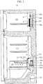
- FIG. 1 is a view illustrating a configuration of a refrigerator according to the embodiment of the present disclosure.
- the refrigerator 100 according to the embodiment of the present disclosure includes a lower refrigerating compartment 110 and an upper freezing compartment 120.
- the refrigerating compartment 110 contains a refrigerating compartment evaporator 106, a refrigerating compartment fan motor 106a, a refrigerating compartment fan 106b, and a refrigerating compartment heater 104a, which are arranged in an innermost cold air generating space thereof (the right region of FIG. 1 ).
- the refrigerating compartment heater 104a serves to prevent excessive temperature drop in the refrigerating compartment 110 via temperature compensation during dehumidification to control humidity. In a general mode, the refrigerating compartment heater 104a also serves to melt and remove frost formed at a surface of the refrigerating compartment evaporator 106.
- the refrigerating compartment evaporator 106 is located upstream of a blowing direction of the refrigerating compartment fan 106b, and the refrigerating compartment heater 104a is located downstream of the blowing direction.
- the refrigerating compartment heater 104a is located downstream of the blowing direction.
- the freezing compartment 120 contains a freezing compartment evaporator 108, a freezing compartment fan motor 108a, a freezing compartment fan 108b, and a freezing compartment heater 104b, which are arranged in an innermost cold air generating space thereof (the right region of FIG. 1 ).
- the freezing compartment heater 104b serves to melt and remove frost formed at a surface of the freezing compartment evaporator 108.
- Cold air generated from the freezing compartment evaporator 108 is blown into the freezing compartment 120 by rotation of the freezing compartment fan 108b.
- Expansion devices (capillary tubes, expansion valves, etc.) (not shown) to depressurize and expand a refrigerant are installed at an entrance of the refrigerating compartment evaporator 106 and an entrance of the freezing compartment evaporator 108.
- a condenser (not shown) is provided at an exit of a compressor 102.
- the refrigerating compartment evaporator 106, the expansion device for the refrigerating compartment evaporator 106, the freezing compartment evaporator 108, the expansion device for the freezing compartment evaporator 108, the condenser, and the compressor 102 are connected to one another via refrigerant pipes to constitute a single refrigerant cycle.
- the refrigerant cycle may further include, e.g., various shapes of valves and additional refrigerant pipes as necessary.
- the refrigerating compartment 110 contains a multi-purpose chamber 130 providing an independently partitioned storage space.
- the multi-purpose chamber 130 is separably coupled to a guide passage 134 to guide cold air into the multi-purpose chamber 130.
- a flap 133 is installed at an entrance of the guide passage 134.
- the flap 133 is hinged to the guide passage 134 and thus, an opening angle of the flap 133 is adjustable.
- the multi-purpose chamber 130 includes an inclined ceiling panel 132 made of an insulating material.
- the panel 132 is provided with a plurality of discharge holes, through which the cold air is supplied into the multi-purpose chamber 130.
- a damper 109 is installed above the refrigerating compartment fan 106b. If the damper 109 is opened, the cold air generated from the refrigerating compartment evaporator 106 is uniformly supplied into the entire refrigerating compartment 110. On the contrary, if the damper 109 is closed, the cold air generated from the refrigerating compartment evaporator 106 is supplied only into the multi-purpose chamber 130. The damper 109 is driven to be opened or closed by a damper motor 109a.
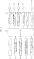
- FIG. 2 is a block diagram illustrating a control system of the refrigerator illustrated in FIG. 1 .
- a key input unit 204 a freezing compartment temperature sensor 206, a refrigerating compartment temperature sensor 208, a refrigerating compartment evaporator temperature sensor 222, and an outside air temperature sensor 224 are connected to an input side of a control unit 202.
- the key input unit 204 includes a plurality of function keys to set operating conditions of the refrigerator 100, such as a cooling mode (strong cooling or weak cooling) or a desired temperature.
- the freezing compartment temperature sensor 206 and the refrigerating compartment temperature sensor 208 respectively sense interior temperatures of the freezing compartment 120 and the refrigerating compartment 110 and transmit the sensed results to the control unit 202.
- the refrigerating compartment evaporator temperature sensor 222 senses a refrigerant evaporation temperature of the refrigerating compartment evaporator 106 and transmits the sensed result to the control unit 202.
- the outside air temperature sensor 224 senses the exterior temperature of the refrigerator 100, i.e. the temperature of outside air in a space where the refrigerator 100 is installed and transmits the sensed result to the control unit 202.
- a compressor drive unit 212, a freezing compartment fan drive unit 214, a refrigerating compartment fan drive unit 216, a damper drive unit 218, a display unit 210, and a defrosting heater drive unit 220 are connected to an output side of the control unit 202 to enable communication therebetween. These drive units respectively drive the compressor 102, the freezing compartment fan motor 108a, the refrigerating compartment fan motor 106a, the damper motor 109a, the refrigerating compartment heater 104a, and the freezing compartment heater 104b.
- the display unit 210 connected to the output side of the control unit 202 to enable communication therebetween, displays current operational states (temperature, etc.) or various preset values of the refrigerator.
- the control unit 202 controls general operation of the refrigerator 100 in cooperation with the above described various constituent elements, to allow the refrigerating compartment 110 and the freezing compartment 120 to reach preset temperatures.
- the control unit 202 enables automated dehumidification of the refrigerating compartment 110, to prevent formation of dewdrops or frost at the inner surface of the refrigerating compartment 110.
- dehumidification may be manually performed whenever a user requests (sets) dehumidification, regardless of the temperature of outside air.
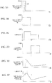
- FIGS. 3A-3F are views illustrating dehumidification characteristics of the refrigerator according to the embodiment.
- dehumidification involves an overlap section 302 in which heating the refrigerating compartment 110 for temperature compensation and cooling the refrigerating compartment 110 for dehumidification are performed simultaneously. This will be described in detail hereinafter.
- the refrigerating compartment heater 104a and the refrigerating compartment fan 106b of the refrigerating compartment 110 are operated together.
- the compressor 102 is operated to start cooling of the refrigerating compartment 110.
- the refrigerating compartment heater 104a and the refrigerating compartment fan 106b of the refrigerating compartment 110 are operated together, enabling simultaneous implementation of cooling and temperature compensation of the refrigerating compartment 110.
- 'overlap section' is a time section where a time section for cooling of the refrigerating compartment 110 and a time section for temperature compensation of the refrigerating compartment 110 overlap each other. If the refrigerating compartment heater 104a and the refrigerating compartment fan 106b of the refrigerating compartment 110 are operated together, cold air blown toward the refrigerating compartment 110 is dehumidified while passing through the surface of the refrigerating compartment evaporator 106 and immediately thereafter, is heated by the refrigerating compartment heater 104a for temperature compensation. In this way, the resulting dehumidified air is kept at a constant temperature. Thereafter, after cooling of the refrigerating compartment 110 is completed at time t2, the freezing compartment fan 108b is operated to start cooling of the freezing compartment 120. This cooling of the freezing compartment 120 may be omitted as necessary.
- the temperature of the refrigerating compartment 110 may be excessively lowered if the outside air has a low temperature. This cause more rapid temperature drop of the refrigerating compartment 110 in a section between the time t1 and the time t2 as compared to that illustrated in FIG. 3F and thus, the temperature of the refrigerating compartment 110 at time t3 may be much lower than that illustrated in FIG. 3F . This means that formation of ice or frost or freezing of food may occur in the refrigerating compartment 110.
- excessive temperature drop of the refrigerating compartment 110 may shorten a refrigerating compartment cooling time depending on the temperature of the refrigerating compartment 110, which may cause insufficient dehumidification (cooling) time of the refrigerating compartment 110, resulting in unsatisfactory dehumidification.
- temperature compensation may prevent excessive temperature drop of the refrigerating compartment 110, thereby preventing formation of ice or frost or freezing of food and achieving satisfactory dehumidification owing to sufficient dehumidification (cooling) time.
- FIG. 4 is a view illustrating a dehumidification control method of the refrigerator under the characteristics of FIG. 3 .
- the control unit 202 detects the temperature of outside air around the refrigerator 100 via the outside air sensor 224 (402). If the temperature of outside air corresponds to a low-temperature mode that is known as having a negative effect on normal cooling (i.e. operation to reach a preset temperature) of the refrigerator 100 (for example, if the temperature of outside air is 21°C or less) ('YES' in 404), dehumidification is performed (406 to 414). On the contrary, if the temperature of outside air does not correspond to the low-temperature mode, for example, if the temperature of outside air is more than 21 °C, general cooling is performed (416).
- the refrigerating compartment heater 104a is operated for temperature compensation of the refrigerating compartment 110.
- the refrigerating compartment fan 106b is operated until the compressor 102 begins operation, so as to supply heated air around the refrigerating compartment evaporator 106 into the refrigerating compartment 110 (406). This serves to reduce a temperature difference between cold air generated by new cooling and high-temperature air around the refrigerating compartment evaporator 106.
- the compressor 102 begins operation at time t1 to start cooling of the refrigerating compartment 110 (408).
- the overlap section 302 begins simultaneously with operation of the compressor 102.
- a preset time of the overlap section 302 passes after the compressor 102 begins operation, the refrigerating compartment fan 106b is continuously operated, but the refrigerating compartment heater 104a is turned off to end the overlap section 302 (410). If completion of dehumidification of the refrigerating compartment 110 is judged, the refrigerating compartment fan 106b is turned off to end dehumidification (412).
- a criterion to judge completion of dehumidification of the refrigerating compartment 110 may be previously set in the control unit 202 in consideration of cooling time of the refrigerating compartment 110, operation time of the refrigerating compartment heater 104a, the temperature of outside air, etc. Alternatively, dehumidification may be set to end when particular interior conditions of the refrigerating compartment 110 are satisfied. After completion of dehumidification, cooling of the freezing compartment 120 is selectively performed as necessary (414).
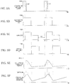
- FIGS. 5A-5F are views illustrating dehumidification characteristics of the refrigerator according to another embodiment of the present disclosure.
- dehumidification involves a section 502 in which the compressor 102 is turned off for a predetermined time after previous dehumidification (first dehumidification) (from t0 to t3) is completed and before following dehumidification (second dehumidification) (from t4 to t7) begins. This will be described in detail hereinafter.
- previous dehumidification ends at time t3 and following dehumidification begins at time t4.
- Both the previous dehumidification and the following dehumidification are performed similar to that illustrated in FIGS. 3A-3F .
- the refrigerating compartment heater 104a and the refrigerating compartment fan 106b of the refrigerating compartment 110 are operated together at time t4.
- the compressor 102 begins operation at time t5 to start cooling of the refrigerating compartment 110.
- the refrigerating compartment heater 104a and the refrigerating compartment fan 106b of the refrigerating compartment 100 are operated together, to enable simultaneous implementation of cooling and temperature compensation of the refrigerating compartment 110.
- 'overlap section' is a time section where a time section for cooling of the refrigerating compartment 110 and a time section for temperature compensation of the refrigerating compartment 110 overlap each other.
- the refrigerating compartment heater 104a and the refrigerating compartment fan 106b of the refrigerating compartment 110 are operated together, cold air blown toward the refrigerating compartment 110 is dehumidified while passing through the surface of the refrigerating compartment evaporator 106 and immediately thereafter, is heated by the refrigerating compartment heater 104a for temperature compensation. In this way, the resulting dehumidified air is kept at a constant temperature. Thereafter, after cooling of the refrigerating compartment 110 is completed at time t6, the freezing compartment fan 108b is operated to start cooling of the freezing compartment 120. This cooling of the freezing compartment 120 may be omitted as necessary.
- the compressor off section 502 is present between time t3 when previous dehumidification ends (i.e. compressor off time) and time t4 when following dehumidification begins (i.e. time when the refrigerating compartment 104a and the refrigerating compartment fan 106b are turned on). That is, the compressor off section 502 for a predetermined time t3 to t4 is present before the refrigerating compartment heater 104a and the refrigerating compartment fan 106b are turned on to perform following dehumidification.
- the compressor off section 502 serves to lengthen a low-humidity section obtained by previous dehumidification and to achieve pressure balance of a refrigerant cycle prior to beginning following dehumidification. That is, if following dehumidification (from t4 to t7) is begun excessively early in a state in which the humidity of the refrigerating compartment 110 is lowered by previous dehumidification (from t0 to t3), the following dehumidification is unnecessarily performed despite that the low-humidity section is continued by the previous dehumidification, resulting in unnecessary power consumption.
- the compressor off section 502 for a predetermined time after previous dehumidification and before following dehumidification prevents unnecessary power consumption due to hasty implementation of following dehumidification.
- the compressor off section 502 achieves pressure balance of a refrigerant cycle prior to performing following dehumidification, which ensures smooth operation of the compressor 102 when the compressor 102 begins operation for following dehumidification and also, prevents generation of shock due to pressure unbalance of a refrigerant cycle at the operation beginning time of the compressor 102, extending the lifespan of the compressor 102.
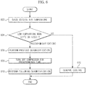
- FIG. 6 is a view illustrating a dehumidification control method of the refrigerator under the characteristics of FIGS. 5A-5F .
- the control unit 202 detects the temperature of outside air around the refrigerator 100 using the outside air temperature sensor 224 (602). If the temperature of outside air corresponds to a low-temperature mode that is known as having a negative effect on normal cooling (i.e. operation to reach a preset temperature) of the refrigerator 100 (for example, if the temperature of outside air is 21°C or less) ('YES' in 604), dehumidification is performed (606 to 610). On the contrary, if the temperature of outside air does not correspond to the low-temperature mode, for example, if the temperature of outside air is more than 21°C, general cooling is performed (612).
- dehumidification 606 to 610 involves previous dehumidification 606 and following dehumidification 610.
- the compressor off section (502 of FIG. 5C ) in which the compressor 102 is turned off for a predetermined time is set between the previous dehumidification 606 and the following dehumidification 610 (608).
- the previous dehumidification 606 and the following dehumidification 610 are performed as mentioned in the above description of FIGS. 5A-5F .
- the compressor off section (502 of FIG. 5C ) for a predetermined time after the previous dehumidification 606 and before the following dehumidification 610 prevents unnecessary power consumption due to hasty implementation of the following dehumidification 610.
- the compressor off section (502 of FIG. 5C ) achieves pressure balance of a refrigerant cycle prior to performing the following dehumidification 610, which ensures smooth operation of the compressor 102 when the compressor 102 begins operation for the following dehumidification 610 and also, prevents generation of shock due to pressure unbalance of a refrigerant cycle at the operation beginning time of the compressor 102, extending the lifespan of the compressor 102.
- FIG. 7 is a view illustrating a configuration of a refrigerator according to a further embodiment of the present disclosure.
- the refrigerator 700 according to the embodiment of the present disclosure includes a lower refrigerating compartment 710 and an upper freezing compartment 720.
- the refrigerating compartment 710 contains a refrigerating compartment evaporator 706, a refrigerating compartment fan motor 706a, a refrigerating compartment fan 706b, and a refrigerating compartment heater 704a, which are arranged in an innermost cold air generating space thereof (the right region of FIG. 7 ).
- the refrigerating compartment heater 704a serves to prevent excessive temperature drop in the refrigerating compartment 710 via temperature compensation during dehumidification to control humidity.
- the refrigerating compartment heater 704a also serves to melt and remove frost formed at a surface of the refrigerating compartment evaporator 706.
- the refrigerating compartment evaporator 706 is located upstream of a blowing direction of the refrigerating compartment fan 706b, and the refrigerating compartment heater 704a is located downstream of the blowing direction.
- the freezing compartment 720 contains a freezing compartment evaporator 708, a freezing compartment fan motor 708a, a freezing compartment fan 708b, and a freezing compartment heater 704b, which are arranged in an innermost cold air generating space thereof (the right region of FIG. 7 ).
- the freezing compartment heater 704b serves to melt and remove frost formed at a surface of the freezing compartment evaporator 708.
- Cold air generated from the freezing compartment evaporator 708 is blown into the freezing compartment 720 by rotation of the freezing compartment fan 708b.
- Expansion devices (capillary tubes, expansion valves, etc.) (not shown) to depressurize and expand a refrigerant are installed at an entrance of the refrigerating compartment evaporator 706 and an entrance of the freezing compartment evaporator 708.
- a condenser (not shown) is provided at an exit of a compressor 702.
- the refrigerating compartment evaporator 706, the expansion device for the refrigerating compartment evaporator 706, the freezing compartment evaporator 708, the expansion device for the freezing compartment evaporator 708, the condenser, and the compressor 702 are connected to one another via refrigerant pipes to constitute a single refrigerant cycle.
- the refrigerant cycle may further include, e.g., various shapes of valves and additional refrigerant pipes as necessary.
- the refrigerating compartment 710 contains a multi-purpose chamber 730 providing an independently partitioned storage space.
- the multi-purpose chamber 730 is separably coupled to a guide passage 734 to guide cold air into the multi-purpose chamber 730.
- a flap 733 is installed at an entrance of the guide passage 734.
- the flap 733 is hinged to the guide passage 734 and thus, an opening angle of the flap 733 is adjustable.
- the multi-purpose chamber 730 includes an inclined ceiling panel 732 made of an insulating material.
- the panel 732 is provided with a plurality of discharge holes, through which the cold air is supplied into the multi-purpose chamber 730.
- a damper 709 is installed above the refrigerating compartment fan 706b. If the damper 709 is opened, the cold air generated from the refrigerating compartment evaporator 706 is uniformly supplied into the entire refrigerating compartment 710. On the contrary, if the damper 709 is closed, the cold air generated from the refrigerating compartment evaporator 706 is supplied only into the multi-purpose chamber 730. The damper 709 is driven to be opened or closed by a damper motor 709a.
- the refrigerating compartment heater 704a is located upstream of a blowing direction of the refrigerating compartment fan 706b and the refrigerating compartment evaporator 706 is located downstream of the blowing direction. That is, although the refrigerator 100 illustrated in FIG. 1 has the arrangement order of the refrigerating compartment fan 106b - the refrigerating compartment evaporator 106 - the refrigerating compartment heater 104a, the refrigerator 700 illustrated in FIG. 7 has the arrangement order of the refrigerating compartment fan 706b - the refrigerating compartment heater 704a - the refrigerating compartment evaporator 706.
- the arrangement order of the refrigerating compartment fan 706b - the refrigerating compartment heater 704a - the refrigerating compartment evaporator 706 of FIG. 7 has been frequently used in refrigerators and therefore, may be advantageous because it achieves dehumidification effects according to the embodiments even using conventional configurations.
- one or more embodiments include a dehumidification control method of a refrigerator to effectively perform both temperature compensation and dehumidification of a refrigerating compartment so as to prevent formation of dewdrops in the refrigerating compartment.
Applications Claiming Priority (1)
| Application Number | Priority Date | Filing Date | Title |
|---|---|---|---|
| KR1020100105694A KR101837452B1 (ko) | 2010-10-28 | 2010-10-28 | 냉장고 및 그 제습 운전 제어 방법 |
Publications (3)
| Publication Number | Publication Date |
|---|---|
| EP2447634A2 EP2447634A2 (en) | 2012-05-02 |
| EP2447634A3 EP2447634A3 (en) | 2017-08-16 |
| EP2447634B1 true EP2447634B1 (en) | 2020-12-16 |
Family
ID=44936189
Family Applications (1)
| Application Number | Title | Priority Date | Filing Date |
|---|---|---|---|
| EP11186279.3A Active EP2447634B1 (en) | 2010-10-28 | 2011-10-24 | Refrigerator and dehumidification control method thereof |
Country Status (4)
| Country | Link |
|---|---|
| US (1) | US9719714B2 (ko) |
| EP (1) | EP2447634B1 (ko) |
| KR (1) | KR101837452B1 (ko) |
| CN (1) | CN102538378B (ko) |
Families Citing this family (19)
| Publication number | Priority date | Publication date | Assignee | Title |
|---|---|---|---|---|
| US9004369B2 (en) * | 2010-03-24 | 2015-04-14 | Whirlpool Corporation | Systems and methods for multi-sense control algorithm for atomizers in refrigerators |
| JP5847626B2 (ja) * | 2012-03-26 | 2016-01-27 | ハイアールアジア株式会社 | 冷蔵庫及びその運転方法 |
| US20150338135A1 (en) * | 2012-11-22 | 2015-11-26 | Daikin Industries, Ltd. | Refrigeration device for container |
| CN104344678B (zh) * | 2013-07-31 | 2018-05-08 | 博西华电器(江苏)有限公司 | 制冷器具及其除湿方法 |
| CN105526770B (zh) * | 2014-09-29 | 2020-04-24 | 青岛海尔智能技术研发有限公司 | 冰箱内多功能间室的控制方法及冰箱 |
| CN104315799B (zh) * | 2014-11-10 | 2016-10-05 | 合肥美的电冰箱有限公司 | 温度补偿组件和冰箱 |
| CN104457098B (zh) * | 2014-12-10 | 2017-01-18 | 广东格兰仕集团有限公司 | 冰箱变温室及其除湿控制方法 |
| CN106352647B (zh) * | 2016-08-30 | 2019-02-12 | 合肥美的电冰箱有限公司 | 温度控制方法及温度控制装置和冰箱 |
| DE102016220163A1 (de) * | 2016-10-14 | 2018-04-19 | BSH Hausgeräte GmbH | Kältegerät mit Dörrfunktion und Betriebsverfahren dafür |
| CN106969594A (zh) * | 2017-05-03 | 2017-07-21 | 合肥美的电冰箱有限公司 | 保鲜控制方法、制冷系统和冰箱 |
| WO2019193648A1 (ja) * | 2018-04-03 | 2019-10-10 | 三菱電機株式会社 | 冷蔵庫 |
| CN110440519B (zh) * | 2018-05-04 | 2022-11-04 | 青岛海尔智能技术研发有限公司 | 一种冰箱的控制方法、装置、存储介质和冰箱 |
| JP7059116B2 (ja) * | 2018-06-19 | 2022-04-25 | フクシマガリレイ株式会社 | 冷却貯蔵庫 |
| CN108917257B (zh) * | 2018-06-30 | 2020-11-13 | 端黎明 | 一种多功能冷冻冷藏装置 |
| KR102631643B1 (ko) * | 2018-12-21 | 2024-02-01 | 삼성전자주식회사 | 와인 셀러 및 이의 제어 방법 |
| CN112923628B (zh) * | 2019-12-06 | 2022-10-28 | 青岛海尔电冰箱有限公司 | 一种具有干区间室的冰箱 |
| CN112923630A (zh) * | 2019-12-06 | 2021-06-08 | 青岛海尔电冰箱有限公司 | 一种具有干区间室的冰箱 |
| CN111536753B (zh) * | 2020-05-08 | 2021-09-21 | 青岛海尔电冰箱有限公司 | 冰箱及其控制方法 |
| CN115111874A (zh) * | 2022-06-07 | 2022-09-27 | 珠海格力电器股份有限公司 | 一种冰箱干储控制方法、装置及冰箱 |
Family Cites Families (23)
| Publication number | Priority date | Publication date | Assignee | Title |
|---|---|---|---|---|
| US2689110A (en) * | 1949-10-19 | 1954-09-14 | Gen Motors Corp | Household refrigerator with humidity control |
| US2717499A (en) * | 1952-12-10 | 1955-09-13 | Servel Inc | Ice maker |
| JPH06300421A (ja) | 1993-04-14 | 1994-10-28 | Matsushita Refrig Co Ltd | 冷凍冷蔵庫の扉装置 |
| KR960005749U (ko) * | 1994-07-29 | 1996-02-17 | 공기조화기의 이슬맺힘 방지장치 | |
| JP3334660B2 (ja) * | 1998-05-19 | 2002-10-15 | 三菱電機株式会社 | 冷凍サイクルの制御装置およびその制御方法 |
| JP4229555B2 (ja) | 1999-12-17 | 2009-02-25 | 福島工業株式会社 | 温度調節機能付き保管庫 |
| CN1160541C (zh) | 2000-11-23 | 2004-08-04 | 广东科龙电器股份有限公司 | 电冰箱自动温度补偿方法及使用该方法的电冰箱 |
| US6931870B2 (en) * | 2002-12-04 | 2005-08-23 | Samsung Electronics Co., Ltd. | Time division multi-cycle type cooling apparatus and method for controlling the same |
| JP3642335B2 (ja) * | 2003-05-30 | 2005-04-27 | ダイキン工業株式会社 | 冷凍装置 |
| CN1297793C (zh) | 2004-02-16 | 2007-01-31 | 海信(北京)电器有限公司 | 自动速冻冰箱及其控制方法 |
| US20060255164A1 (en) * | 2005-05-13 | 2006-11-16 | W.C. Wood Company Limited | Remote sensing system for a dehumidifier |
| KR100687931B1 (ko) * | 2005-08-11 | 2007-02-27 | 삼성전자주식회사 | 냉장고의 운전제어방법 |
| KR101266867B1 (ko) * | 2006-05-16 | 2013-05-23 | 삼성전자주식회사 | 냉장고 및 그 제어 방법 |
| BRPI0810497A2 (pt) * | 2007-04-26 | 2015-07-21 | Panasonic Corp | Refrigerador e dispositivo elétrico |
| EP2199714B9 (en) * | 2007-10-09 | 2019-12-18 | Panasonic Corporation | Refrigerator |
| DE202008000757U1 (de) * | 2007-12-28 | 2009-04-30 | Liebherr-Hausgeräte Ochsenhausen GmbH | Kühl- und/oder Gefriergerät |
| WO2010039800A2 (en) * | 2008-09-30 | 2010-04-08 | Thermo Fisher Scientific (Asheville) Llc | Frost reduction by active circulation |
| JP2010104964A (ja) * | 2008-10-31 | 2010-05-13 | Smc Corp | 冷凍式エアドライヤ |
| DE102008054934A1 (de) * | 2008-12-18 | 2010-07-01 | BSH Bosch und Siemens Hausgeräte GmbH | Kältegerät sowie Verfahren zur Temperaturregelung in einem Kältegerät |
| KR20100072944A (ko) * | 2008-12-22 | 2010-07-01 | 삼성전자주식회사 | 냉장고 및 그 제어방법 |
| JP5362537B2 (ja) * | 2008-12-25 | 2013-12-11 | 三洋電機株式会社 | 空調制御装置、冷却システム及び空調制御プログラム |
| JP5570191B2 (ja) | 2009-11-30 | 2014-08-13 | パナソニックヘルスケア株式会社 | インキュベータ |
| US20120079840A1 (en) * | 2010-09-30 | 2012-04-05 | Lukasse Leijn Johannes Sjerp | Method and system for temperature control in refrigerated storage spaces |
-
2010
- 2010-10-28 KR KR1020100105694A patent/KR101837452B1/ko active IP Right Grant
-
2011
- 2011-10-24 EP EP11186279.3A patent/EP2447634B1/en active Active
- 2011-10-26 US US13/317,690 patent/US9719714B2/en active Active
- 2011-10-28 CN CN201110340048.3A patent/CN102538378B/zh not_active Expired - Fee Related
Non-Patent Citations (1)
| Title |
|---|
| None * |
Also Published As
| Publication number | Publication date |
|---|---|
| CN102538378A (zh) | 2012-07-04 |
| KR20120044428A (ko) | 2012-05-08 |
| US9719714B2 (en) | 2017-08-01 |
| US20120102984A1 (en) | 2012-05-03 |
| KR101837452B1 (ko) | 2018-03-12 |
| EP2447634A3 (en) | 2017-08-16 |
| CN102538378B (zh) | 2016-02-10 |
| EP2447634A2 (en) | 2012-05-02 |
Similar Documents
| Publication | Publication Date | Title |
|---|---|---|
| EP2447634B1 (en) | Refrigerator and dehumidification control method thereof | |
| US6931870B2 (en) | Time division multi-cycle type cooling apparatus and method for controlling the same | |
| KR100453236B1 (ko) | 다용도실을 구비한 냉장고 및 그 제어방법 | |
| EP2217872B1 (en) | Control method of refrigerator | |
| KR100800591B1 (ko) | 냉장고의 제어 방법 | |
| US20080178621A1 (en) | Refrigerator and operation control method thereof | |
| US20060117768A1 (en) | Defrost apparatus of refrigerator | |
| KR20130037354A (ko) | 냉장고 및 그 제어방법 | |
| US20130192280A1 (en) | Refrigerator and defrosting method thereof | |
| KR20060110687A (ko) | 냉장고의 제어 방법 | |
| JPH1144474A (ja) | 冷蔵庫及びその制御方法 | |
| US20100139300A1 (en) | Refrigeration and control method thereof | |
| KR101668302B1 (ko) | 냉장고 | |
| KR101655802B1 (ko) | 냉장고 및 그 동작방법 | |
| KR102010382B1 (ko) | 냉장고 및 그 운전 방법 | |
| JPH11311473A (ja) | 冷蔵庫の制御方法 | |
| JP5363247B2 (ja) | 冷蔵庫 | |
| KR20130028841A (ko) | 냉장고 | |
| KR101266867B1 (ko) | 냉장고 및 그 제어 방법 | |
| KR102641371B1 (ko) | 냉장고 | |
| JP2003106739A (ja) | 冷蔵庫 | |
| JPH11304332A (ja) | 冷蔵庫の制御方法 | |
| JP2002206840A (ja) | 冷蔵庫 | |
| KR101508773B1 (ko) | 독립 냉각 냉장고 | |
| KR101959309B1 (ko) | 냉장고 및 그 운전 방법 |
Legal Events
| Date | Code | Title | Description |
|---|---|---|---|
| PUAI | Public reference made under article 153(3) epc to a published international application that has entered the european phase |
Free format text: ORIGINAL CODE: 0009012 |
|
| AK | Designated contracting states |
Kind code of ref document: A2 Designated state(s): AL AT BE BG CH CY CZ DE DK EE ES FI FR GB GR HR HU IE IS IT LI LT LU LV MC MK MT NL NO PL PT RO RS SE SI SK SM TR |
|
| AX | Request for extension of the european patent |
Extension state: BA ME |
|
| RAP1 | Party data changed (applicant data changed or rights of an application transferred) |
Owner name: SAMSUNG ELECTRONICS CO., LTD. |
|
| PUAL | Search report despatched |
Free format text: ORIGINAL CODE: 0009013 |
|
| AK | Designated contracting states |
Kind code of ref document: A3 Designated state(s): AL AT BE BG CH CY CZ DE DK EE ES FI FR GB GR HR HU IE IS IT LI LT LU LV MC MK MT NL NO PL PT RO RS SE SI SK SM TR |
|
| AX | Request for extension of the european patent |
Extension state: BA ME |
|
| RIC1 | Information provided on ipc code assigned before grant |
Ipc: F25D 17/04 20060101AFI20170711BHEP Ipc: F25D 17/06 20060101ALI20170711BHEP |
|
| STAA | Information on the status of an ep patent application or granted ep patent |
Free format text: STATUS: REQUEST FOR EXAMINATION WAS MADE |
|
| 17P | Request for examination filed |
Effective date: 20171123 |
|
| RBV | Designated contracting states (corrected) |
Designated state(s): AL AT BE BG CH CY CZ DE DK EE ES FI FR GB GR HR HU IE IS IT LI LT LU LV MC MK MT NL NO PL PT RO RS SE SI SK SM TR |
|
| STAA | Information on the status of an ep patent application or granted ep patent |
Free format text: STATUS: EXAMINATION IS IN PROGRESS |
|
| 17Q | First examination report despatched |
Effective date: 20191204 |
|
| GRAP | Despatch of communication of intention to grant a patent |
Free format text: ORIGINAL CODE: EPIDOSNIGR1 |
|
| STAA | Information on the status of an ep patent application or granted ep patent |
Free format text: STATUS: GRANT OF PATENT IS INTENDED |
|
| INTG | Intention to grant announced |
Effective date: 20200723 |
|
| GRAS | Grant fee paid |
Free format text: ORIGINAL CODE: EPIDOSNIGR3 |
|
| GRAA | (expected) grant |
Free format text: ORIGINAL CODE: 0009210 |
|
| STAA | Information on the status of an ep patent application or granted ep patent |
Free format text: STATUS: THE PATENT HAS BEEN GRANTED |
|
| AK | Designated contracting states |
Kind code of ref document: B1 Designated state(s): AL AT BE BG CH CY CZ DE DK EE ES FI FR GB GR HR HU IE IS IT LI LT LU LV MC MK MT NL NO PL PT RO RS SE SI SK SM TR |
|
| REG | Reference to a national code |
Ref country code: GB Ref legal event code: FG4D |
|
| REG | Reference to a national code |
Ref country code: DE Ref legal event code: R096 Ref document number: 602011069644 Country of ref document: DE |
|
| REG | Reference to a national code |
Ref country code: IE Ref legal event code: FG4D |
|
| REG | Reference to a national code |
Ref country code: AT Ref legal event code: REF Ref document number: 1345961 Country of ref document: AT Kind code of ref document: T Effective date: 20210115 |
|
| PG25 | Lapsed in a contracting state [announced via postgrant information from national office to epo] |
Ref country code: FI Free format text: LAPSE BECAUSE OF FAILURE TO SUBMIT A TRANSLATION OF THE DESCRIPTION OR TO PAY THE FEE WITHIN THE PRESCRIBED TIME-LIMIT Effective date: 20201216 Ref country code: RS Free format text: LAPSE BECAUSE OF FAILURE TO SUBMIT A TRANSLATION OF THE DESCRIPTION OR TO PAY THE FEE WITHIN THE PRESCRIBED TIME-LIMIT Effective date: 20201216 Ref country code: NO Free format text: LAPSE BECAUSE OF FAILURE TO SUBMIT A TRANSLATION OF THE DESCRIPTION OR TO PAY THE FEE WITHIN THE PRESCRIBED TIME-LIMIT Effective date: 20210316 Ref country code: GR Free format text: LAPSE BECAUSE OF FAILURE TO SUBMIT A TRANSLATION OF THE DESCRIPTION OR TO PAY THE FEE WITHIN THE PRESCRIBED TIME-LIMIT Effective date: 20210317 |
|
| REG | Reference to a national code |
Ref country code: AT Ref legal event code: MK05 Ref document number: 1345961 Country of ref document: AT Kind code of ref document: T Effective date: 20201216 |
|
| REG | Reference to a national code |
Ref country code: NL Ref legal event code: MP Effective date: 20201216 |
|
| PG25 | Lapsed in a contracting state [announced via postgrant information from national office to epo] |
Ref country code: LV Free format text: LAPSE BECAUSE OF FAILURE TO SUBMIT A TRANSLATION OF THE DESCRIPTION OR TO PAY THE FEE WITHIN THE PRESCRIBED TIME-LIMIT Effective date: 20201216 Ref country code: SE Free format text: LAPSE BECAUSE OF FAILURE TO SUBMIT A TRANSLATION OF THE DESCRIPTION OR TO PAY THE FEE WITHIN THE PRESCRIBED TIME-LIMIT Effective date: 20201216 Ref country code: BG Free format text: LAPSE BECAUSE OF FAILURE TO SUBMIT A TRANSLATION OF THE DESCRIPTION OR TO PAY THE FEE WITHIN THE PRESCRIBED TIME-LIMIT Effective date: 20210316 |
|
| PG25 | Lapsed in a contracting state [announced via postgrant information from national office to epo] |
Ref country code: HR Free format text: LAPSE BECAUSE OF FAILURE TO SUBMIT A TRANSLATION OF THE DESCRIPTION OR TO PAY THE FEE WITHIN THE PRESCRIBED TIME-LIMIT Effective date: 20201216 Ref country code: NL Free format text: LAPSE BECAUSE OF FAILURE TO SUBMIT A TRANSLATION OF THE DESCRIPTION OR TO PAY THE FEE WITHIN THE PRESCRIBED TIME-LIMIT Effective date: 20201216 |
|
| REG | Reference to a national code |
Ref country code: LT Ref legal event code: MG9D |
|
| PG25 | Lapsed in a contracting state [announced via postgrant information from national office to epo] |
Ref country code: SM Free format text: LAPSE BECAUSE OF FAILURE TO SUBMIT A TRANSLATION OF THE DESCRIPTION OR TO PAY THE FEE WITHIN THE PRESCRIBED TIME-LIMIT Effective date: 20201216 Ref country code: CZ Free format text: LAPSE BECAUSE OF FAILURE TO SUBMIT A TRANSLATION OF THE DESCRIPTION OR TO PAY THE FEE WITHIN THE PRESCRIBED TIME-LIMIT Effective date: 20201216 Ref country code: EE Free format text: LAPSE BECAUSE OF FAILURE TO SUBMIT A TRANSLATION OF THE DESCRIPTION OR TO PAY THE FEE WITHIN THE PRESCRIBED TIME-LIMIT Effective date: 20201216 Ref country code: LT Free format text: LAPSE BECAUSE OF FAILURE TO SUBMIT A TRANSLATION OF THE DESCRIPTION OR TO PAY THE FEE WITHIN THE PRESCRIBED TIME-LIMIT Effective date: 20201216 Ref country code: PT Free format text: LAPSE BECAUSE OF FAILURE TO SUBMIT A TRANSLATION OF THE DESCRIPTION OR TO PAY THE FEE WITHIN THE PRESCRIBED TIME-LIMIT Effective date: 20210416 Ref country code: SK Free format text: LAPSE BECAUSE OF FAILURE TO SUBMIT A TRANSLATION OF THE DESCRIPTION OR TO PAY THE FEE WITHIN THE PRESCRIBED TIME-LIMIT Effective date: 20201216 Ref country code: RO Free format text: LAPSE BECAUSE OF FAILURE TO SUBMIT A TRANSLATION OF THE DESCRIPTION OR TO PAY THE FEE WITHIN THE PRESCRIBED TIME-LIMIT Effective date: 20201216 |
|
| PG25 | Lapsed in a contracting state [announced via postgrant information from national office to epo] |
Ref country code: PL Free format text: LAPSE BECAUSE OF FAILURE TO SUBMIT A TRANSLATION OF THE DESCRIPTION OR TO PAY THE FEE WITHIN THE PRESCRIBED TIME-LIMIT Effective date: 20201216 Ref country code: AT Free format text: LAPSE BECAUSE OF FAILURE TO SUBMIT A TRANSLATION OF THE DESCRIPTION OR TO PAY THE FEE WITHIN THE PRESCRIBED TIME-LIMIT Effective date: 20201216 |
|
| REG | Reference to a national code |
Ref country code: DE Ref legal event code: R097 Ref document number: 602011069644 Country of ref document: DE |
|
| PG25 | Lapsed in a contracting state [announced via postgrant information from national office to epo] |
Ref country code: IS Free format text: LAPSE BECAUSE OF FAILURE TO SUBMIT A TRANSLATION OF THE DESCRIPTION OR TO PAY THE FEE WITHIN THE PRESCRIBED TIME-LIMIT Effective date: 20210416 |
|
| PLBE | No opposition filed within time limit |
Free format text: ORIGINAL CODE: 0009261 |
|
| STAA | Information on the status of an ep patent application or granted ep patent |
Free format text: STATUS: NO OPPOSITION FILED WITHIN TIME LIMIT |
|
| PG25 | Lapsed in a contracting state [announced via postgrant information from national office to epo] |
Ref country code: AL Free format text: LAPSE BECAUSE OF FAILURE TO SUBMIT A TRANSLATION OF THE DESCRIPTION OR TO PAY THE FEE WITHIN THE PRESCRIBED TIME-LIMIT Effective date: 20201216 Ref country code: IT Free format text: LAPSE BECAUSE OF FAILURE TO SUBMIT A TRANSLATION OF THE DESCRIPTION OR TO PAY THE FEE WITHIN THE PRESCRIBED TIME-LIMIT Effective date: 20201216 |
|
| 26N | No opposition filed |
Effective date: 20210917 |
|
| PG25 | Lapsed in a contracting state [announced via postgrant information from national office to epo] |
Ref country code: ES Free format text: LAPSE BECAUSE OF FAILURE TO SUBMIT A TRANSLATION OF THE DESCRIPTION OR TO PAY THE FEE WITHIN THE PRESCRIBED TIME-LIMIT Effective date: 20201216 Ref country code: DK Free format text: LAPSE BECAUSE OF FAILURE TO SUBMIT A TRANSLATION OF THE DESCRIPTION OR TO PAY THE FEE WITHIN THE PRESCRIBED TIME-LIMIT Effective date: 20201216 |
|
| PG25 | Lapsed in a contracting state [announced via postgrant information from national office to epo] |
Ref country code: SI Free format text: LAPSE BECAUSE OF FAILURE TO SUBMIT A TRANSLATION OF THE DESCRIPTION OR TO PAY THE FEE WITHIN THE PRESCRIBED TIME-LIMIT Effective date: 20201216 |
|
| REG | Reference to a national code |
Ref country code: CH Ref legal event code: PL |
|
| PG25 | Lapsed in a contracting state [announced via postgrant information from national office to epo] |
Ref country code: IS Free format text: LAPSE BECAUSE OF FAILURE TO SUBMIT A TRANSLATION OF THE DESCRIPTION OR TO PAY THE FEE WITHIN THE PRESCRIBED TIME-LIMIT Effective date: 20210416 |
|
| REG | Reference to a national code |
Ref country code: BE Ref legal event code: MM Effective date: 20211031 |
|
| PG25 | Lapsed in a contracting state [announced via postgrant information from national office to epo] |
Ref country code: MC Free format text: LAPSE BECAUSE OF FAILURE TO SUBMIT A TRANSLATION OF THE DESCRIPTION OR TO PAY THE FEE WITHIN THE PRESCRIBED TIME-LIMIT Effective date: 20201216 |
|
| PG25 | Lapsed in a contracting state [announced via postgrant information from national office to epo] |
Ref country code: LU Free format text: LAPSE BECAUSE OF NON-PAYMENT OF DUE FEES Effective date: 20211024 Ref country code: BE Free format text: LAPSE BECAUSE OF NON-PAYMENT OF DUE FEES Effective date: 20211031 |
|
| PG25 | Lapsed in a contracting state [announced via postgrant information from national office to epo] |
Ref country code: LI Free format text: LAPSE BECAUSE OF NON-PAYMENT OF DUE FEES Effective date: 20211031 Ref country code: CH Free format text: LAPSE BECAUSE OF NON-PAYMENT OF DUE FEES Effective date: 20211031 |
|
| PG25 | Lapsed in a contracting state [announced via postgrant information from national office to epo] |
Ref country code: FR Free format text: LAPSE BECAUSE OF NON-PAYMENT OF DUE FEES Effective date: 20211031 |
|
| PG25 | Lapsed in a contracting state [announced via postgrant information from national office to epo] |
Ref country code: IE Free format text: LAPSE BECAUSE OF NON-PAYMENT OF DUE FEES Effective date: 20211024 |
|
| PGFP | Annual fee paid to national office [announced via postgrant information from national office to epo] |
Ref country code: GB Payment date: 20220920 Year of fee payment: 12 |
|
| PGFP | Annual fee paid to national office [announced via postgrant information from national office to epo] |
Ref country code: DE Payment date: 20220621 Year of fee payment: 12 |
|
| PG25 | Lapsed in a contracting state [announced via postgrant information from national office to epo] |
Ref country code: HU Free format text: LAPSE BECAUSE OF FAILURE TO SUBMIT A TRANSLATION OF THE DESCRIPTION OR TO PAY THE FEE WITHIN THE PRESCRIBED TIME-LIMIT; INVALID AB INITIO Effective date: 20111024 Ref country code: CY Free format text: LAPSE BECAUSE OF FAILURE TO SUBMIT A TRANSLATION OF THE DESCRIPTION OR TO PAY THE FEE WITHIN THE PRESCRIBED TIME-LIMIT Effective date: 20201216 |