EP2445381B1 - Kochvorrichtung - Google Patents
Kochvorrichtung Download PDFInfo
- Publication number
- EP2445381B1 EP2445381B1 EP10740264.6A EP10740264A EP2445381B1 EP 2445381 B1 EP2445381 B1 EP 2445381B1 EP 10740264 A EP10740264 A EP 10740264A EP 2445381 B1 EP2445381 B1 EP 2445381B1
- Authority
- EP
- European Patent Office
- Prior art keywords
- cooking
- peripheral wall
- food support
- fastening means
- cooking device
- Prior art date
- Legal status (The legal status is an assumption and is not a legal conclusion. Google has not performed a legal analysis and makes no representation as to the accuracy of the status listed.)
- Not-in-force
Links
Images


Classifications
-
- A—HUMAN NECESSITIES
- A47—FURNITURE; DOMESTIC ARTICLES OR APPLIANCES; COFFEE MILLS; SPICE MILLS; SUCTION CLEANERS IN GENERAL
- A47J—KITCHEN EQUIPMENT; COFFEE MILLS; SPICE MILLS; APPARATUS FOR MAKING BEVERAGES
- A47J37/00—Baking; Roasting; Grilling; Frying
- A47J37/06—Roasters; Grills; Sandwich grills
- A47J37/07—Roasting devices for outdoor use; Barbecues
- A47J37/0704—Roasting devices for outdoor use; Barbecues with horizontal fire box
-
- A—HUMAN NECESSITIES
- A47—FURNITURE; DOMESTIC ARTICLES OR APPLIANCES; COFFEE MILLS; SPICE MILLS; SUCTION CLEANERS IN GENERAL
- A47J—KITCHEN EQUIPMENT; COFFEE MILLS; SPICE MILLS; APPARATUS FOR MAKING BEVERAGES
- A47J37/00—Baking; Roasting; Grilling; Frying
- A47J37/04—Roasting apparatus with movably-mounted food supports or with movable heating implements; Spits
-
- A—HUMAN NECESSITIES
- A47—FURNITURE; DOMESTIC ARTICLES OR APPLIANCES; COFFEE MILLS; SPICE MILLS; SUCTION CLEANERS IN GENERAL
- A47J—KITCHEN EQUIPMENT; COFFEE MILLS; SPICE MILLS; APPARATUS FOR MAKING BEVERAGES
- A47J37/00—Baking; Roasting; Grilling; Frying
- A47J37/06—Roasters; Grills; Sandwich grills
- A47J37/07—Roasting devices for outdoor use; Barbecues
- A47J37/0704—Roasting devices for outdoor use; Barbecues with horizontal fire box
- A47J37/0709—Roasting devices for outdoor use; Barbecues with horizontal fire box with electric heating elements
-
- A—HUMAN NECESSITIES
- A47—FURNITURE; DOMESTIC ARTICLES OR APPLIANCES; COFFEE MILLS; SPICE MILLS; SUCTION CLEANERS IN GENERAL
- A47J—KITCHEN EQUIPMENT; COFFEE MILLS; SPICE MILLS; APPARATUS FOR MAKING BEVERAGES
- A47J37/00—Baking; Roasting; Grilling; Frying
- A47J37/06—Roasters; Grills; Sandwich grills
- A47J37/07—Roasting devices for outdoor use; Barbecues
- A47J37/0704—Roasting devices for outdoor use; Barbecues with horizontal fire box
- A47J37/0713—Roasting devices for outdoor use; Barbecues with horizontal fire box with gas burners
-
- A—HUMAN NECESSITIES
- A47—FURNITURE; DOMESTIC ARTICLES OR APPLIANCES; COFFEE MILLS; SPICE MILLS; SUCTION CLEANERS IN GENERAL
- A47J—KITCHEN EQUIPMENT; COFFEE MILLS; SPICE MILLS; APPARATUS FOR MAKING BEVERAGES
- A47J37/00—Baking; Roasting; Grilling; Frying
- A47J37/06—Roasters; Grills; Sandwich grills
- A47J37/07—Roasting devices for outdoor use; Barbecues
- A47J37/0786—Accessories
- A47J2037/0795—Adjustable food supports, e.g. for height adjustment
Definitions
- the present invention relates to cooking devices and more particularly those which are intended to be used outdoors, such as for example barbecues.
- the principle behind these cooking devices is to provide sufficient heat for the food to cook.
- the cooking medium is a grid or a plancha.
- the food carrier is placed above the heat source in a cooking position.
- the cooking position is predetermined by the fixing means.
- the fixing means usually consist of protuberances provided on the inside of the rigid lateral envelope and on which the food support rests.
- Barbecue-type cooking devices in that they comprise a heat source, constitute relatively dangerous devices, on the one hand for operators who must approach it to intervene on the device itself or on the device. food being cooked, and secondly for children who may be tempted to touch hot parts of the device.
- the problem proposed by the present invention is to provide a cooking device providing better safety of use, in particular during cleaning or refueling operations.
- cleaning or refueling operations can be performed without displacing or degrading the food during cooking, which simultaneously prevents the flow of cooking residues outside the device.
- the lateral offset of the movable lower portion of the interchangeable subassembly allows access to the receiving means of food residues, without having to move the food support and the food that it can support.
- the peripheral wall also encircles the fastening means over most of the longitudinal dimension of the fastening means.
- the peripheral wall comprises four sectors, two of these adjacent sectors being fixed and forming the rigid connecting means, and the two other sectors being each articulated to one of the fixed sectors to take a closed position peripheral wall and a peripheral wall opening position.
- the four sectors are of the same shape.
- standardization of the constituent parts of the device, in particular the parts constituting the peripheral wall which may be made of cast iron, and the size of the constituent elements and therefore the cost of producing these elements are reduced.
- the base comprises a base, occupying the end cross section of the tubular structure defined by the peripheral wall, and fixed by means of rigid connection.
- the lower closure of the tubular structure defined by the peripheral wall further allows it to be used as a support, for example for a gas cylinder or for cooking utensils.
- the base is separated from the peripheral wall by a ventilation gap. This gap is not very visible, but nevertheless very effective to ensure good ventilation of the heat source.
- the movable lower part may be pivotally mounted along a lateral articulation of longitudinal axis and integral with the fixed upper part.
- the invention is compatible with the production of a cooking device that can have different types of heat source.
- the fixed upper part comprises the fixing means which supports the food support, and comprises a heat source of the gas burner or electrical resistance type
- the movable lower part comprises a basin forming a reflector and receptacle. recovery of cooking residues.
- the food carrier may be a grill, a plancha or a wok.
- the fixed upper part comprises the fixing means which supports the food support
- the movable lower part comprises a coal-fired or other solid-fuel type heat source and an ash recovery receptacle and cooking residues.
- the fixing means may advantageously comprise manual actuation means able to move the food support continuously between a proximal cooking position in which the intermediate space is reduced and a distal cooking position in which the intermediate space is increased, the manual actuating means having a gripping portion which is accessible by the user away from the fastening means.
- the food carrier is preferably in the form of a grid.
- the fixing means comprises a continuous peripheral crown covering the upper edge of the tubular peripheral wall, and opposite which the food support is deported in the direction of the base.
- This design of the manual actuation means is simple and allows an easy and optimal movement of the food support, without the risk of touching the food support still hot.
- the cooking device further comprises mechanical ignition ventilation means.
- the mechanical ignition ventilation means comprise a turbine adapted to propel air on the charcoal hearth or other solid fuels.
- the cooking device comprises, in the lower part of the interior space delimited by the rigid lateral envelope, a housing adapted to receive a gas cylinder.
- the cooking device illustrated on the figure 1 , comprises a rigid connection means consisting of a rigid lateral envelope 100, and a base 1 adapted to rest on a use surface 2.
- the use surface 2 may be the earth in a garden, or a terrace, for example.
- a food support 3 is provided for receiving and supporting food to be cooked.
- the food support 3 is designed to be positioned in an intermediate cooking position P by a fixing means 4, in a cooking space 200 defined by the rigid lateral envelope 100.
- the food positioned on the food support 3 is cooked by the heat emitted by a heat source 5 provided below the food support 3 and at a distance therefrom by defining an intermediate space 6.
- the rigid lateral envelope 100 defines an outer wall 10b, away from an inner wall 10a to define between them a heat-insulating space 8.
- the heat is spread with difficulty in the air of the heat-insulating space 8 and disperses before reaching the outer wall 10b.
- the intermediate cooking position P is situated between a proximal cooking position P1 and a distal cooking position P2.
- the food support 3 is a substantially circular grid in the embodiment illustrated in FIG. figure 1 .
- the food support may be a grid square, rectangular or any other form.
- the food support 3 is a plancha.
- the rigid side shell 100 is made of cast iron. This has the advantage that the cast iron does not rust. Thus, the cooking device has a good behavior over time, and withstands bad weather.
- the thermal insulation space 8 is closed at its upper part by a ring 25.
- This ring 25 is attached to the rigid lateral envelope 100.
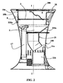
- the figure 2 illustrates in more detail a second embodiment in which the heat source 5 is a coal or other solid fuel hearth.
- Mechanical ignition ventilation 17 is provided to supply the heat source 5 with combustion air.
- the mechanical ignition ventilation 17 may include a turbine capable of propelling air on the coal or other solid fuel fires, the turbine being driven by an electric motor powered by a battery or photovoltaic cells.
- the advantage of photovoltaic cells is that they can be flexible and thus be easily integrated into the external shape of the cooking device.
- the inner wall 10a comprises an upper section S10a ( figures 1 and 2 ) substantially cylindrical connecting to a lower section I10a ( figures 1 and 2 ) substantially conical.
- the substantially cylindrical upper section S10a facilitates the design of the means for supporting and moving the food support 3.
- the lower section I10a facilitates the automatic adaptation of the heat source 5 according to the amount of food to be cooked.
- the amount of food to be cooked when the amount of food to be cooked is low, it can be placed in the center of the food support 3, and a reduced amount of coal or other solid fuels is used which naturally concentrates in the center of the conical portion, which has the effect of also concentrating heat in the center of the food support 3. Thus reduces the consumption of coal or other solid fuels.
- the heat source 5 is a gas burner, in the form of diametrical burner bars arranged in a star, below the food support 3.
- the rigid lateral envelope 100 is a continuous tubular structure which encircles the internal space 101 between the base 1a and the fastening means 4 about a longitudinal axis I-I.
- the cross section of the peripheral wall 100, in a plane perpendicular to the longitudinal axis I-I, is substantially circular.
- the peripheral wall 100 comprises a lower section 102 generally conical and narrowing away from the base 1a.
- the upper section 103 is generally inverted conical, narrowing towards the base 1a.
- the lower section occupies about a quarter of the longitudinal dimension of the device along the axis I-I, the upper portion 103 occupying three quarters of this longitudinal dimension.
- the base 1a is formed of a base which occupies the end cross-section of the tubular structure defined by the peripheral wall 100. As illustrated in the figures, the base 1a may comprise retractable wheels 30, for example wheels which it is possible to exit or retract by actuating a lever accessible from the interior space 101.
- the fixing means 4 and the heat source 5 form an interchangeable cooking sub-assembly 45, illustrated in isolation on the figure 12 , and reported in an outer peripheral structure 300 as illustrated on the Figures 4 to 9 .
- the outer peripheral structure 300 comprises the base-shaped base 1a, the tubular peripheral wall 100 with two inverted conical sections 102 and 103, and a continuous upper ring 25 which covers the upper edge of the tubular peripheral wall 100.
- the peripheral wall 100 comprises a fixed part forming a rigid connection means 1 which connects the base 1a to the upper ring 25.
- the fixed part forming the rigid connection means 1 is formed, in the illustrated embodiment, of two fixed sectors wall 100a and 100b.
- each of the fixed sectors 100a and 100b is articulated a mobile sector, respectively 100c and 100d.
- the movable sectors 100c and 100d are pivotally movable between a closed position illustrated in FIGS. Figures 4 to 6 and an open position illustrated on the Figures 7 to 9 . In the open position, access to the interior space 101 is released.
- the articulation of the moving sectors 100c and 100d is effected by means of hinges, such as the hinges 101c and 101d, along a pivot axis parallel to the longitudinal axis I-I.
- the four sectors 100a, 100b, 100c, 100d are of the same shape, that is to say that they have the same general shape, while being provided with specific fastening and assembly means, for example hinges, locating tabs, screw holes as shown in the figures. They can be made by molding using the same mold, for example cast iron.
- the base of the tubular peripheral wall 100 may be slightly spaced from the base 1a, by defining a ventilation gap 400, for example illustrated in FIGS. figures 5 , 6 and 8 .
- This cooking subassembly comprises a peripheral ring constituting the fixing means 4, intended to be fixed by means of rigid connection 1 formed by the fixed sectors 100a and 100b ( Figures 4 to 9 ) of the peripheral wall 100, and which can support a food support 3 such as the grid illustrated on the figure 10 .
- the interchangeable cooking subassembly 45 in the embodiment of the figure 12 , comprises the heat source 5, in the form of a star-shaped burner bar burner gas burner.
- the fastening means 4 in the form of a cylinder section can be fixed to the rigid connection means 1 by radial tabs such as the tab 4a, which engage and fix themselves by screws on corresponding shoulders such as the shoulder 40a. visible on figures 4 , 7 and 9 .
- the small cross section of the tabs 4a effectively opposes the heat transfer from the fixing means 4 to the peripheral wall 100.
- the interchangeable cooking subassembly 45 comprises a lower basin 21, intended to retain the cooking residues such as grease flowing from the food during cooking.
- This basin 21 is visible on the figure 10 but it was not illustrated on the figure 12 .
- This lower basin 21 is movable relative to the fixing device 4 by pivoting along a lateral articulation integral with the fixed upper part constituted by the fixing means 4, and having an axis of rotation parallel to the longitudinal axis I-I.
- the interchangeable cooking subassembly 45 comprises a fixed upper part constituted by the fixing means 4 and the heat source 5, and comprises a movable lower part constituted by the lower basin 21, which part lower movable which can take a retracted position in which it is in longitudinal alignment with the food support 3, and an extended position in which, after opening of the peripheral wall 100, it is laterally offset to facilitate access.
- a variant of this embodiment of figures 10 and 11 is to replace the gas burner with an electrical resistance.
- the basin 21 may be made of reflective metal, so that it is on the one hand a reflector for reflecting towards the food support 3 the infrared radiation emanating from the burner or the electrical resistance, and on the other hand a receptacle allowing the recovery of cooking residues.
- the food carrier 3, represented by a grid may also be a plancha or a wok.
- FIGS 13 to 18 illustrate a heat source embodiment of the coal fire or other solid fuel type.
- the modification in this embodiment essentially resides in the structure of the interchangeable cooking subassembly 45.
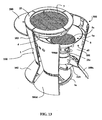
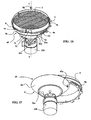
- the interchangeable cooking subassembly 45 is illustrated in isolation on the figures 17 and 18 and it comprises the fixing means 4, in the general form of a cylinder section that can be fixed in the external peripheral structure 300, and a coal-type heat source 5, better visible on the figure 13 .
- the heat source 5, in this embodiment, is movably mounted by longitudinal lateral axis rotation vis-à-vis the fixing device 4: the figures 17 and 18 illustrate the arrangement of the axis of rotation 45a, placed in the vicinity of the periphery of the fastening means 4, oriented in a longitudinal direction parallel to the longitudinal axis II, and arranged so that the possible lateral offset of the heat source 5 is made in the opening made by the movable sectors 100c and 100d of the peripheral wall 100.
- the heat source comprises a frustoconical focus 5a flared towards the food support 3, whose bottom is obscured by a grid 5c allowing the ashes which are recovered with the cooking residues to pass into a conical shaped lower receptacle 21a which empties into a removable tank 21 b.
- the removable tank 21b further comprises adjustable flaps 21c air inlet, for adjusting the combustion in the home.
- the fastening means 4 in the form of a cylinder section form an inner wall (10a on the Figures 1 to 3 ), spaced from the upper portion of the peripheral wall 100 to which it is connected by thermal bridges of small cross section (the tabs 4a of the figure 12 ).
- the heat released by the heat source 5 is not easily transmitted to the peripheral wall 100, which therefore remains relatively cold.
- the device according to the invention may advantageously have a height of 85 to 95 cm so as to rest on the ground and to constitute a relatively high worktop, inaccessible to children.
- the continuous peripheral ring 25 which covers the upper edge of the tubular peripheral wall 100, forms a hollow seal which obscures the upper edge of the peripheral wall 100, and which allows the opening of the movable sectors 100c and 100d without adversely affecting the aesthetics of the device.
- the fixing means 4 comprises manual actuating means 7 able to move continuously, along the longitudinal axis II, the food support 3 between a proximal cooking position P1 and a distal cooking position P2 ( figure 1 ).
- the manual actuating means 7 comprise a gripping portion 70 such as a radial pull, which is accessible by the user away from the fastening means 4 and therefore away from the hot parts of the device.
- the gripping portion 70 is integral with a rotary cylinder 71 mounted to slide and rotate around the cylinder section forming the fastening means 4.
- the rotary cylinder 71 comprises ramps 72, for example three ramps distributed at the periphery. .
- the rotary cylinder 71 is held axially in position by fixed lugs 73 engaged in slots 74 of the rotary cylinder.
- An outer peripheral arch 75 carries centripetal radial lugs 76, which bear on the ramps 72 and pass through oblong vertical slots 77 of the fixing means 4, the inner ends of the lugs 76 coming to support the food support 3.
- the rotary cylinder 71 can be rotated around the longitudinal axis I-I and thus longitudinally move the food support 3.
- the figure 3 illustrates an embodiment in which the heat source 5 is a gas burner.
- a difference from embodiments with a coal or other solid fuel fireplace is the presence of a housing 18 for accommodating a gas cylinder.
- Residue recovery means 21 are provided as in the previous embodiment, and are placed under the gas burner 5, to prevent cooking grease from falling on the gas cylinder.
- the food carrier 3 may be a grill, a plancha, or a wok.
- a removable or retractable bell 120 as illustrated in FIG. figure 19 , able to cover the cooking device to protect the food, to avoid hot grease splashes on the user, and to promote cooking. It is also possible to add a radial shelf 500, attached to the rigid connection means 1.
Claims (12)
- Garmachungsvorrichtung, umfassend:- einen Gargutträger (3) zum Aufnehmen und Abstützen der zu garenden Nahrungsmittel,- eine Fixiereinheit (4) zum Aufnehmen und Stützen des Gargutträgers (3),- eine Basis (1a) zur Abstützung auf einer Einsatzfläche (2),- ein starres Verbindungsmittel (1), das die Fixiereinheit (4) und die Basis (1a) in fester Stellung und bezüglich einer Längsachse (I-I) mit Abstand voneinander halten,- eine Wärmequelle (5), die zwischen dem Gargutträger (3) und die Basis (1a) angeordnet ist und dabei zu dem Gargutträger (3) einen Zwischenraum (6) abgrenzt,- einen Innenraum (101) zwischen der Fixiereinheit (4) und der Basis (1a), wobei in dem Innenraum (101):- die Fixiereinheit (4) und die Wärmequelle (5) eine austauschbare Garmachungs-Teileinheit (45) bilden, die in das starre Verbindungsmittel (1) eingesetzt ist,- eine rohrförmige, durchgehende Umfangswand (100) den Innenraum (101) zwischen der Basis (1a) und der Fixiereinheit (4) um die Längsachse (I-I) umschließt,- die Umfangswand (100) einen festen Teil hat, der das starre Verbindungsmittel (1) bildet, an dem wenigstens ein bewegliches Teilstück (100c, 100d) angelenkt ist, das zwischen einer Schließstellung und einer geöffneten Stellung der Umfangswand beweglich ist, um den Zugang in den Innenraum (101) freizugeben,- die austauschbare Garmachungs-Teileinheit (45) einen oberen, festen Teil (4) und einen unteren, beweglichen Teil (21) aufweist, wobei der untere, bewegliche Teil eine eingefahrene Stellung, in der er mit dem Gargutträger (3) in Längsrichtung fluchtet, und eine ausgefahrene Stellung einnehmen kann, in der er nach Öffnung der Umfangswand (100) seitlich versetzt ist, um den Zugang zu erleichtern,dadurch gekennzeichnet, dass die Fixiereinheit (4) einen am Umfang umlaufenden Ring (25) aufweist, der den oberen Rand der Umfangswand (100) überdeckt, und dass der Gargutträger (3) relativ zu dem Ring in Richtung auf die Basis verschoben ist.
- Garmachungsvorrichtung nach Anspruch 1, dadurch gekennzeichnet, dass die Umfangswand (100) auch die Fixiereinheit (4) auf dem größten Teil der Längserstreckung der Fixiereinheit (4) umschließt.
- Garmachungsvorrichtung nach einem der Ansprüche 1 oder 2, dadurch gekennzeichnet, dass die Umfangswand aus vier Sektoren besteht, von denen zwei aneinander angrenzende Sektoren (100a, 100b) fest sind und das starre Verbindungsmittel (1) bilden, während von den beiden anderen Sektoren (100c, 100d) jeder an einem der festen Sektoren (100a, 100b) angelenkt ist, um eine geschlossene Stellung und eine geöffnete Stellung der Umfangswand zu ermöglichen.
- Garmachungsvorrichtung nach Anspruch 3, dadurch gekennzeichnet, dass die vier Sektoren (100a, 100b, 100c, 100d) gleiche Form haben.
- Garmachungsvorrichtung nach einem der Ansprüche 1 bis 4, dadurch gekennzeichnet, dass die Basis (1a) einen Sockel hat, der den Endquerschnitt der durch die Umfangswand (100) gebildeten, rohrförmigen Struktur einnimmt und an dem starren Verbindungsmittel (1) befestigt ist.
- Garmachungsvorrichtung nach Anspruch 5, dadurch gekennzeichnet, dass der Sockel (1a) von der Umfangswand (100) durch eine Belüftungslücke (400) getrennt ist.
- Garmachungsvorrichtung nach einem der Ansprüche 1 bis 6, dadurch gekennzeichnet, dass der untere, bewegliche Teil (21) um eine in Längsrichtung verlaufende, seitliche Achse (45a), die an dem oberen, festen Teil (4) angebracht ist, schwenkbar gelagert ist.
- Garmachungsvorrichtung nach einem der Ansprüche 1 bis 7, dadurch gekennzeichnet, dass der obere, feste Teil das Fixierorgan (4), das den Gargutträger (3) stützt, sowie eine Wärmequelle (5) in Form eines Gasbrenners oder eines elektrischen Widerstands umfasst, wobei der untere, bewegliche Teil eine Wanne (21) hat, die einen Reflektor sowie einen Behälter für die Aufnahme der Garmachungsrückstände bildet.
- Garmachungsvorrichtung nach Anspruch 8, dadurch gekennzeichnet, dass der Gargutträger (3) ein Grillrost, ein Plancha-Grill oder ein Wok ist.
- Garmachungsvorrichtung nach einem der Ansprüche 1 bis 7, dadurch gekennzeichnet, dass der obere, feste Teil das Fixierorgan (4) für die Abstützung des Gargutträgers (3) aufweist und der untere, bewegliche Teil eine Wärmequelle (5) in Form eines Kohlebrennraums oder eines Brennraums für andere feste Brennstoffe sowie einen Behälter (21) zur Aufnahme der Asche und der Garmachungsrückstände umfasst.
- Garmachungsvorrichtung nach Anspruch 10, dadurch gekennzeichnet, dass das Fixierorgan (4) Mittel (7) zur manuellen Betätigung für die kontinuierliche Verstellung des Gargutträgers (3) zwischen einer proximalen Garmachungsstellung (P1), in der der Zwischenraum (6) reduziert ist, und einer distalen Garmachungsstellung (P2) mit vergrößertem Zwischenraum (6) verstellt ist, wobei die manuellen Betätigungsmittel (7) ein Greiforgan (70) aufweisen, das für die Bedienungsperson mit Abstand von dem Fixierorgan (4) zugänglich ist.
- Garmachungsvorrichtung nach einem der Ansprüche 10 oder 11, dadurch gekennzeichnet, dass der Gargutträger (3) ein Grillrost ist.
Applications Claiming Priority (2)
| Application Number | Priority Date | Filing Date | Title |
|---|---|---|---|
| FR0954362A FR2947163A1 (fr) | 2009-06-25 | 2009-06-25 | Dispositif de cuisson |
| PCT/IB2010/001580 WO2010150095A1 (fr) | 2009-06-25 | 2010-06-25 | Dispositif de cuisson |
Publications (2)
| Publication Number | Publication Date |
|---|---|
| EP2445381A1 EP2445381A1 (de) | 2012-05-02 |
| EP2445381B1 true EP2445381B1 (de) | 2013-08-14 |
Family
ID=41440637
Family Applications (1)
| Application Number | Title | Priority Date | Filing Date |
|---|---|---|---|
| EP10740264.6A Not-in-force EP2445381B1 (de) | 2009-06-25 | 2010-06-25 | Kochvorrichtung |
Country Status (3)
| Country | Link |
|---|---|
| EP (1) | EP2445381B1 (de) |
| FR (1) | FR2947163A1 (de) |
| WO (1) | WO2010150095A1 (de) |
Cited By (3)
| Publication number | Priority date | Publication date | Assignee | Title |
|---|---|---|---|---|
| FR3084826A1 (fr) | 2018-08-10 | 2020-02-14 | Marc Ledermann | Dispositif de cuisson a structure ouvrante |
| FR3084825A1 (fr) | 2018-08-10 | 2020-02-14 | Marc Ledermann | Dispositif de cuisson a chaleur soufflee et brassee |
| EP3852587B1 (de) * | 2018-08-10 | 2022-11-09 | Marc Ledermann | Kochgerät mit geblasener und gerührter wärme |
Families Citing this family (2)
| Publication number | Priority date | Publication date | Assignee | Title |
|---|---|---|---|---|
| FR2974994A1 (fr) * | 2011-05-11 | 2012-11-16 | Cookout | Dispositif de cuisson a gaz |
| DE202013006604U1 (de) * | 2013-07-20 | 2013-08-20 | Steffen Mau | Ofen |
Family Cites Families (11)
| Publication number | Priority date | Publication date | Assignee | Title |
|---|---|---|---|---|
| US3667448A (en) * | 1971-01-28 | 1972-06-06 | Jack Dorian | Portable brazier with cleaning means |
| US3933145A (en) * | 1974-08-05 | 1976-01-20 | Harry Reich | Recirculating barbeque device |
| CH688303A5 (it) * | 1993-07-30 | 1997-07-31 | Sala Mauro | Forno barbecue per la cottura di alimenti. |
| GB2290220A (en) * | 1994-06-10 | 1995-12-20 | Kwei Tang Chang | Electric barbecue grill |
| US5458053A (en) * | 1994-06-27 | 1995-10-17 | Hsiao; Yung-Fang | Barbecue grill |
| US6065466A (en) * | 1996-08-14 | 2000-05-23 | Masagril, Llc | Barbecue and patio table combination |
| US5809988A (en) * | 1997-03-24 | 1998-09-22 | Wagner; Larry C. | Adjustable cooking grill |
| KR100365593B1 (ko) * | 1999-12-31 | 2002-12-26 | 주식회사에이테크엔지니어링 | 숯불조리기 |
| DE20111703U1 (de) * | 2001-07-18 | 2001-11-22 | Polzer Gmbh F | Gasverbrennendes Gerät, insbesondere Bräter, Grill oder Kocher |
| DE20216178U1 (de) * | 2002-10-21 | 2004-02-26 | 3Rd Angle (U.K.) Ltd., Highley | Grillgerät |
| ITPN20040022A1 (it) * | 2004-03-24 | 2004-06-24 | Smartech Italia S R L Ora Smar | "apparecchiatura mobile provvista di superficie per la cottura a contatto" |
-
2009
- 2009-06-25 FR FR0954362A patent/FR2947163A1/fr active Pending
-
2010
- 2010-06-25 EP EP10740264.6A patent/EP2445381B1/de not_active Not-in-force
- 2010-06-25 WO PCT/IB2010/001580 patent/WO2010150095A1/fr active Application Filing
Cited By (3)
| Publication number | Priority date | Publication date | Assignee | Title |
|---|---|---|---|---|
| FR3084826A1 (fr) | 2018-08-10 | 2020-02-14 | Marc Ledermann | Dispositif de cuisson a structure ouvrante |
| FR3084825A1 (fr) | 2018-08-10 | 2020-02-14 | Marc Ledermann | Dispositif de cuisson a chaleur soufflee et brassee |
| EP3852587B1 (de) * | 2018-08-10 | 2022-11-09 | Marc Ledermann | Kochgerät mit geblasener und gerührter wärme |
Also Published As
| Publication number | Publication date |
|---|---|
| EP2445381A1 (de) | 2012-05-02 |
| WO2010150095A1 (fr) | 2010-12-29 |
| FR2947163A1 (fr) | 2010-12-31 |
Similar Documents
| Publication | Publication Date | Title |
|---|---|---|
| EP2445381B1 (de) | Kochvorrichtung | |
| FR2739542A1 (fr) | Appareil de cuisson exterieure a fonctions multiples | |
| EP2648582A1 (de) | Grill- oder bratrostartige kochvorrichtung | |
| EP2512308B1 (de) | Gasgriller | |
| EP1441629B1 (de) | Bratrost mit vertikaler mulde, der mit holzkohle, lavagestein, holz, gas und anderen brennstoffen verwendet wird | |
| CA2803494A1 (fr) | Barbecue compact | |
| EP1445541A2 (de) | Feuerstelle für mehrere Funktionen | |
| EP0719987B1 (de) | Verbesserter Gaskocher | |
| EP3852587B1 (de) | Kochgerät mit geblasener und gerührter wärme | |
| EP1772084A2 (de) | Kochmulde | |
| FR2711053A1 (fr) | Barbecue à gaz à cuisson réglable. | |
| FR2803994A1 (fr) | Caisson mobile pour le maintien en temperature et le rechauffage des plats cuisines | |
| FR2755503A1 (fr) | Four multifonctions | |
| FR2812529A1 (fr) | Gril au charbon de bois | |
| WO2020030805A1 (fr) | Dispositif de cuisson à structure ouvrante | |
| EP0017522A1 (de) | Kinetischer Kamin, der als Bratvorrichtung benutzt werden kann | |
| EP3852588A1 (de) | Kochvorrichtung mit mehreren trägern und/oder mehreren utensilien | |
| CH665469A5 (fr) | Fourneau transportable. | |
| FR2665050A1 (fr) | Dispositif de chauffage de l'air ambiant autour de cultures quelconques. | |
| WO2018162849A1 (fr) | Dispositif de cuisson nomade, de type barbecue ou plancha | |
| FR3114735A1 (fr) | Dispositif de cuisson d’aliments | |
| FR3104001A1 (fr) | Dispositif de gestion de la chaleur pour appareil à fumer de type pipe à eau | |
| FR2873911A1 (fr) | Appareil de cuisson de type barbecue | |
| FR3080527A1 (fr) | Barbecue a foyers verticaux et enceinte de cuisson a parois | |
| FR2757608A1 (fr) | Four multifonctions |
Legal Events
| Date | Code | Title | Description |
|---|---|---|---|
| PUAI | Public reference made under article 153(3) epc to a published international application that has entered the european phase |
Free format text: ORIGINAL CODE: 0009012 |
|
| 17P | Request for examination filed |
Effective date: 20120125 |
|
| AK | Designated contracting states |
Kind code of ref document: A1 Designated state(s): AL AT BE BG CH CY CZ DE DK EE ES FI FR GB GR HR HU IE IS IT LI LT LU LV MC MK MT NL NO PL PT RO SE SI SK SM TR |
|
| DAX | Request for extension of the european patent (deleted) | ||
| GRAP | Despatch of communication of intention to grant a patent |
Free format text: ORIGINAL CODE: EPIDOSNIGR1 |
|
| GRAS | Grant fee paid |
Free format text: ORIGINAL CODE: EPIDOSNIGR3 |
|
| GRAP | Despatch of communication of intention to grant a patent |
Free format text: ORIGINAL CODE: EPIDOSNIGR1 |
|
| INTG | Intention to grant announced |
Effective date: 20130605 |
|
| GRAA | (expected) grant |
Free format text: ORIGINAL CODE: 0009210 |
|
| AK | Designated contracting states |
Kind code of ref document: B1 Designated state(s): AL AT BE BG CH CY CZ DE DK EE ES FI FR GB GR HR HU IE IS IT LI LT LU LV MC MK MT NL NO PL PT RO SE SI SK SM TR |
|
| REG | Reference to a national code |
Ref country code: GB Ref legal event code: FG4D Free format text: NOT ENGLISH |
|
| REG | Reference to a national code |
Ref country code: CH Ref legal event code: EP Ref country code: AT Ref legal event code: REF Ref document number: 626274 Country of ref document: AT Kind code of ref document: T Effective date: 20130815 |
|
| REG | Reference to a national code |
Ref country code: IE Ref legal event code: FG4D Free format text: LANGUAGE OF EP DOCUMENT: FRENCH |
|
| REG | Reference to a national code |
Ref country code: DE Ref legal event code: R096 Ref document number: 602010009471 Country of ref document: DE Effective date: 20131010 |
|
| REG | Reference to a national code |
Ref country code: NL Ref legal event code: VDEP Effective date: 20130814 Ref country code: AT Ref legal event code: MK05 Ref document number: 626274 Country of ref document: AT Kind code of ref document: T Effective date: 20130814 |
|
| REG | Reference to a national code |
Ref country code: LT Ref legal event code: MG4D |
|
| PG25 | Lapsed in a contracting state [announced via postgrant information from national office to epo] |
Ref country code: LT Free format text: LAPSE BECAUSE OF FAILURE TO SUBMIT A TRANSLATION OF THE DESCRIPTION OR TO PAY THE FEE WITHIN THE PRESCRIBED TIME-LIMIT Effective date: 20130814 Ref country code: NO Free format text: LAPSE BECAUSE OF FAILURE TO SUBMIT A TRANSLATION OF THE DESCRIPTION OR TO PAY THE FEE WITHIN THE PRESCRIBED TIME-LIMIT Effective date: 20131114 Ref country code: IS Free format text: LAPSE BECAUSE OF FAILURE TO SUBMIT A TRANSLATION OF THE DESCRIPTION OR TO PAY THE FEE WITHIN THE PRESCRIBED TIME-LIMIT Effective date: 20131214 Ref country code: CY Free format text: LAPSE BECAUSE OF FAILURE TO SUBMIT A TRANSLATION OF THE DESCRIPTION OR TO PAY THE FEE WITHIN THE PRESCRIBED TIME-LIMIT Effective date: 20130821 Ref country code: SE Free format text: LAPSE BECAUSE OF FAILURE TO SUBMIT A TRANSLATION OF THE DESCRIPTION OR TO PAY THE FEE WITHIN THE PRESCRIBED TIME-LIMIT Effective date: 20130814 Ref country code: AT Free format text: LAPSE BECAUSE OF FAILURE TO SUBMIT A TRANSLATION OF THE DESCRIPTION OR TO PAY THE FEE WITHIN THE PRESCRIBED TIME-LIMIT Effective date: 20130814 Ref country code: PT Free format text: LAPSE BECAUSE OF FAILURE TO SUBMIT A TRANSLATION OF THE DESCRIPTION OR TO PAY THE FEE WITHIN THE PRESCRIBED TIME-LIMIT Effective date: 20131216 Ref country code: HR Free format text: LAPSE BECAUSE OF FAILURE TO SUBMIT A TRANSLATION OF THE DESCRIPTION OR TO PAY THE FEE WITHIN THE PRESCRIBED TIME-LIMIT Effective date: 20130814 |
|
| PG25 | Lapsed in a contracting state [announced via postgrant information from national office to epo] |
Ref country code: GR Free format text: LAPSE BECAUSE OF FAILURE TO SUBMIT A TRANSLATION OF THE DESCRIPTION OR TO PAY THE FEE WITHIN THE PRESCRIBED TIME-LIMIT Effective date: 20131115 Ref country code: PL Free format text: LAPSE BECAUSE OF FAILURE TO SUBMIT A TRANSLATION OF THE DESCRIPTION OR TO PAY THE FEE WITHIN THE PRESCRIBED TIME-LIMIT Effective date: 20130814 Ref country code: LV Free format text: LAPSE BECAUSE OF FAILURE TO SUBMIT A TRANSLATION OF THE DESCRIPTION OR TO PAY THE FEE WITHIN THE PRESCRIBED TIME-LIMIT Effective date: 20130814 Ref country code: FI Free format text: LAPSE BECAUSE OF FAILURE TO SUBMIT A TRANSLATION OF THE DESCRIPTION OR TO PAY THE FEE WITHIN THE PRESCRIBED TIME-LIMIT Effective date: 20130814 Ref country code: SI Free format text: LAPSE BECAUSE OF FAILURE TO SUBMIT A TRANSLATION OF THE DESCRIPTION OR TO PAY THE FEE WITHIN THE PRESCRIBED TIME-LIMIT Effective date: 20130814 |
|
| PG25 | Lapsed in a contracting state [announced via postgrant information from national office to epo] |
Ref country code: CY Free format text: LAPSE BECAUSE OF FAILURE TO SUBMIT A TRANSLATION OF THE DESCRIPTION OR TO PAY THE FEE WITHIN THE PRESCRIBED TIME-LIMIT Effective date: 20130814 |
|
| PG25 | Lapsed in a contracting state [announced via postgrant information from national office to epo] |
Ref country code: CZ Free format text: LAPSE BECAUSE OF FAILURE TO SUBMIT A TRANSLATION OF THE DESCRIPTION OR TO PAY THE FEE WITHIN THE PRESCRIBED TIME-LIMIT Effective date: 20130814 Ref country code: NL Free format text: LAPSE BECAUSE OF FAILURE TO SUBMIT A TRANSLATION OF THE DESCRIPTION OR TO PAY THE FEE WITHIN THE PRESCRIBED TIME-LIMIT Effective date: 20130814 Ref country code: EE Free format text: LAPSE BECAUSE OF FAILURE TO SUBMIT A TRANSLATION OF THE DESCRIPTION OR TO PAY THE FEE WITHIN THE PRESCRIBED TIME-LIMIT Effective date: 20130814 Ref country code: RO Free format text: LAPSE BECAUSE OF FAILURE TO SUBMIT A TRANSLATION OF THE DESCRIPTION OR TO PAY THE FEE WITHIN THE PRESCRIBED TIME-LIMIT Effective date: 20130814 Ref country code: SK Free format text: LAPSE BECAUSE OF FAILURE TO SUBMIT A TRANSLATION OF THE DESCRIPTION OR TO PAY THE FEE WITHIN THE PRESCRIBED TIME-LIMIT Effective date: 20130814 Ref country code: DK Free format text: LAPSE BECAUSE OF FAILURE TO SUBMIT A TRANSLATION OF THE DESCRIPTION OR TO PAY THE FEE WITHIN THE PRESCRIBED TIME-LIMIT Effective date: 20130814 |
|
| PG25 | Lapsed in a contracting state [announced via postgrant information from national office to epo] |
Ref country code: IT Free format text: LAPSE BECAUSE OF FAILURE TO SUBMIT A TRANSLATION OF THE DESCRIPTION OR TO PAY THE FEE WITHIN THE PRESCRIBED TIME-LIMIT Effective date: 20130814 Ref country code: ES Free format text: LAPSE BECAUSE OF FAILURE TO SUBMIT A TRANSLATION OF THE DESCRIPTION OR TO PAY THE FEE WITHIN THE PRESCRIBED TIME-LIMIT Effective date: 20130814 |
|
| PLBE | No opposition filed within time limit |
Free format text: ORIGINAL CODE: 0009261 |
|
| STAA | Information on the status of an ep patent application or granted ep patent |
Free format text: STATUS: NO OPPOSITION FILED WITHIN TIME LIMIT |
|
| 26N | No opposition filed |
Effective date: 20140515 |
|
| REG | Reference to a national code |
Ref country code: DE Ref legal event code: R097 Ref document number: 602010009471 Country of ref document: DE Effective date: 20140515 |
|
| REG | Reference to a national code |
Ref country code: DE Ref legal event code: R119 Ref document number: 602010009471 Country of ref document: DE |
|
| PG25 | Lapsed in a contracting state [announced via postgrant information from national office to epo] |
Ref country code: MC Free format text: LAPSE BECAUSE OF FAILURE TO SUBMIT A TRANSLATION OF THE DESCRIPTION OR TO PAY THE FEE WITHIN THE PRESCRIBED TIME-LIMIT Effective date: 20130814 Ref country code: LU Free format text: LAPSE BECAUSE OF FAILURE TO SUBMIT A TRANSLATION OF THE DESCRIPTION OR TO PAY THE FEE WITHIN THE PRESCRIBED TIME-LIMIT Effective date: 20140625 |
|
| REG | Reference to a national code |
Ref country code: CH Ref legal event code: PL |
|
| GBPC | Gb: european patent ceased through non-payment of renewal fee |
Effective date: 20140625 |
|
| REG | Reference to a national code |
Ref country code: IE Ref legal event code: MM4A |
|
| REG | Reference to a national code |
Ref country code: DE Ref legal event code: R119 Ref document number: 602010009471 Country of ref document: DE Effective date: 20150101 |
|
| REG | Reference to a national code |
Ref country code: FR Ref legal event code: ST Effective date: 20150227 |
|
| PG25 | Lapsed in a contracting state [announced via postgrant information from national office to epo] |
Ref country code: CH Free format text: LAPSE BECAUSE OF NON-PAYMENT OF DUE FEES Effective date: 20140630 Ref country code: DE Free format text: LAPSE BECAUSE OF NON-PAYMENT OF DUE FEES Effective date: 20150101 Ref country code: IE Free format text: LAPSE BECAUSE OF NON-PAYMENT OF DUE FEES Effective date: 20140625 Ref country code: LI Free format text: LAPSE BECAUSE OF NON-PAYMENT OF DUE FEES Effective date: 20140630 |
|
| PG25 | Lapsed in a contracting state [announced via postgrant information from national office to epo] |
Ref country code: FR Free format text: LAPSE BECAUSE OF NON-PAYMENT OF DUE FEES Effective date: 20140630 Ref country code: GB Free format text: LAPSE BECAUSE OF NON-PAYMENT OF DUE FEES Effective date: 20140625 |
|
| PG25 | Lapsed in a contracting state [announced via postgrant information from national office to epo] |
Ref country code: MT Free format text: LAPSE BECAUSE OF FAILURE TO SUBMIT A TRANSLATION OF THE DESCRIPTION OR TO PAY THE FEE WITHIN THE PRESCRIBED TIME-LIMIT Effective date: 20130814 |
|
| PG25 | Lapsed in a contracting state [announced via postgrant information from national office to epo] |
Ref country code: SM Free format text: LAPSE BECAUSE OF FAILURE TO SUBMIT A TRANSLATION OF THE DESCRIPTION OR TO PAY THE FEE WITHIN THE PRESCRIBED TIME-LIMIT Effective date: 20130814 |
|
| PG25 | Lapsed in a contracting state [announced via postgrant information from national office to epo] |
Ref country code: BG Free format text: LAPSE BECAUSE OF FAILURE TO SUBMIT A TRANSLATION OF THE DESCRIPTION OR TO PAY THE FEE WITHIN THE PRESCRIBED TIME-LIMIT Effective date: 20130814 |
|
| PG25 | Lapsed in a contracting state [announced via postgrant information from national office to epo] |
Ref country code: TR Free format text: LAPSE BECAUSE OF FAILURE TO SUBMIT A TRANSLATION OF THE DESCRIPTION OR TO PAY THE FEE WITHIN THE PRESCRIBED TIME-LIMIT Effective date: 20130814 Ref country code: HU Free format text: LAPSE BECAUSE OF FAILURE TO SUBMIT A TRANSLATION OF THE DESCRIPTION OR TO PAY THE FEE WITHIN THE PRESCRIBED TIME-LIMIT; INVALID AB INITIO Effective date: 20100625 Ref country code: BE Free format text: LAPSE BECAUSE OF FAILURE TO SUBMIT A TRANSLATION OF THE DESCRIPTION OR TO PAY THE FEE WITHIN THE PRESCRIBED TIME-LIMIT Effective date: 20140630 |
|
| PG25 | Lapsed in a contracting state [announced via postgrant information from national office to epo] |
Ref country code: MK Free format text: LAPSE BECAUSE OF FAILURE TO SUBMIT A TRANSLATION OF THE DESCRIPTION OR TO PAY THE FEE WITHIN THE PRESCRIBED TIME-LIMIT Effective date: 20130814 |
|
| PG25 | Lapsed in a contracting state [announced via postgrant information from national office to epo] |
Ref country code: AL Free format text: LAPSE BECAUSE OF FAILURE TO SUBMIT A TRANSLATION OF THE DESCRIPTION OR TO PAY THE FEE WITHIN THE PRESCRIBED TIME-LIMIT Effective date: 20130814 |