EP1772084A2 - Kochmulde - Google Patents
Kochmulde Download PDFInfo
- Publication number
- EP1772084A2 EP1772084A2 EP06362001A EP06362001A EP1772084A2 EP 1772084 A2 EP1772084 A2 EP 1772084A2 EP 06362001 A EP06362001 A EP 06362001A EP 06362001 A EP06362001 A EP 06362001A EP 1772084 A2 EP1772084 A2 EP 1772084A2
- Authority
- EP
- European Patent Office
- Prior art keywords
- frame
- cylinder
- plate
- table according
- cooking
- Prior art date
- Legal status (The legal status is an assumption and is not a legal conclusion. Google has not performed a legal analysis and makes no representation as to the accuracy of the status listed.)
- Withdrawn
Links
Images


Classifications
-
- A—HUMAN NECESSITIES
- A47—FURNITURE; DOMESTIC ARTICLES OR APPLIANCES; COFFEE MILLS; SPICE MILLS; SUCTION CLEANERS IN GENERAL
- A47J—KITCHEN EQUIPMENT; COFFEE MILLS; SPICE MILLS; APPARATUS FOR MAKING BEVERAGES
- A47J37/00—Baking; Roasting; Grilling; Frying
- A47J37/06—Roasters; Grills; Sandwich grills
- A47J37/07—Roasting devices for outdoor use; Barbecues
- A47J37/0781—Barbecue tables, e.g. central grilling areas surrounded by an eating table
-
- F—MECHANICAL ENGINEERING; LIGHTING; HEATING; WEAPONS; BLASTING
- F24—HEATING; RANGES; VENTILATING
- F24C—DOMESTIC STOVES OR RANGES ; DETAILS OF DOMESTIC STOVES OR RANGES, OF GENERAL APPLICATION
- F24C3/00—Stoves or ranges for gaseous fuels
- F24C3/08—Arrangement or mounting of burners
- F24C3/085—Arrangement or mounting of burners on ranges
-
- A—HUMAN NECESSITIES
- A47—FURNITURE; DOMESTIC ARTICLES OR APPLIANCES; COFFEE MILLS; SPICE MILLS; SUCTION CLEANERS IN GENERAL
- A47J—KITCHEN EQUIPMENT; COFFEE MILLS; SPICE MILLS; APPARATUS FOR MAKING BEVERAGES
- A47J37/00—Baking; Roasting; Grilling; Frying
- A47J37/06—Roasters; Grills; Sandwich grills
- A47J37/07—Roasting devices for outdoor use; Barbecues
- A47J37/0786—Accessories
- A47J2037/0795—Adjustable food supports, e.g. for height adjustment
Definitions
- the present invention relates to a table equipped with cooking means.
- outdoor tables comprise a frame supporting a tray with in the center a recess for accommodating cooking means.
- the latter comprise a grill or a cooking plate on which are likely to be arranged the food to be cooked, and a gas burner, arranged under the grid or the plate, fed by a gas tank.
- the frame may include casters and stretchers to move the table.
- the tray can be surmounted by another movable plate rotated in the central portion to make the dishes placed on the mobile platform accessible to all guests.
- the central part of the table is surmounted by a hood, an exhaust duct and a smoke extractor in order to capture the fumes and to reject them at height. not to annoy the guests.
- an upper structure is provided above the plate so as to support the hood, the exhaust duct and the extractor, this structure being connected to the frame provided under the plate.
- This architecture leads to a relatively heavy table, difficult to maneuver and store in winter.
- the upper structure arranged at the center of the table constitutes an obstacle to the guests arranged face to face which tends to reduce the friendly aspect of the table.
- the document US 4788905 offers a structure that does not require a hood to suck the smoke released during cooking.
- This structure comprises a fixed panel attached to a rolling frame.
- Cooking means are integrated under the panel at a first central opening formed at said panel.
- a second peripheral opening surrounds the first central opening, a flow of air being propelled through said second peripheral opening to channel smoke over the panel.
- a fan is used arranged under the cooking means, the whole being arranged in an enclosure having an air inlet under the fan and being closed at the top by the panel.
- This arrangement leads to a structure or table relatively heavy and bulky insofar as the panel can not retract at least in part.
- the present invention aims to overcome the disadvantages of the prior art by providing a table equipped with cooking means, simple design, likely to be relatively compact.
- the subject of the invention is a table comprising a frame supporting a plate at which cooking means incorporating a heat source are provided, characterized in that the cooking means can pivot relative to a substantially horizontal axis. connected to the frame of the table, at least a portion of the plate being connected to the cooking means so as to be pivotable relative to said frame.
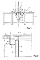
- FIG. 1 there is shown at 10 a table comprising at least one plate 12 supported by a frame 14 provided with feet.
- the plate 12 is circular and consists of a central panel supported by four legs and two side panels in a semi-circle each supported by two feet. These side panels are hinged to the central panel and their feet are pivotable and stored under the central panel to allow said side panels to fold.
- the plate 12 can have different shapes and be square, rectangular, circular or other. Similarly, different materials can be considered to achieve the plateau.
- the plate 12 can be in one piece as illustrated for example in FIG. 7, or comprise several parts as illustrated for example in FIG. 11A. In this case, some parts can slide in a substantially horizontal plane and at least a portion of the tray can retract under the sliding parts.
- the frame 14 may comprise rollers to facilitate the movement of the table.
- the table also comprises cooking means 16 disposed at a recess 18 formed at the plate 12, preferably in the center of said plate.
- the heat source of the cooking means 16 can be of the electric, gas, coal or other type.
- the cooking means 16 comprise a grill or a cooking plate 20 able to support the food to be cooked as well as a gas burner 22 placed under the plate or the grill 20.
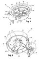
- the burner 22 comprises a central body 24, of hexagonal section for example, and at least one ramp 26, preferably ramps 26 attached at the side faces of the central body 24.
- Each ramp 26 comprises a plurality holes 28 reported along its length, preferably in a generatrix, through which the gas is likely to escape.
- the central body 24 comprises at the side faces, between the ramps 26, holes 30 through which the gas is able to escape to facilitate the lighting of the ramps 26.
- the central body 24 and the ramps 26 comprise inside ducts or recesses allowing the flow of gas from an inlet duct 32 connected to the central body to the various holes 28 and 30.
- At least one spark plug 34 may be provided near at least one ramp 26 to facilitate ignition.
- the cooking means 16 preferably comprise control means 36 for regulating the flow of gas, interposed between a gas reservoir 38 and the burner 22.
- control means 36 also make it possible to control the ignition of the candle 34.
- control means 36 are in the form of a housing 40 with at its upper face a first button 42 for controlling a gas inlet valve and a second button 44 for controlling the ignition of the candle 34.
- the upper surface of the housing 40 of the control means is disposed above or at the same level as the upper surface of the plate 12 of the table.
- the cooking means 16 comprise a cylinder 46 in which the burner 22 may be housed, as well as a ferrule 48 capable of adapting to the recess 18 formed at the level of the plate 12 and to be connected to said plate 12, the cylinder 46 and the ferrule 48 being connected by any appropriate means, in particular by means of lugs 50, and having diameters adapted to leave between them a substantially annular space.
- the cooking means are shown without the ferrule 48 in order to better see the cylinder 46.
- This annular space can channel a substantially cold air flow from below the table, can channel above the table hot air and fumes produced during cooking to reject them in height. This annular space thus generates a fictitious conduit.
- the air flow is produced naturally due to the temperature gradients and the appropriate heights of the shell 48 and the cylinder 46, as illustrated in FIG. 1.
- the ferrule has in the upper part a section shaped angle. Because of its shape, the ferrule 48 gives the table a good protection against the heat released by the cooking means.
- the cylinder 46 can be made from two concentric cylinders 46 'and 46 "between which are arranged columns 54.
- Each column 54 may comprise in the upper part a stud on which can rest the plate or grid 20.
- Providing two walls 46 ', 46 "separated by an air gap limits the heat diffusion to the guests and isolate the cooking means.
- the rising air flow between the shell 48 and the cylinder 46 reinforces the thermal insulation.
- the limited number of tabs 50 makes it possible to reduce thermal bridge phenomena in the direction of the plate.
- the ascending air flow between the shell 48 and the cylinder 46 contributes to cooling the tabs 50 and further reducing the thermal bridge phenomena.
- the cylinder 46 may comprise in the lower part a plate 56 for defining with the side walls of the cylinder 46 a housing in which the burner 22 may be arranged.
- the burner 22 can be connected to the cylinder 46 at one end of at least one ramp 26.
- the housing 40 of the control means is fixed to the cylinder 46, as illustrated in FIG.
- the ferrule 48 and the cylinder 46 are connected via tabs 50, preferably via three tabs 50, U-shaped with a first branch welded to the shell and another branch with a 90 ° bent end secured to a column 54.
- a grid 58 with shapes adapted to those of the annular space between the cylinder 46 and the ferrule 48 is provided, to avoid falling food under the table.
- this grid 58 is removable and rests on the base of the U of the tabs 50.
- this grid 58 is surmounted at its outer periphery with a cylindrical strip 60.
- This cylindrical strip 60 makes it possible firstly to serve as a transverse windbreaker in order to prevent the diffusion of heat towards the guests, and on the other hand to confine the hot air at the level of the cooking means 16.
- This cylindrical strip 60 may come in the extension of the ferrule 48 so as to provide a better channeling of the air flow.
- This cylindrical strip 60 may or may not overlap with the lower part of the shell 48.
- the height of the duct delimited by the shell 48 and the strip 60 is adapted to the height of the cylinder 46 to obtain a flow of ascending air in a natural way.
- the lower end portion of the shell 48 or the cylindrical strip 60 is shifted upwards by a height H relative to the lower end portion of the cylinder 46 to obtain a natural upward flow.
- the grid 58 and the cylindrical strip 60 are connected by any appropriate means.
- the connecting elements 50 between the ferrule 48 and the cylinder 46 allow a height adjustment of the cylinder 46 with respect to the ferrule in order to adjust the height of the cooking plate or grill 20 by compared to the plate 12 of the table.
- the cooking means are simple and relatively compact design allowing the table and equipped with to be relatively light compared to the tables of the prior art.
- this compactness of the cooking means contributes to making retractable at least part of the tray 12.
- the cooking means 16 can pivot relative to a substantially horizontal axis 62 connected to the frame 14 of the table, at least a portion of the plate being connected to the cooking means 16 so as to be pivotable relative to said frame.
- the entire plate 12 is connected to the cooking means 16 and can pivot with respect to the frame 14.
- the entire plate 12 is connected to the cooking means 16 and can pivot with respect to the frame 14.
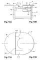
- FIGS. 10A, 10B, 11A and 11B only a portion 64 of the tray 12 is connected to the cooking means 16 so as to pivot relative to the frame 14.
- the frame 14 comprises four legs 66 each having in the upper part a stop 68 against which is likely to support the plate 12 and at least one arm 70 whose free end comprises a substantially vertical axis 72 pivotable relative to a support 74 attached to each end of the axis 62.
- the four feet are spaced relative to the axis 62, allowing the plate 12 to be in horizontal position against the abutments 68.
- the feet are arranged in the extension of the axis 62.
- the plateau 12 can pivot relative to the frame with the cooking means 16 which pivot relative to the axis 62, so as to occupy a vertical position. This configuration allows to retract the tray 12 to obtain a very compact table for storage.
- the frame may comprise only three feet, two pivoting at a first end of the axis 62, the third being disposed in the extension of the axis 62.
- the axis 62 is disposed between two feet 76.
- a lower crossbar also connects these two feet so as to form with the 76 feet and 62 axis a frame.
- Two more feet 78 are planned articulated with respect to this framework. Each foot comprises in the upper part a stop against which is likely to bear the plate 12 connected to the cooking means 16.
- the feet are arranged at 90 ° and the plate is in a horizontal position bearing against the feet 76 and 78.
- the feet 78 have pivoted so as to come against the feet 76.
- the plate 12 can pivot relative to the frame by means of the cooking means 16 which pivot about the axis 62, so as to occupy a substantially vertical position . This configuration allows to retract the tray 12 to obtain a very compact table for storage.
- the frame 12 comprises a horizontal frame 80 in the upper part supported by four feet 82, two parts 84 and 84 'of the plate being able to slide in a substantially horizontal plane. compared to box 80.
- the frame 80 supports an axis 62 around which can rotate the means 16 for cooking.
- An extension 64 is connected to the cooking means 16 and can occupy two positions, a first position in which it is arranged in the same plane as the sliding parts 84 and 84 ', as illustrated in FIGS. 10A and 11A, and a second position. after pivoting about the axis 62 in which it is disposed under the sliding parts 84 and 84 ', as shown in Figures 10B and 11B.
- said extension is made in three parts, a central portion 64.1 connected to the cooking means 16 and two side portions 64.2 pivotable relative at the lateral edges of the central part 64.1.
- the frame 14 comprises four feet 86 each having in the upper part a stop 88 against which is likely to support the plate 12 and at least one arm 90 pivotable relative to an axis 92 attached to each end of the axis 62.
- the four feet are spaced relative to the axis 62, allowing the plate 12 to be in horizontal position bearing against the stops 88.
- the feet 86 are arranged substantially in the extension. of the axis 62.
- the plate 12 can pivot relative to the frame by the cooking means 16 which pivot relative to the axis 62, so as to occupy a vertical position. This configuration allows to retract the tray 12 to obtain a very compact table for storage.
- the frame may comprise only three feet, two pivoting at a first end of the axis 62, the third being disposed in the extension of the axis 62.
- the variants illustrated in FIGS. 7, 8A, 8B, 9A, 9B, 10A, 10B, 11A, 11B, 12, 13A and 13B may comprise cooking means 16 as described in FIGS. 1 to 6 or different without annular conduit surrounding the heat source.
- the cooking means 16 described in Figures 1 to 6 can be reported on a fixed tray, non-retractable or having no retractable portion.
Landscapes
- Engineering & Computer Science (AREA)
- Chemical & Material Sciences (AREA)
- Combustion & Propulsion (AREA)
- Mechanical Engineering (AREA)
- General Engineering & Computer Science (AREA)
- Food Science & Technology (AREA)
- Baking, Grill, Roasting (AREA)
- Electric Ovens (AREA)
- Constitution Of High-Frequency Heating (AREA)
Applications Claiming Priority (1)
| Application Number | Priority Date | Filing Date | Title |
|---|---|---|---|
| FR0510157A FR2891445B1 (fr) | 2005-10-04 | 2005-10-04 | Table equipee de moyens de cuisson |
Publications (2)
| Publication Number | Publication Date |
|---|---|
| EP1772084A2 true EP1772084A2 (de) | 2007-04-11 |
| EP1772084A3 EP1772084A3 (de) | 2009-07-15 |
Family
ID=36735547
Family Applications (1)
| Application Number | Title | Priority Date | Filing Date |
|---|---|---|---|
| EP06362001A Withdrawn EP1772084A3 (de) | 2005-10-04 | 2006-10-03 | Kochmulde |
Country Status (2)
| Country | Link |
|---|---|
| EP (1) | EP1772084A3 (de) |
| FR (1) | FR2891445B1 (de) |
Cited By (3)
| Publication number | Priority date | Publication date | Assignee | Title |
|---|---|---|---|---|
| GB2454463A (en) * | 2007-11-06 | 2009-05-13 | Plancha Cooking Tables Ltd | Cooking station |
| CN105795716A (zh) * | 2016-05-10 | 2016-07-27 | 安徽坤昌家具有限公司 | 一种吃火锅用餐桌 |
| WO2017182769A1 (en) * | 2016-04-21 | 2017-10-26 | Craster Limited | Collapsible table |
Citations (7)
| Publication number | Priority date | Publication date | Assignee | Title |
|---|---|---|---|---|
| GB2059255A (en) * | 1979-09-05 | 1981-04-23 | Baveystock & Co Ltd A | A folding table and a frame therefor |
| DE3621100A1 (de) * | 1985-07-06 | 1987-01-08 | Gerhard Reitz | Grillvorrichtung |
| US4788905A (en) * | 1987-06-10 | 1988-12-06 | Kohorn H Von | Combination cooking, eating and ventilating system |
| DE4321646A1 (de) * | 1993-06-30 | 1995-01-12 | Kolb Alfred Ako | Klapptisch |
| JPH09108040A (ja) * | 1995-10-23 | 1997-04-28 | Sunoo P-Ku:Kk | テーブル |
| US20030192459A1 (en) * | 2002-04-16 | 2003-10-16 | Annas Timothy L. | Table with self-storing leaf |
| JP2004135725A (ja) * | 2002-10-16 | 2004-05-13 | Okamura Corp | 回動抵抗手段付き折り畳みテーブル |
Family Cites Families (5)
| Publication number | Priority date | Publication date | Assignee | Title |
|---|---|---|---|---|
| US3491744A (en) * | 1966-02-21 | 1970-01-27 | Kohorn H Von | Combination cooking and eating device |
| BE1001441A7 (fr) * | 1988-02-12 | 1989-10-31 | Nabulsi Aladin | Dispositif pour la cuisson d'aliments et meuble auquel est associe ce dispositif de cuisson. |
| AT395766B (de) * | 1989-11-24 | 1993-03-25 | Vaillant Gmbh | Vormischgasbrenner |
| JP4340828B2 (ja) * | 2000-08-21 | 2009-10-07 | 株式会社トルネックス | ロースター |
| JP3805328B2 (ja) * | 2003-07-03 | 2006-08-02 | 助川電気工業株式会社 | 排煙機能付ロースター |
-
2005
- 2005-10-04 FR FR0510157A patent/FR2891445B1/fr active Active
-
2006
- 2006-10-03 EP EP06362001A patent/EP1772084A3/de not_active Withdrawn
Patent Citations (7)
| Publication number | Priority date | Publication date | Assignee | Title |
|---|---|---|---|---|
| GB2059255A (en) * | 1979-09-05 | 1981-04-23 | Baveystock & Co Ltd A | A folding table and a frame therefor |
| DE3621100A1 (de) * | 1985-07-06 | 1987-01-08 | Gerhard Reitz | Grillvorrichtung |
| US4788905A (en) * | 1987-06-10 | 1988-12-06 | Kohorn H Von | Combination cooking, eating and ventilating system |
| DE4321646A1 (de) * | 1993-06-30 | 1995-01-12 | Kolb Alfred Ako | Klapptisch |
| JPH09108040A (ja) * | 1995-10-23 | 1997-04-28 | Sunoo P-Ku:Kk | テーブル |
| US20030192459A1 (en) * | 2002-04-16 | 2003-10-16 | Annas Timothy L. | Table with self-storing leaf |
| JP2004135725A (ja) * | 2002-10-16 | 2004-05-13 | Okamura Corp | 回動抵抗手段付き折り畳みテーブル |
Cited By (4)
| Publication number | Priority date | Publication date | Assignee | Title |
|---|---|---|---|---|
| GB2454463A (en) * | 2007-11-06 | 2009-05-13 | Plancha Cooking Tables Ltd | Cooking station |
| WO2017182769A1 (en) * | 2016-04-21 | 2017-10-26 | Craster Limited | Collapsible table |
| US11297935B2 (en) | 2016-04-21 | 2022-04-12 | Craster Ltd. | Collapsible table |
| CN105795716A (zh) * | 2016-05-10 | 2016-07-27 | 安徽坤昌家具有限公司 | 一种吃火锅用餐桌 |
Also Published As
| Publication number | Publication date |
|---|---|
| EP1772084A3 (de) | 2009-07-15 |
| FR2891445B1 (fr) | 2010-05-07 |
| FR2891445A1 (fr) | 2007-04-06 |
Similar Documents
| Publication | Publication Date | Title |
|---|---|---|
| WO2013182808A2 (fr) | Ensemble de cuisson d'extérieur multifonction | |
| FR2764677A1 (fr) | Dispositif de chauffage pour terrasse | |
| EP2967254B1 (de) | Grill mit mindestens zwei abnehmbaren panelen | |
| EP1772084A2 (de) | Kochmulde | |
| EP2445381B1 (de) | Kochvorrichtung | |
| EP1215983B1 (de) | Toastgerät mit einer erhitzungsvorrichtung für brötchen oder gleichartige nahrungsmittel | |
| EP2512308A1 (de) | Gasgriller | |
| EP1811883B1 (de) | Kompakter umwandelbarer barbecue-grill | |
| EP1607030B1 (de) | Haushaltsgerät mit mindestens einem lösbaren Zubehör | |
| EP0626055B1 (de) | Kleiner ofen zum grillen von lebensmitteln auf den brennern der gasherde | |
| FR2711053A1 (fr) | Barbecue à gaz à cuisson réglable. | |
| EP3329185B1 (de) | Holzofen zur verwendung im freien | |
| EP3852587A1 (de) | Kochvorrichtung mit blas- und rührwärme | |
| FR2844173A1 (fr) | Cuisine exterieure avec table de cuisson | |
| EP1356237A1 (de) | Elektrischer kochherd mit schwenkbarem heizelement | |
| FR3018673A1 (fr) | Table d'hotes avec dispositif central de cuisson par contact | |
| BE1009235A6 (fr) | Four de cuisson a rayons infrarouges. | |
| FR3114735A1 (fr) | Dispositif de cuisson d’aliments | |
| FR2489132A1 (fr) | Ensemble de cuisson a feu vif | |
| FR3069424B1 (fr) | Table demontable et pliable equipee d'un systeme de cuisson | |
| EP1616501B1 (de) | Büromöbel mit konfigurierbarem Untergestell | |
| FR2873911A1 (fr) | Appareil de cuisson de type barbecue | |
| FR2747283A1 (fr) | Table comportant un appareil a griller encastre dans son plateau et recouvrable par une couverture affleurante | |
| WO2001034009A1 (fr) | Support de petits pains amovible et repliable pour grille-pain | |
| FR2788331A1 (fr) | Caisson de bruleurs avec des buses orientables par une tringle commune |
Legal Events
| Date | Code | Title | Description |
|---|---|---|---|
| PUAI | Public reference made under article 153(3) epc to a published international application that has entered the european phase |
Free format text: ORIGINAL CODE: 0009012 |
|
| AK | Designated contracting states |
Kind code of ref document: A2 Designated state(s): AT BE BG CH CY CZ DE DK EE ES FI FR GB GR HU IE IS IT LI LT LU LV MC NL PL PT RO SE SI SK TR |
|
| AX | Request for extension of the european patent |
Extension state: AL BA HR MK YU |
|
| PUAL | Search report despatched |
Free format text: ORIGINAL CODE: 0009013 |
|
| AK | Designated contracting states |
Kind code of ref document: A3 Designated state(s): AT BE BG CH CY CZ DE DK EE ES FI FR GB GR HU IE IS IT LI LT LU LV MC NL PL PT RO SE SI SK TR |
|
| AX | Request for extension of the european patent |
Extension state: AL BA HR MK RS |
|
| RIC1 | Information provided on ipc code assigned before grant |
Ipc: A47B 3/08 20060101ALI20090609BHEP Ipc: A47J 37/07 20060101ALI20090609BHEP Ipc: F24C 15/20 20060101AFI20090609BHEP |
|
| AKX | Designation fees paid | ||
| REG | Reference to a national code |
Ref country code: DE Ref legal event code: 8566 |
|
| STAA | Information on the status of an ep patent application or granted ep patent |
Free format text: STATUS: THE APPLICATION IS DEEMED TO BE WITHDRAWN |
|
| 18D | Application deemed to be withdrawn |
Effective date: 20100424 |