EP2444552B1 - Blasrohr für Blasgerät - Google Patents
Blasrohr für Blasgerät Download PDFInfo
- Publication number
- EP2444552B1 EP2444552B1 EP11186102.7A EP11186102A EP2444552B1 EP 2444552 B1 EP2444552 B1 EP 2444552B1 EP 11186102 A EP11186102 A EP 11186102A EP 2444552 B1 EP2444552 B1 EP 2444552B1
- Authority
- EP
- European Patent Office
- Prior art keywords
- projections
- blower
- blower tube
- stage
- tube
- Prior art date
- Legal status (The legal status is an assumption and is not a legal conclusion. Google has not performed a legal analysis and makes no representation as to the accuracy of the status listed.)
- Not-in-force
Links
Images




Classifications
-
- E—FIXED CONSTRUCTIONS
- E01—CONSTRUCTION OF ROADS, RAILWAYS, OR BRIDGES
- E01H—STREET CLEANING; CLEANING OF PERMANENT WAYS; CLEANING BEACHES; DISPERSING OR PREVENTING FOG IN GENERAL CLEANING STREET OR RAILWAY FURNITURE OR TUNNEL WALLS
- E01H1/00—Removing undesirable matter from roads or like surfaces, with or without moistening of the surface
- E01H1/08—Pneumatically dislodging or taking-up undesirable matter or small objects; Drying by heat only or by streams of gas; Cleaning by projecting abrasive particles
- E01H1/0809—Loosening or dislodging by blowing ; Drying by means of gas streams
-
- A—HUMAN NECESSITIES
- A01—AGRICULTURE; FORESTRY; ANIMAL HUSBANDRY; HUNTING; TRAPPING; FISHING
- A01G—HORTICULTURE; CULTIVATION OF VEGETABLES, FLOWERS, RICE, FRUIT, VINES, HOPS OR SEAWEED; FORESTRY; WATERING
- A01G20/00—Cultivation of turf, lawn or the like; Apparatus or methods therefor
- A01G20/40—Apparatus for cleaning the lawn or grass surface
- A01G20/43—Apparatus for cleaning the lawn or grass surface for sweeping, collecting or disintegrating lawn debris
- A01G20/47—Vacuum or blower devices
Definitions
- the present invention relates to a blower tube for use with an air-blow work machine, which can reduce noises of the work machine in operation.
- the present invention also relates to an air-blow work machine equipped with such a blower tube.
- Patent Document 1 As known from Japanese Patent Laid-open Publication JP 2008-255877 (hereafter called Patent Document 1), air-blow work machines are known. Machines of this type are used to blow fallen leaves, rubbishes, waste cans, and so on, to clean the ground. They are generally called power blowers as often called in this application as well. These power blowers have a blower tube, which is typically a plastic mold, coupled to a blower main body. In operation, a high-speed airflow is blown out from the distal end of the blower tube. A user of such a power blower may direct the distal end of the blower tube toward fallen leaves, etc. on the ground to blow and gather them with a high-speed airflow from the blower tube.
- a blower tube which is typically a plastic mold
- While the power blower disclosed by the said Publication JP 2008-255877 is a hand-held one, also known are a backpack type power blower whose main body is carried on a user's back in operation (United States Patent No. 7,774,896 hereafter called Patent Document 2) and a stationary power blower whose main body is fixed stationary in operation.
- a blower tube according to the preamble of claim 1 is disclosed in US 2010/086412 A1 and US 6 324 720 B1 .
- Patent Document 2 proposes to interpose a sound-absorbing material between a frame and a drive source mounted on it.
- Noises of the power blower include one caused by ejection of the high-speed airflow from the distal end of the blower tube in operation. As this noise is a great nuisance to the ambient, there is a demand for a technology capable of reducing noises at the distal end of the blower tube.
- a further object of the present invention is to provide a blower tube for an air-blow work machine, which can reduce noises caused by ejection of a high-speed airflow from the blower tube by employing a special design at the distal end portion of the blower tube, and to provide such an air-blow work machine equipped with the blower tube.
- a yet further object of the present invention is to provide a blower tube for an air-blow work machine, which can reduce noises caused by ejection of a high-speed airflow from the blower tube by complicating frequency bands of the noises cause by ejection of a high-speed airflow from the blower tube, arid to provide such an air-blow work machine equipped with the blower tube.
- the projections provided at the distal end portion of the blower tube mingle the high-speed airflow to be released from the blower tube. Thereby, the projections can change the frequency bands of noises to more complicated frequency bands and thereby can reduce the noises.
- the projections are preferably in an odd number. This is based upon a result of an experiment that will be explained later.
- FIGS. 1 and 2 show a hand-held power blower taken as an embodiment of the air-blow work machine according to the present invention.
- FIG. 1 is a side elevational view of the hand-held power blower
- FIG. 2 is the cross-sectional view of a blower main body of the power blower.
- the hand-held power blower 100 comprises a blower main body 2 and a blower tube 4 detachably coupled to the blower main body 2.
- the blower main body 2 houses a compact-sized internal combustion engine as a drive source ( FIG. 2 ).
- the internal combustion engine 6 used in this embodiment is an air-cooled two-stroke single-cylinder internal combustion engine, but a four-stroke engine is usable instead.
- the blower main body 2 has a centrifugal air-blasting mechanism driven by the internal combustion engine 6.
- a high-speed airflow B ( FIG. 2 ) generated by the centrifugal air-blasting mechanism 8 is supplied to the blower tube 4 and released outside from the distal end of the blower tube 4.
- a user can operate a throttle trigger (not shown) with a finger to control the output of the internal combustion engine 6.
- the user can control the volume and flow rate of the high-speed airflow discharged from the blower tube 4 by manipulating the throttle trigger with his/her finger.
- the centrifugal air-blasting mechanism 8 includes a fan case 16 having an air inlet 14 for the blower and a centrifugal fan 18 contained in the fan case 18.
- the centrifugal fan 18 is connected to one end of the output shaft 20 of the internal combustion engine 6.
- a recoil starter 22 By manipulating a recoil starter 22, the user can activate the internal combustion engine 6.
- reference numeral 24 denotes a muffler and reference numeral 26 designates a fuel tank.
- the centrifugal fan 18 is driven. Under high-speed rotation of the centrifugal fan 18, external air A taken through the blower-use air inlet 14 is discharged from an air-blast port 30. The high-speed airflow B supplied to the air-blast port 30 is discharged externally through the blower tube 4.
- the blower tube 4 is composed of a tube main body 42 detachably coupled to the blower main body 2 and an attachment 44 detachably attached to the distal end portion of the tube main body 42. Both the tube main body 42 and the attachment 44 are plastic resin molds.
- the tube main body 42 has an elongated cylindrical form extending straight and having a circular cross-section.
- the distal end portion 42a of the tube main body 42 gradually diminishes in diameter toward its distal end, i.e. the front end ( FIG. 5 ).
- the attachment 44 has a cylindrical form having a circular cross section with a diameter approximate to the diameter of the outer circumferential diameter of the tube main body 42.
- the distal end of the blower tube 4 in this embodiment has the first forward-tapered portion defined by the distal end portion 44a of the attachment 44 and the second portion that is preferably tapered toward its distal (front) edge and slightly apart in the upstream side from the distal end portion 44a of the attachment 44 in the axial direction of the blower tube 4.
- the distal end portion 42a of the tube main body 42 may be non-tapered toward the front edge and equal in inner diameter throughout its entire length up to its front (distal) edge.
- the attachment 44 may not have the forward-tapered shape at its distal end portion 44a and may be equal in inner diameter throughout the entire length of the front (distal) end portion up to its front edge.
- the front end portion 42a of the tube body 42 having the forward-tapered configuration and the front end portion 44a of the attachment 44 having the forward-tapered configuration have projections at three positions to protrude radially inward toward the axial line of the blower tube 4.
- the three projections of the front end portion 42 of the tube main body 42 are referred to as first projections 46 and those of the attachment 44 are referred to as second projections 48.
- Each of the first and second projections preferably has the form of an isosceles triangle in its front plane.
- the three first projections 46 of the tube main body 42 are located at equal intervals in the circumferential direction, namely, at intervals of 120 degrees ( FIGS. 4 and 5 ).
- the three second projections 48 of the attachment 44 are located at equal intervals in the circumferential direction, namely, at intervals of 120 degrees ( FIGS. 4 and 5 ).
- FIG. 6A through 6F illustrate a variety of front-view configurations for the first and second projections 46 (48).
- the first and second projections 46 (48) may be trapezoidal in their front view as shown in FIG. 6A or dome-shaped as shown in FIG. 6B .
- the first and second projections 46 (48) may have the form of a scalene triangle in which two sides other than the base are not equal in their front view as shown in FIG. 6C , or may define an arch at its top as shown in FIG. 6D .
- two sides of each projection 46 (48) defining the vertex may be arcuate as shown in FIG. 6E . While the two sides of the projection 46 (48) shown in FIG.
- the convex need not be a point and may define a plane either flat or curved in the front view of the blower tube 4 as shown in FIG. 6F .
- each of the first and second projections 46, 48 having the front-view shape of an isosceles triangle is in form of a notch that is an inward indent in the wall of the tube main body 42 or the attachment 44 toward the axial line of the tube main body 42 or the attachment 44.
- each projection 46 (48) it is sufficient for each projection 46 (48) to protrude in a generally triangular shape into the circular cross-sectional inner passage of the tube main body 42 or the attachment 44 toward the axial line of the inner passage. Therefore, the first and second projections 46 may be solid instead of being hollow. This is applicable to the variety of their shapes shown in FIGS. 6A through 6F as well.
- the first and second projections 46 (48) may be used typically in combination of the isosceles front-view configurations as shown in FIGS. 3 to 5 . Otherwise, any combinations with any desired one from the configurations shown in FIGS. 6A through 6F may be employed as well.
- Each of the first and second projections 46, 48 in form of the isosceles triangle in its front view has a three-dimensional configuration with a ridge line 46a (48a) extending in parallel to the axial line of the airflow passage in the blower tube 4 ( FIG. 4 ) and gradually decreasing in height H ( FIG. 4 ) in the upstream direction of the airflow in the blower tube 4.
- the first projections 46 and the second projections 48 may be equal to or different from one another other in height H.
- first and second projections 46 and 48 in the triangular configuration in their frontal view are integrally molded with the tube main body 42 and the attachment 44 respectively.
- first and/or second projections 46 (48) may be prepared as separate elements to be bonded to the inner circumferential wall of the forward-tapered portions 42a (44a) of the tube main body 42 (attachment 44). This is applicable to the variety of configurations of the projections 46 (48) shown in FIGS. 6A through 6F as well.
- the blower tube 4 may be made in form of a unitary element having both the forward-tapered portions 42a, 44a by incorporating both the tube main body 42 and the attachment 44 in a unitary mold.
- the blower tube 4 may include both the three first projections 46 at the forward-tapered portion 42a and the three projections 48 of the forward-tapered portion 44a as its integral parts.
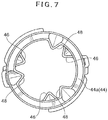
- the three first projections 46 on the tube body 42 and the three second projections 48 on the attachment 44 are preferably positioned in different phases such that they appear in an alternate order when viewed from the front face of the blower tube 4. More specifically, the second projections 48 of the attachment 44 are preferably off the phase of the first projections 46 by 60 degrees equally.
- a lock mechanism 50 for positional fixture of the attachment 44 relative to the tube main body 42 includes a positioning mechanism comprising one or more depressions 52 and complementary protuberances 54 that can get in engagement with the depressions 52 at a proper relative position in their circumferential direction.
- first and second projections 46 and 48 may be positioned in the same phase to overlap one another. When they are set not to overlap as explained above, distances between the projections need not be equal 60 degrees ( FIG. 7 ).
- FIG. 8 demonstrates that there was a noise reduction effect in the audible frequency band.
- noise levels are shown in dB(A) that is an A-weighted dB value
- white plots show values measured with conventional or existing blower tubes
- black plots show values measured with blower tubes having two sets of projections (46, 48) in two stages.
- noises caused by ejection of high-speed airflows from the blower tube 4 were measured through a microphone set a position distant from the blower tube 4 by three meters (3 m).
- blower tubes 4 with their attachments being removed which were different in number of the first projections 46 on their tube main bodies 42, each said projection 46 being in form of an isosceles triangle in its front view
- Diameter of the blower tubes 4 were 72 mm.
- an existing blower tube (having a forward-tapered distal end portion) without projections 46 was used.
- the samples had forward-tapered portions at the distal end portions 42a, and the first projections 46 (each in form of an isosceles triangle in its front view) were formed at the forward-tapered portions.
- CFM is an abbreviation of "cubic feet per minute” that herein pertains to the volume of airstream (volume of airflow) discharged from the distal end of each blower tube 4 per minute.
- MPH is an abbreviation of "miles per hour” that herein pertains to the velocity of the airstream (flow rate of air) discharged from the distal end of the blower tube 4. Changes in noise level were calculated based on the noise level of the existing blower tube.
- samples with odd number of projections 46 namely, the sample with three projections 46 and the sample with five projections 46 exhibited certain effects of noise reduction.
- samples with even numbers of projections 46 namely, the sample with four projections 46 and the sample with six projections 46 exhibited high noise levels.
- noise levels are affected by the inner diameter of the blower tube 4, volume and flow rate of the airstream from the blower tube 4, certain effects of noise reduction may be obtained even when with an even number of projections 46.
- the optimal level is considered to vary mainly with the volume and velocity of the high-speed airflow discharged from the blower tube 4.
- a reference sample in which the projections 46 have a height H provisionally considered optimum while fixing the number of projections 46 to three.
- the projections 46 of the blower tubes 4 used in the second experiment were in form of an isosceles triangle in their front view like in the first experiment.
- TABLE 3 shows a result of measurement of changes in noise level by changing the number of stages of the projections 46 and 48. Additionally, a sample blower tube 4 with three more projections in a third stage was prepared for the third experiment.
- blower tubes 4 used in the third experiment included tube main bodies 42 each having a forward-tapered end portions and that the attachments 44 used were also tapered toward their front (distal) ends.
- the blower tube 4 exhibits a certain effect of noise reduction even with the projections in only one stage but it exhibits highest effects when having the sets of projections 46, 48 in two different stages spaced apart from each other in the flow direction of the high-speed airflow in the blower tube 4.
- the blower tube 4 having three sets of projections in three different stages also exhibits a higher effect of noise reduction than the blower tube 4 having only one set of projections in one stage.
- all projections were in form of an isosceles triangle in their front view.
- the fourth experiment was carried out to confirm any difference in effect of noise reduction by changes in height H1 of the first projections 46 and height H2 of the second projections 48.
- a sample with three projections 48 of a standard height in the first stage and three projections 46 of a standard height in the second stage was prepared. Further, samples with various combinations of projections of the standard heights, higher projections and lower projections were prepared. With these samples, effects of noise reduction were evaluated.
- the power blower 100 exhibits a good effect of noise reduction when it has at least two stages of projections 46 (48) at the distal (front) end portion of the blower tube 4 and when the projections 46 (48) in each stage are in an odd number.
- the projections 46 (48) provided at distal end portions of the blower tube 4 interfere a high-speed airflow discharged in a spirally whirling fashion from the distal (front) end of the blower tube 4 and flowing through the blower tube 4.
- a radially outer portion of the high-speed airflow in the blower tube 4 flows spirally and hits the projections 46 (48).
- the radially outer portion of the high-speed airflow thereby changes its direction to an axial direction, and this may results in changing the frequency bands of the noises to more complicated frequency bands and thereby contributes to reduction of the noise level.
- a typical sound absorber is made of porous, flexible, synthetic sponge that may be urethane foam.
- the distal end portion 44a of the blower tube 4 With regard to the configuration of the distal end portion 44a of the blower tube 4, an equivalent effect of noise reduction can be obtained regardless either in the case that the distal end portion 44a (42a) is tapered to gradually diminish its diameter toward its front edge or in the case that the distal end portion 44a (42a) is uniform in diameter from its upstream end to the downstream end with respect to the airflow direction in the blower tube 4. It is also noted that tapering the distal end portion 44a to diminish its diameter toward its distal end contributes to changing the direction of the radially outer portion of the high-speed airflow discharged from the blower tube 4 to an axial direction and thereby enhances straightforwardness of the high-speed airflow discharged from the blower tube 4.
- the power blower 100 can be enhanced as well. Also when the power blower is provided with at least one stage of projections 48 (46), the outer diameter portion of the high-speed airflow flowing out of the blower tube 4 is changed in direction to a flow in parallel to the axial line, and the straightforwardness of the high-speed airflow from the blower tube 4 is enhanced.
- the present invention is applicable to portable air-blow work machines, backpack type ones and stationary one.
- the invention is applicable not only to air-blow work machines equipped with internal combustion engines as their drive sources but also to such work machines using motors as their drive sources.
Landscapes
- Life Sciences & Earth Sciences (AREA)
- Environmental Sciences (AREA)
- Engineering & Computer Science (AREA)
- Architecture (AREA)
- Civil Engineering (AREA)
- Structural Engineering (AREA)
- Structures Of Non-Positive Displacement Pumps (AREA)
Claims (9)
- Blasrohr (4), das lösbar an eine Luftblas-Arbeitsmaschine zu koppeln ist, die einen Blashauptkörper (2) aufweist, der einen durch eine Antriebsquelle (6) angetriebenen Luftgebläsemechanismus (8) aufnimmt, wobei das Blasrohr (4) bei Ankopplung an den Blashauptkörper (2) einen von dem Luftgebläsemechanismus (8) erzeugten Hochgeschwindigkeitsluftstrom (B) empfängt und diesen aus seinem distalen Endabschnitt (42a, 44a) nach außen abgibt, wobei das Blasrohr (4) umfasst:mehrere Vorsprünge (46, 48), die in Umfangsabständen an dem distalen Endabschnitt (42a, 44a) des Blasrohrs (4) so angeordnet sind, dass sie radial einwärts des Blasrohrs (4) vorstehen,dadurch gekennzeichnet, dass die Vorsprünge (46, 48) mindestens zwei Sätze von Vorsprüngen beinhalten, von denen sich ein Satz von Vorsprüngen (48) in einer an dem distalen Endabschnitt des Blasrohrs (4) angeordneten ersten Stufe befindet und sich ein anderer Satz von Vorsprüngen (46) in einer zweiten Stufe befindet, die von der ersten Stufe stromaufwärts bezüglich der Richtung des Hochgeschwindigkeitsluftstroms (B) in dem Blasrohr (4) distanziert ist.
- Blasrohr (4) nach Anspruch 1, wobei die mehreren Vorsprünge (46, 48) in einer ungeraden Anzahl vorliegen.
- Blasrohr (4) nach Anspruch 1, wobei der Satz von Vorsprüngen (48) in der ersten Stufe und der Satz von Vorsprüngen (46) in der zweiten Stufe die gleiche Zahl an Vorsprüngen aufweisen.
- Blasrohr (4) nach Anspruch 3, wobei die Zahl an Vorsprüngen (46, 48), die in dem genannten Satz von Vorsprüngen enthalten sind, jeweils in der ersten Stufe und der zweiten Stufe eine gerade Zahl ist.
- Blasrohr (4) nach Anspruch 3 oder 4, wobei die Vorsprünge (48) in der ersten Stufe und die Vorsprünge (46) in der zweiten Stufe derart phasenversetzt angeordnet sind, dass die Vorsprünge (48) in der ersten Stufe sich mit den Vorsprüngen (46) in der zweiten Stufe von vorne gesehen abzuwechseln scheinen.
- Blasrohr (4) nach Anspruch 5, wobei die Vorsprünge (48) in der ersten Stufe und die Vorsprünge (46) in der zweiten Stufe derart phasenversetzt angeordnet sind, dass sämtliche dieser Vorsprünge (46, 48) in gleichen Abständen erscheinen.
- Blasrohr (4) nach einem der Ansprüche 1 bis 6, wobei das Blasrohr (4) eine vergrößerte Kammer (4a) hat, die durch Vergrößern des Durchmessers eines mittleren Abschnittes des Blasrohrs (4) gebildet ist.
- Blasrohr (4) nach Anspruch 7, wobei ein Schalldämpfer (56) in der vergrößerten Kammer (4a) vorgesehen ist.
- Luftblas-Arbeitsmaschine (100) umfasssend:einen Blashauptkörper (2);einen Luftgebläsemechanismus (8), der in dem Blashauptkörper (2) aufgenommen ist, um einen Hochgeschwindigkeitsluftstrom (B) zu erzeugen;eine Antriebsquelle zum Antreiben des Luftgebläsemechanismus (8); undein Blasrohr (4) nach einem der Ansprüche 1 bis 8.
Applications Claiming Priority (1)
| Application Number | Priority Date | Filing Date | Title |
|---|---|---|---|
| JP2010238014A JP5572060B2 (ja) | 2010-10-22 | 2010-10-22 | 送風作業機 |
Publications (2)
| Publication Number | Publication Date |
|---|---|
| EP2444552A1 EP2444552A1 (de) | 2012-04-25 |
| EP2444552B1 true EP2444552B1 (de) | 2017-05-17 |
Family
ID=45062864
Family Applications (1)
| Application Number | Title | Priority Date | Filing Date |
|---|---|---|---|
| EP11186102.7A Not-in-force EP2444552B1 (de) | 2010-10-22 | 2011-10-21 | Blasrohr für Blasgerät |
Country Status (3)
| Country | Link |
|---|---|
| US (1) | US8789237B2 (de) |
| EP (1) | EP2444552B1 (de) |
| JP (1) | JP5572060B2 (de) |
Families Citing this family (18)
| Publication number | Priority date | Publication date | Assignee | Title |
|---|---|---|---|---|
| CN104250957A (zh) * | 2013-06-26 | 2014-12-31 | 苏州宝时得电动工具有限公司 | 吹吸装置 |
| JP6358833B2 (ja) * | 2014-04-03 | 2018-07-18 | 株式会社やまびこ | 背負式作業機 |
| JP6437745B2 (ja) * | 2014-06-20 | 2018-12-12 | 株式会社マキタ | ノズル |
| CN107645907B (zh) * | 2015-05-28 | 2021-01-29 | 胡斯华纳有限公司 | 改善的声音减小的鼓风机 |
| US20170231163A1 (en) * | 2016-02-16 | 2017-08-17 | Tti (Macao Commercial Offshore) Limited | Blower tube with lateral openings |
| US11206961B2 (en) * | 2017-03-08 | 2021-12-28 | Kyocera Industrial Tools Corporation | Sound absorption structure for air flow path in electric air flow generation device and electric vacuum |
| US11695312B2 (en) | 2017-09-01 | 2023-07-04 | Milwaukee Electric Tool Corporation | Electrostatic discharge dissipation structure |
| US11523569B2 (en) * | 2018-11-26 | 2022-12-13 | Black & Decker, Inc. | Concentrator attachment for blower air tube |
| AU2020205211B2 (en) | 2019-08-02 | 2026-01-15 | Techtronic Cordless Gp | Blowers having noise reduction features |
| JP2021080851A (ja) * | 2019-11-15 | 2021-05-27 | 株式会社マキタ | ブロワ |
| CN214742186U (zh) | 2020-01-21 | 2021-11-16 | 创科无线普通合伙 | 鼓风机 |
| AU2020286200A1 (en) | 2020-01-21 | 2021-08-05 | Techtronic Cordless Gp | Power tool having noise reduction features |
| USD1077859S1 (en) | 2020-11-17 | 2025-06-03 | Milwaukee Electric Tool Corporation | Blower |
| US11889794B2 (en) | 2020-12-30 | 2024-02-06 | Milwaukee Electric Tool Corporation | Handheld blower |
| EP4042861B1 (de) * | 2021-02-12 | 2023-12-20 | Andreas Stihl AG & Co. KG | Schutzvorrichtung für einen ansaug- oder blaskanal eines arbeitsgerätes und arbeitsgerät mit einer schutzvorrichtung |
| DE112022003963T5 (de) | 2021-10-11 | 2024-07-04 | Milwaukee Electric Tool Corporation | Gebläse für ein handgeführtes blasgerät |
| US12352274B2 (en) | 2022-03-21 | 2025-07-08 | Milwaukee Electric Tool Corporation | Axial blower |
| USD1003551S1 (en) * | 2023-07-06 | 2023-10-31 | Dongguan le selling Trade Co. Ltd. | Air nozzle for a leaf blower |
Family Cites Families (16)
| Publication number | Priority date | Publication date | Assignee | Title |
|---|---|---|---|---|
| JPS61171519A (ja) * | 1985-01-23 | 1986-08-02 | Komatsu Zenoa Kk | 集塵装置 |
| US4723893A (en) * | 1985-07-10 | 1988-02-09 | 501 Komatsu Zenoah Company | Portable blower |
| JP2641186B2 (ja) * | 1991-07-18 | 1997-08-13 | 株式会社荏原製作所 | 空気等の低騒音形吹き出し口 |
| JP3883604B2 (ja) | 1996-04-24 | 2007-02-21 | 株式会社共立 | 消音装置付ブロワパイプ |
| JP3437894B2 (ja) * | 1996-07-01 | 2003-08-18 | 株式会社共立 | ブロワパイプへの消音装置の取付方法 |
| US6158082A (en) * | 1998-03-10 | 2000-12-12 | The Toro Company | Portable blower with blower tube noise reduction |
| US6105206A (en) * | 1999-04-13 | 2000-08-22 | Department Of Water And Power City Of Los Angeles | Portable electrically powered blower apparatus |
| JP2001289026A (ja) * | 2000-04-05 | 2001-10-19 | Komatsu Zenoah Co | 吸音材付風管 |
| JP3672828B2 (ja) * | 2001-02-06 | 2005-07-20 | 株式会社丸山製作所 | 空気吐出型清掃機の送風管 |
| JP2003108144A (ja) * | 2001-09-28 | 2003-04-11 | Mitsubishi Heavy Ind Ltd | 流力騒音低減装置 |
| US6658839B2 (en) | 2002-02-28 | 2003-12-09 | The Boeing Company | Convergent/divergent segmented exhaust nozzle |
| DE102005003275A1 (de) | 2005-01-25 | 2006-07-27 | Andreas Stihl Ag & Co. Kg | Rückentragbares Saug-/Blasgerät |
| US20100086412A1 (en) | 2006-10-13 | 2010-04-08 | Shindaiwa Corporation | Blower |
| JP4830836B2 (ja) * | 2006-12-18 | 2011-12-07 | 株式会社Ihi | ジェット噴流排気ノズル及びジェットエンジン |
| JP4899033B2 (ja) | 2007-04-04 | 2012-03-21 | 株式会社やまびこ | 送風作業機及び送風機のケーシング |
| GB0819608D0 (en) | 2008-10-24 | 2008-12-03 | Mosen Ltd | Improved tunnel ventilation device |
-
2010
- 2010-10-22 JP JP2010238014A patent/JP5572060B2/ja active Active
-
2011
- 2011-10-21 US US13/278,250 patent/US8789237B2/en active Active
- 2011-10-21 EP EP11186102.7A patent/EP2444552B1/de not_active Not-in-force
Non-Patent Citations (1)
| Title |
|---|
| None * |
Also Published As
| Publication number | Publication date |
|---|---|
| JP5572060B2 (ja) | 2014-08-13 |
| US8789237B2 (en) | 2014-07-29 |
| JP2012092655A (ja) | 2012-05-17 |
| EP2444552A1 (de) | 2012-04-25 |
| US20120096672A1 (en) | 2012-04-26 |
Similar Documents
| Publication | Publication Date | Title |
|---|---|---|
| US8789237B2 (en) | Air-blow work machine | |
| US6514036B2 (en) | Radial flow fan with impeller having blade configuration for noise reduction | |
| US7739773B2 (en) | Portable blower | |
| US8888440B2 (en) | Compressor of exhaust gas turbocharger | |
| US6468053B2 (en) | Blower | |
| JP5620690B2 (ja) | ブロワ | |
| US9206567B2 (en) | Air-blow working machine | |
| US20100322779A1 (en) | Propeller fan | |
| US20190136866A1 (en) | Blower impeller for a handheld blower | |
| WO2022147300A1 (en) | Handheld blower | |
| JP2006002767A (ja) | 消音装置 | |
| EP1361367A3 (de) | Turbolüfter und Klimaanlage mit einem solchen Lüfter | |
| CN110630540B (zh) | 电动送风机及电动吸尘器 | |
| CN1749579B (zh) | 具有承载框架的鼓风机 | |
| US20010021344A1 (en) | Centrifugal blower and portable power working machine | |
| CN109247877B (zh) | 吸尘器及其电机模组 | |
| JP5340816B2 (ja) | 通気ダクト | |
| CN106438503B (zh) | 基座及无叶风扇 | |
| JP4448929B2 (ja) | 可搬式のブロワ | |
| WO2019146165A1 (ja) | 消音器 | |
| CN110345110A (zh) | 消音装置及应用该消音装置的换气扇 | |
| CN211834199U (zh) | 导流结构及吸尘器 | |
| JP2011017291A (ja) | 吸気装置 | |
| US20060093479A1 (en) | Pressure-boosting axial-flow heat-dissipating fan | |
| JP2000107104A (ja) | 携帯用掃除機の可撓性ホース |
Legal Events
| Date | Code | Title | Description |
|---|---|---|---|
| AK | Designated contracting states |
Kind code of ref document: A1 Designated state(s): AL AT BE BG CH CY CZ DE DK EE ES FI FR GB GR HR HU IE IS IT LI LT LU LV MC MK MT NL NO PL PT RO RS SE SI SK SM TR |
|
| AX | Request for extension of the european patent |
Extension state: BA ME |
|
| PUAI | Public reference made under article 153(3) epc to a published international application that has entered the european phase |
Free format text: ORIGINAL CODE: 0009012 |
|
| 17P | Request for examination filed |
Effective date: 20121025 |
|
| 17Q | First examination report despatched |
Effective date: 20160805 |
|
| GRAP | Despatch of communication of intention to grant a patent |
Free format text: ORIGINAL CODE: EPIDOSNIGR1 |
|
| STAA | Information on the status of an ep patent application or granted ep patent |
Free format text: STATUS: GRANT OF PATENT IS INTENDED |
|
| INTG | Intention to grant announced |
Effective date: 20161123 |
|
| GRAS | Grant fee paid |
Free format text: ORIGINAL CODE: EPIDOSNIGR3 |
|
| GRAJ | Information related to disapproval of communication of intention to grant by the applicant or resumption of examination proceedings by the epo deleted |
Free format text: ORIGINAL CODE: EPIDOSDIGR1 |
|
| GRAL | Information related to payment of fee for publishing/printing deleted |
Free format text: ORIGINAL CODE: EPIDOSDIGR3 |
|
| STAA | Information on the status of an ep patent application or granted ep patent |
Free format text: STATUS: EXAMINATION IS IN PROGRESS |
|
| GRAR | Information related to intention to grant a patent recorded |
Free format text: ORIGINAL CODE: EPIDOSNIGR71 |
|
| STAA | Information on the status of an ep patent application or granted ep patent |
Free format text: STATUS: GRANT OF PATENT IS INTENDED |
|
| GRAA | (expected) grant |
Free format text: ORIGINAL CODE: 0009210 |
|
| STAA | Information on the status of an ep patent application or granted ep patent |
Free format text: STATUS: THE PATENT HAS BEEN GRANTED |
|
| INTC | Intention to grant announced (deleted) | ||
| AK | Designated contracting states |
Kind code of ref document: B1 Designated state(s): AL AT BE BG CH CY CZ DE DK EE ES FI FR GB GR HR HU IE IS IT LI LT LU LV MC MK MT NL NO PL PT RO RS SE SI SK SM TR |
|
| INTG | Intention to grant announced |
Effective date: 20170411 |
|
| REG | Reference to a national code |
Ref country code: GB Ref legal event code: FG4D |
|
| REG | Reference to a national code |
Ref country code: CH Ref legal event code: EP |
|
| REG | Reference to a national code |
Ref country code: IE Ref legal event code: FG4D |
|
| REG | Reference to a national code |
Ref country code: AT Ref legal event code: REF Ref document number: 894588 Country of ref document: AT Kind code of ref document: T Effective date: 20170615 |
|
| REG | Reference to a national code |
Ref country code: DE Ref legal event code: R096 Ref document number: 602011037986 Country of ref document: DE |
|
| REG | Reference to a national code |
Ref country code: NL Ref legal event code: MP Effective date: 20170517 |
|
| REG | Reference to a national code |
Ref country code: LT Ref legal event code: MG4D |
|
| REG | Reference to a national code |
Ref country code: AT Ref legal event code: MK05 Ref document number: 894588 Country of ref document: AT Kind code of ref document: T Effective date: 20170517 |
|
| REG | Reference to a national code |
Ref country code: FR Ref legal event code: PLFP Year of fee payment: 7 |
|
| PG25 | Lapsed in a contracting state [announced via postgrant information from national office to epo] |
Ref country code: NO Free format text: LAPSE BECAUSE OF FAILURE TO SUBMIT A TRANSLATION OF THE DESCRIPTION OR TO PAY THE FEE WITHIN THE PRESCRIBED TIME-LIMIT Effective date: 20170817 Ref country code: FI Free format text: LAPSE BECAUSE OF FAILURE TO SUBMIT A TRANSLATION OF THE DESCRIPTION OR TO PAY THE FEE WITHIN THE PRESCRIBED TIME-LIMIT Effective date: 20170517 Ref country code: HR Free format text: LAPSE BECAUSE OF FAILURE TO SUBMIT A TRANSLATION OF THE DESCRIPTION OR TO PAY THE FEE WITHIN THE PRESCRIBED TIME-LIMIT Effective date: 20170517 Ref country code: LT Free format text: LAPSE BECAUSE OF FAILURE TO SUBMIT A TRANSLATION OF THE DESCRIPTION OR TO PAY THE FEE WITHIN THE PRESCRIBED TIME-LIMIT Effective date: 20170517 Ref country code: GR Free format text: LAPSE BECAUSE OF FAILURE TO SUBMIT A TRANSLATION OF THE DESCRIPTION OR TO PAY THE FEE WITHIN THE PRESCRIBED TIME-LIMIT Effective date: 20170818 Ref country code: ES Free format text: LAPSE BECAUSE OF FAILURE TO SUBMIT A TRANSLATION OF THE DESCRIPTION OR TO PAY THE FEE WITHIN THE PRESCRIBED TIME-LIMIT Effective date: 20170517 Ref country code: AT Free format text: LAPSE BECAUSE OF FAILURE TO SUBMIT A TRANSLATION OF THE DESCRIPTION OR TO PAY THE FEE WITHIN THE PRESCRIBED TIME-LIMIT Effective date: 20170517 |
|
| PG25 | Lapsed in a contracting state [announced via postgrant information from national office to epo] |
Ref country code: BG Free format text: LAPSE BECAUSE OF FAILURE TO SUBMIT A TRANSLATION OF THE DESCRIPTION OR TO PAY THE FEE WITHIN THE PRESCRIBED TIME-LIMIT Effective date: 20170817 Ref country code: IS Free format text: LAPSE BECAUSE OF FAILURE TO SUBMIT A TRANSLATION OF THE DESCRIPTION OR TO PAY THE FEE WITHIN THE PRESCRIBED TIME-LIMIT Effective date: 20170917 Ref country code: NL Free format text: LAPSE BECAUSE OF FAILURE TO SUBMIT A TRANSLATION OF THE DESCRIPTION OR TO PAY THE FEE WITHIN THE PRESCRIBED TIME-LIMIT Effective date: 20170517 Ref country code: RS Free format text: LAPSE BECAUSE OF FAILURE TO SUBMIT A TRANSLATION OF THE DESCRIPTION OR TO PAY THE FEE WITHIN THE PRESCRIBED TIME-LIMIT Effective date: 20170517 Ref country code: LV Free format text: LAPSE BECAUSE OF FAILURE TO SUBMIT A TRANSLATION OF THE DESCRIPTION OR TO PAY THE FEE WITHIN THE PRESCRIBED TIME-LIMIT Effective date: 20170517 Ref country code: SE Free format text: LAPSE BECAUSE OF FAILURE TO SUBMIT A TRANSLATION OF THE DESCRIPTION OR TO PAY THE FEE WITHIN THE PRESCRIBED TIME-LIMIT Effective date: 20170517 Ref country code: PL Free format text: LAPSE BECAUSE OF FAILURE TO SUBMIT A TRANSLATION OF THE DESCRIPTION OR TO PAY THE FEE WITHIN THE PRESCRIBED TIME-LIMIT Effective date: 20170517 |
|
| PG25 | Lapsed in a contracting state [announced via postgrant information from national office to epo] |
Ref country code: EE Free format text: LAPSE BECAUSE OF FAILURE TO SUBMIT A TRANSLATION OF THE DESCRIPTION OR TO PAY THE FEE WITHIN THE PRESCRIBED TIME-LIMIT Effective date: 20170517 Ref country code: CZ Free format text: LAPSE BECAUSE OF FAILURE TO SUBMIT A TRANSLATION OF THE DESCRIPTION OR TO PAY THE FEE WITHIN THE PRESCRIBED TIME-LIMIT Effective date: 20170517 Ref country code: RO Free format text: LAPSE BECAUSE OF FAILURE TO SUBMIT A TRANSLATION OF THE DESCRIPTION OR TO PAY THE FEE WITHIN THE PRESCRIBED TIME-LIMIT Effective date: 20170517 Ref country code: SK Free format text: LAPSE BECAUSE OF FAILURE TO SUBMIT A TRANSLATION OF THE DESCRIPTION OR TO PAY THE FEE WITHIN THE PRESCRIBED TIME-LIMIT Effective date: 20170517 Ref country code: DK Free format text: LAPSE BECAUSE OF FAILURE TO SUBMIT A TRANSLATION OF THE DESCRIPTION OR TO PAY THE FEE WITHIN THE PRESCRIBED TIME-LIMIT Effective date: 20170517 |
|
| REG | Reference to a national code |
Ref country code: DE Ref legal event code: R097 Ref document number: 602011037986 Country of ref document: DE |
|
| PG25 | Lapsed in a contracting state [announced via postgrant information from national office to epo] |
Ref country code: SM Free format text: LAPSE BECAUSE OF FAILURE TO SUBMIT A TRANSLATION OF THE DESCRIPTION OR TO PAY THE FEE WITHIN THE PRESCRIBED TIME-LIMIT Effective date: 20170517 Ref country code: IT Free format text: LAPSE BECAUSE OF FAILURE TO SUBMIT A TRANSLATION OF THE DESCRIPTION OR TO PAY THE FEE WITHIN THE PRESCRIBED TIME-LIMIT Effective date: 20170517 |
|
| PLBE | No opposition filed within time limit |
Free format text: ORIGINAL CODE: 0009261 |
|
| STAA | Information on the status of an ep patent application or granted ep patent |
Free format text: STATUS: NO OPPOSITION FILED WITHIN TIME LIMIT |
|
| 26N | No opposition filed |
Effective date: 20180220 |
|
| PG25 | Lapsed in a contracting state [announced via postgrant information from national office to epo] |
Ref country code: SI Free format text: LAPSE BECAUSE OF FAILURE TO SUBMIT A TRANSLATION OF THE DESCRIPTION OR TO PAY THE FEE WITHIN THE PRESCRIBED TIME-LIMIT Effective date: 20170517 Ref country code: MC Free format text: LAPSE BECAUSE OF FAILURE TO SUBMIT A TRANSLATION OF THE DESCRIPTION OR TO PAY THE FEE WITHIN THE PRESCRIBED TIME-LIMIT Effective date: 20170517 |
|
| REG | Reference to a national code |
Ref country code: CH Ref legal event code: PL |
|
| GBPC | Gb: european patent ceased through non-payment of renewal fee |
Effective date: 20171021 |
|
| REG | Reference to a national code |
Ref country code: IE Ref legal event code: MM4A |
|
| PG25 | Lapsed in a contracting state [announced via postgrant information from national office to epo] |
Ref country code: CH Free format text: LAPSE BECAUSE OF NON-PAYMENT OF DUE FEES Effective date: 20171031 Ref country code: GB Free format text: LAPSE BECAUSE OF NON-PAYMENT OF DUE FEES Effective date: 20171021 Ref country code: LU Free format text: LAPSE BECAUSE OF NON-PAYMENT OF DUE FEES Effective date: 20171021 Ref country code: LI Free format text: LAPSE BECAUSE OF NON-PAYMENT OF DUE FEES Effective date: 20171031 |
|
| PG25 | Lapsed in a contracting state [announced via postgrant information from national office to epo] |
Ref country code: MT Free format text: LAPSE BECAUSE OF NON-PAYMENT OF DUE FEES Effective date: 20171021 |
|
| REG | Reference to a national code |
Ref country code: FR Ref legal event code: PLFP Year of fee payment: 8 |
|
| PG25 | Lapsed in a contracting state [announced via postgrant information from national office to epo] |
Ref country code: IE Free format text: LAPSE BECAUSE OF NON-PAYMENT OF DUE FEES Effective date: 20171021 |
|
| PG25 | Lapsed in a contracting state [announced via postgrant information from national office to epo] |
Ref country code: HU Free format text: LAPSE BECAUSE OF FAILURE TO SUBMIT A TRANSLATION OF THE DESCRIPTION OR TO PAY THE FEE WITHIN THE PRESCRIBED TIME-LIMIT; INVALID AB INITIO Effective date: 20111021 |
|
| PG25 | Lapsed in a contracting state [announced via postgrant information from national office to epo] |
Ref country code: CY Free format text: LAPSE BECAUSE OF NON-PAYMENT OF DUE FEES Effective date: 20170517 |
|
| PG25 | Lapsed in a contracting state [announced via postgrant information from national office to epo] |
Ref country code: MK Free format text: LAPSE BECAUSE OF FAILURE TO SUBMIT A TRANSLATION OF THE DESCRIPTION OR TO PAY THE FEE WITHIN THE PRESCRIBED TIME-LIMIT Effective date: 20170517 |
|
| PGFP | Annual fee paid to national office [announced via postgrant information from national office to epo] |
Ref country code: DE Payment date: 20191021 Year of fee payment: 9 |
|
| PGFP | Annual fee paid to national office [announced via postgrant information from national office to epo] |
Ref country code: FR Payment date: 20191028 Year of fee payment: 9 Ref country code: BE Payment date: 20191021 Year of fee payment: 9 |
|
| PG25 | Lapsed in a contracting state [announced via postgrant information from national office to epo] |
Ref country code: TR Free format text: LAPSE BECAUSE OF FAILURE TO SUBMIT A TRANSLATION OF THE DESCRIPTION OR TO PAY THE FEE WITHIN THE PRESCRIBED TIME-LIMIT Effective date: 20170517 |
|
| PG25 | Lapsed in a contracting state [announced via postgrant information from national office to epo] |
Ref country code: PT Free format text: LAPSE BECAUSE OF FAILURE TO SUBMIT A TRANSLATION OF THE DESCRIPTION OR TO PAY THE FEE WITHIN THE PRESCRIBED TIME-LIMIT Effective date: 20170517 |
|
| PG25 | Lapsed in a contracting state [announced via postgrant information from national office to epo] |
Ref country code: AL Free format text: LAPSE BECAUSE OF FAILURE TO SUBMIT A TRANSLATION OF THE DESCRIPTION OR TO PAY THE FEE WITHIN THE PRESCRIBED TIME-LIMIT Effective date: 20170517 |
|
| REG | Reference to a national code |
Ref country code: DE Ref legal event code: R119 Ref document number: 602011037986 Country of ref document: DE |
|
| REG | Reference to a national code |
Ref country code: BE Ref legal event code: MM Effective date: 20201031 |
|
| PG25 | Lapsed in a contracting state [announced via postgrant information from national office to epo] |
Ref country code: DE Free format text: LAPSE BECAUSE OF NON-PAYMENT OF DUE FEES Effective date: 20210501 Ref country code: FR Free format text: LAPSE BECAUSE OF NON-PAYMENT OF DUE FEES Effective date: 20201031 |
|
| PG25 | Lapsed in a contracting state [announced via postgrant information from national office to epo] |
Ref country code: BE Free format text: LAPSE BECAUSE OF NON-PAYMENT OF DUE FEES Effective date: 20201031 |