EP2439105A2 - Beleuchtungsvorrichtung, insbesondere Leselampe - Google Patents
Beleuchtungsvorrichtung, insbesondere Leselampe Download PDFInfo
- Publication number
- EP2439105A2 EP2439105A2 EP20110181827 EP11181827A EP2439105A2 EP 2439105 A2 EP2439105 A2 EP 2439105A2 EP 20110181827 EP20110181827 EP 20110181827 EP 11181827 A EP11181827 A EP 11181827A EP 2439105 A2 EP2439105 A2 EP 2439105A2
- Authority
- EP
- European Patent Office
- Prior art keywords
- lighting device
- light source
- lid
- cover
- longitudinal axis
- Prior art date
- Legal status (The legal status is an assumption and is not a legal conclusion. Google has not performed a legal analysis and makes no representation as to the accuracy of the status listed.)
- Granted
Links
- 238000003860 storage Methods 0.000 claims abstract description 11
- 238000005286 illumination Methods 0.000 claims description 12
- 238000013016 damping Methods 0.000 claims description 5
- 238000003825 pressing Methods 0.000 claims description 5
- 230000003760 hair shine Effects 0.000 claims 1
- 238000009434 installation Methods 0.000 description 4
- 239000004417 polycarbonate Substances 0.000 description 4
- 239000004676 acrylonitrile butadiene styrene Substances 0.000 description 3
- 230000008901 benefit Effects 0.000 description 3
- 238000010276 construction Methods 0.000 description 3
- 230000006378 damage Effects 0.000 description 3
- 229920000515 polycarbonate Polymers 0.000 description 3
- 208000027418 Wounds and injury Diseases 0.000 description 2
- XECAHXYUAAWDEL-UHFFFAOYSA-N acrylonitrile butadiene styrene Chemical compound C=CC=C.C=CC#N.C=CC1=CC=CC=C1 XECAHXYUAAWDEL-UHFFFAOYSA-N 0.000 description 2
- 229920000122 acrylonitrile butadiene styrene Polymers 0.000 description 2
- 239000002318 adhesion promoter Substances 0.000 description 2
- 230000008859 change Effects 0.000 description 2
- 239000003063 flame retardant Substances 0.000 description 2
- 239000003365 glass fiber Substances 0.000 description 2
- 208000014674 injury Diseases 0.000 description 2
- 239000003973 paint Substances 0.000 description 2
- RNFJDJUURJAICM-UHFFFAOYSA-N 2,2,4,4,6,6-hexaphenoxy-1,3,5-triaza-2$l^{5},4$l^{5},6$l^{5}-triphosphacyclohexa-1,3,5-triene Chemical compound N=1P(OC=2C=CC=CC=2)(OC=2C=CC=CC=2)=NP(OC=2C=CC=CC=2)(OC=2C=CC=CC=2)=NP=1(OC=1C=CC=CC=1)OC1=CC=CC=C1 RNFJDJUURJAICM-UHFFFAOYSA-N 0.000 description 1
- VYZAMTAEIAYCRO-UHFFFAOYSA-N Chromium Chemical compound [Cr] VYZAMTAEIAYCRO-UHFFFAOYSA-N 0.000 description 1
- 239000004952 Polyamide Substances 0.000 description 1
- 238000005299 abrasion Methods 0.000 description 1
- 230000009471 action Effects 0.000 description 1
- 235000013361 beverage Nutrition 0.000 description 1
- 238000005229 chemical vapour deposition Methods 0.000 description 1
- 229910052804 chromium Inorganic materials 0.000 description 1
- 239000011651 chromium Substances 0.000 description 1
- 239000012459 cleaning agent Substances 0.000 description 1
- 239000011248 coating agent Substances 0.000 description 1
- 238000000576 coating method Methods 0.000 description 1
- 238000010168 coupling process Methods 0.000 description 1
- 238000005859 coupling reaction Methods 0.000 description 1
- 230000000694 effects Effects 0.000 description 1
- 230000020169 heat generation Effects 0.000 description 1
- 238000001746 injection moulding Methods 0.000 description 1
- 239000004922 lacquer Substances 0.000 description 1
- 238000004519 manufacturing process Methods 0.000 description 1
- 239000000463 material Substances 0.000 description 1
- 230000007246 mechanism Effects 0.000 description 1
- 238000000034 method Methods 0.000 description 1
- 239000000203 mixture Substances 0.000 description 1
- 230000003287 optical effect Effects 0.000 description 1
- 239000013307 optical fiber Substances 0.000 description 1
- 238000005192 partition Methods 0.000 description 1
- 239000012994 photoredox catalyst Substances 0.000 description 1
- 239000004033 plastic Substances 0.000 description 1
- 229920003023 plastic Polymers 0.000 description 1
- 229920002647 polyamide Polymers 0.000 description 1
- 230000008569 process Effects 0.000 description 1
- 235000020095 red wine Nutrition 0.000 description 1
- 230000009467 reduction Effects 0.000 description 1
- 230000002787 reinforcement Effects 0.000 description 1
- 238000005096 rolling process Methods 0.000 description 1
- 229910000679 solder Inorganic materials 0.000 description 1
- 239000012780 transparent material Substances 0.000 description 1
Images

Classifications
-
- B—PERFORMING OPERATIONS; TRANSPORTING
- B60—VEHICLES IN GENERAL
- B60Q—ARRANGEMENT OF SIGNALLING OR LIGHTING DEVICES, THE MOUNTING OR SUPPORTING THEREOF OR CIRCUITS THEREFOR, FOR VEHICLES IN GENERAL
- B60Q3/00—Arrangement of lighting devices for vehicle interiors; Lighting devices specially adapted for vehicle interiors
- B60Q3/70—Arrangement of lighting devices for vehicle interiors; Lighting devices specially adapted for vehicle interiors characterised by the purpose
- B60Q3/76—Arrangement of lighting devices for vehicle interiors; Lighting devices specially adapted for vehicle interiors characterised by the purpose for spotlighting, e.g. reading lamps
-
- B—PERFORMING OPERATIONS; TRANSPORTING
- B60—VEHICLES IN GENERAL
- B60Q—ARRANGEMENT OF SIGNALLING OR LIGHTING DEVICES, THE MOUNTING OR SUPPORTING THEREOF OR CIRCUITS THEREFOR, FOR VEHICLES IN GENERAL
- B60Q3/00—Arrangement of lighting devices for vehicle interiors; Lighting devices specially adapted for vehicle interiors
- B60Q3/40—Arrangement of lighting devices for vehicle interiors; Lighting devices specially adapted for vehicle interiors specially adapted for specific vehicle types
- B60Q3/41—Arrangement of lighting devices for vehicle interiors; Lighting devices specially adapted for vehicle interiors specially adapted for specific vehicle types for mass transit vehicles, e.g. buses
- B60Q3/44—Spotlighting, e.g. reading lamps
-
- B—PERFORMING OPERATIONS; TRANSPORTING
- B60—VEHICLES IN GENERAL
- B60Q—ARRANGEMENT OF SIGNALLING OR LIGHTING DEVICES, THE MOUNTING OR SUPPORTING THEREOF OR CIRCUITS THEREFOR, FOR VEHICLES IN GENERAL
- B60Q3/00—Arrangement of lighting devices for vehicle interiors; Lighting devices specially adapted for vehicle interiors
- B60Q3/50—Mounting arrangements
- B60Q3/57—Retractable or concealable lighting devices
-
- B—PERFORMING OPERATIONS; TRANSPORTING
- B60—VEHICLES IN GENERAL
- B60Q—ARRANGEMENT OF SIGNALLING OR LIGHTING DEVICES, THE MOUNTING OR SUPPORTING THEREOF OR CIRCUITS THEREFOR, FOR VEHICLES IN GENERAL
- B60Q3/00—Arrangement of lighting devices for vehicle interiors; Lighting devices specially adapted for vehicle interiors
- B60Q3/80—Circuits; Control arrangements
- B60Q3/82—Switches specially adapted for vehicle interior lighting, e.g. switching by tilting the lens
-
- B—PERFORMING OPERATIONS; TRANSPORTING
- B64—AIRCRAFT; AVIATION; COSMONAUTICS
- B64D—EQUIPMENT FOR FITTING IN OR TO AIRCRAFT; FLIGHT SUITS; PARACHUTES; ARRANGEMENTS OR MOUNTING OF POWER PLANTS OR PROPULSION TRANSMISSIONS IN AIRCRAFT
- B64D11/00—Passenger or crew accommodation; Flight-deck installations not otherwise provided for
- B64D2011/0053—Cabin passenger reading lights
Definitions
- the present invention relates to a lighting device, in particular a reading light.
- lighting devices are used as a reading light especially where the lighting conditions change frequently and the illumination of a particular sector should be individually adjustable.
- Typical areas of application are airplanes and trains in which the lighting conditions change, for example, when flying through clouds or passing through tunnels, but a large-scale illumination of the cabin or compartment is on the one hand too energy-intensive and on the other hand not individually adaptable.
- the individual adaptability is intended to create the possibility of adapting the illumination of a specific sector or object, which is preferably located within the seating area of a passenger, to the wishes of the passenger. If the passenger wants to read, then he should be provided with sufficient illumination of the information carrier. If he does not want to read and, for example, take a break, the illumination should be switched off. At the same time the illumination should be designed so that the neighbor is not disturbed.
- a lighting device in particular a reading light, with a light source, a light-carrying frame, which is rotatable about at least one horizontal and / or vertical axis and designed to be pivotable and detectable in the selected position known.
- the WO 2006/041417 discloses a reading light located on the underside of a monitor which is pivotable out of the backrest of an aircraft seat. With this reading light, the folding table can be illuminated. However, this reading light is bound to the monitor so that it can only be used in certain positions. Furthermore, the monitor must be swiveled out of the backrest for the reading light to be activated. The monitor thus covers, for example, a part of the information carrier and further narrows the already scarce space for the passenger.
- the WO 2008/055694 discloses a lighting device which is compact on the one hand and on the other hand ensures a flexible illumination of objects with a light source and a pivotable about a pivot point and tiltable and / or tiltable light guide having at least one Lichtleitachse and at least one Lichteinkoppel requirements and a Lichtauskoppel constitutional, wherein the light-guiding element is axially displaceable and arranged such that a free-jet region can exist between the light source and the light-coupling surface.
- This device has proven itself in practice, however, it places high demands on the manufacturing accuracy and requires a relatively complex mechanism.
- Object of the present invention is therefore to provide a lighting device that meets the above requirements, is reliable and at the same time the disadvantages of the known from the prior art lighting devices met. Furthermore, the lighting device should offer the user a high degree of operating comfort and have an attractive appearance and feel.
- a lighting device in particular with a reading light, comprising a light source, a movable lid, on which the light source is fastened, a cooperating with the lid actuator and a storage unit for supporting the lid and the actuating element, wherein the lid and the Light source by actuation of the actuating element about the longitudinal axis of the lighting device and by operating the lid about a perpendicular to the longitudinal axis extending transverse axis are movable.
- the actuator is easily accessible to the user, so that the lid and the light source connected to the lid can be moved by means of the adjusting element about the longitudinal axis and in particular can be rotated about the longitudinal axis.
- the light cone generated by the light source can thus be adjusted in a manner convenient for the user.
- the inventive design of the lighting device makes it possible to reduce the number of components required, whereby a more compact construction of the lighting device is made possible. Furthermore, the reduction in the number of components leads to an increase in the reliability of the lighting device.
- the actuating element is configured as a collar enclosing the cover in an annular manner, whereby the light source can be pivoted about a transverse axis by actuating the cover from a first position to a second position and the light source is concealed in the first position by the adjusting ring or by the bearing unit.
- the fact that the light source is covered by the adjusting ring in the first position it does not produce the light device leaving light cone. It therefore appears to the user to be switched off, even if it is still switched on.
- kann.auf a Switching device for switching on and off the light source can be omitted, which allows a compact construction of the lighting device.
- the light source can be switched on constantly.
- the design of the actuator as a collar that surrounds the lid provides the user with a convenient way to turn the lid.
- a preferred embodiment of the lighting device according to the invention is characterized in that the light source is switched on and off by pressing the lid, wherein the light source in the first position in the off state and in the second position is in the on state.
- the cover continues to assume a switching function, so that can be dispensed with a further switching or actuating element.
- the lid itself and the light source cooperating with it are moved about the transverse axis of the lighting device.
- the light source on and off, so that the user can determine in which position he wants to set the light source and turn it on or off.
- the light source is obscured by the actuator, so that it does not produce the light cone leaving the device.
- the lighting device does not contribute to the illumination of a particular sector or object outside the lighting device.
- the light source is turned off in the first position, so that no unnecessary energy is consumed and no unnecessary heat is generated within the lighting device.
- the lighting device can thus energetically cheaper and gentler material and thus operated longer.
- the lid serves as a kind of rocker switch, with which the light source can be switched on and off. This can be realized for example by a correspondingly designed contact switch.
- the light source has a beam axis, which is inclined in the first position with respect to a plane perpendicular to the longitudinal axis by an angle to the second position.
- the cover and the light source can usually not be moved to any extent about the transverse axis by design. A certain adjustment range can typically not be exceeded. However, it may be the case that an object is to be illuminated, which is not accessible with the available adjustment range, when the beam axis in the first position of the light source is perpendicular to the longitudinal axis.
- the inclination of the beam axis of the light source in the first position relative to the plane perpendicular to the longitudinal axis towards the second position ensures that this object can also be illuminated.
- the angle is between 1 and 20 °, typically 8 to 10 °.
- the angle is chosen according to the arrangement of the objects to be illuminated.
- An adjustment device can be provided by means of which the angle can be adjusted, so that the light cone generated by the light source can be adapted in a simple manner to the conditions of the environment to be illuminated.
- the storage unit in a further embodiment comprises a bearing ring and a movable and insertable therein, wherein the support member is connectable to the lid.
- the cover has an end face and the adjusting element has a surface adjoining the end face, wherein the end face and the surface in the first position extend without edges to one another.
- the end face of the lid and the surface of the adjusting element adjoining the end face need not necessarily be planar, but may each have a curvature which does not have to merge into one another continuously. It is also conceivable that the end face is planar, but the surface of the adjusting element adjoining the end face is curved.
- the end face of the lid can certainly protrude over the surface of the actuating element or be recessed in the control element.
- the storage unit comprises a housing, on which the adjusting element or the adjusting ring is rotatably fastened.
- the adjusting element or the adjusting ring can be fastened to the housing by means of a bayonet connection.
- the housing protects and stabilizes the lighting device.
- the housing serves as a receptacle of the actuating element, so that no further components are required for this purpose.
- the housing may have a radially projecting collar at one end.
- the storage unit comprises a latching curve, which is traversed during rotation of the adjusting ring.
- the latching curve can be arranged for example on the surface of the housing, which cooperates with the actuating element.
- the latching curve can have a number of projections, which must be overcome by an elastic member when turning the control element.
- the elastic parts may be, for example, spring-loaded pins.
- the elastic element is located in a recess between two adjacent projections, a setting position of the actuating element is set. Depending on the number of projections more or less parking positions are generated. On the one hand prevents the actuator displaced automatically, on the other hand, the user receives a haptic feedback that gives him some guidance when turning the control element.
- the housing has a lateral surface with a thread on which one or more mounting nuts can be screwed.
- the housing can be inserted into an installation opening, for example a partition or an aircraft seat, and fastened by means of the mounting nuts to the surfaces surrounding the installation opening.
- the collar additionally serves as a support surface with which the lighting device is placed on the surfaces surrounding the installation opening and braced by means of the mounting nut over the surfaces located on the opposite side of the wall can. In this case, only one mounting nut is needed. If the housing does not have the radially protruding collar, the lighting device can be clamped with two mounting nuts.
- the mounting nuts and the radially projecting collar extend radially over the housing, the larger the mounting opening can be, in which the fastening device can be inserted.
- an increased flexibility in the assembly is possible because no specially adapted to the lighting device bore diameter must be provided for the mounting hole. A special tolerance or accuracy must also not be met.
- the lighting device can be installed in walls with different wall thickness.
- the support element has a bearing surface with a recess or an aperture and the light cone generated by the light source, the recess or the aperture through or the light source is arranged in the recess or in the aperture.
- the bearing surface causes the support element is movable in the bearing ring and is held by the bearing ring.
- the support element is therefore not only the storage of the lid, but also the attachment of the light source.
- the cover is locked and biased by adjusting from the second to a third position by means of a locking element and is moved due to the biasing force in the first position, and is unlocked by adjusting from the first to the third position and is due to the biasing force in the second Position moves.
- a particularly simple operation is provided for the user.
- the user To move the lid and thus to turn on the light source, the user must set the lid only in a third position, which is preferably done by pressing the lid in the first position.
- the third position is on the side facing away from the second position side of the plane perpendicular to the longitudinal axis.
- the locking element is unlocked and the lid moves due to the biasing force in the second position as soon as the user releases the lid.
- the user moves the lid against the biasing force to the third position in which the locking element is locked. The lid then moves due to the biasing force back to the first locked position in which it remains until it is unlocked by the user again in the manner described above.
- the lid can be prestressed by means of a spring element.
- Spring elements are widely used and therefore inexpensive components obtainable, which are characterized by high reliability and low weight.
- the spring elements can also be used in confined spaces, so that the bias of the lid in space, cost and weight-saving manner can be realized. By moving the lid from the second to the third position, the spring element is biased, so that the biasing force is generated.
- the support member has a rack and the bearing ring on a damping element, which cooperate for moving the lid about the transverse axis and limit the mobility of the lid about the transverse axis. Furthermore, they brake the movement of the lid between the first and the third and the second position. The movement of the lid between the first and the third and the second position thus takes place in a gentle manner, so that the lid does not jump jerkily from the first or third position to the second position. The components are thus protected, since a hard hitting is prevented.
- the damping element in this case has a gear with a correspondingly damped mounting, which rolls on the rack. The rack is bent and follows the movement of the support element.
- the limitation of the mobility can be achieved in that the gear or the rack have an elevated tooth, which prevents the rolling of the gear on the rack from a certain position.
- the toothing for example, the rack end, so that the teeth of the gear can no longer interact with the corresponding teeth of the rack, whereby the mobility is no longer given from a certain position of the support member relative to the bearing ring.
- the active limitation of mobility is particularly important because of design reasons, only a certain degree of mobility between the first and the second position can be realized, which must not be exceeded, otherwise the support element could be dissolved out of the bearing ring.
- the illumination device has a fixing element cooperating with the housing for fixing the bearing ring and the support element.
- the bearing ring and the support member can be fixed in a simple manner in position, including the fixing member and the housing can be connected by means of a clip or snap connection.
- the Fixing element closes the housing on the opposite side of the lid, so that moisture can not penetrate into the housing. This is particularly important in view of the arranged in the interior of the housing electronic parts.
- the light source is rotatable or pivotable about 40 ° or less about the longitudinal axis (L) and about 40 ° or less about the transverse axis (Q), the mobility of the light source about the longitudinal axis (L) by means of one or more stop members (42) is limited.
- This can be prevented, for example, that the light source is directed to an object that is located on the seat of the neighbors. Disruptions to the neighbors are thus prevented.
- the light source is rotated several times in the same direction of rotation about the longitudinal axis, which can lead to a rotation and possibly to damage the cable or to break solder joints.
- Another technical effect results from the fact that the adjusting ring, which is secured by means of a bayonet connection to the housing, can not be rotated to a position in which the bayonet connection can be separated and the adjusting ring can be removed from the housing.
- the light source is 80 ° or less about the longitudinal axis and about 40 ° or less about the transverse axis rotatable or pivotable, wherein the mobility of the light source about the longitudinal axis by means of one or more stop elements can be limited. It has been found that a Drehund pivoting within this angular range sufficient for the use of the invention and at the same time is structurally well controlled without special measures must be taken, which require more space.
- the structure of the lighting device can thus be structurally simple and compact.
- the stop elements can preferably be adjusted in angular increments of 5 °, so that within the specified angular range preferred intermediate positions can be adjusted. As a result, special features of the illuminated environment can be considered.
- the light source comprises an LED with a lens for focusing the beam path.
- LEDs are characterized by high energy utilization with low heat generation and low space requirements.
- the desired light cone can be generated with the lens, with which, for example, the information carrier or the folding table can be illuminated in the aircraft.
- the LED is mounted on a first circuit board which is arranged in the cover.
- the first circuit board includes a microswitch which, when the cover is moved from the first to the second position, causes the LED to be turned on and turned off when moving from the second to the first position.
- the first circuit board can be connected via a cable harness with a second circuit board, which has the power supply and the control device for the LED. The provision of two circuit boards saves space in the lid.
- the cover has one or more transparent regions that can be illuminated with at least one further light source. It may be helpful to provide at least one light guide behind the transparent area in the lid in order to illuminate the transparent area homogeneously.
- the transparent areas serve as a guide in the dark in order to determine the position of the lighting device and in particular of the lid can.
- the transparent area can be illuminated independently of the light source and can always or only when the light source is switched off, or be illuminated depending on the lighting conditions of the environment.
- the other light source also as an LED be executed, which is arranged on the first circuit board. To save space, the additional light source can be made as small as possible.
- the light guide serves to illuminate the transparent area homogeneously.
- the lid is made of a polycarbonate and the actuator is made of acrylonitrile-butadiene-styrene (ABS) or they include polycarbonate and / or acrylonitrile-butadiene-styrene.
- ABS acrylonitrile-butadiene-styrene
- Polycarbonates and PC / ABS blends or polyamide, which may be glass fiber reinforced, are particularly suitable for inexpensively producing optically and haptically pleasing surfaces.
- the glass fiber reinforcement has the further advantage that it acts fire retardant, so that the fire protection requirements, in particular of aviation can be met. These surfaces can still be cleaned with commonly used cleaning agents and will not discolor when exposed to red wine or other beverages. In addition, these surfaces are resistant to abrasion, even when they are painted.
- the lid and the actuator can be manufactured by injection molding without visible Entformungs-parting lines.
- the cover and the adjusting element can be painted differently. Therefore, paint systems which consist of adhesion promoters, basecoats and a clear topcoat are particularly suitable, and depending on the plastic used, the adhesion promoter can also be omitted.
- the lid and / or the adjusting element can be chromed or coated, for example, by means of a " plasma-induced chemical vapor deposition" process (PICVD).
- PICVD plasma-induced chemical vapor deposition
- the thickness of the paint or chromium layer is approximately between 20 and 40 microns.
- Another aspect of the present invention relates to the use of a lighting device according to one of the previous embodiments, in particular as a reading light in aircraft, ships, trains, automobiles or other vehicles.
- the resulting benefits correspond those discussed for the various embodiments of the lighting device.
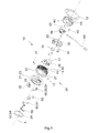
- FIG. 1 illustrated embodiment of the lighting device 10 comprises a housing 12 having a lateral surface 14 on which a thread 16 is located, on which an assembly nut 18 can be screwed.
- the housing 12 has a radially projecting collar 20, on which a about a longitudinal axis L of the lighting device 10 rotatable actuator 21 can be attached.
- the adjusting element 21 is designed as a cover 24 enclosing a collar 23.
- the adjusting ring 23 is fastened to the housing 12 by means of a bayonet connection.
- the adjusting ring 23 has a latching element 25 which cooperates with a projection 27 on the inner surface of the housing 12 and the adjusting ring 23 fixed axially.
- the projection 27 extends over a wide area along the inner surface, so that the adjusting ring 23 can be rotated in the attached state over a corresponding angular range, without the axial fixation is canceled.
- the cover 24 cooperates with the adjusting element 21, so that it can be rotated by turning the adjusting element 21 about the longitudinal axis L of the lighting device 10.
- the actuating element 21 can interact directly with the cover 24 or indirectly with the bearing unit 26.
- the cover 24 is rotated by the bearing unit 26 is rotated by the actuator 21.
- the bearing unit 26 comprises a support element 28 which is connected to the cover 24 and which can be introduced into a bearing ring 30 and can be fastened thereto.
- the support member 28 can be rotated in the bearing ring 30 both about the longitudinal axis L and about a perpendicular to the longitudinal axis L extending transverse axis Q.
- the bearing ring 30 further comprises a rack 32 which cooperates with a damping element 34 which is arranged in the support element 28.
- the support element 28 is biased relative to the bearing ring 30 by means of a spring element 36.
- a locking element 38 is provided, which cooperates with the support element 28 and the bearing ring 30.
- the rack 32 and the locking element 38 define a first, a second and a third position, between which the support member 28 and thus the cover 24 can be moved.
- the support element 28 and the bearing ring 30 are positioned and fixed in the housing 12 by means of a fixing element 40.
- the fixing element has one or more fixing hooks 41, which in openings or recesses 43 of the housing 12 intervene.
- one or more stop elements 42 are further provided, with which the mobility of the lid 24 can be limited to the longitudinal axis L. Limiting the mobility of the lid 42 is further important because it prevents the lid 42 from being rotated to a position in which the bayonet connection to the housing 12 can be released.
- the bearing ring 30 includes a latching cam 22 which cooperates with the fixing element 40.
- spring-biased pins 45 are provided, which can be introduced into corresponding holes of the fixing element 40.
- the support element 28 has a bearing surface 44 with an opening or a recess 46.
- a light source 48 is arranged, which comprises a lens 52 and an LED 50 and a first circuit board 54.
- the lens 52 covers the opening or the recess 46.
- a second circuit board 56 is arranged, which is connected via a cable harness 58 with the first circuit board 54. From the second circuit board 56 performs a line 60 from the power supply, which is also referred to as pigtail 60. With the pigtail 60, the lighting device 10 can be connected to a power supply network, for example, of the aircraft.
- the lens 52 focuses the light generated by the LED 50 so that a beam axis S is present. This is according to the invention in the first position of the lid 24 with respect to a plane perpendicular to the longitudinal axis L level by an angle ⁇ inclined to the second position. This can be done either by a correspondingly aligned installation of the LED 50 or by the fact that the lens 52 used has a corresponding curvature.
- the lid 24 has an end face 68 with one or more transparent regions 62. These can be produced, for example, by producing the lid 24 from a transparent material and, with the exception of the transparent areas 62, coating it with an intransparent lacquer.
- the transparent regions 62 are illuminated by means of a light guide 66 and a further light source 67.
- the transparent region 62 is arranged in a depression 64 of the end face 68, which gives the user an indication of where the cover 24 is preferably to be actuated.
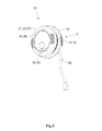
- FIG. 2 the lighting device 10 according to the invention is shown in the assembled state in the first position.
- the adjusting element 21 has a surface 70 which extends without outward edges adjacent to the end face 68.
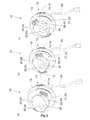
- the locking element 38 is unlocked, so that the support element 28 is placed under the action of the spring element 36 applied biasing force in the second position, in FIG. 3 is shown.
- the light source 48 is turned on.
- the opening 46 is no longer covered by the actuator 21 or by the storage unit 26 in the second position. Consequently, a cone of light can leave the lighting device 10 and illuminate an object.
- the light cone can be rotated about the longitudinal axis L of the lighting device 10.
- FIG. 3a is the actuator 21 and thus the cover 24 by about 30 ° to the left and in Figure 3c ) turned by approx. 30 ° to the right, starting from the in FIG. 3b ) center position.
- FIG. 4 shows in principle how the light source 48 and the support member 28 are moved with the lid 24 between the first and the second position.
- the first position is marked with the index 1 and the second position with the index 2.
- the lid 24 is shown greatly simplified as a line which extends along the maximum extent of the lid. Since the light source 48 is attached to the support element 28, it is located on the line which symbolizes the cover 24 and the support element 28.
- the longitudinal axis L and the transverse axis Q define a plane E, wherein the plane E perpendicular to the longitudinal axis L and the transverse axis Q in the plane E extend. It is assumed that the cover 24 extends in the first position along the transverse axis Q.
- the beam axis S of the light source 48 which is arranged on the bearing surface 44 of the support element 28, does not run parallel to the transverse axis Q, but forms an angle ⁇ with it. If the support member 28 is brought to the lid 24 in the second position, the angle ⁇ moves with. In this way it is achieved that the beam axis S with respect to the plane E in the second position forms an angle which is greater by ⁇ than the angle by which the support element and the cover have been pivoted between the first and the second position ,
Abstract
Description
- Die vorliegende Erfindung betrifft eine Beleuchtungsvorrichtung, insbesondere eine Leseleuchte. Derartige Beleuchtungsvorrichtungen werden als Leseleuchte insbesondere dort eingesetzt, wo sich die Lichtverhältnisse zeitlich häufig ändern und die Ausleuchtung eines bestimmten Sektors individuell anpassbar sein soll. Typische Anwendungsbereiche sind Flugzeuge und Züge, bei denen sich die Lichtverhältnisse beispielsweise beim Durchfliegen von Wolken oder Durchfahren von Tunneln ändern, wobei eine großräumige Ausleuchtung der Kabine oder des Abteils jedoch einerseits zu energieintensiv und andererseits nicht individuell anpassbar ist. Die individuelle Anpassbarkeit soll dabei die Möglichkeit schaffen, die Ausleuchtung eines bestimmten Sektors oder Objekts, die sich vorzugsweise innerhalb des Sitzplatzbereichs eines Passagiers befinden, auf die Wünsche des Passagiers anzupassen. Will der Passagier lesen, so soll ihm eine ausreichende Ausleuchtung des Informationsträgers zur Verfügung gestellt werden. Will er nicht lesen und beispielsweise eine Ruhepause einlegen, soll die Ausleuchtung ausschaltbar sein. Gleichzeitig soll die Ausleuchtung so gestaltet sein, dass der Nachbar nicht gestört wird.
- Aus der
DE 19926561 A1 ist eine Beleuchtungsvorrichtung, insbesondere eine Leseleuchte, mit einer Lichtquelle, einem die Lichtquelle tragenden Rahmen, welcher um mindestens eine horizontale und/oder eine vertikale Achse drehbar bzw. schwenkbar und in der ausgewählten Stellung feststellbar ausgeführt ist, bekannt. - Andere Formen der gattungsgemäßen Beleuchtungsvorrichtung sind beispielsweise aus der
DE 19741038 A1 oder derUS 2,011,692 A bekannt, bei der die Lichtquelle jeweils an einem drehbaren Bauteil, wie einem um seine Längsachse in einem Gehäuse drehbar gelangerten Schwenkzylinder, oder in einer schwenkbaren Klappe angeordnet ist. - Die
WO 2006/041417 offenbart eine Leseleuchte, die sich auf der Unterseite eines Monitors befindet, der aus der Rücklehne eines Flugzeugsitzes heraus schwenkbar ist. Mit dieser Leseleuchte kann der Klapptisch beleuchtet werden. Allerdings ist diese Leseleuchte an den Monitor gebunden, so dass sie nur in bestimmten Positionen eingesetzt werden kann. Weiterhin muss der Monitor aus der Rücklehne heraus geschwenkt werden, damit die Leseleuchte aktiviert wird. Der Monitor deckt somit beispielsweise einen Teil des Informationsträgers ab und engt den ohnehin schon knappen Raum für den Passagier weiter ein. - Insbesondere bei der Verwendung einer derartigen Leseleuchte in Flugzeugen sind weitere besondere Anforderungen zu berücksichtigen. Der zur Verfügung stehende Bauraum ist in Flugzeugkabinen sehr begrenzt, weiterhin soll das Gewicht der Beleuchtungsvorrichtung so weit wie möglich reduziert werden. Zudem darf die Beleuchtungsvorrichtung kein Verletzungsrisiko darstellen und muss strengen Brandschutzanforderungen genügen und soll insbesondere schwer entflammbar sein.
- Die
WO 2008/055694 offenbart eine Beleuchtungsvorrichtung, die einerseits kompakt aufgebaut ist und andererseits eine flexible Ausleuchtung von Objekten gewährleistet, mit einer Lichtquelle und einem um einen Schwenk-Kipp-Punkt verschwenkbares und/oder verkippbares Lichtleitelement, das zumindest eine Lichtleitachse und zumindest eine Lichteinkoppelfläche sowie eine Lichtauskoppelfläche aufweist, wobei das Lichtleitelementaxial verschiebbar und so angeordnet ist, dass zwischen der Lichtquelle und der Lichteinkoppelfläche ein Freistrahlbereich bestehen kann. Diese Vorrichtung hat sich in der Praxis bewährt, jedoch stellt sie hohe Anforderungen an die Fertigungsgenauigkeit und benötigt eine relativ aufwendige Mechanik. - Aufgabe der vorliegenden Erfindung ist es daher, eine Beleuchtungsvorrichtung anzugeben, die den oben genannten Anforderungen entspricht, zuverlässig ist und gleichzeitig den Nachteilen der aus dem Stand der Technik bekannten Beleuchtungsvorrichtungen begegnet. Weiterhin soll die Beleuchtungsvorrichtung dem Benutzer ein hohes Maß an Bedienungskomfort bieten und eine ansprechende Optik und Haptik aufweisen.
- Gelöst wird die Aufgabe mit einer Beleuchtungsvorrichtung, insbesondere mit einer Leseleuchte, umfassend eine Lichtquelle, einen bewegbaren Deckel, an welchem die Lichtquelle befestigbar ist, ein mit dem Deckel zusammenwirkendes Stellelement und eine Lagerungseinheit zum Lagern des Deckels und des Stellelements, wobei der Deckel und die Lichtquelle durch Betätigen des Stellelements um die Längsachse der Beleuchtungsvorrichtung und durch Betätigen des Deckels um eine senkrecht zur Längsachse verlaufende Querachse bewegbar sind. Das Stellelement ist für den Benutzer gut zugänglich, so dass der Deckel und die mit dem Deckel verbundene Lichtquelle mittels des Stellelements um die Längsachse bewegt und insbesondere um die Längsachse gedreht werden kann. Der von der Lichtquelle generierte Lichtkegel kann damit auf eine für den Benutzer bequeme Weise verstellt werden. Die erfindungsgemäße Gestaltung der Beleuchtungsvorrichtung ermöglicht es, die Anzahl der benötigten Bauteile zu reduzieren, wodurch ein kompakterer Aufbau der Beleuchtungsvorrichtung ermöglicht wird. Weiterhin führt die Reduzierung der Anzahl der Bauteile zu einer Erhöhung der Zuverlässigkeit der Beleuchtungsvorrichtung.
- Bevorzugt ist das Stellelement als ein den Deckel ringförmig umschließender Stellring ausgestaltet, wobei die Lichtquelle durch Betätigen des Deckels von einer ersten Stellung in eine zweite Stellung um die Querachse schwenkbar ist und die Lichtquelle in der ersten Stellung vom Stellring oder von der Lagerungseinheit verdeckt ist. Dadurch, dass die Lichtquelle vom Stellring in der ersten Stellung verdeckt wird, erzeugt sie keinen die Beleuchtungsvorrichtung verlassenden Lichtkegel. Für den Benutzer erscheint sie somit als ausgeschaltet, auch wenn sie dennoch eingeschaltet ist. In dieser Ausführung kann.auf eine Schaltvorrichtung zum ein- und Ausschalten der Lichtquelle verzichtet werden, was einen kompakten Aufbau der Beleuchtungsvorrichtung ermöglicht. Die Lichtquelle kann dabei ständig eingeschaltet sein. Die Ausgestaltung des Stellelements als Stellring, der den Deckel umschließt, bietet dem Benutzer eine komfortable Möglichkeit, den Deckel zu drehen.
- Eine bevorzugte Ausgestaltung der erfindungsgemäßen Beleuchtungsvorrichtung zeichnet sich dadurch aus, dass die Lichtquelle durch Betätigen des Deckels ein- und ausschaltbar ist, wobei sich die Lichtquelle in der ersten Stellung im ausgeschalteten Zustand und in der zweiten Stellung im eingeschalteten Zustand befindet. In dieser Ausgestaltung übernimmt der Deckel weiterhin eine Schaltfunktion, so dass auf ein weiteres Schalt- oder Betätigungselement verzichtet werden kann. Wie oben ausgeführt, wird durch Betätigen des Deckels der Deckel selbst und die mit ihm zusammenwirkende Lichtquelle um die Querachse der Beleuchtungsvorrichtung bewegt. Gleichzeitig ist durch Betätigen des Deckels die Lichtquelle ein- und ausschaltbar, so dass der Benutzer bestimmen kann, in welche Position er die Lichtquelle stellen und sie ein- oder ausschalten will. In der ersten Stellung ist die Lichtquelle vom Stellelement verdeckt, so dass sie keinen die Vorrichtung verlassenden Lichtkegel erzeugt. Somit trägt die Beleuchtungsvorrichtung in der ersten Stellung nicht zur Ausleuchtung eines bestimmten Sektors oder eines Objekts außerhalb der Beleuchtungsvorrichtung bei. In dieser Ausgestaltung wird die Lichtquelle in der ersten Stellung ausgeschaltet, so dass keine unnötige Energie verbraucht und keine unnötige Wärme innerhalb der Beleuchtungsvorrichtung erzeugt wird. Die Beleuchtungsvorrichtung kann somit energetisch günstiger und materialschonender und damit länger betrieben werden. Weiterhin dient der Deckel gleichzeitig als eine Art Tastwippe, mit der die Lichtquelle ein- und ausgeschaltet werden kann. Dies kann beispielsweise durch einen entsprechend gestalteten Kontaktschalter realisiert sein.
- In einer Fortbildung der erfindungsgemäßen Beleuchtungsvorrichtung weist die Lichtquelle eine Strahlachse auf, die in der ersten Stellung gegenüber einer senkrecht zur Längsachse verlaufenden Ebene um einen Winkel zur zweiten Stellung hin geneigt ist. Der Deckel und die Lichtquelle können üblicherweise konstruktionsbedingt nicht in beliebigem Umfang um die Querachse bewegt werden. Ein bestimmter Verstellbereich kann typischerweise nicht überschritten werden. Es kann jedoch der Fall eintreten, dass ein Objekt beleuchtet werden soll, das mit dem zur Verfügung stehenden Verstellbereich nicht erreichbar ist, wenn die Strahlachse in der ersten Stellung der Lichtquelle senkrecht zur Längsachse verläuft. Die Neigung der Strahlachse der Lichtquelle in der ersten Stellung gegenüber der senkrecht zur Längsachse verlaufenden Ebene hin zur zweiten Stellung sorgt dafür, dass auch dieses Objekt beleuchtet werden kann. Vorzugsweise beträgt der Winkel zwischen 1 und 20°, typischerweise 8 bis 10°. Der Winkel wird entsprechend der Anordnung der zu beleuchtenden Objekte gewählt. Es kann eine Verstellvorrichtung vorgesehen sein, mittels derer sich der Winkel verstellen lässt, so dass der von der Lichtquelle erzeugte Lichtkegel auf einfache Weise an die Gegebenheiten der auszuleuchtenden Umgebung angepasst werden kann.
- Weiterhin umfasst die Lagerungseinheit in einer weiteren Ausgestaltung einen Lagerring und ein darin einbringbares und bewegbares Tragelement, wobei das Tragelement mit dem Deckel verbindbar ist. Mit dieser Anordnung kann auf einfache Weise die benötigte Bewegbarkeit des Deckels bereitgestellt und gleichzeitig eine einfache Montage realisiert werden.
- Es ist weiterhin bevorzugt, wenn der Deckel eine Stirnfläche und das Stellelement eine an die Stirnfläche angrenzende Oberfläche aufweisen, wobei die Stirnfläche und die Oberfläche in der ersten Stellung kantenfrei zueinander verlaufen. Dies hat zum einen optische Vorteile, da die Beleuchtungsvorrichtung als eine homogene Einheit wirkt, und zum anderen wird dadurch erreicht, dass keine Kanten erzeugt werden, die ein Verletzungsrisiko darstellen können. Dabei müssen die Stirnfläche des Deckels und die sich der Stirnfläche anschließende Oberfläche des Stellelements nicht notwendigerweise planar sein, sondern können jeweils eine Wölbung aufweisen, die nicht stetig ineinander übergehen müssen. Ebenfalls ist es denkbar, dass die Stirnfläche planar ist, die sich der Stirnfläche anschließende Oberfläche des Stellelements jedoch gewölbt ist. Die Stirnfläche des Deckels kann dabei durchaus über die Oberfläche des Stellelements vorstehen oder aber im Stellelement versenkt sein.
- Vorzugsweise umfasst die Lagerungseinheit ein Gehäuse, an dem das Stellelement bzw. der Stellring drehbar befestigbar ist. Das Stellelement bzw. der Stellring können mittels einer Bajonettverbindung am Gehäuse befestigt werden. Das Gehäuse schützt und stabilisiert die Beleuchtungsvorrichtung. Weiterhin dient das Gehäuse als Aufnahme des Stellelements, so dass hierzu keine weiteren Bauteile benötigt werden. Zur Aufnahme des Stellelements kann das Gehäuse an einem Ende einen radial überstehenden Kragen aufweisen.
- In einer Fortbildung der erfindungsgemäßen Beleuchtungsvorrichtung umfasst die Lagerungseinheit eine Rastkurve, die beim Drehen des Stellrings durchlaufen wird. Die Rastkurve kann beispielsweise an der Oberfläche des Gehäuses angeordnet sein, die mit dem Stellelement zusammenwirkt. Die Rastkurve kann dabei eine Anzahl von Vorsprüngen aufweisen, die von einem elastischen Teil beim Drehen des Stellelements überwunden werden müssen. Die elastischen Teile können beispielsweise federbelastete Pins sein. Befindet sich das elastische Element in einer Vertiefung zwischen zwei benachbarten Vorsprüngen, wird eine Stellposition des Stellelements festgelegt. Je nach Anzahl der Vorsprünge werden mehr oder weniger Stellpositionen erzeugt. Einerseits wird verhindert, dass sich das Stellelement selbständig verstellt, andererseits erhält der Benutzer eine haptische Rückmeldung, die ihm eine gewisse Führung beim Drehen des Stellelements gibt.
- Vorzugsweise weist das Gehäuse eine Mantelfläche mit einem Gewinde auf, auf welches eine oder mehrere Montagemuttern aufschraubbar sind. Das Gehäuse kann in eine Einbauöffnung beispielsweise einer Trennwand oder eines Flugzeugsitzes eingesetzt und mittels der Montagemuttern an den die Einbauöffnung umgebenden Oberflächen befestigt werden. Weist das Gehäuse den radial überstehenden Kragen auf, auf den das Stellelement aufgesetzt wird, dient der Kragen zusätzlich als Auflagefläche, mit welcher die Beleuchtungsvorrichtung auf die die Einbauöffnung umgebenden Oberflächen aufgesetzt und mittels der Montagemutter über die auf der gegenüberliegenden Seite der Wandung liegenden Oberflächen verspannt werden kann. In diesem Fall wird nur eine Montagemutter benötigt. Weist das Gehäuse den radial überstehenden Kragen nicht auf, kann die Beleuchtungsvorrichtung mit zwei Montagemuttern verspannt werden. Je weiter sich die Montagemuttern und der radial überstehende Kragen radial über das Gehäuse erstrecken, desto größer kann auch die Einbauöffnung sein, in welche die Befestigungsvorrichtung einsetzbar ist. Hierdurch wird eine erhöhte Flexibilität bei der Montage ermöglicht, da kein speziell auf die Beleuchtungsvorrichtung angepasster Bohrungsdurchmesser für die Einbauöffnung vorgesehen werden muss. Eine besondere Toleranz oder Genauigkeit muss ebenfalls nicht eingehalten werden. Weiterhin kann die Beleuchtungsvorrichtung in Wandungen mit unterschiedlicher Wandstärke eingebaut werden.
- Weiterhin ist es vorteilhaft, wenn das Tragelement eine Lagerfläche mit einer Ausnehmung oder einem Durchbruch aufweist und der von der Lichtquelle erzeugte Lichtkegel die Ausnehmung oder den Durchbruch durchscheint oder die Lichtquelle in der Ausnehmung oder im Durchbruch angeordnet ist. Die Lagerfläche bewirkt, dass das Tragelement im Lagerring beweglich ist und vom Lagerring gehalten wird. Je nach Ausgestaltung bewirkt der Durchbruch der die Ausnehmung, dass die Lichtquelle im Tragelement und damit raumsparend angeordnet werden kann. Das Tragelement dient daher nicht nur der Lagerung des Deckels, sondern auch der Befestigung der Lichtquelle.
- Vorzugsweise ist der Deckel durch Verstellen von der zweiten in eine dritte Stellung mittels eines Verriegelungselements verriegelbar und vorspannbar und wird infolge der Vorspannkraft in die erste Stellung bewegt, und ist durch Verstellen von der ersten in die dritte Stellung entriegelbar und wird infolge der Vorspannkraft in die zweite Stellung bewegt. Hierdurch wird für den Benutzer eine besonders einfache Bedienbarkeit bereitgestellt. Zum Bewegen des Deckels und damit zum Einschalten der Lichtquelle muss der Benutzer den Deckel nur in eine dritte Stellung stellen, was vorzugsweise durch Drücken des Deckels in der ersten Stellung geschieht. Die dritte Stellung liegt dabei auf der von der zweiten Stellung abgewandten Seite der senkrecht zur Längsachse verlaufenden Ebene. In der dritten Stellung wird das Verriegelungselement entriegelt und der Deckel infolge der Vorspannkraft in die zweite Stellung bewegt, sobald der Benutzer den Deckel freigibt. Zum Verriegeln des Deckels bewegt der Benutzer den Deckel gegen die Vorspannkraft in die dritte Stellung, in weicher das Verriegelungselement verriegelt wird. Der Deckel bewegt sich dann infolge der Vorspannkraft zurück in die erste verriegelte Stellung, in welcher er solange verbleibt, bis er vom Benutzer wieder auf die zuvor beschriebene Weise entriegelt wird.
- Bevorzugt ist der Deckel mittels eines Federelements vorspannbar. Federelemente sind weit verbreitete und damit kostengünstig beziehbare Bauteile, die sich durch eine hohe Zuverlässigkeit und ein geringes Gewicht auszeichnen. Weiterhin sind die Federelemente auch in räumlich beengten Umgebungen einsetzbar, so dass die Vorspannung des Deckels auf raum-, kosten- und gewichtssparende Weise realisierbar ist. Durch Bewegen des Deckels von der zweiten in die dritte Stellung wird das Federelement vorgespannt, so dass die Vorspannkraft erzeugt wird.
- In einer weiteren Ausgestaltung weisen das Tragelement eine Zahnstange und der Lagerring ein Dämpfungselement auf, die zum Bewegen des Deckels um die Querachse zusammenwirken und die Bewegbarkeit des Deckels um die Querachse begrenzen. Weiterhin bremsen sie die Bewegung des Deckels zwischen der ersten bzw. der dritten und der zweiten Stellung. Das Bewegen des Deckels zwischen der ersten bzw. der dritten und der zweiten Stellung geschieht damit auf eine sanfte Weise, so dass der Deckel nicht ruckartig von der ersten bzw. dritten Stellung in die zweite Stellung springt. Die Bauteile werden somit geschont, da ein hartes Anschlagen verhindert wird. Das Dämpfungselement weist dabei ein Zahnrad mit einer entsprechend gedämpften Lagerung auf, welches auf der Zahnstange abrollt. Die Zahnstange ist gebogen und folgt der Bewegung des Tragelements. Die Begrenzung der Bewegbarkeit kann dadurch erreicht werden, dass das Zahnrad oder die Zahnstange einen erhöhten Zahn aufweisen, der das Abrollen des Zahnrads auf der Zahnstange ab einer bestimmten Stellung unterbindet. Alternativ kann die Verzahnung beispielsweise der Zahnstange enden, so dass die Zähne des Zahnrads nicht mehr mit den korrespondierenden Zähnen der Zahnstange zusammenwirken können, wodurch ab einer bestimmten Stellung des Tragelements relativ zum Lagerring die Bewegbarkeit nicht mehr gegeben ist. Die aktive Begrenzung der Bewegbarkeit ist insbesondere deshalb wichtig, weil aus konstruktiven Gründen nur ein bestimmtes Maß der Bewegbarkeit zwischen der ersten und der zweiten Stellung realisierbar ist, welches nicht überschritten werden darf, da sonst das Tragelement aus dem Lagerring herausgelöst werden könnte.
- Weiterhin weist die Beleuchtungsvorrichtung ein mit dem Gehäuse zusammenwirkenden Fixierelement zum Fixieren des Lagerrings und des Tragelements auf. Auf diese Weise können der Lagerring und das Tragelement auf einfache Weise in ihrer Position fixiert werden, wozu das Fixierelement und das Gehäuse mittels einer Klips- oder Schnappverbindung verbunden werden können. Das Fixierelement schließt das Gehäuse auf der dem Deckel gegenüberliegenden Seite ab, so dass keine Feuchtigkeit in das Gehäuse eindringen kann. Dies ist insbesondere im Hinblick auf die im Innenraum des Gehäuses angeordneten elektronischen Teile wichtig.
- In einer bevorzugten Weiterentwicklung ist die Lichtquelle um 40° oder weniger um die Längsachse (L) und um 40° oder weniger um die Querachse (Q) drehoder schwenkbar ist, wobei die Bewegbarkeit der Lichtquelle um die Längsachse (L) mittels eines oder mehrerer Anschlagelemente (42) begrenzbar ist. Hierdurch kann beispielsweise verhindert werden, dass die Lichtquelle auf einen Gegenstand gerichtet wird, der sich auf dem Sitz des Nachbarn befindet. Störungen des Nachbarn werden somit verhindert. Weiterhin wird verhindert, dass die Lichtquelle mehrmals in derselben Drehrichtung um die Längsachse gedreht wird, was zu einer Verdrehung und gegebenenfalls zu einer Beschädigung der Kabel oder zum Bruch von Lötverbindungen führen kann. Ein weiterer technischer Effekt ergibt sich daraus, dass der Stellring, der mittels einer Bajonettverbindung am Gehäuse befestigt ist, nicht in eine Stellung gedreht werden kann, in welcher die Bajonettverbindung getrennt und der Stellring vom Gehäuse entfernt werden kann.
- Vorzugsweise ist die Lichtquelle um 80° oder weniger um die Längsachse und um 40° oder weniger um die Querachse dreh- oder schwenkbar, wobei die Bewegbarkeit der Lichtquelle um die Längsachse mittels eines oder mehrerer Anschlagelemente begrenzbar ist. Es hat sich herausgestellt, dass eine Drehund Schwenkbarkeit innerhalb dieses Winkelbereichs für den erfindungsgemäßen Gebrauch ausreicht und gleichzeitig konstruktiv gut beherrschbar ist, ohne dass gesonderte Maßnahmen ergriffen werden müssen, die weiteren Bauraum benötigen. Der Aufbau der Beleuchtungsvorrichtung kann somit konstruktiv einfach und kompakt ausgeführt werden. Die Anschlagelemente können vorzugsweise in Winkelschritten von 5° verstellt werden, so dass innerhalb des angegebenen Winkelbereichs bevorzugte Zwischenstellungen eingestellt werden können. Hierdurch können Besonderheiten der auszuleuchtenden Umgebung berücksichtigt werden.
- Vorzugsweise umfasst die Lichtquelle eine LED mit einer Linse zum Fokussieren des Strahlengangs. LEDs zeichnen sich durch eine hohe Energieausnutzung bei geringer Wärmeentwicklung und geringem Platzbedarf aus. Weiterhin kann mit der Linse der gewünschte Lichtkegel erzeugt werden, mit dem beispielsweise die Informationsträger oder der Klapptisch im Flugzeug beleuchtet werden kann. In einer Weiterentwicklung ist die LED auf einer ersten Schaltplatine montiert, die im Deckel angeordnet ist. Die erste Schaltplatine umfasst einen Mikroschalter, der beim Verstellen des Deckels von der ersten in die zweite Stellung dafür sorgt, dass die LED eingeschaltet und beim Verstellen von der zweiten in die erste Stellung ausgeschaltet wird. Diese Anordnung ermöglicht einen kompakten Aufbau der Beleuchtungsvorrichtung. Dabei ist die erste Schaltplatine über einen Kabelbaum mit einer zweiten Schaltplatine verbindbar, welche die Spannungsversorgung und die Kontrolleinrichtung für die LED aufweist. Das Vorsehen von zwei Schaltplatinen schafft eine Platzersparnis im Deckel.
- Weiterhin ist es bevorzugt, wenn der Deckel einen oder mehrere transparente Bereiche aufweist, die mit mindestens einer weiteren Lichtquelle beleuchtbar sind. Dabei kann es hilfreich sein, mindestens einen Lichtleiter hinter dem transparenten Bereich im Deckel vorzusehen, um den transparenten Bereich homogen auszuleuchten. Die transparenten Bereiche dienen als Orientierungshilfe im Dunkeln, um die Position der Beleuchtungsvorrichtung und insbesondere des Deckels ermitteln zu können. Der transparente Bereich ist unabhängig von der Lichtquelle beleuchtbar und kann immer oder nur dann, wenn die Lichtquelle ausgeschaltet ist, oder in Abhängigkeit der Lichtverhältnisse der Umgebung beleuchtet sein. Dabei kann die weitere Lichtquelle ebenfalls als LED ausgeführt sein, die auf der ersten Schaltplatine angeordnet ist. Um Platz einzusparen, kann die weitere Lichtquelle so klein wie möglich ausgeführt werden. Der Lichtleiter dient dazu, den transparenten Bereich homogen auszuleuchten.
- Vorzugsweise bestehen der Deckel aus einem Polykarbonat und das Stellelement aus einem Acrylnitril-Butadien-Styrol (ABS) oder sie umfassen Polykarbonat und/oder Acrylnitril-Butadien-Styrol. Polykarbonate und PC/ABS-Blends oder Polyamid, welche glasfaserverstärkt sein können, sind besonders geeignet, um optisch und haptisch ansprechende Oberflächen kostengünstig herzustellen. Neben der erhöhten Festigkeit hat die Glasfaserverstärkung weiterhin den Vorteil, dass sie brandhemmend wirkt, so dass die Brandschutzanforderungen insbesondere der Luftfahrt erfüllt werden können. Diese Oberflächen können weiterhin mit üblicherweise verwendeten Reinigungsmitteln gesäubert werden und verfärben sich nicht bei der Einwirkung von Rotwein oder anderen Getränken. Zudem sind diese Oberflächen abriebfest, auch dann, wenn sie lackiert sind. Der Deckel und das Stellelement können im Spritzgussverfahren ohne sichtbare Entformungs-Trennlinien hergestellt werden. Hinsichtlich einer hohen Gestaltungsvielfalt können der Deckel und das Stellelement unterschiedlich lackiert sein. Besonders geeignet sind daher Lacksysteme, welche aus Haftvermittlern, Basislacken und einem klaren Decklack bestehen, wobei je nach verwendetem Kunststoff der Haftvermittler auch weggelassen werden kann. Alternativ können der Deckel und/oder das Stellelement verchromt oder beispielsweise mittels eines "plasma induced chemical vapor deposition" Verfahrens (PICVD) beschichtet sein. Die Dicke der Lack- oder Chromschicht beträgt in etwa zwischen 20 und 40 µm.
- Ein weiterer Aspekt der vorliegenden Erfindung betrifft die Verwendung einer Beleuchtungsvorrichtung nach einem der vorherigen Ausführungsbeispiele insbesondere als Leseleuchte in Flugzeugen, Schiffen, Zügen, Automobilen oder anderen Fahrzeugen. Die sich hieraus ergebenden Vorteile entsprechen denjenigen, die für die verschiedenen Ausführungsbeispiele der Beleuchtungsvorrichtung diskutiert worden sind.
- Die Erfindung wird unter Bezugnahme auf die anhängenden Zeichnungen anhand eines bevorzugten Ausführungsbeispiels im Detail erläutert. Es zeigen
- Figur 1
- eine Explosionszeichnung eines Ausführungsbeispiels der erfin-dungsgemäßen Beleuchtungsvorrichtung,
- Figur 2
- das in
Figur 1 dargestellte Ausführungsbeispiel der erfindungsge-mäßen Beleuchtungsvorrichtung im zusammengebauten Zustand in der ersten Stellung, - Figur 3
- das in den
Figuren 1 und2 dargestellte Ausführungsbeispiel in der zweiten Stellung, und - Figur 4
- eine prinzipielle Darstellung der Anordnung des Deckels und der Lichtquelle und der Strahlenachse relativ zur Längsachse der Be-leuchtungsvorrichtung.
- Das in
Figur 1 dargestellte Ausführungsbeispiel der erfindungsgemäßen Beleuchtungsvorrichtung 10 umfasst ein Gehäuse 12 mit einer Mantelfläche 14, auf dem sich ein Gewinde 16 befindet, auf das eine Montagemutter 18 aufgeschraubt werden kann. Das Gehäuse 12 weist einen radial überstehenden Kragen 20 auf, auf dem ein um eine Längsachse L der Beleuchtungsvorrichtung 10 drehbares Stellelement 21 befestigt werden kann. Im dargestellten Beispiel ist das Stellelement 21 als ein einen Deckel 24 umschließender Stellring 23 ausgebildet. Der Stellring 23 wird mittels einer Bajonettverbindung am Gehäuse 12 befestigt. Hierzu weist der Stellring 23 ein Rastelement 25 auf, welches mit einem Vorsprung 27 auf der Innenfläche des Gehäuses 12 zusammenwirkt und den Stellring 23 axial fixiert. Der Vorsprung 27 erstreckt sich über einen weiten Bereich entlang der Innenfläche, so dass der Stellring 23 im befestigten Zustand über einen entsprechenden Winkelbereich gedreht werden kann, ohne dass die axiale Fixierung aufgehoben wird. - Weiterhin weist die Beleuchtungsvorrichtung 10 den Deckel 24 auf, welcher mittels einer Lagerungseinheit 26 dreh- und schwenkbar gelagert ist. Der Deckel 24 wirkt mit dem Stellelement 21 zusammen, so dass er durch Drehen des Stellelements 21 um die Längsachse L der Beleuchtungsvorrichtung 10 gedreht werden kann. Dabei kann das Stellelement 21 direkt mit dem Deckel 24 oder indirekt mit der Lagerungseinheit 26 zusammenwirken. Im letzen Fall wird der Deckel 24 dadurch gedreht, dass die Lagerungseinheit 26 vom Stellelement 21 gedreht wird. Die Lagerungseinheit 26 umfasst dabei ein mit dem Deckel 24 verbundenes Tragelement 28, das in einen Lagerring 30 einbringbar und an diesem befestigbar ist. Das Tragelement 28 kann dabei im Lagerring 30 sowohl um die Längsachse L als auch um eine senkrecht zur Längsachse L verlaufende Querachse Q gedreht werden.
- Der Lagerring 30 weist weiterhin eine Zahnstange 32 auf, die mit einem Dämpfungselement 34 zusammenwirkt, das im Tragelement 28 angeordnet ist. Das Tragelement 28 wird gegenüber dem Lagerring 30 mittels eines Federelements 36 vorgespannt. Um das Tragelement 28 in der ersten Stellung zu verriegeln, ist ein Verriegelungselement 38 vorgesehen, das mit dem Tragelement 28 und dem Lagerring 30 zusammenwirkt. Die Zahnstange 32 und das das Verriegelungselement 38 legen eine erste, eine zweite und eine dritte Stellung fest, zwischen denen das Tragelement 28 und damit der Deckel 24 bewegt werden können.
- Das Tragelement 28 und der Lagerring 30 werden mittels eines Fixierelements 40 im Gehäuse 12 positioniert und befestigt. Das Fixierelement weist einen oder mehrere Fixierhaken 41 auf, die in Öffnungen oder Vertiefungen 43 des Gehäuses 12 eingreifen. Im Fixierelement 40 sind weiterhin ein oder mehrere Anschlagelemente 42 vorgesehen, mit denen die Bewegbarkeit des Deckels 24 um die Längsachse L begrenzt werden kann. Die Begrenzung der Bewegbarkeit des Deckels 42 ist weiterhin deshalb wichtig, da somit verhindert wird, dass der Deckel 42 in eine Position gedreht werden kann, in welcher die Bajonettverbindung zum Gehäuse 12 aufgelöst werden kann. Der Lagerring 30 umfasst eine Rastkurve 22, die mit dem Fixierelement 40 zusammenwirkt. Hierzu sind federvorgespannte Pins 45 vorgesehen, die in entsprechende Löcher des Fixierelements 40 eingebracht werden können. Deren freies Ende wirkt mit der Rastkurve 22 zusammen, gleichzeitig spannen die Pins 45 die tragenden Komponenten der Beleuchtungsvorrichtung 10 vor, so dass sie auch bei starken Vibrationen, wie sie insbesondere in Flugzeugkabinen vorkommen kann, nicht klappern. Beim Drehen des Stellelements 21 wird der Lagerring 30 ebenfalls gedreht und die Rastkurve 22 durchlaufen. Dabei muss abwechselnd eine stärkere oder eine geringere Kraft aufgewendet werden, die der Benutzer beim Drehen des Stellelements aufbringen muss und somit eine haptische Rückmeldung erhält.
- Das Tragelement 28 weist eine Lagerfläche 44 mit einem Durchbruch oder einer Ausnehmung 46 auf. Im Durchbruch oder in der Ausnehmung 46 und/oder radial einwärts hiervon ist eine Lichtquelle 48 angeordnet, die eine Linse 52 und eine LED 50 sowie eine erste Schaltplatine 54 umfasst. Die Linse 52 deckt dabei den Durchbruch oder die Ausnehmung 46 ab. Im Fixierelement 40 ist eine zweite Schaltplatine 56 angeordnet, die über einen Kabelbaum 58 mit der ersten Schaltplatine 54 verbunden ist. Von der zweiten Schaltplatine 56 führt eine Leitung 60 zur Energieversorgung ab, die auch als Pigtail 60 bezeichnet wird. Mit dem Pigtail 60 kann die Beleuchtungsvorrichtung 10 an ein Energieversorgungsnetz beispielsweise des Flugzeugs angeschlossen werden. Die Linse 52 fokussiert das von der LED 50 erzeugte Licht, so dass eine Strahlachse S vorliegt. Diese ist erfindungsgemäß in der ersten Stellung des Deckels 24 gegenüber einer senkrecht zur Längsachse L verlaufenden Ebene um einen Winkel α zur zweiten Stellung hin geneigt. Dies kann entweder durch einen entsprechend ausgerichteten Einbau der LED 50 oder dadurch geschehen, dass die verwendete Linse 52 eine entsprechende Wölbung aufweist.
- Der Deckel 24 weist eine Stirnfläche 68 mit einem oder mehreren transparenten Bereichen 62 auf. Diese können beispielsweise dadurch erzeugt werden, dass der Deckel 24 aus einem transparenten Material gefertigt und mit Ausnahme der transparenten Bereiche 62 mit einem intransparenten Lack beschichtet wird. Die transparenten Bereiche 62 werden mittels eines Lichtleiters 66 und einer weiteren Lichtquelle 67 beleuchtet. Der transparente Bereich 62 ist dabei in einer Mulde 64 der Stirnfläche 68 angeordnet, die dem Benutzer einen Anhaltspunkt gibt, wo der Deckel 24 vorzugsweise zu betätigen ist.
- In
Figur 2 ist die erfindungsgemäße Beleuchtungsvorrichtung 10 im zusammengebauten Zustand in der ersten Stellung gezeigt. Das Stellelement 21 weist eine Oberfläche 70 auf, die ohne nach außen stehende Kanten angrenzend zur Stirnfläche 68 verläuft. Durch Drücken des Deckels 24 in eine dritte Stellung wird das Verriegelungselement 38 entriegelt, so dass das Tragelement 28 unter Einwirkung der vom Federelement 36 aufgebrachten Vorspannkraft in die zweite Stellung gestellt wird, die inFigur 3 gezeigt ist. Gleichzeitig wird die Lichtquelle 48 eingeschaltet. Der Durchbruch 46 ist in der zweiten Stellung nicht mehr vom Stellelement 21 oder von der Lagerungseinheit 26 verdeckt. Folglich kann ein Lichtkegel die Beleuchtungsvorrichtung 10 verlassen und ein Objekt ausleuchten. Durch Drehen des Stellelements 21 kann der Lichtkegel um die Längsachse L der Beleuchtungsvorrichtung 10 gedreht werden. InFigur 3a ) ist das Stellelement 21 und damit der Deckel 24 um ca. 30° nach links und inFigur 3c ) um ca. 30° nach rechts gedreht, jeweils ausgehend von der inFigur 3b ) dargestellten Mittelposition. -
Figur 4 zeigt auf prinzipielle Weise, wie die Lichtquelle 48 und das Tragelement 28 mit dem Deckel 24 zwischen der ersten und der zweiten Stellung verstellt werden. Die erste Stellung ist dabei mit dem Index 1 und die zweite Stellung mit dem Index 2 gekennzeichnet. Der Deckel 24 ist stark vereinfacht als Linie dargestellt, welche entlang der maximalen Erstreckung des Deckels verläuft. Da die Lichtquelle 48 am Tragelement 28 befestigt ist, befindet sie sich auf der Linie, die den Deckel 24 und das Tragelement 28 symbolisiert. Die Längsachse L und die Querachse Q definieren eine Ebene E, wobei die Ebene E senkrecht zur Längsachse L und die Querachse Q in der Ebene E verlaufen. Es wird angenommen, dass der Deckel 24 in der ersten Stellung entlang der Querachse Q verläuft. Die Strahlenachse S der Lichtquelle 48, die an der Lagerfläche 44 des Tragelements 28 angeordnet ist, verläuft aber nicht parallel zur Querachse Q, sondern bildet mit ihr einen Winkel α. Wird das Tragelement 28 mit dem Deckel 24 in die zweite Stellung gebracht, wandert der Winkel □ mit. Auf diese Weise wird erreicht, dass die Strahlenachse S in Bezug auf die Ebene E in der zweiten Stellung einen Winkel bildet, der um α größer ist als der Winkel, um den das Tragelement und der Deckel zwischen der ersten und der zweiten Stellung geschwenkt worden sind. -
- 10
- Beleuchtungsvorrichtung
- 12
- Gehäuse
- 14
- Mantelfläche
- 16
- Gewinde
- 18
- Montagemutter
- 20
- radial überstehender Kragen
- 21
- Stellelement
- 22
- Rastkurve
- 23
- Stellring
- 24
- Deckel
- 25
- Rastelement
- 26
- Lagerungseinheit
- 27
- Vorsprung
- 28
- Tragelement
- 30
- Lagerring
- 32
- Zahnstange
- 34
- Dämpfungselement
- 36
- Federelement
- 38
- Verriegelungselement
- 40
- Fixierelement
- 41
- Fixierhaken
- 42
- Anschlagelement
- 43
- Öffnung, Vertiefung
- 44
- Lagerfläche
- 45
- vorgespannter Pin
- 46
- Durchbruch/Ausnehmung
- 48
- Lichtquelle
- 50
- LED
- 52
- Linse
- 54
- erste Schaltplatine
- 56
- zweite Schaltplatine
- 58
- Kabelbaum
- 60
- Leitung/Pigtail
- 62
- transparenter Bereich
- 64
- Mulde
- 66
- Lichtleiter
- 67
- Lichtquelle
- 68
- Stirnfläche
- 70
- Oberfläche
- E
- Ebene
- L
- Längsachse
- Q
- Querachse
- S
- Strahlachse
- α
- Winkel
Claims (16)
- Beleuchtungsvorrichtung, insbesondere Leselampe, mit- einer Lichtquelle (48),- einem bewegbaren Deckel (24), an welchem die Lichtquelle (48) befestigbar ist,- einem mit dem Deckel (24) zusammenwirkenden Stellelement (21), und- einer Lagerungseinheit (26) zum Lagern des Deckels (24) und des Stellelementes (21),
wobei der Deckel (24) und die Lichtquelle (48) durch Betätigen des Stellelements (21) um die Längsachse (L) der Beleuchtungsvorrichtung (10) und durch Betätigen des Deckels (24) um eine senkrecht zur Längsachse (L) verlaufende Querachse (Q) bewegbar sind. - Beleuchtungsvorrichtung nach Anspruch 1,
dadurch gekennzeichnet, dass das Stellelement (21) als ein den Deckel (24) ringförmig umschließender Stellring (23) ausgebildet ist und die Lichtquelle (48) durch Betätigen des Deckels (24) von einer ersten Stellung in eine zweite Stellung um die Querachse (Q) schwenkbar ist, wobei die Lichtquelle (48) in der ersten Stellung vom Stellring (23) und von der Lagerungseinheit (26) verdeckt ist. - Beleuchtungsvorrichtung nach Anspruch 1 oder 2,
dadurch gekennzeichnet, dass die Lichtquelle (48) durch Betätigen des Deckels (24) ein- und ausschaltbar ist, wobei sich die Lichtquelle (48) in der ersten Stellung im ausgeschalteten Zustand und in der zweiten Stellung im eingeschalteten Zustand befindet. - Beleuchtungsvorrichtung nach einem der vorherigen Ansprüche , dadurch gekennzeichnet, dass die Lichtquelle (48) eine Strahlachse (S) aufweist, die in der ersten Stellung gegenüber einer senkrecht zur Längsachse (L) verlaufenden Ebene (E) um einen Winkel (α) zur zweiten Stellung hin geneigt ist, der bevorzugt zwischen 1° und 20° beträgt.
- Beleuchtungsvorrichtung nach einem der vorherigen Ansprüche,
dadurch gekennzeichnet, dass die Lagerungseinheit (26) einen Lagerring (30) und ein darin einbringbares und bewegbares Tragelement (28) umfasst, wobei das Tragelement (28) mit dem Deckel (24) verbindbar ist. - Beleuchtungsvorrichtung nach einem der Ansprüche 2 bis 5,
dadurch gekennzeichnet, dass die Lagerungseinheit (26) ein Gehäuse (12) umfasst, an dem der Stellring (23) drehbar befestigbar ist. - Beleuchtungsvorrichtung nach Anspruch 6,
dadurch gekennzeichnet, dass die Lagerungseinheit (26) eine Rastkurve (22) umfasst, die beim Drehen des Stellrings (23) durchlaufen wird. - Beleuchtungsvorrichtung nach einem der vorherigen Ansprüche,
dadurch gekennzeichnet, dass das Tragelement (28) eine Lagerfläche (44) mit einer Ausnehmung oder einem Durchbruch (46) aufweist und der von der Lichtquelle (48) erzeugte Lichtkegel die Ausnehmung oder den Durchbruch (46) durchscheint oder die Lichtquelle (48) in der Ausnehmung oder im Durchbruch (46) angeordnet ist. - Beleuchtungsvorrichtung nach einem der vorherigen Ansprüche,
dadurch gekennzeichnet, dass der Deckel (24) durch Verstellen von der zweiten in eine dritte Stellung mittels eines Verriegelungselements (38) verriegelbar und vorspannbar ist und infolge der Vorspannkraft in die erste Stellung bewegt wird, und durch Verstellen von der ersten in die dritte Stellung entriegelbar ist und infolge der Vorspannkraft in die zweite Stellung bewegt wird. - Beleuchtungsvorrichtung nach Anspruch 9,
dadurch gekennzeichnet, dass der Deckel (24) mittels eines Federelements (36) vorspannbar ist. - Beleuchtungsvorrichtung nach Anspruch 7 bis 10,
dadurch gekennzeichnet, dass das Tragelement (28) eine Zahnstange (32) und der Lagerring (30) ein Dämpfungselement aufweisen, die zum Bewegen des Deckels (24) um die Querachse (Q) zusammenwirken und die Bewegbarkeit des Deckels (24) um die Querachse (Q) begrenzen. - Beleuchtungsvorrichtung nach Anspruch 7 bis 11,
gekennzeichnet durch ein mit dem Gehäuse (12) zusammenwirkenden Fixierelement (40) zum Fixieren des Lagerrings (30) und des Tragelements (28). - Beleuchtungsvorrichtung nach Anspruch 11 oder 12,
dadurch gekennzeichnet, dass die Lichtquelle (48) um 80° oder weniger um die Längsachse (L) und um 40° oder weniger um die Querachse (Q) dreh- oder schwenkbar ist, wobei die Bewegbarkeit der Lichtquelle um die Längsachse (L) mittels eines oder mehrerer Anschlagelemente (42) begrenzbar ist. - Beleuchtungsvorrichtung nach einem der vorherigen Ansprüche,
dadurch gekennzeichnet, dass die Lichtquelle (48) eine LED (50) mit einer Linse (52) zum Fokussieren des Strahlengangs (S) umfasst, wobei die LED (50) auf einer ersten Schaltplatine (54) montiert ist, die im Deckel (24) angeordnet und die erste Schaltplatine (54) über einen Kabelbaum (58) mit einer zweiten Schaltplatine (56) verbindbar ist. - Beleuchtungsvorrichtung nach Anspruch 14,
dadurch gekennzeichnet, dass der Deckel (24) einen oder mehrere transparente Bereiche (62) aufweist, die mittels mindestens einer weiteren Lichtquelle (67) beleuchtbar sind. - Verwendung einer Beleuchtungsvorrichtung (10) nach einem der vorherigen Ansprüche insbesondere als Leseleuchte in Flugzeugen, Schiffen, Zügen, Automobilen oder anderen Fahrzeugen.
Applications Claiming Priority (2)
| Application Number | Priority Date | Filing Date | Title |
|---|---|---|---|
| US39170710P | 2010-10-11 | 2010-10-11 | |
| DE201010042287 DE102010042287B9 (de) | 2010-10-11 | 2010-10-11 | Beleuchtungsvorrichtung, insbesondere Leseleuchte |
Publications (4)
| Publication Number | Publication Date |
|---|---|
| EP2439105A2 true EP2439105A2 (de) | 2012-04-11 |
| EP2439105A3 EP2439105A3 (de) | 2015-06-10 |
| EP2439105B1 EP2439105B1 (de) | 2016-08-17 |
| EP2439105B9 EP2439105B9 (de) | 2017-03-15 |
Family
ID=44651410
Family Applications (1)
| Application Number | Title | Priority Date | Filing Date |
|---|---|---|---|
| EP11181827.4A Active EP2439105B9 (de) | 2010-10-11 | 2011-09-19 | Beleuchtungsvorrichtung, insbesondere Leselampe |
Country Status (7)
| Country | Link |
|---|---|
| US (1) | US8602614B2 (de) |
| EP (1) | EP2439105B9 (de) |
| CN (1) | CN102563482B (de) |
| BR (1) | BRPI1106771A2 (de) |
| CA (1) | CA2754464A1 (de) |
| DE (1) | DE102010042287B9 (de) |
| ES (1) | ES2602047T3 (de) |
Cited By (5)
| Publication number | Priority date | Publication date | Assignee | Title |
|---|---|---|---|---|
| DE102013013106A1 (de) | 2013-08-06 | 2015-02-12 | Diehl Aerospace Gmbh | Beleuchtungsvorrichtung und Fahrzeug |
| EP2977265A1 (de) * | 2014-07-25 | 2016-01-27 | Audi Ag | Leuchtanordnung für ein kraftfahrzeug und kraftfahrzeug |
| EP3000658A1 (de) * | 2014-09-29 | 2016-03-30 | Airbus Operations GmbH | Leseleuchtenanordnung und Leseleuchtensystem für ein Fahrzeug |
| EP3064401A3 (de) * | 2015-03-04 | 2017-01-04 | Panasonic Avionics Corporation | Sitzlehnenbeleuchtungsmodul |
| DE102018108278A1 (de) | 2018-04-09 | 2019-10-10 | Schott Ag | Halbleiterbasierte Beleuchtungsvorrichtung |
Families Citing this family (16)
| Publication number | Priority date | Publication date | Assignee | Title |
|---|---|---|---|---|
| JP6210289B2 (ja) * | 2013-09-30 | 2017-10-11 | トヨタ紡織株式会社 | 車室内用照明装置 |
| DE102013018219B4 (de) * | 2013-10-29 | 2016-04-07 | Diehl Aerospace Gmbh | Leselampe zum Einbau in ein Kabinenverkleidungselement eines Fahrzeugs |
| CN103574471A (zh) * | 2013-10-31 | 2014-02-12 | 昆山市大久电子有限公司 | 万向汽车顶灯 |
| GB201506136D0 (en) * | 2015-04-10 | 2015-05-27 | Saf T Glo Ltd | Lighting unit |
| JP6706795B2 (ja) * | 2016-07-28 | 2020-06-10 | パナソニックIpマネジメント株式会社 | 照明システム及び移動体 |
| EP3542596A1 (de) * | 2016-11-18 | 2019-09-25 | Saf-t-Glo Limited | Nachgerüstete led-beleuchtungseinheit |
| CN107975720B (zh) * | 2017-12-21 | 2023-09-22 | 深圳市中联宇航科技有限公司 | 一种照明角度可调节的阅读灯 |
| DE102018101384A1 (de) * | 2018-01-23 | 2019-07-25 | Schott Ag | Halterung für eine Leuchte und Beleuchtungselement |
| JP2020050195A (ja) * | 2018-09-27 | 2020-04-02 | パナソニックIpマネジメント株式会社 | 移動体室内照明装置及び移動体 |
| DE102018220102A1 (de) * | 2018-11-22 | 2020-05-28 | Volkswagen Aktiengesellschaft | Leseleuchte im Innenraum eines Kraftfahrzeugs |
| USD937779S1 (en) * | 2019-08-05 | 2021-12-07 | eMoMo Technology Co., Ltd. | Reading lamp connector |
| CN110726093A (zh) | 2019-11-07 | 2020-01-24 | 深圳市一么么科技有限公司 | 一种阅读灯 |
| CN110783764A (zh) | 2019-11-07 | 2020-02-11 | 深圳市一么么科技有限公司 | 一种具有电源接口的设备支架基座 |
| CN110925657B (zh) * | 2019-12-02 | 2023-10-20 | 广东德洛斯照明工业有限公司 | 带有安装角度调节架的透镜灯 |
| CN113432057B (zh) * | 2020-03-06 | 2022-09-02 | 嘉兴海拉灯具有限公司 | 一种用于车辆的角度调节结构及一种阅读灯 |
| JP2022187921A (ja) | 2021-06-08 | 2022-12-20 | パナソニックIpマネジメント株式会社 | 照明装置 |
Citations (5)
| Publication number | Priority date | Publication date | Assignee | Title |
|---|---|---|---|---|
| US2011692A (en) | 1933-07-24 | 1935-08-20 | William E Simpson | Electric light |
| DE19741038A1 (de) | 1997-09-18 | 1999-03-25 | Hella Kg Hueck & Co | Leuchte für Fahrzeuge |
| DE19926561A1 (de) | 1999-06-11 | 2000-12-14 | Diehl Stiftung & Co | Strahler, insbesondere Leseleuchte in Kabinen von Fahrzeugen |
| WO2006041417A1 (en) | 2004-10-14 | 2006-04-20 | Singapore Airlines Limited | Aircraft passenger seat with a display monitor including a reading light |
| WO2008055694A1 (de) | 2006-11-09 | 2008-05-15 | Schott Ag | Beleuchtungsvorrichtung |
Family Cites Families (15)
| Publication number | Priority date | Publication date | Assignee | Title |
|---|---|---|---|---|
| US5070434A (en) * | 1990-10-09 | 1991-12-03 | Prince Corporation | Overhead light |
| US5951155A (en) * | 1997-09-03 | 1999-09-14 | Prince Corporation | Variable intensity light assembly |
| US7220029B2 (en) * | 2004-02-11 | 2007-05-22 | Federal-Mogul World Wide, Inc. | Lamp assembly having variable focus and directionality |
| US7261450B2 (en) * | 2004-05-27 | 2007-08-28 | International Automotive Components Group North America, Inc. | Dual function console lamp with integrated switching |
| US7249873B2 (en) * | 2004-09-07 | 2007-07-31 | Lear Corporation | Adjustable light beam device for aimable vehicle lamp assembly and method |
| US7311426B2 (en) * | 2005-03-10 | 2007-12-25 | International Automotive Components Group North America, Inc. | Adjustable beam lamp |
| US7434962B2 (en) * | 2006-06-19 | 2008-10-14 | Johnson Controls Technology Company | Low-profile, aimable lighting assembly |
| US7562995B1 (en) * | 2006-08-25 | 2009-07-21 | Jonathan Levine | Adjustable lighting device |
| US7744259B2 (en) * | 2006-09-30 | 2010-06-29 | Ruud Lighting, Inc. | Directionally-adjustable LED spotlight |
| CN200955712Y (zh) * | 2006-10-17 | 2007-10-03 | 张政煌 | 节能灯改良结构 |
| JP5332770B2 (ja) * | 2008-04-18 | 2013-11-06 | 東芝ライテック株式会社 | 照明器具 |
| US8267558B1 (en) * | 2008-10-03 | 2012-09-18 | B/E Aerospace, Inc. | Light rotation assembly |
| US20100091503A1 (en) * | 2008-10-14 | 2010-04-15 | Kuo Benny L | Lamp device |
| CN101852367B (zh) * | 2009-04-03 | 2014-07-16 | 鸿富锦精密工业(深圳)有限公司 | 照明装置 |
| US8132943B2 (en) * | 2010-08-04 | 2012-03-13 | Washington-Electronics Co. Ltd. | Adjustable recessed lighting fixture |
-
2010
- 2010-10-11 DE DE201010042287 patent/DE102010042287B9/de active Active
-
2011
- 2011-09-19 EP EP11181827.4A patent/EP2439105B9/de active Active
- 2011-09-19 ES ES11181827.4T patent/ES2602047T3/es active Active
- 2011-10-04 US US13/252,313 patent/US8602614B2/en active Active
- 2011-10-07 CA CA2754464A patent/CA2754464A1/en not_active Abandoned
- 2011-10-11 CN CN201110315344.8A patent/CN102563482B/zh not_active Expired - Fee Related
- 2011-10-11 BR BRPI1106771-3A2A patent/BRPI1106771A2/pt not_active Application Discontinuation
Patent Citations (5)
| Publication number | Priority date | Publication date | Assignee | Title |
|---|---|---|---|---|
| US2011692A (en) | 1933-07-24 | 1935-08-20 | William E Simpson | Electric light |
| DE19741038A1 (de) | 1997-09-18 | 1999-03-25 | Hella Kg Hueck & Co | Leuchte für Fahrzeuge |
| DE19926561A1 (de) | 1999-06-11 | 2000-12-14 | Diehl Stiftung & Co | Strahler, insbesondere Leseleuchte in Kabinen von Fahrzeugen |
| WO2006041417A1 (en) | 2004-10-14 | 2006-04-20 | Singapore Airlines Limited | Aircraft passenger seat with a display monitor including a reading light |
| WO2008055694A1 (de) | 2006-11-09 | 2008-05-15 | Schott Ag | Beleuchtungsvorrichtung |
Cited By (10)
| Publication number | Priority date | Publication date | Assignee | Title |
|---|---|---|---|---|
| DE102013013106A1 (de) | 2013-08-06 | 2015-02-12 | Diehl Aerospace Gmbh | Beleuchtungsvorrichtung und Fahrzeug |
| US9365156B2 (en) | 2013-08-06 | 2016-06-14 | Diehl Aerospace Gmbh | Lighting apparatus and vehicle |
| DE102013013106B4 (de) | 2013-08-06 | 2023-01-05 | Diehl Aerospace Gmbh | Beleuchtungsvorrichtung und Fahrzeug |
| EP2977265A1 (de) * | 2014-07-25 | 2016-01-27 | Audi Ag | Leuchtanordnung für ein kraftfahrzeug und kraftfahrzeug |
| EP3000658A1 (de) * | 2014-09-29 | 2016-03-30 | Airbus Operations GmbH | Leseleuchtenanordnung und Leseleuchtensystem für ein Fahrzeug |
| US10272834B2 (en) | 2014-09-29 | 2019-04-30 | Airbus Operations Gmbh | Reading light assembly and reading light system for a vehicle |
| EP3064401A3 (de) * | 2015-03-04 | 2017-01-04 | Panasonic Avionics Corporation | Sitzlehnenbeleuchtungsmodul |
| RU2713260C2 (ru) * | 2015-03-04 | 2020-02-04 | Панасоник Эйвионикс Корпорейшн | Осветительный модуль спинки сиденья |
| DE102018108278A1 (de) | 2018-04-09 | 2019-10-10 | Schott Ag | Halbleiterbasierte Beleuchtungsvorrichtung |
| US10813185B2 (en) | 2018-04-09 | 2020-10-20 | Schott Ag | Semiconductor-based lighting device |
Also Published As
| Publication number | Publication date |
|---|---|
| CN102563482A (zh) | 2012-07-11 |
| DE102010042287A1 (de) | 2012-04-12 |
| US20120087142A1 (en) | 2012-04-12 |
| US8602614B2 (en) | 2013-12-10 |
| CA2754464A1 (en) | 2012-04-11 |
| EP2439105B9 (de) | 2017-03-15 |
| DE102010042287B9 (de) | 2013-07-11 |
| EP2439105A3 (de) | 2015-06-10 |
| DE102010042287A9 (de) | 2012-06-14 |
| ES2602047T3 (es) | 2017-02-17 |
| EP2439105B1 (de) | 2016-08-17 |
| CN102563482B (zh) | 2014-11-12 |
| BRPI1106771A2 (pt) | 2013-07-16 |
| DE102010042287B4 (de) | 2012-08-02 |
Similar Documents
| Publication | Publication Date | Title |
|---|---|---|
| EP2439105B9 (de) | Beleuchtungsvorrichtung, insbesondere Leselampe | |
| DE102007048975A1 (de) | Schnellbefestigungseinrichtung | |
| DE202005012570U1 (de) | Luftdüse | |
| EP2454620A1 (de) | Lichtleiter, beleuchtungseinrichtung mit einem solchen lichtleiter und innenausstattungsteil für ein fahrzeug mit einer derartigen beleuchtungseinrichtung | |
| DE102007046999B3 (de) | Betätiger | |
| EP2885162B1 (de) | Halterung zur aufhebbaren arretierung eines laderaumbodens sowie fahrzeug mit der halterung | |
| DE19757085A1 (de) | Vorrichtung zur Beleuchtung eines Vorfeldes eines Fahrzeugteils | |
| EP1923266A1 (de) | Aussenrückblickspiegel für Fahrzeuge | |
| DE112012002628T5 (de) | Lenksäulenanordnung | |
| DE102008051155A1 (de) | Bildschirmverstelleinrichtung für ein Kraftfahrzeug | |
| DE102008051149A1 (de) | Bildschirmverstelleinrichtung für ein Kraftfahrzeug | |
| AT508605A1 (de) | Verstellvorrichtung zum verstellen eines optisch relevanten bauteiles eines fahrzeugscheinwerfers | |
| EP1854665A1 (de) | Scheinwerfer für Fahrzeuge und Montageverfahren | |
| DE102017005533A1 (de) | Drehwahlschalter | |
| DE2841419A1 (de) | Fernsteuervorrichtung | |
| DE102019220005A1 (de) | Drehsteller mit einer optischen Erfassung der Drehposition | |
| EP2463835A1 (de) | Infrarot-Bewegungssensor | |
| DE102018128362A1 (de) | Lenksäule für fahrzeuge | |
| DE102019203270B4 (de) | Bedieneinrichtung für ein Kraftfahrzeug, Kraftfahrzeug und Verfahren zum Bedienen einer Anzeigeeinrichtung | |
| EP3999415B1 (de) | Befestigungssystem zur befestigung eines bauteils, bauteilanordnung und luftfahrzeug | |
| EP2568103B1 (de) | Stufenloses Scharnier | |
| DE10202914A1 (de) | Ausfahrbarer Ladeboden für ein Fahrzeug | |
| DE102014107774A1 (de) | Beleuchtungseinrichtung für Kraftfahrzeuge | |
| DE102014226621B3 (de) | Drehbetätiger mit einer homogen ausgeleuchteten Anzeigefläche | |
| DE102013001128A1 (de) | Luftausströmer einer lüftungstechnischen Anlage sowie Fahrzeug mit zumindest einem derartigen Luftausströmer |
Legal Events
| Date | Code | Title | Description |
|---|---|---|---|
| 17P | Request for examination filed |
Effective date: 20110919 |
|
| AK | Designated contracting states |
Kind code of ref document: A2 Designated state(s): AL AT BE BG CH CY CZ DE DK EE ES FI FR GB GR HR HU IE IS IT LI LT LU LV MC MK MT NL NO PL PT RO RS SE SI SK SM TR |
|
| AX | Request for extension of the european patent |
Extension state: BA ME |
|
| PUAI | Public reference made under article 153(3) epc to a published international application that has entered the european phase |
Free format text: ORIGINAL CODE: 0009012 |
|
| PUAL | Search report despatched |
Free format text: ORIGINAL CODE: 0009013 |
|
| AK | Designated contracting states |
Kind code of ref document: A3 Designated state(s): AL AT BE BG CH CY CZ DE DK EE ES FI FR GB GR HR HU IE IS IT LI LT LU LV MC MK MT NL NO PL PT RO RS SE SI SK SM TR |
|
| AX | Request for extension of the european patent |
Extension state: BA ME |
|
| RIC1 | Information provided on ipc code assigned before grant |
Ipc: B60Q 3/02 20060101AFI20150504BHEP Ipc: B64D 11/00 20060101ALN20150504BHEP |
|
| RIC1 | Information provided on ipc code assigned before grant |
Ipc: B60Q 3/02 20060101AFI20160310BHEP Ipc: B64D 11/00 20060101ALN20160310BHEP |
|
| GRAP | Despatch of communication of intention to grant a patent |
Free format text: ORIGINAL CODE: EPIDOSNIGR1 |
|
| INTG | Intention to grant announced |
Effective date: 20160415 |
|
| GRAS | Grant fee paid |
Free format text: ORIGINAL CODE: EPIDOSNIGR3 |
|
| GRAA | (expected) grant |
Free format text: ORIGINAL CODE: 0009210 |
|
| AK | Designated contracting states |
Kind code of ref document: B1 Designated state(s): AL AT BE BG CH CY CZ DE DK EE ES FI FR GB GR HR HU IE IS IT LI LT LU LV MC MK MT NL NO PL PT RO RS SE SI SK SM TR |
|
| REG | Reference to a national code |
Ref country code: GB Ref legal event code: FG4D Free format text: NOT ENGLISH |
|
| REG | Reference to a national code |
Ref country code: CH Ref legal event code: EP |
|
| REG | Reference to a national code |
Ref country code: IE Ref legal event code: FG4D Free format text: LANGUAGE OF EP DOCUMENT: GERMAN |
|
| REG | Reference to a national code |
Ref country code: AT Ref legal event code: REF Ref document number: 820711 Country of ref document: AT Kind code of ref document: T Effective date: 20160915 |
|
| REG | Reference to a national code |
Ref country code: FR Ref legal event code: PLFP Year of fee payment: 6 |
|
| REG | Reference to a national code |
Ref country code: DE Ref legal event code: R096 Ref document number: 502011010419 Country of ref document: DE |
|
| REG | Reference to a national code |
Ref country code: DE Ref legal event code: R079 Ref document number: 502011010419 Country of ref document: DE Free format text: PREVIOUS MAIN CLASS: B60Q0003020000 Ipc: B60Q0003200000 |
|
| REG | Reference to a national code |
Ref country code: NL Ref legal event code: MP Effective date: 20160817 |
|
| REG | Reference to a national code |
Ref country code: LT Ref legal event code: MG4D |
|
| PG25 | Lapsed in a contracting state [announced via postgrant information from national office to epo] |
Ref country code: NO Free format text: LAPSE BECAUSE OF FAILURE TO SUBMIT A TRANSLATION OF THE DESCRIPTION OR TO PAY THE FEE WITHIN THE PRESCRIBED TIME-LIMIT Effective date: 20161117 Ref country code: HR Free format text: LAPSE BECAUSE OF FAILURE TO SUBMIT A TRANSLATION OF THE DESCRIPTION OR TO PAY THE FEE WITHIN THE PRESCRIBED TIME-LIMIT Effective date: 20160817 Ref country code: LT Free format text: LAPSE BECAUSE OF FAILURE TO SUBMIT A TRANSLATION OF THE DESCRIPTION OR TO PAY THE FEE WITHIN THE PRESCRIBED TIME-LIMIT Effective date: 20160817 Ref country code: FI Free format text: LAPSE BECAUSE OF FAILURE TO SUBMIT A TRANSLATION OF THE DESCRIPTION OR TO PAY THE FEE WITHIN THE PRESCRIBED TIME-LIMIT Effective date: 20160817 Ref country code: NL Free format text: LAPSE BECAUSE OF FAILURE TO SUBMIT A TRANSLATION OF THE DESCRIPTION OR TO PAY THE FEE WITHIN THE PRESCRIBED TIME-LIMIT Effective date: 20160817 Ref country code: RS Free format text: LAPSE BECAUSE OF FAILURE TO SUBMIT A TRANSLATION OF THE DESCRIPTION OR TO PAY THE FEE WITHIN THE PRESCRIBED TIME-LIMIT Effective date: 20160817 |
|
| REG | Reference to a national code |
Ref country code: ES Ref legal event code: FG2A Ref document number: 2602047 Country of ref document: ES Kind code of ref document: T3 Effective date: 20170217 |
|
| PG25 | Lapsed in a contracting state [announced via postgrant information from national office to epo] |
Ref country code: LV Free format text: LAPSE BECAUSE OF FAILURE TO SUBMIT A TRANSLATION OF THE DESCRIPTION OR TO PAY THE FEE WITHIN THE PRESCRIBED TIME-LIMIT Effective date: 20160817 Ref country code: SE Free format text: LAPSE BECAUSE OF FAILURE TO SUBMIT A TRANSLATION OF THE DESCRIPTION OR TO PAY THE FEE WITHIN THE PRESCRIBED TIME-LIMIT Effective date: 20160817 Ref country code: PT Free format text: LAPSE BECAUSE OF FAILURE TO SUBMIT A TRANSLATION OF THE DESCRIPTION OR TO PAY THE FEE WITHIN THE PRESCRIBED TIME-LIMIT Effective date: 20161219 Ref country code: GR Free format text: LAPSE BECAUSE OF FAILURE TO SUBMIT A TRANSLATION OF THE DESCRIPTION OR TO PAY THE FEE WITHIN THE PRESCRIBED TIME-LIMIT Effective date: 20161118 Ref country code: PL Free format text: LAPSE BECAUSE OF FAILURE TO SUBMIT A TRANSLATION OF THE DESCRIPTION OR TO PAY THE FEE WITHIN THE PRESCRIBED TIME-LIMIT Effective date: 20160817 Ref country code: BE Free format text: LAPSE BECAUSE OF NON-PAYMENT OF DUE FEES Effective date: 20160930 |
|
| PG25 | Lapsed in a contracting state [announced via postgrant information from national office to epo] |
Ref country code: RO Free format text: LAPSE BECAUSE OF FAILURE TO SUBMIT A TRANSLATION OF THE DESCRIPTION OR TO PAY THE FEE WITHIN THE PRESCRIBED TIME-LIMIT Effective date: 20160817 Ref country code: EE Free format text: LAPSE BECAUSE OF FAILURE TO SUBMIT A TRANSLATION OF THE DESCRIPTION OR TO PAY THE FEE WITHIN THE PRESCRIBED TIME-LIMIT Effective date: 20160817 |
|
| REG | Reference to a national code |
Ref country code: CH Ref legal event code: PL |
|
| REG | Reference to a national code |
Ref country code: DE Ref legal event code: R097 Ref document number: 502011010419 Country of ref document: DE |
|
| PG25 | Lapsed in a contracting state [announced via postgrant information from national office to epo] |
Ref country code: SM Free format text: LAPSE BECAUSE OF FAILURE TO SUBMIT A TRANSLATION OF THE DESCRIPTION OR TO PAY THE FEE WITHIN THE PRESCRIBED TIME-LIMIT Effective date: 20160817 Ref country code: SK Free format text: LAPSE BECAUSE OF FAILURE TO SUBMIT A TRANSLATION OF THE DESCRIPTION OR TO PAY THE FEE WITHIN THE PRESCRIBED TIME-LIMIT Effective date: 20160817 Ref country code: DK Free format text: LAPSE BECAUSE OF FAILURE TO SUBMIT A TRANSLATION OF THE DESCRIPTION OR TO PAY THE FEE WITHIN THE PRESCRIBED TIME-LIMIT Effective date: 20160817 Ref country code: BG Free format text: LAPSE BECAUSE OF FAILURE TO SUBMIT A TRANSLATION OF THE DESCRIPTION OR TO PAY THE FEE WITHIN THE PRESCRIBED TIME-LIMIT Effective date: 20161117 Ref country code: CZ Free format text: LAPSE BECAUSE OF FAILURE TO SUBMIT A TRANSLATION OF THE DESCRIPTION OR TO PAY THE FEE WITHIN THE PRESCRIBED TIME-LIMIT Effective date: 20160817 |
|
| PLBE | No opposition filed within time limit |
Free format text: ORIGINAL CODE: 0009261 |
|
| STAA | Information on the status of an ep patent application or granted ep patent |
Free format text: STATUS: NO OPPOSITION FILED WITHIN TIME LIMIT |
|
| REG | Reference to a national code |
Ref country code: IE Ref legal event code: MM4A |
|
| PG25 | Lapsed in a contracting state [announced via postgrant information from national office to epo] |
Ref country code: MC Free format text: LAPSE BECAUSE OF FAILURE TO SUBMIT A TRANSLATION OF THE DESCRIPTION OR TO PAY THE FEE WITHIN THE PRESCRIBED TIME-LIMIT Effective date: 20160817 |
|
| 26N | No opposition filed |
Effective date: 20170518 |
|
| PG25 | Lapsed in a contracting state [announced via postgrant information from national office to epo] |
Ref country code: IE Free format text: LAPSE BECAUSE OF NON-PAYMENT OF DUE FEES Effective date: 20160919 Ref country code: LI Free format text: LAPSE BECAUSE OF NON-PAYMENT OF DUE FEES Effective date: 20160930 Ref country code: CH Free format text: LAPSE BECAUSE OF NON-PAYMENT OF DUE FEES Effective date: 20160930 |
|
| PG25 | Lapsed in a contracting state [announced via postgrant information from national office to epo] |
Ref country code: LU Free format text: LAPSE BECAUSE OF NON-PAYMENT OF DUE FEES Effective date: 20160919 Ref country code: SI Free format text: LAPSE BECAUSE OF FAILURE TO SUBMIT A TRANSLATION OF THE DESCRIPTION OR TO PAY THE FEE WITHIN THE PRESCRIBED TIME-LIMIT Effective date: 20160817 |
|
| REG | Reference to a national code |
Ref country code: FR Ref legal event code: PLFP Year of fee payment: 7 |
|
| REG | Reference to a national code |
Ref country code: AT Ref legal event code: MM01 Ref document number: 820711 Country of ref document: AT Kind code of ref document: T Effective date: 20160919 |
|
| REG | Reference to a national code |
Ref country code: BE Ref legal event code: MM Effective date: 20160930 |
|
| PG25 | Lapsed in a contracting state [announced via postgrant information from national office to epo] |
Ref country code: AT Free format text: LAPSE BECAUSE OF NON-PAYMENT OF DUE FEES Effective date: 20160919 |
|
| PG25 | Lapsed in a contracting state [announced via postgrant information from national office to epo] |
Ref country code: CY Free format text: LAPSE BECAUSE OF FAILURE TO SUBMIT A TRANSLATION OF THE DESCRIPTION OR TO PAY THE FEE WITHIN THE PRESCRIBED TIME-LIMIT Effective date: 20160817 Ref country code: HU Free format text: LAPSE BECAUSE OF FAILURE TO SUBMIT A TRANSLATION OF THE DESCRIPTION OR TO PAY THE FEE WITHIN THE PRESCRIBED TIME-LIMIT; INVALID AB INITIO Effective date: 20110919 |
|
| PG25 | Lapsed in a contracting state [announced via postgrant information from national office to epo] |
Ref country code: MT Free format text: LAPSE BECAUSE OF FAILURE TO SUBMIT A TRANSLATION OF THE DESCRIPTION OR TO PAY THE FEE WITHIN THE PRESCRIBED TIME-LIMIT Effective date: 20160817 Ref country code: TR Free format text: LAPSE BECAUSE OF FAILURE TO SUBMIT A TRANSLATION OF THE DESCRIPTION OR TO PAY THE FEE WITHIN THE PRESCRIBED TIME-LIMIT Effective date: 20160817 Ref country code: MK Free format text: LAPSE BECAUSE OF FAILURE TO SUBMIT A TRANSLATION OF THE DESCRIPTION OR TO PAY THE FEE WITHIN THE PRESCRIBED TIME-LIMIT Effective date: 20160817 Ref country code: IS Free format text: LAPSE BECAUSE OF FAILURE TO SUBMIT A TRANSLATION OF THE DESCRIPTION OR TO PAY THE FEE WITHIN THE PRESCRIBED TIME-LIMIT Effective date: 20160817 |
|
| REG | Reference to a national code |
Ref country code: FR Ref legal event code: PLFP Year of fee payment: 8 |
|
| PG25 | Lapsed in a contracting state [announced via postgrant information from national office to epo] |
Ref country code: AL Free format text: LAPSE BECAUSE OF FAILURE TO SUBMIT A TRANSLATION OF THE DESCRIPTION OR TO PAY THE FEE WITHIN THE PRESCRIBED TIME-LIMIT Effective date: 20160817 |
|
| PGFP | Annual fee paid to national office [announced via postgrant information from national office to epo] |
Ref country code: GB Payment date: 20220920 Year of fee payment: 12 |
|
| PGFP | Annual fee paid to national office [announced via postgrant information from national office to epo] |
Ref country code: FR Payment date: 20220922 Year of fee payment: 12 |
|
| PGFP | Annual fee paid to national office [announced via postgrant information from national office to epo] |
Ref country code: IT Payment date: 20220926 Year of fee payment: 12 Ref country code: ES Payment date: 20221122 Year of fee payment: 12 |
|
| P01 | Opt-out of the competence of the unified patent court (upc) registered |
Effective date: 20230516 |
|
| PGFP | Annual fee paid to national office [announced via postgrant information from national office to epo] |
Ref country code: DE Payment date: 20230920 Year of fee payment: 13 |