EP1854665A1 - Scheinwerfer für Fahrzeuge und Montageverfahren - Google Patents
Scheinwerfer für Fahrzeuge und Montageverfahren Download PDFInfo
- Publication number
- EP1854665A1 EP1854665A1 EP07107888A EP07107888A EP1854665A1 EP 1854665 A1 EP1854665 A1 EP 1854665A1 EP 07107888 A EP07107888 A EP 07107888A EP 07107888 A EP07107888 A EP 07107888A EP 1854665 A1 EP1854665 A1 EP 1854665A1
- Authority
- EP
- European Patent Office
- Prior art keywords
- reflector
- support frame
- headlamp according
- driver
- adjusting device
- Prior art date
- Legal status (The legal status is an assumption and is not a legal conclusion. Google has not performed a legal analysis and makes no representation as to the accuracy of the status listed.)
- Granted
Links
Images


Classifications
-
- B—PERFORMING OPERATIONS; TRANSPORTING
- B60—VEHICLES IN GENERAL
- B60Q—ARRANGEMENT OF SIGNALLING OR LIGHTING DEVICES, THE MOUNTING OR SUPPORTING THEREOF OR CIRCUITS THEREFOR, FOR VEHICLES IN GENERAL
- B60Q1/00—Arrangement of optical signalling or lighting devices, the mounting or supporting thereof or circuits therefor
- B60Q1/02—Arrangement of optical signalling or lighting devices, the mounting or supporting thereof or circuits therefor the devices being primarily intended to illuminate the way ahead or to illuminate other areas of way or environments
- B60Q1/04—Arrangement of optical signalling or lighting devices, the mounting or supporting thereof or circuits therefor the devices being primarily intended to illuminate the way ahead or to illuminate other areas of way or environments the devices being headlights
- B60Q1/06—Arrangement of optical signalling or lighting devices, the mounting or supporting thereof or circuits therefor the devices being primarily intended to illuminate the way ahead or to illuminate other areas of way or environments the devices being headlights adjustable, e.g. remotely-controlled from inside vehicle
- B60Q1/076—Arrangement of optical signalling or lighting devices, the mounting or supporting thereof or circuits therefor the devices being primarily intended to illuminate the way ahead or to illuminate other areas of way or environments the devices being headlights adjustable, e.g. remotely-controlled from inside vehicle by electrical means including means to transmit the movements, e.g. shafts or joints
-
- B—PERFORMING OPERATIONS; TRANSPORTING
- B60—VEHICLES IN GENERAL
- B60Q—ARRANGEMENT OF SIGNALLING OR LIGHTING DEVICES, THE MOUNTING OR SUPPORTING THEREOF OR CIRCUITS THEREFOR, FOR VEHICLES IN GENERAL
- B60Q1/00—Arrangement of optical signalling or lighting devices, the mounting or supporting thereof or circuits therefor
- B60Q1/02—Arrangement of optical signalling or lighting devices, the mounting or supporting thereof or circuits therefor the devices being primarily intended to illuminate the way ahead or to illuminate other areas of way or environments
- B60Q1/04—Arrangement of optical signalling or lighting devices, the mounting or supporting thereof or circuits therefor the devices being primarily intended to illuminate the way ahead or to illuminate other areas of way or environments the devices being headlights
- B60Q1/06—Arrangement of optical signalling or lighting devices, the mounting or supporting thereof or circuits therefor the devices being primarily intended to illuminate the way ahead or to illuminate other areas of way or environments the devices being headlights adjustable, e.g. remotely-controlled from inside vehicle
- B60Q1/08—Arrangement of optical signalling or lighting devices, the mounting or supporting thereof or circuits therefor the devices being primarily intended to illuminate the way ahead or to illuminate other areas of way or environments the devices being headlights adjustable, e.g. remotely-controlled from inside vehicle automatically
- B60Q1/12—Arrangement of optical signalling or lighting devices, the mounting or supporting thereof or circuits therefor the devices being primarily intended to illuminate the way ahead or to illuminate other areas of way or environments the devices being headlights adjustable, e.g. remotely-controlled from inside vehicle automatically due to steering position
- B60Q1/122—Arrangement of optical signalling or lighting devices, the mounting or supporting thereof or circuits therefor the devices being primarily intended to illuminate the way ahead or to illuminate other areas of way or environments the devices being headlights adjustable, e.g. remotely-controlled from inside vehicle automatically due to steering position with electrical actuating means
Definitions
- the invention relates to a headlamp for vehicles with a reflector, with a arranged in the central region of the reflector light source, with a
- a for adjusting the reflector about a vertical pivot axis containing a servomotor and a linearly movable actuator projecting with a rear side of the reflector Connecting member thereof is in engagement, with a support frame on which the reflector is articulated and which has a holding part for receiving the adjusting device.
- the invention relates to a method for producing a headlamp.
- a headlamp for vehicles which comprises a reflector and arranged in the central region of the reflector light source.
- the reflector is rotatably mounted on a support frame about a vertical pivot axis, so that the reflector for generating a curve function by means of a linearly movable actuator having adjusting device is pivotable about the vertical pivot axis.
- the linearly movable actuating element engages in a arranged on a rear wall of the reflector connecting part.
- a disadvantage of the known headlight is that it requires a relatively large space depth by the oriented in the direction of an optical axis of the reflector arrangement of the adjusting device.
- a headlamp for vehicles which has a working according to the projection principle light module with a separate light module carrier, which is mounted on a fixedly connected to the housing support frame pivotable about a vertical pivot axis.
- the adjusting device space is arranged transversely to the optical axis of the light module. Due to the double design of a support frame, the headlight, however, is relatively expensive to install. In particular, it is necessary that the adjusting device must be attached to a housing of the headlight.
- Object of the present invention is to provide a headlamp for vehicles and a method for producing the same, so that a space-saving provision of a cornering light function is ensured with little installation effort.
- the invention is in connection with the preamble of claim 1, characterized in that the adjusting device is arranged transversely to the optical axis of the reflector and that the linearly movable actuator at a free end thereof has a driver opened in the direction of travel, in which Connecting part of the reflector is mounted.
- the particular advantage of the invention is that the headlamp is easy to install in a mounting direction (constructive), so that the assembly costs can be significantly reduced.
- a spotlight with a small space depth is made possible by the transversely mounted adjusting device.
- an opening of the driver opened in the direction of travel is oriented in such a way that a normal vector of the opening runs parallel to the optical axis of the reflector.
- a spring element is integrated in the opening, so that a pin of the connecting part is mounted without play in the opening of the driver opened in the direction of travel.
- the pin has a barrel-shaped geometry, so that when a relative movement of the pin to the driver, the contact surface is kept low and the resulting frictional force is minimized.
- the barrel-shaped geometry of the pin allows tolerance insensitivity.
- an upper bearing element and a lower bearing element are connected by screwing to a rear wall of the reflector.
- the corresponding to the upper bearing element and the lower bearing element upper bearing shell or lower bearing shell are held by latching in a receptacle of the support frame.
- the lower bearing element may comprise a magnet and be attached to the support frame, a sensor board with a Hall sensor.
- the sensor board in addition to the required for the operation of the servo motor electronic control components.
- the inventive method for producing the headlamp is characterized in that in a single assembly step of the reflector with locking an upper bearing shell thereof with an upper receptacle of the support frame and locking a lower bearing shell thereof with a lower receptacle of the support frame and under swivel Coupling of the connecting part thereof with a driver of the adjusting device is connected to the support frame.
- the particular advantage of the mounting method according to the invention is that a reflector is mounting friendly mounted in a single mounting direction detent on a support frame of the headlight, at the same time a mechanical connection between a driver of an actuator and a connecting part of the reflector is made.
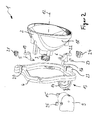
- a headlight 1 for vehicles essentially has a reflector 2, a light source 3 arranged in the central area of the reflector 2 and a support frame 4, on which the reflector 2 by means of an upper bearing element 5 and by means of a lower bearing element 6 is rotatably supported about a vertical pivot axis 7.
- an adjusting device 8 is provided, which consists essentially of a servomotor 9, a provided with electronic components control board 10 and a linearly movable adjusting element 11.
- the control board 10 can be integrated in the housing of the servomotor 9.
- the servo motor 9 is arranged transversely to an optical axis 12 of the reflector 2, preferably in the horizontal direction, oriented and connected by means of a bayonet closure 13 with a protruding from a rear side of the support frame 4 holding part 14.
- the holding part 14 is preferably integrally connected to the support frame 4.
- the adjusting device 8 with the servomotor 9 is arranged for thermal reasons in a lower region of the headlamp.
- the servomotor 9 may be supported by means of a screw connection to the holding part 14.
- an opening in the direction of travel driver 15 is arranged, which is rectangular in shape with an opening whose normal vector is parallel to the optical axis 12.
- the open in the direction of travel driver 15 is formed O-shaped.
- the pin 16 is barrel-shaped, wherein it forms a relatively small contact surface 17 with an inner side of the rectangular driver 15, see Figure 4.
- the upper bearing element 5 and the lower bearing element 6 are by means of screwing in an upper region or lower region with a rear wall 18 of the reflector 2 connected.
- a vertically projecting upward pin 19 of the upper bearing element 5 engages in an opening of a detent connected to a receptacle 20 of the support frame 4 bearing shell 21 a.
- the pin 19 is fixed in the vertical direction movable in the upper bearing shell 21.
- the lower bearing element 6 has a vertically projecting downwardly projecting joint ball 22, which is rotatably mounted about the vertical pivot axis 7 in a latching manner in a lower receptacle 23 of the support frame 4 lower bearing shell 24.
- the upper bearing element 5 and the lower bearing element 6 are screwed onto the rear wall 18 of the reflector 2.
- the upper bearing shell 21 is pushed onto the journal 19 of the upper bearing element 5 and, on the other hand, the lower bearing shell 24 is pushed onto the joint ball 22 of the lower bearing element 6.
- the reflector 2 is moved in the mounting direction relative to the support frame 4.
- the upper bearing shell 21 and the lower bearing shell 24 are pushed together into the receptacles 20 and 23 of the support frame 4 and respectively locked with the same.
- the pin 16 of the lower bearing element 6 engages in the driver 15 of the actuating element 11 a.
- a spring element 25 is connected by latching with the open in the direction of travel control element 11, so that the pin 16 is held free of play after his intervention in the driver 15.
- the adjusting element 11 is fastened by means of the bayonet closure 13 to the support frame 4.
- the upper bearing element 5 and the lower bearing element 6 have holes 26, are screwed through the screws, not shown, for connection to the reflector 2.
- the upper bearing element 5 and the lower bearing element 6 can be latching or integrally connected to the rear wall 18 of the reflector 2.
- the upper bearing shell 21 and the lower bearing shell 24 may alternatively be connected by screw connection or integrally with the support frame 4.
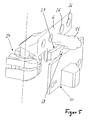
- a sensor device 30 with a magnet 27 and a Hall sensor 28 can be fastened to an underside of the lower bearing element 6, the magnet 27 cooperating with the Hall sensor 28 for detecting blockages of the electrical actuating device 8.
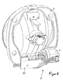
- the Hall sensor 28 can be mounted on the upright control board 10, see Figure 6.
- the control board 10 has on the one hand the sensor device 30 for the electronic blockage detection and on the other hand, the electronic control components for the servo motor 9.
- the unification allows for improved variability in the assembly of the boards with components.
- Various controls can be integrated in the adjusting device 8.
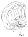
- control board 10 can also be arranged horizontally, that is to say running in the horizontal direction.
- the arrangement of the control board 10 is dependent on the available space of the vehicle.
- a microswitch with a corresponding switching cam or a light barrier for blocking detection can also be used.
- the invention allows the use of a plurality of identical parts both for a right of the vertical vehicle center plane and the left of the same arranged headlight 1.
- the reflector 2 connected to the support frame 4 can be tested as a swivel module before installation in the headlight housing as a single component.
- a further reflector preferably a high-beam reflector, may be formed on the support frame 4. This is not pivotable.
- the high beam reflector can also be arranged to be adjustable to the support frame 4.
- the high beam reflector can also be connected via a coupling mechanism with the reflector 2, so that it is designed to be swiveled.
- the driver 15 may also be formed spherically using a coupling piece with spherical pin. Between the pin of the driver and the connecting part 16 of the reflector, a coupling piece may be arranged such that a compensation of the relative movement between the driver and the connecting part 16 is given.
- connection between the actuating element 11 and the connecting part 16 can also be effected by a film hinge.
- the servomotor 9 may be rotatably supported about a vertical axis.
- the driver of the actuating element in this case has a hinged connection with the connecting part 16 of the reflector.
- connection of the actuating element 11 with the connecting part 16 of the reflector 2 by means of a worm gear with pinion or by means of a wire rope with surrounding compression spring or by means of a flexible sheet metal part done.
Abstract
Description
- Die Erfindung betrifft einen Scheinwerfer für Fahrzeuge mit einem Reflektor, mit einer im zentralen Bereich des Reflektors angeordneten Lichtquelle, mit einer Stellein-richtung zur Verstellung des Reflektors um eine vertikale Verschwenkachse enthaltend einen Stellmotor und ein linear bewegliches Stellelement, das mit einem rückseitig des Reflektors abragenden Verbindungsteil desselben in Eingriff steht, mit einem Tragrahmen, an dem der Reflektor gelenkig gelagert ist und der über ein Halteteil verfügt zur Aufnahme der Stelleinrichtung.
- Ferner betrifft die Erfindung ein Verfahren zur Herstellung eines Scheinwerfers.
- Aus der
EP 1 491 400 A2 ist ein Scheinwerfer für Fahrzeuge bekannt, der einen Reflektor und eine im zentralen Bereich des Reflektors angeordnete Lichtquelle umfasst. Der Reflektor ist an einem Tragrahmen um eine vertikale Verschwenkachse drehbar gelagert, so dass der Reflektor zur Erzeugung einer Kurventichtfunktion mittels einer ein linear bewegliches Stellelement aufweisenden Stelleinrichtung um die vertikale Verschwenkachse verschwenkbar ist. Dabei greift das linear bewegliche Stellelement in ein an einer Rückwand des Reflektors angeordnetes Verbindungsteil ein. Nachteilig an dem bekannten Scheinwerfer ist dass er durch die in Richtung einer optischen Achse des Reflektors orientierten Anordnung der Stelleinrichtung eine relativ große Bauraumtiefe benötigt. - Aus der
DE 103 39 183 A1 ist ein Scheinwerfer für Fahrzeuge bekannt, der ein nach dem Projektionsprinzip arbeitendes Lichtmodul mit einem gesonderten Lichtmodulträger aufweist, der an einem fest mit dem Gehäuse verbudenen Tragrahmen um eine vertikale Verschwenkachse verschwenkbar gelagert ist. Zwar ist die Stelleinrichtung Bauraum sparend quer zur optischen Achse des Lichtmoduls angeordnet, Durch die doppelte Ausführung eines Tragrahmens ist der Scheinwerfer jedoch relativ montageaufwendig. Insbesondere ist es erforderlich, dass die Stelleinrichtung an einem Gehäuse des Scheinwerfers befestigt werden muss. - Aufgabe der vorliegenden Erfindung ist es, einen Scheinwerfer für Fahrzeuge sowie ein Verfahren zur Herstellung desselben anzugeben, so dass mit geringem Montageaufwand eine Bauraum sparende Bereitstellung einer Kurvenlichtfunktion gewährleistet ist.
- Zur Lösung dieser Aufgabe ist die Erfindung in Verbindung mit dem Oberbegriff des Patentanspruchs 1 dadurch gekennzeichnet, dass die Stelleinrichtung quer zur optischen Achse des Reflektors angeordnet ist und dass das linear bewegliche Stellelement an einem freien Ende desselben einen in Fahrtrichtung geöffneten Mitnehmer aufweist, in dem das Verbindungsteil des Reflektors gelagert ist.
- Der besondere Vorteil der Erfindung besteht darin, dass der Scheinwerfer montagefreundlich in einer Montagerichtung (aufbauend) montierbar ist, so dass der Montageaufwand wesentlich reduziert werden kann. Zum anderen wird durch die quer eingebaute Stelleinrichtung ein Scheinwerfer mit geringer Bauraumtiefe ermöglicht. Durch die Ausbildung eines in Fahrtrichtung geöffneten Mitnehmers an einem freien Ende eines linear beweglichen Stellelementes der Stelleinrichtung erfolgt ein Ausgleich zwischen der linearen Bewegung des Stellelementes und der kreisförmigen Bewegung eines Verbindungsteils des Reflektors.
- Nach einer besonderen Ausführungsform der Erfindung ist eine Öffnung des in Fahrtrichtung geöffneten Mitnehmers derart orientiert angeordnet, dass ein Normalenvektor der Öffnung parallel zu der optischen Achse des Reflektors verläuft. Vorzugsweise ist in der Öffnung ein Federelement integriert, so dass ein Zapfen des Verbindungsteils spielfrei in der Öffnung des in Fahrtrichtung geöffneten Mitnehmers gelagert ist. Vorzugsweise weist der Zapfen eine tonnenförmige Geometrie auf, so dass bei einer Relativbewegung des Zapfens zu dem Mitnehmer die Kontaktfläche gering gehalten und die dabei entstehende Reibkraft minimiert wird. Darüber hinaus ermöglicht die tonnenförmige Geometrie des Zapfens eine Toleranzunempfindlichkeit.
- Nach einer Weiterbildung der Erfindung sind ein oberes Lagerelement und ein unteres Lagerelement durch Verschraubung mit einer Rückwand des Reflektors verbunden. Die zu dem oberen Lagerelement und dem unteren Lagerelement korrespondierende obere Lagerschale bzw. untere Lagerschale sind durch Verrastung in einer Aufnahme des Tragrahmens gehaltert. Auf einfache Weise erfolgt die Montage des Reflektors an dem Tragrahmen, nachdem die Stelleinrichtung in dem einstückig mit dem Tragrahmen verbundenen Halteteil positioniert ist, wobei die Zapfen (Gelenkkugel) des unteren Lageelementes gleichzeitig in die untere Lagerschale bzw. in den in Fahrtrichtung geöffneten Mitnehmer des Stellelementes eingreifen.
- Nach einer Weiterbildung der Erfindung kann das untere Lagerelement einen Magneten aufweisen und an dem Tragrahmen eine Sensorplatine mit einem Hallsensor befestigt sein. Auf diese Weise kann Bauraum sparend eine Blockierung des Stellmotors erkannt werden. Vorzugsweise weist die Sensorplatine zusätzlich die für den Betrieb des Stellmotors erforderlichen elektronischen Steuerbauteile auf. Durch die räumliche Zusammenführung der Steuerelektronik einerseits und der Sensorik andererseits auf einer gemeinsamen Platine kann der Bauraumbedarf weiter verringert werden.
- Zur Lösung der Aufgabe ist das erfindungsgemäße Verfahren zur Herstellung des Scheinwerfers dadurch gekennzeichnet, dass in einem einzigen Montageschritt der Reflektor unter Verrastung einer oberen Lagerschale desselben mit einer oberen Aufnahme des Tragrahmens und unter Verrastung einer unteren Lagerschale desselben mit einer unteren Aufnahme des Tragrahmens und unter schwenkbarer Kopplung des Verbindungsteils desselben mit einem Mitnehmer der Stelleinrichtung mit dem Tragrahmen verbunden wird.
- Der besondere Vorteil des erfindungsgemäßen Montageverfahrens besteht darin, dass ein Reflektor montagefreundlich in einer einzigen Montagerichtung rastend an einem Tragrahmen des Scheinwerfers montiert wird, wobei gleichzeitig eine mechanische Verbindung zwischen einem Mitnehmer einer Stelleinheit und einem Verbindungsteil des Reflektors hergestellt wird.
- Ausführungsbeispiele der Erfindung werden nachfolgend anhand der Zeichnungen näher erläutert.
- Es zeigen:
- Figur 1
- eine Rückansicht eines montierten Scheinwerfers unter Weglassung eines Gehäuses,
- Figur 2
- eine Explosionsdarstellung des erfindungsgemäßen Scheinwerfers unter Weglassung des Gehäuses,
- Figur 3
- eine rückseitige Detailansicht eines in Fahrtrichtung geöffneten Mitnehmers des linear beweglichen Stellelementes, wobei in dem Mitnehmer ein Zapfen des Verbindungsteils des Reflektors unter spielfreier Anordnung mittels eines Federelementes eingreift,
- Figur 4
- einen Horizontalschnitt durch das untere Lagerelement in der Montageposition desselben,
- Figur 5
- eine perspektivische Seitenansicht des unteren Lagerelementes mit einem integrierten Magneten, der mit einem auf einer Sensorplatine angeordneten Hallsensor zusammenwirkt,
- Figur 6
- eine Rückansicht des Scheinwerfers in der Montageposition mit einer aufrechten Platine und
- Figur 7
- eine rückseitige Darstellung des Scheinwerfers in Montageposition mit einer liegenden Platine.
- Ein Scheinwerfer 1 für Fahrzeuge weist im Wesentlichen einen Reflektor 2, eine im zentralen Bereich des Reflektors 2 angeordnete Lichtquelle 3 sowie einen Tragrahmen 4 auf, an dem der Reflektor 2 mittels eines oberen Lagerelementes 5 und mittels eines unteren Lagerelementes 6 drehbar um eine vertikale Verschwenkachse 7 gelagert ist. Zur Verschwenkung des Reflektors 2 um die vertikale Verschwenkachse 7 ist eine Stelleinrichtung 8 vorgesehen, die im Wesentlichen aus einem Stellmotor 9, einer mit elektronischen Bauteilen versehenen Steuerplatine 10 und einem linear beweglichen Stellelement 11 besteht. Hierdurch ist eine Verstellung des Reflektors 2 zur Bildung einer Kurvenlichtfunktion gewährleistet.
- Nach einer Ausführungsform gemäß Figur 1 kann die Steuerplatine 10 in dem Gehäuse des Stellmotors 9 integriert angeordnet sein. Der Stellmotor 9 ist quer zu einer optischen Achse 12 des Reflektors 2, vorzugsweise in horizontaler Richtung, orientiert angeordnet und mittels eines Bajonettverschlusses 13 mit einem von einer Rückseite des Tragrahmens 4 abragenden Halteteil 14 verbunden. Das Halteteil 14 ist vorzugsweise einstückig mit dem Tragrahmen 4 verbunden. Die Stelleinrichtung 8 mit dem Stellmotor 9 ist aus thermischen Gründen in einem unteren Bereich des Scheinwerfers angeordnet.
- Nach einer nicht dargestellten alternativen Ausführungsform kann der Stellmotor 9 mittels einer Schraubverbindung an dem Halteteil 14 gehaltert sein.
- An einem freien Ende des linear beweglichen Stellelementes 11 ist ein in Fahrtrichtung geöffneter Mitnehmer 15 angeordnet, der rechteckförmig ausgebildet ist mit einer Öffnung, deren Normalenvektor parallel zu der optischen Achse 12 verläuft. Vorzugsweise ist der in Fahrtrichtung geöffnete Mitnehmer 15 O-förmig ausgebildet. In der Montagestellung des Scheinwerfers 1 greift in die Öffnung des Mitnehmers 15 ein in horizontaler Richtung abragender Zapfen 16 ein, der von dem unteren Lagerelement 6 abragt. Der Zapfen 16 ist tonnenförmig ausgebildet, wobei er eine relativ geringe Kontaktfläche 17 mit einer Innenseite des rechteckförmigen Mitnehmers 15 bildet, siehe Figur 4.
- Das obere Lagerelement 5 und das untere Lagerelement 6 sind mittels Verschraubung in einem oberen Bereich bzw. unteren Bereich mit einer Rückwand 18 des Reflektors 2 verbunden. Ein in vertikaler Richtung nach oben abragender Zapfen 19 des oberen Lagerelementes 5 greift in eine Öffnung einer rastend mit einer Aufnahme 20 des Tragrahmens 4 verbundenen Lagerschale 21 ein. Der Zapfen 19 ist in Vertikalrichtung beweglich in der oberen Lagerschale 21 fixiert.
- Das untere Lagerelement 6 weist eine in vertikaler Richtung nach unten abragende Gelenkkugel 22 auf, die um die vertikale Verschwenkachse 7 drehbar in einer rastend in einer unteren Aufnahme 23 des Tragrahmens 4 befestigten unteren Lagerschale 24 gelagert ist.
- Zur Montage des Scheinwerfers 1 werden das obere Lagerelement 5 und das untere Lagerelement 6 auf die Rückwand 18 des Reflektors 2 geschraubt. Zum einen wird die obere Lagerschale 21 auf den Zapfen 19 des oberen Lagerelements 5 und zum anderen die untere Lagerschale 24 auf die Gelenkkugel 22 des unteren Lagerelements 6 aufgeschoben. Nun wird der Reflektor 2 in Montagerichtung relativ zu dem Tragrahmen 4 hinbewegt. Dabei werden die obere Lagerschale 21 und die untere Lagerschale 24 gemeinsam in die Aufnahmen 20 bzw. 23 des Tragrahmens 4 eingeschoben bzw. jeweils mit denselben verrastet. Ferner greift der Zapfen 16 des unteren Lagerelementes 6 in den Mitnehmer 15 des Stellelementes 11 ein.
- Darüber hinaus wird optional ein Federelement 25 durch Verrastung mit dem in Fahrtrichtung geöffneten Stellelement 11 verbunden, so dass der Zapfen 16 nach seinem Eingreifen in den Mitnehmer 15 spielfrei gehaltert ist. Das Stellelement 11 wird mittels des Bajonettverschlusses 13 an dem Tragrahmen 4 befestigt.
- Dadurch, dass die Öffnung des Mitnehmers 15 parallel zur optischen Achse und senkrecht zu dem Stellelement 11 verläuft, wobei der Zapfen 16 des Lagerelementes 6 in der Öffnung gleitend geführt ist, wird ein Ausgleich zwischen Längs- und Schwenkbewegung ermöglicht.
- Das obere Lagerelement 5 und das untere Lagerelement 6 weisen Bohrungen 26 auf, durch die nicht dargestellte Schrauben zur Verbindung mit dem Reflektor 2 einschraubbar sind.
- Nach einer nicht dargestellten Ausführungsform der Erfindung können das obere Lagerelement 5 und das untere Lagerelement 6 rastend oder einstückig mit der Rückwand 18 des Reflektors 2 verbunden sein. Die obere Lagerschale 21 und die untere Lagerschale 24 können alternativ auch durch Schraubverbindung oder einstückig mit dem Tragrahmen 4 verbunden sein.
- Nach einer Ausführungsform der Erfindung gemäß Figur 5 kann an einer Unterseite des unteren Lagerelementes 6 eine Sensorikeinrichtung 30 mit einem Magneten 27 und einem Hallsensor 28 befestigbar sein, wobei der Magnet 27 mit dem Hallsensor 28 zusammenwirkt zur Erkennung von Blockaden der elektrischen Stelleinrichtung 8.
- Der Hallsensor 28 kann auf der aufrecht angeordneten Steuerplatine 10 angebracht, siehe Figur 6. Die Steuerplatine 10 weist zum einen die Sensorikeinrichtung 30 für die elektronische Blockiererkennung und zum anderen die elektronischen Steuerbauteile für den Stellmotor 9 auf. Dadurch, dass eine Steuerelektronikplatine und eine Sensorikplatine in der Steuerplatine 10 zusammengefasst sind, ergibt sich eine Kosten sparende Vereinheitlichung, die zudem den Montageaufwand reduziert. Die Vereinheitlichung ermöglicht eine verbesserte Variabilität bei der Bestückung der Platinen mit Bauteilen. Es können verschiedene Ansteuerungen in der Stelleinrichtung 8 integriert werden.
- Nach einer alternativen Ausführungsform gemäß Figur 7 kann die Steuerplatine 10 auch liegend, das heißt in horizontaler Richtung verlaufend, angeordnet sein. Die Anordnung der Steuerplatine 10 ist abhängig von dem vorhandenen Bauraum des Fahrzeugs.
- Nach einer nicht dargestellten Ausführungsform kann statt einer Magnet/Hallsensorkombination auch ein Mikroschalter mit entsprechender Schaltnocke oder eine Lichtschranke zur Blockadeerkennung eingesetzt werden.
- Vorteilhaft ermöglicht die Erfindung die Verwendung einer Vielzahl von Gleichteilen sowohl für einen rechts der vertikalen Fahrzeugmittelebene als auch links derselben angeordnete Scheinwerfer 1. Der mit dem Tragrahmen 4 verbundene Reflektor 2 ist als Schwenkmodul vor Einbau in das Scheinwerfergehäuse als Einzelkomponente prüfbar.
- Nach einer alternativen Ausführungsform kann an den Tragrahmen 4 ein weiterer Reflektor, vorzugsweise ein Fernlichtreflektor, angeformt sein. Dieser ist nicht schwenkbar ausgeführt. Alternativ kann der Fernlichtreflektor auch justierbar zu dem Tragrahmen 4 angeordnet sein.
- Alternativ kann der Fernlichtreflektor auch über eine Koppelmechanik mit dem Reflektor 2 verbunden sein, so dass er mitschwenkbar ausgeführt ist.
- Nach einer nicht dargestellten Ausführungsform kann der Mitnehmer 15 auch kugelförmig unter Verwendung eines Koppelstückes mit kugelförmigem Zapfen ausgebildet sein. Zwischen dem Zapfen des Mitnehmers und dem Verbindungsteil 16 des Reflektors kann ein Koppelstück angeordnet sein, derart, dass ein Ausgleich der Relativbewegung zwischen dem Mitnehmer und dem Verbindungsteil 16 gegeben ist.
- Alternativ kann die Verbindung zwischen dem Stellelement 11 und dem Verbindungsteil 16 auch durch ein Filmscharnier erfolgen.
- Alternativ kann der Stellmotor 9 drehbar um eine vertikale Achse gelagert sein. Der Mitnehmer des Stellelementes hat hierbei eine gelenkige Verbindung mit dem Verbindungsteil 16 des Reflektors.
- Alternativ kann die Verbindung des Stellelementes 11 mit dem Verbindungsteil 16 des Reflektors 2 auch mittels eines Schneckengetriebes mit Ritzel oder mittels eines Drahtseils mit umgebender Druckfeder oder mittels eines flexiblen Blechteils erfolgen.
Claims (13)
- Scheinwerfer für Fahrzeuge mit einem Reflektor, mit einer im zentralen Bereich des Reflektors angeordneten Lichtquelle, mit einer Stelleinrichtung zur Verstellung des Reflektors um eine vertikale Verschwenkachse enthaltend einen Stellmotor und ein linear bewegliches Stellelement, das mit einem rückseitig des Reflektors abragenden Verbindungsteil desselben in Eingriff steht, mit einem Tragrahmen, an dem der Reflektor gelenkig gelagert ist und der über ein Halteteil verfügt zur Aufnahme der Stelleinrichtung, dadurch gekennzeichnet, dass die Stelleinrichtung (8) quer zur optischen Achse (12) des Reflektors (2) angeordnet ist und dass das linear bewegliche Stellelement (11) an einem freien Ende desselben einen in Fahrtrichtung geöffneten Mitnehmer (15) aufweist, in dem das Verbindungsteil (16) des Reflektors (2) gelagert ist.
- Scheinwerfer nach Anspruch 1, dadurch gekennzeichnet, dass der in Fahrtrichtung geöffnete Mitnehmer (15) eine Öffnung zur Aufnahme des als Zapfen (16) ausgebildeten Verbindungsteils aufweist, wobei ein Normalenvektor der Öffnung parallel zur optischen Achse (12) verläuft.
- Scheinwerfer nach Anspruch 1 oder 2, dadurch gekennzeichnet, dass die Öffnung des Mitnehmers (15) senkrecht zu dem Stellelement 11 ausgerichtet ist.
- Scheinwerfer nach einem der Ansprüche 1 bis 3, dadurch gekennzeichnet, dass der tonnenförmige Zapfen (16) einstückig mit einem unteren Lagerelement (6) verbunden ist, das über eine Gelenkkugel (22) verfügt, die in einer unteren Lagerschale (24) des Tragrahmens (4) gelagert ist, und dass das untere Lagerelement (6) in einem unteren Bereich einer Rückwand (18) des Reflektors (2) befestigbar ist.
- Scheinwerfer nach einem der Ansprüche 1 bis 4, dadurch gekennzeichnet, dass ein oberes Lagerelement (5) in einem oberen Bereich der Rückwand (18) des Reflektors (2) befestigbar ist und einen Zapfen (19) aufweist, der um die vertikale Verschwenkachse (7) verdrehbar und in Vertikalrichtung beweglich in einer oberen Lagerschale (21) gelagert ist.
- Scheinwerfer nach einem der Ansprüche 1 bis 5, dadurch gekennzeichnet, dass die obere Lagerschale (5) und/oder die untere Lagerschale (6) in einer oberen Aufnahme (20) bzw. in einer unteren Aufnahme (23) des Tragrahmens (4) eingeklipst sind.
- Scheinwerfer nach einem der Ansprüche 1 bis 6, dadurch gekennzeichnet, dass der Stellmotor (9) mittels eines Bajonettverschlusses (13) an dem Halteteil (14) des Tragrahmens (4) befestigt ist.
- Scheinwerfer nach einem der Ansprüche 1 bis 7, dadurch gekennzeichnet, dass dem in Fahrtrichtung geöffneten Mitnehmer (15) ein Federelement (25) zugeordnet ist, derart, dass der Zapfen (16) ohne Spiel in dem in Fahrtrichtung geöffneten Mitnehmer (15) gelagert ist.
- Scheinwerfer nach einem der Ansprüche 1 bis 8, dadurch gekennzeichnet, dass an dem unteren Lagerelement (6) ein Magnet (27) und an dem Tragrahmen (4) eine Steuerplatine (10) enthaltend einen Sensorik (28) befestigt ist zur Erkennung einer Blockierung des Stellmotors (9).
- Scheinwerfer nach einem der Ansprüche 1 bis 9, dadurch gekennzeichnet, dass die Steuerplatine (10) zum einen Bauelemente einer Sensorikeinichtung (30) für die elektronische Blockiererkennung und zum anderen elektronische Bauteile zur Steuerung des Stellmotors (9) aufweist.
- Scheinwerfer nach einem der Ansprüche 1 bis 10, dadurch gekennzeichnet, dass an dem Tragrahmen (4) ein zusätzlicher Reflektor angeformt ist.
- Scheinwerfer nach einem der Ansprüche 1 bis 11, dadurch gekennzeichnet, dass ein zusätzlicher Reflektor über eine mechanische Kopplung mit dem Reflektor (2) derart verbunden ist, dass der zusätzliche Reflektor zusammen mit dem Reflektor (2) gleichmäßig schwenkbar ist.
- Verfahren zur Herstellung eines Scheinwerfers nach einem der Ansprüche 1 bis 12, dadurch gekennzeichnet, dass in einem einzigen Montageschritt der Reflektor (2) unter Verrastung einer oberen Lagerschale (5) desselben mit einer oberen Aufnahme (20) des Tragrahmens (4) und unter Verrastung einer unteren Lagerschale (6) desselben mit einer unteren Aufnahme (23) des Tragrahmens (4) und unter schwenkbarer Kopplung des Verbindungsteils (16) desselben mit einem Mitnehmer (15) der Stelleinrichtung (8) mit dem Tragrahmen (4) verbunden wird.
Applications Claiming Priority (1)
| Application Number | Priority Date | Filing Date | Title |
|---|---|---|---|
| DE102006022403A DE102006022403A1 (de) | 2006-05-13 | 2006-05-13 | Scheinwerfer für Fahrzeuge und Montageverfahren |
Publications (2)
| Publication Number | Publication Date |
|---|---|
| EP1854665A1 true EP1854665A1 (de) | 2007-11-14 |
| EP1854665B1 EP1854665B1 (de) | 2009-10-21 |
Family
ID=38291291
Family Applications (1)
| Application Number | Title | Priority Date | Filing Date |
|---|---|---|---|
| EP07107888A Not-in-force EP1854665B1 (de) | 2006-05-13 | 2007-05-10 | Scheinwerfer für Fahrzeuge und Montageverfahren |
Country Status (3)
| Country | Link |
|---|---|
| EP (1) | EP1854665B1 (de) |
| AT (1) | ATE446217T1 (de) |
| DE (2) | DE102006022403A1 (de) |
Cited By (4)
| Publication number | Priority date | Publication date | Assignee | Title |
|---|---|---|---|---|
| EP2386447A1 (de) * | 2010-05-14 | 2011-11-16 | Automotive Lighting Reutlingen GmbH | Kraftfahrzeugscheinwerfer |
| EP2669113A1 (de) * | 2012-05-29 | 2013-12-04 | LG Innotek Co., Ltd. | Drehbares Stellglied |
| EP2789502A1 (de) * | 2013-04-09 | 2014-10-15 | Zizala Lichtsysteme GmbH | Fahrzeugscheinwerfer |
| WO2018215244A1 (de) * | 2017-05-24 | 2018-11-29 | Automotive Lighting Reutlingen Gmbh | Led-lichtmodul für einen kraftfahrzeugscheinwerfer |
Families Citing this family (2)
| Publication number | Priority date | Publication date | Assignee | Title |
|---|---|---|---|---|
| KR200483957Y1 (ko) | 2015-03-05 | 2017-07-14 | 에스엘 주식회사 | 차량용 램프 |
| DE102019219243A1 (de) * | 2019-12-10 | 2021-06-10 | Psa Automobiles Sa | Kraftfahrzeugscheinwerferanordnung sowie Kraftfahrzeug |
Citations (7)
| Publication number | Priority date | Publication date | Assignee | Title |
|---|---|---|---|---|
| DE10131098A1 (de) * | 2001-06-27 | 2003-01-09 | Hella Kg Hueck & Co | Scheinwerfer für Fahrzeuge |
| DE10339183A1 (de) | 2002-08-21 | 2004-03-04 | Visteon Global Technologies, Inc., Dearborn | Mehrachsenschwenkmechanismus |
| US20040090780A1 (en) * | 2002-11-07 | 2004-05-13 | John Burton | Adjuster and bracket assembly |
| EP1491400A2 (de) | 2003-06-25 | 2004-12-29 | Hella KGaA Hueck & Co. | Scheinwerfer für Fahrzeuge |
| DE10325331A1 (de) * | 2003-06-04 | 2004-12-30 | Automotive Lighting Reutlingen Gmbh | Scheinwerfer |
| EP1561639A1 (de) | 2004-02-09 | 2005-08-10 | Société industrielle de Sonceboz S.A. | Stellvorrichtung für Scheinwerfer |
| EP1591313A1 (de) * | 2004-04-27 | 2005-11-02 | Valeo Vision | Kraftfahrzeugscheinwerfer mit einer mehrfunktionalen Antrieb-Einheit |
-
2006
- 2006-05-13 DE DE102006022403A patent/DE102006022403A1/de not_active Withdrawn
-
2007
- 2007-05-10 AT AT07107888T patent/ATE446217T1/de active
- 2007-05-10 EP EP07107888A patent/EP1854665B1/de not_active Not-in-force
- 2007-05-10 DE DE502007001769T patent/DE502007001769D1/de active Active
Patent Citations (7)
| Publication number | Priority date | Publication date | Assignee | Title |
|---|---|---|---|---|
| DE10131098A1 (de) * | 2001-06-27 | 2003-01-09 | Hella Kg Hueck & Co | Scheinwerfer für Fahrzeuge |
| DE10339183A1 (de) | 2002-08-21 | 2004-03-04 | Visteon Global Technologies, Inc., Dearborn | Mehrachsenschwenkmechanismus |
| US20040090780A1 (en) * | 2002-11-07 | 2004-05-13 | John Burton | Adjuster and bracket assembly |
| DE10325331A1 (de) * | 2003-06-04 | 2004-12-30 | Automotive Lighting Reutlingen Gmbh | Scheinwerfer |
| EP1491400A2 (de) | 2003-06-25 | 2004-12-29 | Hella KGaA Hueck & Co. | Scheinwerfer für Fahrzeuge |
| EP1561639A1 (de) | 2004-02-09 | 2005-08-10 | Société industrielle de Sonceboz S.A. | Stellvorrichtung für Scheinwerfer |
| EP1591313A1 (de) * | 2004-04-27 | 2005-11-02 | Valeo Vision | Kraftfahrzeugscheinwerfer mit einer mehrfunktionalen Antrieb-Einheit |
Cited By (10)
| Publication number | Priority date | Publication date | Assignee | Title |
|---|---|---|---|---|
| EP2386447A1 (de) * | 2010-05-14 | 2011-11-16 | Automotive Lighting Reutlingen GmbH | Kraftfahrzeugscheinwerfer |
| CN102294974A (zh) * | 2010-05-14 | 2011-12-28 | 汽车照明罗伊特林根有限公司 | 汽车前照灯 |
| EP2669113A1 (de) * | 2012-05-29 | 2013-12-04 | LG Innotek Co., Ltd. | Drehbares Stellglied |
| KR20130133380A (ko) * | 2012-05-29 | 2013-12-09 | 엘지이노텍 주식회사 | 스위블 액츄에이터 |
| CN103453095A (zh) * | 2012-05-29 | 2013-12-18 | Lg伊诺特有限公司 | 旋转致动器 |
| CN103453095B (zh) * | 2012-05-29 | 2016-04-20 | Lg伊诺特有限公司 | 旋转致动器 |
| US9593751B2 (en) | 2012-05-29 | 2017-03-14 | Lg Innotek Co., Ltd. | Swiveling actuator |
| EP2789502A1 (de) * | 2013-04-09 | 2014-10-15 | Zizala Lichtsysteme GmbH | Fahrzeugscheinwerfer |
| WO2018215244A1 (de) * | 2017-05-24 | 2018-11-29 | Automotive Lighting Reutlingen Gmbh | Led-lichtmodul für einen kraftfahrzeugscheinwerfer |
| CN110945281A (zh) * | 2017-05-24 | 2020-03-31 | 汽车照明罗伊特林根有限公司 | 用于机动车前照灯的led光模块 |
Also Published As
| Publication number | Publication date |
|---|---|
| DE102006022403A1 (de) | 2007-11-22 |
| EP1854665B1 (de) | 2009-10-21 |
| ATE446217T1 (de) | 2009-11-15 |
| DE502007001769D1 (de) | 2009-12-03 |
Similar Documents
| Publication | Publication Date | Title |
|---|---|---|
| EP1854665B1 (de) | Scheinwerfer für Fahrzeuge und Montageverfahren | |
| DE2847908C3 (de) | Blinkleuchte-Scheinwerfer-Befestigung in Kraftfahrzeugkarosserien | |
| WO2006105969A1 (de) | Scheinwerfer für fahrzeuge | |
| EP2383146A1 (de) | Vorrichtung zum Verstellen eines Lichtmoduls | |
| DE10154080A1 (de) | Halterung für ein justierbares Gehäuse | |
| DE102013113675B4 (de) | Paneeleinspannvorrichtung für ein Fahrzeug | |
| DE102012022082B4 (de) | Scheinwerfer mit Blende für Fahrzeuge | |
| DE102005031809A1 (de) | Scheinwerfer für Fahrzeuge | |
| DE10002956A1 (de) | Scheinwerferbaugruppe für ein Kraftfahrzeug | |
| DE102005047731B4 (de) | Verriegelungseinrichtung für Kraftfahrzeugsitze | |
| EP1852283B1 (de) | Elektrische Verbindungsvorrichtung für eine Anhängerkupplung | |
| DE3741907A1 (de) | Einschwenkbare scheinwerferanordnung fuer fahrzeuge | |
| DE3915302A1 (de) | Kippvorrichtung fuer einen fahrzeugscheinwerfer | |
| DE102006018305B4 (de) | Scheinwerfer für Fahrzeuge | |
| DE102017104287A1 (de) | Beleuchtungsvorrichtung für Fahrzeuge | |
| DE19710857A1 (de) | Scheinwerfer für Fahrzeuge | |
| EP2195214A1 (de) | Sensoranordnung | |
| DE3917813C2 (de) | ||
| DE19519651A1 (de) | Scheinwerfer für Fahrzeuge | |
| DE102006015418B4 (de) | Tankklappenmodul und Verfahren zur Herstellung eines Tankklappenmoduls | |
| DE19742816A1 (de) | Befestigungssystem für eine Blinkleuchte | |
| EP1910130B1 (de) | Spiegelkopf eines rückblickspiegels, vorzugsweise eines aussenrückblickspiegels | |
| WO2004015230A1 (de) | Zuziehvorrichtung | |
| DE102005048415A1 (de) | Scheinwerfer, insbesondere Nebelscheinwerfer | |
| DE102006018963A1 (de) | Scheinwerfer für Kraftfahrzeuge |
Legal Events
| Date | Code | Title | Description |
|---|---|---|---|
| PUAI | Public reference made under article 153(3) epc to a published international application that has entered the european phase |
Free format text: ORIGINAL CODE: 0009012 |
|
| AK | Designated contracting states |
Kind code of ref document: A1 Designated state(s): AT BE BG CH CY CZ DE DK EE ES FI FR GB GR HU IE IS IT LI LT LU LV MC MT NL PL PT RO SE SI SK TR |
|
| AX | Request for extension of the european patent |
Extension state: AL BA HR MK YU |
|
| AKX | Designation fees paid | ||
| 17P | Request for examination filed |
Effective date: 20080804 |
|
| RBV | Designated contracting states (corrected) |
Designated state(s): AT BE BG CH CY CZ DE DK EE ES FI FR GB GR HU IE IS IT LI LT LU LV MC MT NL PL PT RO SE SI SK TR |
|
| 17Q | First examination report despatched |
Effective date: 20080904 |
|
| GRAP | Despatch of communication of intention to grant a patent |
Free format text: ORIGINAL CODE: EPIDOSNIGR1 |
|
| RIN1 | Information on inventor provided before grant (corrected) |
Inventor name: SUESSELBECK, DANIEL Inventor name: BUSCHULTE, KLAUS Inventor name: BUECHNER, ARND-CLAUS |
|
| GRAS | Grant fee paid |
Free format text: ORIGINAL CODE: EPIDOSNIGR3 |
|
| GRAA | (expected) grant |
Free format text: ORIGINAL CODE: 0009210 |
|
| AK | Designated contracting states |
Kind code of ref document: B1 Designated state(s): AT BE BG CH CY CZ DE DK EE ES FI FR GB GR HU IE IS IT LI LT LU LV MC MT NL PL PT RO SE SI SK TR |
|
| REG | Reference to a national code |
Ref country code: GB Ref legal event code: FG4D Free format text: NOT ENGLISH |
|
| REG | Reference to a national code |
Ref country code: CH Ref legal event code: EP |
|
| REG | Reference to a national code |
Ref country code: IE Ref legal event code: FG4D |
|
| REF | Corresponds to: |
Ref document number: 502007001769 Country of ref document: DE Date of ref document: 20091203 Kind code of ref document: P |
|
| LTIE | Lt: invalidation of european patent or patent extension |
Effective date: 20091021 |
|
| NLV1 | Nl: lapsed or annulled due to failure to fulfill the requirements of art. 29p and 29m of the patents act | ||
| PG25 | Lapsed in a contracting state [announced via postgrant information from national office to epo] |
Ref country code: LT Free format text: LAPSE BECAUSE OF FAILURE TO SUBMIT A TRANSLATION OF THE DESCRIPTION OR TO PAY THE FEE WITHIN THE PRESCRIBED TIME-LIMIT Effective date: 20091021 Ref country code: PT Free format text: LAPSE BECAUSE OF FAILURE TO SUBMIT A TRANSLATION OF THE DESCRIPTION OR TO PAY THE FEE WITHIN THE PRESCRIBED TIME-LIMIT Effective date: 20100222 Ref country code: SE Free format text: LAPSE BECAUSE OF FAILURE TO SUBMIT A TRANSLATION OF THE DESCRIPTION OR TO PAY THE FEE WITHIN THE PRESCRIBED TIME-LIMIT Effective date: 20091021 Ref country code: ES Free format text: LAPSE BECAUSE OF FAILURE TO SUBMIT A TRANSLATION OF THE DESCRIPTION OR TO PAY THE FEE WITHIN THE PRESCRIBED TIME-LIMIT Effective date: 20100201 Ref country code: IS Free format text: LAPSE BECAUSE OF FAILURE TO SUBMIT A TRANSLATION OF THE DESCRIPTION OR TO PAY THE FEE WITHIN THE PRESCRIBED TIME-LIMIT Effective date: 20100221 Ref country code: FI Free format text: LAPSE BECAUSE OF FAILURE TO SUBMIT A TRANSLATION OF THE DESCRIPTION OR TO PAY THE FEE WITHIN THE PRESCRIBED TIME-LIMIT Effective date: 20091021 |
|
| REG | Reference to a national code |
Ref country code: IE Ref legal event code: FD4D |
|
| PG25 | Lapsed in a contracting state [announced via postgrant information from national office to epo] |
Ref country code: LV Free format text: LAPSE BECAUSE OF FAILURE TO SUBMIT A TRANSLATION OF THE DESCRIPTION OR TO PAY THE FEE WITHIN THE PRESCRIBED TIME-LIMIT Effective date: 20091021 Ref country code: PL Free format text: LAPSE BECAUSE OF FAILURE TO SUBMIT A TRANSLATION OF THE DESCRIPTION OR TO PAY THE FEE WITHIN THE PRESCRIBED TIME-LIMIT Effective date: 20091021 Ref country code: SI Free format text: LAPSE BECAUSE OF FAILURE TO SUBMIT A TRANSLATION OF THE DESCRIPTION OR TO PAY THE FEE WITHIN THE PRESCRIBED TIME-LIMIT Effective date: 20091021 |
|
| PG25 | Lapsed in a contracting state [announced via postgrant information from national office to epo] |
Ref country code: DK Free format text: LAPSE BECAUSE OF FAILURE TO SUBMIT A TRANSLATION OF THE DESCRIPTION OR TO PAY THE FEE WITHIN THE PRESCRIBED TIME-LIMIT Effective date: 20091021 Ref country code: EE Free format text: LAPSE BECAUSE OF FAILURE TO SUBMIT A TRANSLATION OF THE DESCRIPTION OR TO PAY THE FEE WITHIN THE PRESCRIBED TIME-LIMIT Effective date: 20091021 Ref country code: RO Free format text: LAPSE BECAUSE OF FAILURE TO SUBMIT A TRANSLATION OF THE DESCRIPTION OR TO PAY THE FEE WITHIN THE PRESCRIBED TIME-LIMIT Effective date: 20091021 Ref country code: IE Free format text: LAPSE BECAUSE OF FAILURE TO SUBMIT A TRANSLATION OF THE DESCRIPTION OR TO PAY THE FEE WITHIN THE PRESCRIBED TIME-LIMIT Effective date: 20091021 Ref country code: BG Free format text: LAPSE BECAUSE OF FAILURE TO SUBMIT A TRANSLATION OF THE DESCRIPTION OR TO PAY THE FEE WITHIN THE PRESCRIBED TIME-LIMIT Effective date: 20100121 |
|
| PLBE | No opposition filed within time limit |
Free format text: ORIGINAL CODE: 0009261 |
|
| STAA | Information on the status of an ep patent application or granted ep patent |
Free format text: STATUS: NO OPPOSITION FILED WITHIN TIME LIMIT |
|
| PG25 | Lapsed in a contracting state [announced via postgrant information from national office to epo] |
Ref country code: CZ Free format text: LAPSE BECAUSE OF FAILURE TO SUBMIT A TRANSLATION OF THE DESCRIPTION OR TO PAY THE FEE WITHIN THE PRESCRIBED TIME-LIMIT Effective date: 20091021 Ref country code: SK Free format text: LAPSE BECAUSE OF FAILURE TO SUBMIT A TRANSLATION OF THE DESCRIPTION OR TO PAY THE FEE WITHIN THE PRESCRIBED TIME-LIMIT Effective date: 20091021 |
|
| 26N | No opposition filed |
Effective date: 20100722 |
|
| PG25 | Lapsed in a contracting state [announced via postgrant information from national office to epo] |
Ref country code: GR Free format text: LAPSE BECAUSE OF FAILURE TO SUBMIT A TRANSLATION OF THE DESCRIPTION OR TO PAY THE FEE WITHIN THE PRESCRIBED TIME-LIMIT Effective date: 20100122 |
|
| BERE | Be: lapsed |
Owner name: HELLA KGAA HUECK & CO. Effective date: 20100531 |
|
| PG25 | Lapsed in a contracting state [announced via postgrant information from national office to epo] |
Ref country code: MC Free format text: LAPSE BECAUSE OF NON-PAYMENT OF DUE FEES Effective date: 20100531 |
|
| PG25 | Lapsed in a contracting state [announced via postgrant information from national office to epo] |
Ref country code: IT Free format text: LAPSE BECAUSE OF FAILURE TO SUBMIT A TRANSLATION OF THE DESCRIPTION OR TO PAY THE FEE WITHIN THE PRESCRIBED TIME-LIMIT Effective date: 20091021 Ref country code: BE Free format text: LAPSE BECAUSE OF NON-PAYMENT OF DUE FEES Effective date: 20100531 |
|
| PG25 | Lapsed in a contracting state [announced via postgrant information from national office to epo] |
Ref country code: MT Free format text: LAPSE BECAUSE OF FAILURE TO SUBMIT A TRANSLATION OF THE DESCRIPTION OR TO PAY THE FEE WITHIN THE PRESCRIBED TIME-LIMIT Effective date: 20091021 |
|
| REG | Reference to a national code |
Ref country code: CH Ref legal event code: PL |
|
| PG25 | Lapsed in a contracting state [announced via postgrant information from national office to epo] |
Ref country code: LI Free format text: LAPSE BECAUSE OF NON-PAYMENT OF DUE FEES Effective date: 20110531 Ref country code: CH Free format text: LAPSE BECAUSE OF NON-PAYMENT OF DUE FEES Effective date: 20110531 |
|
| PG25 | Lapsed in a contracting state [announced via postgrant information from national office to epo] |
Ref country code: CY Free format text: LAPSE BECAUSE OF FAILURE TO SUBMIT A TRANSLATION OF THE DESCRIPTION OR TO PAY THE FEE WITHIN THE PRESCRIBED TIME-LIMIT Effective date: 20091021 |
|
| PGFP | Annual fee paid to national office [announced via postgrant information from national office to epo] |
Ref country code: FR Payment date: 20120608 Year of fee payment: 6 Ref country code: GB Payment date: 20120509 Year of fee payment: 6 |
|
| PG25 | Lapsed in a contracting state [announced via postgrant information from national office to epo] |
Ref country code: NL Free format text: LAPSE BECAUSE OF FAILURE TO SUBMIT A TRANSLATION OF THE DESCRIPTION OR TO PAY THE FEE WITHIN THE PRESCRIBED TIME-LIMIT Effective date: 20091021 Ref country code: HU Free format text: LAPSE BECAUSE OF FAILURE TO SUBMIT A TRANSLATION OF THE DESCRIPTION OR TO PAY THE FEE WITHIN THE PRESCRIBED TIME-LIMIT Effective date: 20100422 Ref country code: LU Free format text: LAPSE BECAUSE OF NON-PAYMENT OF DUE FEES Effective date: 20100510 |
|
| PG25 | Lapsed in a contracting state [announced via postgrant information from national office to epo] |
Ref country code: TR Free format text: LAPSE BECAUSE OF FAILURE TO SUBMIT A TRANSLATION OF THE DESCRIPTION OR TO PAY THE FEE WITHIN THE PRESCRIBED TIME-LIMIT Effective date: 20091021 |
|
| REG | Reference to a national code |
Ref country code: AT Ref legal event code: MM01 Ref document number: 446217 Country of ref document: AT Kind code of ref document: T Effective date: 20120510 |
|
| PG25 | Lapsed in a contracting state [announced via postgrant information from national office to epo] |
Ref country code: AT Free format text: LAPSE BECAUSE OF NON-PAYMENT OF DUE FEES Effective date: 20120510 |
|
| GBPC | Gb: european patent ceased through non-payment of renewal fee |
Effective date: 20130510 |
|
| REG | Reference to a national code |
Ref country code: FR Ref legal event code: ST Effective date: 20140131 |
|
| PG25 | Lapsed in a contracting state [announced via postgrant information from national office to epo] |
Ref country code: GB Free format text: LAPSE BECAUSE OF NON-PAYMENT OF DUE FEES Effective date: 20130510 |
|
| PG25 | Lapsed in a contracting state [announced via postgrant information from national office to epo] |
Ref country code: FR Free format text: LAPSE BECAUSE OF NON-PAYMENT OF DUE FEES Effective date: 20130531 |
|
| PGFP | Annual fee paid to national office [announced via postgrant information from national office to epo] |
Ref country code: DE Payment date: 20140507 Year of fee payment: 8 |
|
| REG | Reference to a national code |
Ref country code: DE Ref legal event code: R119 Ref document number: 502007001769 Country of ref document: DE |
|
| PG25 | Lapsed in a contracting state [announced via postgrant information from national office to epo] |
Ref country code: DE Free format text: LAPSE BECAUSE OF NON-PAYMENT OF DUE FEES Effective date: 20151201 |