EP2438639B1 - Lithium-ionen-akkumulator mit kathoden- und anodenstromkollektoren - Google Patents
Lithium-ionen-akkumulator mit kathoden- und anodenstromkollektoren Download PDFInfo
- Publication number
- EP2438639B1 EP2438639B1 EP10722897.5A EP10722897A EP2438639B1 EP 2438639 B1 EP2438639 B1 EP 2438639B1 EP 10722897 A EP10722897 A EP 10722897A EP 2438639 B1 EP2438639 B1 EP 2438639B1
- Authority
- EP
- European Patent Office
- Prior art keywords
- collector plate
- battery pack
- cathode
- housing
- battery cell
- Prior art date
- Legal status (The legal status is an assumption and is not a legal conclusion. Google has not performed a legal analysis and makes no representation as to the accuracy of the status listed.)
- Not-in-force
Links
- HBBGRARXTFLTSG-UHFFFAOYSA-N Lithium ion Chemical compound [Li+] HBBGRARXTFLTSG-UHFFFAOYSA-N 0.000 title claims description 6
- 229910001416 lithium ion Inorganic materials 0.000 title claims description 6
- PXHVJJICTQNCMI-UHFFFAOYSA-N Nickel Chemical compound [Ni] PXHVJJICTQNCMI-UHFFFAOYSA-N 0.000 claims description 12
- RYGMFSIKBFXOCR-UHFFFAOYSA-N Copper Chemical compound [Cu] RYGMFSIKBFXOCR-UHFFFAOYSA-N 0.000 claims description 6
- 229910052802 copper Inorganic materials 0.000 claims description 6
- 239000010949 copper Substances 0.000 claims description 6
- 229910052759 nickel Inorganic materials 0.000 claims description 6
- 229910001369 Brass Inorganic materials 0.000 description 6
- 239000010951 brass Substances 0.000 description 6
- 229910052751 metal Inorganic materials 0.000 description 6
- 239000002184 metal Substances 0.000 description 6
- 239000000463 material Substances 0.000 description 5
- 238000000034 method Methods 0.000 description 5
- 229910052493 LiFePO4 Inorganic materials 0.000 description 3
- 230000004888 barrier function Effects 0.000 description 3
- 238000005553 drilling Methods 0.000 description 3
- 239000000123 paper Substances 0.000 description 3
- 238000003466 welding Methods 0.000 description 3
- 238000005260 corrosion Methods 0.000 description 2
- 230000007797 corrosion Effects 0.000 description 2
- 238000012986 modification Methods 0.000 description 2
- 230000004048 modification Effects 0.000 description 2
- 229920006267 polyester film Polymers 0.000 description 2
- 229920002799 BoPET Polymers 0.000 description 1
- 239000005041 Mylar™ Substances 0.000 description 1
- 239000000853 adhesive Substances 0.000 description 1
- 230000001070 adhesive effect Effects 0.000 description 1
- 229910052782 aluminium Inorganic materials 0.000 description 1
- XAGFODPZIPBFFR-UHFFFAOYSA-N aluminium Chemical compound [Al] XAGFODPZIPBFFR-UHFFFAOYSA-N 0.000 description 1
- 238000007743 anodising Methods 0.000 description 1
- 238000005452 bending Methods 0.000 description 1
- 239000011248 coating agent Substances 0.000 description 1
- 238000000576 coating method Methods 0.000 description 1
- 238000010276 construction Methods 0.000 description 1
- 238000001816 cooling Methods 0.000 description 1
- 230000000694 effects Effects 0.000 description 1
- 238000001125 extrusion Methods 0.000 description 1
- 239000003292 glue Substances 0.000 description 1
- GELKBWJHTRAYNV-UHFFFAOYSA-K lithium iron phosphate Chemical compound [Li+].[Fe+2].[O-]P([O-])([O-])=O GELKBWJHTRAYNV-UHFFFAOYSA-K 0.000 description 1
- 238000004519 manufacturing process Methods 0.000 description 1
- 238000000465 moulding Methods 0.000 description 1
- 239000004033 plastic Substances 0.000 description 1
- 239000000843 powder Substances 0.000 description 1
- 238000004381 surface treatment Methods 0.000 description 1
Images




Classifications
-
- H—ELECTRICITY
- H01—ELECTRIC ELEMENTS
- H01M—PROCESSES OR MEANS, e.g. BATTERIES, FOR THE DIRECT CONVERSION OF CHEMICAL ENERGY INTO ELECTRICAL ENERGY
- H01M10/00—Secondary cells; Manufacture thereof
- H01M10/05—Accumulators with non-aqueous electrolyte
- H01M10/052—Li-accumulators
- H01M10/0525—Rocking-chair batteries, i.e. batteries with lithium insertion or intercalation in both electrodes; Lithium-ion batteries
-
- H—ELECTRICITY
- H01—ELECTRIC ELEMENTS
- H01M—PROCESSES OR MEANS, e.g. BATTERIES, FOR THE DIRECT CONVERSION OF CHEMICAL ENERGY INTO ELECTRICAL ENERGY
- H01M10/00—Secondary cells; Manufacture thereof
- H01M10/60—Heating or cooling; Temperature control
- H01M10/61—Types of temperature control
- H01M10/613—Cooling or keeping cold
-
- H—ELECTRICITY
- H01—ELECTRIC ELEMENTS
- H01M—PROCESSES OR MEANS, e.g. BATTERIES, FOR THE DIRECT CONVERSION OF CHEMICAL ENERGY INTO ELECTRICAL ENERGY
- H01M10/00—Secondary cells; Manufacture thereof
- H01M10/60—Heating or cooling; Temperature control
- H01M10/62—Heating or cooling; Temperature control specially adapted for specific applications
- H01M10/625—Vehicles
-
- H—ELECTRICITY
- H01—ELECTRIC ELEMENTS
- H01M—PROCESSES OR MEANS, e.g. BATTERIES, FOR THE DIRECT CONVERSION OF CHEMICAL ENERGY INTO ELECTRICAL ENERGY
- H01M10/00—Secondary cells; Manufacture thereof
- H01M10/60—Heating or cooling; Temperature control
- H01M10/64—Heating or cooling; Temperature control characterised by the shape of the cells
- H01M10/643—Cylindrical cells
-
- H—ELECTRICITY
- H01—ELECTRIC ELEMENTS
- H01M—PROCESSES OR MEANS, e.g. BATTERIES, FOR THE DIRECT CONVERSION OF CHEMICAL ENERGY INTO ELECTRICAL ENERGY
- H01M10/00—Secondary cells; Manufacture thereof
- H01M10/60—Heating or cooling; Temperature control
- H01M10/65—Means for temperature control structurally associated with the cells
- H01M10/655—Solid structures for heat exchange or heat conduction
- H01M10/6554—Rods or plates
-
- H—ELECTRICITY
- H01—ELECTRIC ELEMENTS
- H01M—PROCESSES OR MEANS, e.g. BATTERIES, FOR THE DIRECT CONVERSION OF CHEMICAL ENERGY INTO ELECTRICAL ENERGY
- H01M50/00—Constructional details or processes of manufacture of the non-active parts of electrochemical cells other than fuel cells, e.g. hybrid cells
- H01M50/20—Mountings; Secondary casings or frames; Racks, modules or packs; Suspension devices; Shock absorbers; Transport or carrying devices; Holders
-
- H—ELECTRICITY
- H01—ELECTRIC ELEMENTS
- H01M—PROCESSES OR MEANS, e.g. BATTERIES, FOR THE DIRECT CONVERSION OF CHEMICAL ENERGY INTO ELECTRICAL ENERGY
- H01M50/00—Constructional details or processes of manufacture of the non-active parts of electrochemical cells other than fuel cells, e.g. hybrid cells
- H01M50/20—Mountings; Secondary casings or frames; Racks, modules or packs; Suspension devices; Shock absorbers; Transport or carrying devices; Holders
- H01M50/204—Racks, modules or packs for multiple batteries or multiple cells
- H01M50/207—Racks, modules or packs for multiple batteries or multiple cells characterised by their shape
- H01M50/213—Racks, modules or packs for multiple batteries or multiple cells characterised by their shape adapted for cells having curved cross-section, e.g. round or elliptic
-
- H—ELECTRICITY
- H01—ELECTRIC ELEMENTS
- H01M—PROCESSES OR MEANS, e.g. BATTERIES, FOR THE DIRECT CONVERSION OF CHEMICAL ENERGY INTO ELECTRICAL ENERGY
- H01M50/00—Constructional details or processes of manufacture of the non-active parts of electrochemical cells other than fuel cells, e.g. hybrid cells
- H01M50/20—Mountings; Secondary casings or frames; Racks, modules or packs; Suspension devices; Shock absorbers; Transport or carrying devices; Holders
- H01M50/289—Mountings; Secondary casings or frames; Racks, modules or packs; Suspension devices; Shock absorbers; Transport or carrying devices; Holders characterised by spacing elements or positioning means within frames, racks or packs
- H01M50/293—Mountings; Secondary casings or frames; Racks, modules or packs; Suspension devices; Shock absorbers; Transport or carrying devices; Holders characterised by spacing elements or positioning means within frames, racks or packs characterised by the material
-
- H—ELECTRICITY
- H01—ELECTRIC ELEMENTS
- H01M—PROCESSES OR MEANS, e.g. BATTERIES, FOR THE DIRECT CONVERSION OF CHEMICAL ENERGY INTO ELECTRICAL ENERGY
- H01M50/00—Constructional details or processes of manufacture of the non-active parts of electrochemical cells other than fuel cells, e.g. hybrid cells
- H01M50/50—Current conducting connections for cells or batteries
- H01M50/502—Interconnectors for connecting terminals of adjacent batteries; Interconnectors for connecting cells outside a battery casing
-
- H—ELECTRICITY
- H01—ELECTRIC ELEMENTS
- H01M—PROCESSES OR MEANS, e.g. BATTERIES, FOR THE DIRECT CONVERSION OF CHEMICAL ENERGY INTO ELECTRICAL ENERGY
- H01M50/00—Constructional details or processes of manufacture of the non-active parts of electrochemical cells other than fuel cells, e.g. hybrid cells
- H01M50/50—Current conducting connections for cells or batteries
- H01M50/502—Interconnectors for connecting terminals of adjacent batteries; Interconnectors for connecting cells outside a battery casing
- H01M50/503—Interconnectors for connecting terminals of adjacent batteries; Interconnectors for connecting cells outside a battery casing characterised by the shape of the interconnectors
-
- H—ELECTRICITY
- H01—ELECTRIC ELEMENTS
- H01M—PROCESSES OR MEANS, e.g. BATTERIES, FOR THE DIRECT CONVERSION OF CHEMICAL ENERGY INTO ELECTRICAL ENERGY
- H01M50/00—Constructional details or processes of manufacture of the non-active parts of electrochemical cells other than fuel cells, e.g. hybrid cells
- H01M50/50—Current conducting connections for cells or batteries
- H01M50/502—Interconnectors for connecting terminals of adjacent batteries; Interconnectors for connecting cells outside a battery casing
- H01M50/514—Methods for interconnecting adjacent batteries or cells
- H01M50/516—Methods for interconnecting adjacent batteries or cells by welding, soldering or brazing
-
- H—ELECTRICITY
- H01—ELECTRIC ELEMENTS
- H01M—PROCESSES OR MEANS, e.g. BATTERIES, FOR THE DIRECT CONVERSION OF CHEMICAL ENERGY INTO ELECTRICAL ENERGY
- H01M50/00—Constructional details or processes of manufacture of the non-active parts of electrochemical cells other than fuel cells, e.g. hybrid cells
- H01M50/50—Current conducting connections for cells or batteries
- H01M50/502—Interconnectors for connecting terminals of adjacent batteries; Interconnectors for connecting cells outside a battery casing
- H01M50/521—Interconnectors for connecting terminals of adjacent batteries; Interconnectors for connecting cells outside a battery casing characterised by the material
- H01M50/524—Organic material
-
- H—ELECTRICITY
- H01—ELECTRIC ELEMENTS
- H01M—PROCESSES OR MEANS, e.g. BATTERIES, FOR THE DIRECT CONVERSION OF CHEMICAL ENERGY INTO ELECTRICAL ENERGY
- H01M50/00—Constructional details or processes of manufacture of the non-active parts of electrochemical cells other than fuel cells, e.g. hybrid cells
- H01M50/20—Mountings; Secondary casings or frames; Racks, modules or packs; Suspension devices; Shock absorbers; Transport or carrying devices; Holders
- H01M50/271—Lids or covers for the racks or secondary casings
- H01M50/273—Lids or covers for the racks or secondary casings characterised by the material
- H01M50/276—Inorganic material
-
- H—ELECTRICITY
- H01—ELECTRIC ELEMENTS
- H01M—PROCESSES OR MEANS, e.g. BATTERIES, FOR THE DIRECT CONVERSION OF CHEMICAL ENERGY INTO ELECTRICAL ENERGY
- H01M50/00—Constructional details or processes of manufacture of the non-active parts of electrochemical cells other than fuel cells, e.g. hybrid cells
- H01M50/20—Mountings; Secondary casings or frames; Racks, modules or packs; Suspension devices; Shock absorbers; Transport or carrying devices; Holders
- H01M50/296—Mountings; Secondary casings or frames; Racks, modules or packs; Suspension devices; Shock absorbers; Transport or carrying devices; Holders characterised by terminals of battery packs
-
- Y—GENERAL TAGGING OF NEW TECHNOLOGICAL DEVELOPMENTS; GENERAL TAGGING OF CROSS-SECTIONAL TECHNOLOGIES SPANNING OVER SEVERAL SECTIONS OF THE IPC; TECHNICAL SUBJECTS COVERED BY FORMER USPC CROSS-REFERENCE ART COLLECTIONS [XRACs] AND DIGESTS
- Y02—TECHNOLOGIES OR APPLICATIONS FOR MITIGATION OR ADAPTATION AGAINST CLIMATE CHANGE
- Y02E—REDUCTION OF GREENHOUSE GAS [GHG] EMISSIONS, RELATED TO ENERGY GENERATION, TRANSMISSION OR DISTRIBUTION
- Y02E60/00—Enabling technologies; Technologies with a potential or indirect contribution to GHG emissions mitigation
- Y02E60/10—Energy storage using batteries
-
- Y—GENERAL TAGGING OF NEW TECHNOLOGICAL DEVELOPMENTS; GENERAL TAGGING OF CROSS-SECTIONAL TECHNOLOGIES SPANNING OVER SEVERAL SECTIONS OF THE IPC; TECHNICAL SUBJECTS COVERED BY FORMER USPC CROSS-REFERENCE ART COLLECTIONS [XRACs] AND DIGESTS
- Y02—TECHNOLOGIES OR APPLICATIONS FOR MITIGATION OR ADAPTATION AGAINST CLIMATE CHANGE
- Y02T—CLIMATE CHANGE MITIGATION TECHNOLOGIES RELATED TO TRANSPORTATION
- Y02T10/00—Road transport of goods or passengers
- Y02T10/60—Other road transportation technologies with climate change mitigation effect
- Y02T10/70—Energy storage systems for electromobility, e.g. batteries
Definitions
- This patent relates to high energy density batteries, and more particularly to a lithium iron phosphate (LiFePO4) battery pack having cathode and anode current collectors.
- Each of the current collectors includes a collector plate, such as formed of copper or brass, and a collector plate tab, such as formed of nickel.
- US-A1-2006/0032667 describes a power supply apparatus in which a battery and a circuit wiring board or boards are electrically connected by using lead terminals.
- the present invention relates to a lithium ion battery pack comprising:
- the battery pack 100 may be a LiFePO4 battery pack suitable for inclusion in various types of electric vehicles (EVs). Such EVs include automobiles, boats, aerospace vehicles, aviation vehicles, wheelchairs, motobikes, scooters, and the like.
- EVs include automobiles, boats, aerospace vehicles, aviation vehicles, wheelchairs, motobikes, scooters, and the like.
- the battery pack 100 can also be used in hybrid vehicles (HVs), hybrid electric vehicles (HEVs), plug-in hybrid electric vehicles (PHEVs), and the like.
- HVs hybrid vehicles
- HEVs hybrid electric vehicles
- PHEVs plug-in hybrid electric vehicles
- the battery pack 100 may have a height of about 20.8 cm (8.2 inches), a width of about 8.1 cm (3.2 inches), and a length of about 12.2 cm (4.8 inches), though other dimensions are also contemplated.
- the total weight of the battery pack 100 may be about 3.0 kilograms, though other weights are also contemplated.
- the battery pack 100 includes an enclosure 101 with two external terminals 108, 110.
- the battery pack 100 includes twenty-eight cells 112, arranged in parallel and contained in the enclosure 101.
- Each of the cells 112 may be for example, an EV high energy rechargeable LiFePO4 cell with 3.2 volts and 3200 mAh, model LFP26650EV, as sold by K2 Energy Solutions, Inc, of Henderson, NV.
- the battery pack 100 has high energy density, fast recharge times, long cycle life, a flat discharge profile, and is considered to be relatively environmentally friendly.
- the cells 112 are formed in a cylindrical shape and include a conductive cathode cover 140 and a conductive anode cover 142. It will be understood that other shapes or configurations may be used depending on the application in which the battery pack 100 will be used.
- the enclosure 101 includes a housing 102 and a top 104.
- the top 104 includes two through holes 136a, 136b for receiving the external terminals 108, 1 10.
- the through holes 136a, 136b may be formed by a number of methods, including drilling through the top 104.
- the top 104 which corresponds to an open end 106 of the housing 102, is fixedly attached to the housing 102 in the final assembly after the rest of the components are placed in the housing 102.
- the top 104 is made of a material such as plastic, though other materials are possible.
- the top 104 includes tapered tabs 104a which engage the upper row of the cells 112, thereby helping to stabilize the cells 112 within the housing 101.
- the housing 102 is generally in the shape of a rectangle, is made of a material similar to that of the top 104 and may be formed by such as a molding process. However, it will be understood that other shapes or configurations are possible.
- the external terminal 108 is an anode terminal
- the other external terminal 110 is a cathode terminal.
- the anode and cathode 108, 110 may be electrically coupled to external components (not shown) of an EV.
- Each of the external terminals 108, 110 includes, for example, a base 120 having a pin 120a, a hex nut 122, a split washer 124, and a hex head cap screw 126.
- the battery pack 100 further includes an insulating paper 114 and connecting members 116, 118.
- the insulating paper 114 which corresponds generally to the shape of the open end 106 of the housing 102, is located below the top 104.
- the battery pack 100 includes two current collectors 128.
- One of the current collectors 128 is an anode current collector and the other current collector 128 is a cathode current collector.
- Each of the current collectors 128 includes two collector plate tabs 132, preferably formed of nickel, welded to a collector plate 131.
- the collector plates 131 may be formed of copper. If copper, the collector plates 131 are ultrasonically welded to the respective collector plate tabs 132. Alternatively the collector plates 131 may be formed of another metal, such as brass. Brass provides a significant cost savings without a significant loss of electrical conductivity. Additionally if the collector plates 131 are formed of brass, they may be resistance welded to the nickel collector plate tabs 132, which may provide further cost savings.
- collector plate tabs 132 could be used, in the present embodiment two are used as they are of a dimension which is commercially readily available.
- the collector plate tabs 132 are resistance welded to the cathode and anode covers 140, 142 of the cells 112. Copper and brass provides high electrical and thermal conductivity, and nickel provides corrosion and heat resistance. The use of the collector plate tabs 132 facilitates resistive welding to the cells 112. Also, the use of the collector plate 131 and the collector plate tabs 132 increases the current capacity to the cells 112 without sacrificing the voltage drop over the cells 112. More details about the construction of the current collectors 128 will be described with reference to FIG. 3 .
- FIG. 3 An alternative embodiment of the present invention is illustrated in FIG. 3 .
- a housing 102' is formed from an extrusion. This permits greater flexibility in the size of the housing 102', and thus greater flexibility in the number of cells 112 which can be contained within the housing. Rather than having a base integrally molded into the housing, in this embodiment, a discrete base 133 is utilized. Of course, the size of the current collectors 128 will be appropriately determined based upon the number of the cells 112.
- the current collector 128 includes the collector plate 131 and two collector plate tabs 132.
- the collector plate 131 is typically fabricated from a flat stock material such as a thin strip of metal, a metal grid or a perforated metal. The use of the collector plate 131 provides high electrical and thermal conductivity to the cells 112.
- the collector plate 131 includes a body portion 144 and a tab 146. The tab 146 with an approximately 90 degree bend is formed during a bending operation. As shown, the tab 146 is bent toward the body portion 144 of the collector plate 131.
- the body portion 144 is generally rectangular in shape and corresponds to the housing 102 of the battery pack 100, however other known shapes or dimensions are possible.
- the body portion 144 of the collector plate 131 includes twenty-eight holes 152, corresponding to the number of cells 112 used in the battery pack 100 ( FIG. 2 ).
- the holes 152 are also aligned with and mated with the cathode and anode covers 140, 142 of the cells 112.
- the holes 152 may be generally circular in shape, though other shapes or configurations are contemplated.
- Each of the holes 152 may have a dimension of about 1.27 cm (0.50 inches), though other dimensions are also contemplated.
- Holes 150 which have a dimension smaller than the dimension of the holes 152 are introduced on the tab 146 of the collector plate 131 for receiving the connecting members 114,116 ( FIG. 2 ).
- the holes 150, 152 may be formed by a number of methods, including drilling through the collector plate 131.
- the external terminals 108, 110 may be resistance welded to the tab 146, thereby eliminating the need for hardware to secure the external terminals 108, 110 to the tab 146.
- the underside of the top 104 is ribbed which keys the base 120 of the external terminals, restricting rotation thereof when connecting to external terminals 108, 110 to external components.
- the housings 102' is shaped to provide longitudinal recesses 102'a. These recesses provide structural integrity as well as provide passages between adjacent ones of the battery packs 100 to permit passage of cooling air as well as straps (not shown).
- the current collector 128 includes two collector plate tabs 132.
- the collector plate tabs 132 are typically fabricated from a flat stock material such as a thin strip of metal. The use of the collector plate tabs 132 provides corrosion and heat resistances effect to the cells 112.
- Each of the collector plate tabs 132 includes fourteen holes 156.
- the holes 156 are aligned with and mated with the holes 152 of the collector plate 131.
- the holes 156 of the collector plate tabs 132 may be generally round, with opposing slots to help align the current collectors 128 with the cathode and anode covers 140, 142, of the cells 112, during manufacture.
- Each of the holes 156 has a dimension smaller than the dimension of the holes 152 of the collector plate 131, though other dimensions are also contemplated.
- the holes 156 may be formed by a number of methods, including drilling through the collector plate tabs 132.
- the collector plate tabs 132 are ultrasonically welded to the collector plate 131.
- the use of the collector plate tabs 132 permits resistive welding of the collector plate 131 via the collector plate tabs 132 to the cathode and anode covers 140, 142 of the cells 112.
- the current collector 128 having the collector plate 131 and the collector plate tabs 132 increases the current capacity to the cells 112 and from an external generator (not shown) of the EV without sacrificing the voltage drop over the cells 112.
- FIG. 5 depicts a partial cross-sectional view of the battery pack 100. Only the current collectors 128 and a row of four cells 112 are illustrated. Two collector plate tabs 132 are ultrasonically welded to the collector plate 131 and in turn the collector plate tabs 132 are resistance welded to the cathode and anode covers 140, 142 of the cells 112. The through holes 152 of the collector plates 131 are aligned with and mated with the through holes 156 of the collector plate tabs 132 and the cathode and anode covers 140, 142 of the cells 112.
- the method of constructing the battery pack 100 of the present invention is as follows. First, the cells 112 are arranged in parallel. To hold the cells 112 in place, an adhesive such as glue (not shown) is applied to the body of the cells 112 to join the cells 112 together.
- the collector plate tabs 132 are placed side by side and are ultrasonically welded to respective ones of the body portion 144 of the collector plates 131 such that the holes 156 of the collector plate tabs 132 are aligned with and mated with the holes 152 of the collector plate 131.
- the tabs 146 of the collector plates 131 are fixedly attached to the pins 120 of the terminals 108, 110 via the connecting members 116, 118.
- the tabs 146 there are a number of ways to secure the tabs 146 in place, including fastening the tabs 146 to the pins 120 of the terminals 108, 110 using for example split washer 118 and screw 116.
- the insulating paper 114 is placed over the first row of the cells 112.
- the collector plate tabs 132 are resistance welded to the cathode and anode covers 140, 142 of the cells 112.
- the cells 112 attached to the current collectors 128 are placed inside the housing 102.
- the top 104 is joined to the housing 102 to seal the open end 106 of the housing 102.
- the hex nuts 122, the split washers 124, and the cap screws 126 of the terminal 108, 110 are fixed attached to the current collectors 128.
- the battery pack 100 is formed and is in electrical connection with the external components (not shown) of the EV via the terminals 108, 110.
- the individual cells 112 are electrically isolated from each other by a The individual cells 112 are electrically isolated from each other by a cardboard sleeve 160 (see Figure 2 ). Although the cells 112 are connected in parallel, the cardboard sleeve 160 provides some mechanical compliance to the battery assembly that lets the assembly accommodate thermal expansion as well as isolates adjacent ones of the cells 112 from one another during vibration.
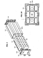
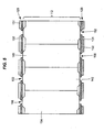
- FIG. 6 A further embodiment of the invention is illustrated in FIG. 6 .
- an opening is provided through opposing sidewalls of the housing 102', and heat conducting metal plates 170, such as of aluminum, are placed therein to draw heat away from the cells 112.
- Electrically non-conductive barriers electrically isolate the cells 112 from the plate 170.
- the barriers may be a polyester film 172, such as a Mylar film, disposed on the outer surface of the collector plates 131. Resistance welding the collector plates 131 to the collector plate tabs 132 results in a smoother outer surface of the collector plates 131. Smoother outer surfaces of the collector plates 131 may better protect the integrity of the polyester film 172 adjacent thereto.
- the barriers may be a surface treatment 174, formed such as by anodizing or powder coating the plates 170 on the side facing the cells 112.
Landscapes
- Chemical & Material Sciences (AREA)
- Chemical Kinetics & Catalysis (AREA)
- Electrochemistry (AREA)
- General Chemical & Material Sciences (AREA)
- Engineering & Computer Science (AREA)
- Manufacturing & Machinery (AREA)
- Materials Engineering (AREA)
- Connection Of Batteries Or Terminals (AREA)
- Battery Mounting, Suspending (AREA)
- Secondary Cells (AREA)
Claims (5)
- Lithium-Ionen-Akkumulator (100), der Folgendes umfasst:ein Gehäuse (102),eine Lithium-Ionen-Akkumulatorzelle (112), die ein Anoden-Akkumulatorzellen-Anschlussstück (142) und ein Kathoden-Akkumulatorzellen-Anschlussstück (140) aufweist, wobei die Akkumulatorzelle (112) in dem Gehäuse (102) angeordnet ist; underste und zweite Stromkollektoren (128), die in dem Gehäuse (102) angeordnet sind, wobei die ersten und zweiten Stromkollektoren (128) elektrisch mit den jeweiligen Anoden-(142) und Kathoden- (140) Akkumulatorzellen-Anschlussstücken in Eingriff sind, wobei die Stromkollektoren (128) jeweils eine Nickelkollektorblechlasche (132) umfassen, die eine flache Kollektorblechlaschen-Oberfläche aufweist, die mit Ultraschall an eine entsprechende Kupferkollektorblechlasche geschweißt (131) ist, die eine flache Kollektorblech-Oberfläche aufweist,wobei jede Kollektorblechlasche (132) jedes Stromkollektors (128) mit ihrem jeweiligen Akkumulatorzellen-Anschlussstück (140, 142) widerstandsverschweißt ist.
- Akkumulator (100) nach einem der vorhergehenden Ansprüche, der ferner Folgendes umfasst:eine Vielzahl von Lithium-Ionen-Akkumulatorzellen (112), die jeweils ein Anoden-Akkumulatorzellen-Anschlussstück (142) und ein Kathoden-Akkumulatorzellen-Anschlussstück (140) aufweisen, wobei die Akkumulatorzellen (112) in dem Gehäuse (102) angeordnet sind; und elektrisch parallel angeordnet sind; undwobei die ersten und zweiten Stromkollektoren (128) elektrisch mit den jeweiligen Anoden- (142) und Kathoden-(140) Akkumulatorzellen-Anschlussstücken der Akkumulatorzellen (112) in Eingriff sind.
- Akkumulator (100) nach Anspruch 1 oder 2, wobei der Akkumulator (100) ein externes Anodenanschlussstück (108) und ein externes Kathodenanschlussstück (110) umfasst und wobei die Kollektorblechlaschen (131) an ihre jeweiligen externen Anschlussstücke widerstandsgeschweißt sind.
- Akkumulator (100) nach Anspruch 1 oder 2, wobei das Gehäuse (102) ein oberes Teil (104) umfasst, das Wände aufweist, um in das externe Anodenanschlussstück (108) und das externe Kathodenanschlussstück (110) einzugreifen, um deren Drehung zu beschränken.
- Akkumulator (100) nach Anspruch 1 oder 2, wobei das Gehäuse (102) ein oberes Teil (104) umfasst, das verjüngte Blechlaschen (104a) aufweist, um stützend in die Akkumulatorzelle (112) einzugreifen.
Applications Claiming Priority (2)
| Application Number | Priority Date | Filing Date | Title |
|---|---|---|---|
| US18438909P | 2009-06-05 | 2009-06-05 | |
| PCT/US2010/037451 WO2010141853A1 (en) | 2009-06-05 | 2010-06-04 | Lithium ion battery pack having cathode and anode current collectors |
Publications (2)
| Publication Number | Publication Date |
|---|---|
| EP2438639A1 EP2438639A1 (de) | 2012-04-11 |
| EP2438639B1 true EP2438639B1 (de) | 2014-12-10 |
Family
ID=42634438
Family Applications (2)
| Application Number | Title | Priority Date | Filing Date |
|---|---|---|---|
| EP10724214.1A Not-in-force EP2438640B1 (de) | 2009-06-05 | 2010-06-04 | Lithium-ionen-akkumulator mit passivkühlung |
| EP10722897.5A Not-in-force EP2438639B1 (de) | 2009-06-05 | 2010-06-04 | Lithium-ionen-akkumulator mit kathoden- und anodenstromkollektoren |
Family Applications Before (1)
| Application Number | Title | Priority Date | Filing Date |
|---|---|---|---|
| EP10724214.1A Not-in-force EP2438640B1 (de) | 2009-06-05 | 2010-06-04 | Lithium-ionen-akkumulator mit passivkühlung |
Country Status (5)
| Country | Link |
|---|---|
| US (2) | US8703328B2 (de) |
| EP (2) | EP2438640B1 (de) |
| KR (2) | KR20120025529A (de) |
| CN (2) | CN102576830B (de) |
| WO (2) | WO2010141854A1 (de) |
Families Citing this family (47)
| Publication number | Priority date | Publication date | Assignee | Title |
|---|---|---|---|---|
| WO2011103833A2 (zh) * | 2011-04-18 | 2011-09-01 | 华为终端有限公司 | 电池、电池组件及用户设备 |
| AU2011368435B2 (en) * | 2011-05-19 | 2014-05-22 | Super B B.V. | Connection assembly for cells in a battery |
| TWI473324B (zh) * | 2011-11-21 | 2015-02-11 | Yamaha Motor Co Ltd | Battery |
| DE112012006185B4 (de) | 2012-04-05 | 2024-02-08 | Husqvarna Ab | Batteriesatz |
| TWI450433B (zh) * | 2012-07-10 | 2014-08-21 | Lite On Technology Corp | 電池裝置及供電系統 |
| CN103579678B (zh) * | 2012-08-02 | 2015-04-22 | 深圳市格瑞普电池有限公司 | 易于安装的锂离子电池组 |
| US10003067B2 (en) * | 2012-09-12 | 2018-06-19 | Gs Yuasa International Ltd. | Electric storage device and method for producing electric storage device |
| DE102012217478A1 (de) * | 2012-09-26 | 2014-03-27 | Robert Bosch Gmbh | Batteriezelle mit Stromabnehmer zur Gehäusekontaktierung |
| KR101999404B1 (ko) * | 2013-01-28 | 2019-09-27 | 삼성에스디아이 주식회사 | 배터리 팩 |
| US9966584B2 (en) * | 2013-03-11 | 2018-05-08 | Atieva, Inc. | Bus bar for battery packs |
| US9666907B2 (en) | 2013-09-03 | 2017-05-30 | Ut-Battelle, Llc | Thermal management for high-capacity large format Li-ion batteries |
| DE102013017168B4 (de) * | 2013-10-16 | 2017-07-13 | Lisa Dräxlmaier GmbH | Vorrichtung zum elektrischen Verbinden mehrerer Rundzellen sowie dazugehöriges Batteriemodul und Verfahren |
| KR101720611B1 (ko) | 2013-11-15 | 2017-03-28 | 삼성에스디아이 주식회사 | 이차 전지 |
| KR102101751B1 (ko) * | 2014-01-20 | 2020-04-20 | 삼성에스디아이 주식회사 | 이차전지 팩 |
| JP6318372B2 (ja) * | 2014-04-10 | 2018-05-09 | パナソニックIpマネジメント株式会社 | 電池ブロック、及び電池モジュール |
| US20170050529A1 (en) * | 2014-04-29 | 2017-02-23 | Hydro Québec | Bidirectional charging system for electric vehicle |
| US10121997B1 (en) | 2014-07-30 | 2018-11-06 | Google Llc | Battery module |
| DE102014111369A1 (de) | 2014-08-08 | 2016-02-11 | Lisa Dräxlmaier GmbH | Vorrichtung zum elektrischen verbinden mehrerer rundzellen und darauf basierende batterie |
| DE102014114021A1 (de) * | 2014-09-26 | 2016-03-31 | Obrist Technologies Gmbh | Batteriegehäuse |
| CN104347834B (zh) * | 2014-10-22 | 2016-06-08 | 上海中聚佳华电池科技有限公司 | 圆柱式锂离子电池模组固定架及包括其的电池组件 |
| DE102015104741A1 (de) * | 2015-03-27 | 2016-09-29 | H-Tech Ag | Batterieblock, und Verfahren zur Herstellung eines Batterieblocks |
| US10559791B2 (en) * | 2015-04-16 | 2020-02-11 | Wilhelm Neuss | Battery module |
| US20160344072A1 (en) * | 2015-05-19 | 2016-11-24 | Go-Tech Energy Co., Ltd. | Rechargeable battery module |
| WO2017034543A1 (en) | 2015-08-24 | 2017-03-02 | Elitise Llc | Battery module housing assembly |
| CN106877423A (zh) * | 2015-10-02 | 2017-06-20 | 卡梅隆文荣 | 一种汽车发动机启动器电源箱 |
| US10115943B2 (en) * | 2015-11-02 | 2018-10-30 | Korea Institute Of Energy Research | Battery packing module and battery pack |
| FR3044512B1 (fr) * | 2015-11-30 | 2018-01-05 | Lancey Energy Storage | Appareil de chauffage incluant des batteries de stockage de l'energie electrique |
| DE102016203009A1 (de) * | 2016-02-25 | 2017-08-31 | Robert Bosch Gmbh | Batteriesystem |
| CN109417145B (zh) * | 2016-06-30 | 2021-07-20 | 三洋电机株式会社 | 电池块 |
| JP6968792B2 (ja) * | 2016-06-30 | 2021-11-17 | 三洋電機株式会社 | 電池ブロック |
| US20180006279A1 (en) * | 2016-07-01 | 2018-01-04 | Optimum Battery Co., Ltd. | Current collecting board assembly and power battery pack using same |
| JP6741075B2 (ja) * | 2016-10-24 | 2020-08-19 | 株式会社村田製作所 | 電池パック |
| GB2560042B (en) | 2017-02-28 | 2020-03-25 | Jaguar Land Rover Ltd | Busbar connector |
| US10680228B2 (en) * | 2017-09-12 | 2020-06-09 | Chongqing Jinkang New Energy Vehicle Co., Ltd. | Electric vehicle battery current collector |
| KR102393343B1 (ko) * | 2017-10-31 | 2022-04-29 | 주식회사 엘지에너지솔루션 | 방열 부재가 구비된 배터리 팩 |
| JP7067098B2 (ja) * | 2018-02-09 | 2022-05-16 | トヨタ自動車株式会社 | 蓄電装置 |
| DE102018203108B4 (de) * | 2018-03-01 | 2025-12-24 | Audi Ag | Zellmodul mit mehrteiligem Gehäuse |
| KR102345048B1 (ko) | 2018-09-04 | 2021-12-28 | 주식회사 엘지에너지솔루션 | 방열 플레이트가 구비된 이차전지 팩 |
| JP6989543B2 (ja) * | 2019-02-05 | 2022-01-05 | フタバ産業株式会社 | 製造方法 |
| GB2585693B (en) * | 2019-07-12 | 2021-11-03 | Jaguar Land Rover Ltd | A battery mounting arrangement and a vehicle |
| KR102398574B1 (ko) * | 2019-10-10 | 2022-05-13 | 주식회사 엘지에너지솔루션 | 전지 모듈 및 이를 포함하는 전지 팩 |
| CN115398687A (zh) * | 2020-02-11 | 2022-11-25 | 百力通(上海)国际贸易有限公司 | 带有单侧引线接合的电池组 |
| EP4133545A1 (de) * | 2020-04-09 | 2023-02-15 | TVS Motor Company Limited | Batteriemodul |
| CN112259858B (zh) * | 2020-10-13 | 2022-05-13 | 合肥国轩高科动力能源有限公司 | 锂离子电池 |
| KR20230083811A (ko) | 2021-12-03 | 2023-06-12 | (주)시엔케이 | 전기이륜차용 배터리팩 |
| CN219163569U (zh) * | 2022-11-24 | 2023-06-09 | 广东澳运科技有限公司 | 一种储能电源 |
| WO2024238692A2 (en) * | 2023-05-15 | 2024-11-21 | Moxion Power Co. | Battery module system for mobile power station |
Family Cites Families (22)
| Publication number | Priority date | Publication date | Assignee | Title |
|---|---|---|---|---|
| US4107402A (en) * | 1977-09-22 | 1978-08-15 | Globe-Union Inc. | Battery and battery container having air-flow passages therethrough |
| CA2131358A1 (en) * | 1993-09-02 | 1995-03-03 | Jack S. Treger | Battery tester adhesive and system |
| US6187469B1 (en) * | 1998-12-28 | 2001-02-13 | HYDRO-QUéBEC | High temperature solid state hollow cylindrical battery including a plurality of solid polymer electrolyte cell |
| US6468692B1 (en) * | 1999-06-08 | 2002-10-22 | Ngk Insulators, Ltd. | Lithium secondary battery with sealed casing members |
| US6423441B1 (en) * | 2000-01-12 | 2002-07-23 | Delphi Technologies, Inc. | Battery pack signal routing system |
| JP4079572B2 (ja) * | 2000-04-14 | 2008-04-23 | 松下電器産業株式会社 | 電池パック |
| JP3850688B2 (ja) * | 2001-07-19 | 2006-11-29 | 松下電器産業株式会社 | 角形電池及び組電池の冷却装置 |
| JP3671007B2 (ja) * | 2002-01-31 | 2005-07-13 | 三洋電機株式会社 | 電源装置 |
| JP4135516B2 (ja) * | 2003-01-23 | 2008-08-20 | ソニー株式会社 | リード端子及び電源装置 |
| US6789278B2 (en) * | 2003-01-27 | 2004-09-14 | North American Manufacturing Company, Incorporated | Portable device for generating a current in a vessel |
| JP3826895B2 (ja) * | 2003-04-04 | 2006-09-27 | ソニー株式会社 | バッテリーパック |
| CN100405656C (zh) * | 2003-11-03 | 2008-07-23 | 凌沛铮 | 棱柱形电池单元,具棱柱形电池单元的电池及其制造方法 |
| CN2746545Y (zh) * | 2004-11-17 | 2005-12-14 | 加百裕工业股份有限公司 | 具有封装保护盖的电池 |
| JP5005183B2 (ja) * | 2005-04-14 | 2012-08-22 | パナソニック株式会社 | 電池間接続構造 |
| JP5061502B2 (ja) | 2006-05-20 | 2012-10-31 | 日産自動車株式会社 | 電池構造体 |
| FR2903058B1 (fr) | 2006-06-30 | 2009-04-10 | Valeo Equip Electr Moteur | Dispositif compact d'alimentation electrique pour un vehicule automobile equipe de moyens de regulation de la temperature |
| KR100886571B1 (ko) * | 2006-08-07 | 2009-03-05 | 주식회사 엘지화학 | 전지팩 케이스 |
| JP4501080B2 (ja) * | 2006-10-23 | 2010-07-14 | トヨタ自動車株式会社 | 組電池およびその製造方法 |
| JP4293226B2 (ja) * | 2006-11-02 | 2009-07-08 | ソニー株式会社 | バッテリ |
| DE102007010744B4 (de) | 2007-02-27 | 2009-01-22 | Daimler Ag | Batteriezelle einer Batterie, Zellverbund aus Batteriezellen und Verwendung mehrerer Zellen |
| DE102008034867A1 (de) * | 2008-07-26 | 2010-01-28 | Daimler Ag | Batterie, insbesondere Fahrzeugbatterie |
| CN101355144B (zh) | 2008-09-08 | 2010-07-21 | 赛恩斯能源科技有限公司 | 电池组 |
-
2010
- 2010-06-04 WO PCT/US2010/037453 patent/WO2010141854A1/en not_active Ceased
- 2010-06-04 EP EP10724214.1A patent/EP2438640B1/de not_active Not-in-force
- 2010-06-04 KR KR20117030175A patent/KR20120025529A/ko not_active Withdrawn
- 2010-06-04 CN CN201080034536.5A patent/CN102576830B/zh not_active Expired - Fee Related
- 2010-06-04 KR KR1020127000097A patent/KR101724770B1/ko not_active Expired - Fee Related
- 2010-06-04 EP EP10722897.5A patent/EP2438639B1/de not_active Not-in-force
- 2010-06-04 US US12/794,054 patent/US8703328B2/en not_active Expired - Fee Related
- 2010-06-04 CN CN2010800262625A patent/CN102460769A/zh active Pending
- 2010-06-04 US US12/793,925 patent/US20100310922A1/en not_active Abandoned
- 2010-06-04 WO PCT/US2010/037451 patent/WO2010141853A1/en not_active Ceased
Also Published As
| Publication number | Publication date |
|---|---|
| CN102576830A (zh) | 2012-07-11 |
| KR20120025529A (ko) | 2012-03-15 |
| KR20120042826A (ko) | 2012-05-03 |
| EP2438639A1 (de) | 2012-04-11 |
| US8703328B2 (en) | 2014-04-22 |
| WO2010141853A1 (en) | 2010-12-09 |
| EP2438640B1 (de) | 2015-12-16 |
| CN102460769A (zh) | 2012-05-16 |
| US20100310919A1 (en) | 2010-12-09 |
| CN102576830B (zh) | 2015-04-22 |
| KR101724770B1 (ko) | 2017-04-07 |
| WO2010141854A1 (en) | 2010-12-09 |
| US20100310922A1 (en) | 2010-12-09 |
| EP2438640A1 (de) | 2012-04-11 |
Similar Documents
| Publication | Publication Date | Title |
|---|---|---|
| EP2438639B1 (de) | Lithium-ionen-akkumulator mit kathoden- und anodenstromkollektoren | |
| KR100700277B1 (ko) | 카트리지 타입의 전지팩 | |
| KR101029019B1 (ko) | 이차전지의 충방전용 지그, 이를 포함하는 충방전용 장치 및 상기 충방전용 장치를 이용하는 이차전지의 성능 테스트 방법 | |
| RU2336601C1 (ru) | Способ изготовления модульной аккумуляторной батареи | |
| KR101371212B1 (ko) | 전지 모듈용 셀 카트리지 및 전지 모듈 | |
| EP3637503A1 (de) | Batteriemodul mit busschienenanordnung | |
| JP4630855B2 (ja) | 組電池およびその製造方法 | |
| CN100472848C (zh) | 具有交错方向结构的二次电池组 | |
| US20110064993A1 (en) | Battery array with reliable low-resistance connections | |
| KR101418629B1 (ko) | 이차전지 충방전용 지그 및 이를 이용한 충방전 장치 | |
| CN100588003C (zh) | 二次电池模块 | |
| JP2013118160A (ja) | 電池セル用ホルダ及び電池セル用ホルダを備えた組電池 | |
| KR20100044418A (ko) | 신규한 구조의 전지셀 장착 장치 | |
| JP2018503959A (ja) | バッテリセル、及び、バッテリシステム | |
| US12424691B2 (en) | Energy storage apparatus | |
| CN223124137U (zh) | 电池装置和用电装置 | |
| KR101428133B1 (ko) | 저저항 충·방전용 지그 | |
| KR20160061123A (ko) | 이차 전지의 충방전용 지그, 이를 이용한 이차전지용 충방전 장치 및 시스템 및, 이차 전지의 충방전용 지그의 배치 방법 | |
| KR20180092065A (ko) | 배터리 모듈 및 이의 조립 방법 | |
| CN120320014A (zh) | 电池装置及电池包 | |
| CN221080295U (zh) | 一种电池包及电池模组 | |
| KR101487209B1 (ko) | 전지셀의 충방전 장치 | |
| CN114552070A (zh) | 一种石墨烯加热便捷启动电源 | |
| CN220290933U (zh) | 单体电池及电池模组 | |
| CN121840034A (zh) | 电芯盖板组件和电芯 |
Legal Events
| Date | Code | Title | Description |
|---|---|---|---|
| PUAI | Public reference made under article 153(3) epc to a published international application that has entered the european phase |
Free format text: ORIGINAL CODE: 0009012 |
|
| 17P | Request for examination filed |
Effective date: 20120104 |
|
| AK | Designated contracting states |
Kind code of ref document: A1 Designated state(s): AL AT BE BG CH CY CZ DE DK EE ES FI FR GB GR HR HU IE IS IT LI LT LU LV MC MK MT NL NO PL PT RO SE SI SK SM TR |
|
| DAX | Request for extension of the european patent (deleted) | ||
| 17Q | First examination report despatched |
Effective date: 20130402 |
|
| GRAP | Despatch of communication of intention to grant a patent |
Free format text: ORIGINAL CODE: EPIDOSNIGR1 |
|
| RIC1 | Information provided on ipc code assigned before grant |
Ipc: H01M 10/625 20140101ALI20140423BHEP Ipc: H01M 2/10 20060101AFI20140423BHEP Ipc: H01M 10/0525 20100101ALI20140423BHEP Ipc: H01M 10/6554 20140101ALI20140423BHEP Ipc: H01M 2/20 20060101ALI20140423BHEP Ipc: H01M 10/613 20140101ALI20140423BHEP Ipc: H01M 10/643 20140101ALI20140423BHEP |
|
| INTG | Intention to grant announced |
Effective date: 20140516 |
|
| GRAS | Grant fee paid |
Free format text: ORIGINAL CODE: EPIDOSNIGR3 |
|
| RIN1 | Information on inventor provided before grant (corrected) |
Inventor name: SUNDERLIN, TIM, A. Inventor name: POLK, RICHARD, CORNELIUS Inventor name: STOKER, KYE, W. Inventor name: VILLARREAL, ERIC |
|
| GRAA | (expected) grant |
Free format text: ORIGINAL CODE: 0009210 |
|
| RAP1 | Party data changed (applicant data changed or rights of an application transferred) |
Owner name: K2 ENERGY SOLUTIONS, INC. |
|
| AK | Designated contracting states |
Kind code of ref document: B1 Designated state(s): AL AT BE BG CH CY CZ DE DK EE ES FI FR GB GR HR HU IE IS IT LI LT LU LV MC MK MT NL NO PL PT RO SE SI SK SM TR |
|
| REG | Reference to a national code |
Ref country code: GB Ref legal event code: FG4D |
|
| REG | Reference to a national code |
Ref country code: CH Ref legal event code: EP |
|
| REG | Reference to a national code |
Ref country code: IE Ref legal event code: FG4D |
|
| REG | Reference to a national code |
Ref country code: AT Ref legal event code: REF Ref document number: 701054 Country of ref document: AT Kind code of ref document: T Effective date: 20150115 |
|
| REG | Reference to a national code |
Ref country code: DE Ref legal event code: R096 Ref document number: 602010020876 Country of ref document: DE Effective date: 20150129 |
|
| REG | Reference to a national code |
Ref country code: AT Ref legal event code: MK05 Ref document number: 701054 Country of ref document: AT Kind code of ref document: T Effective date: 20141210 Ref country code: NL Ref legal event code: VDEP Effective date: 20141210 |
|
| REG | Reference to a national code |
Ref country code: NL Ref legal event code: VDEP Effective date: 20141210 |
|
| PG25 | Lapsed in a contracting state [announced via postgrant information from national office to epo] |
Ref country code: FI Free format text: LAPSE BECAUSE OF FAILURE TO SUBMIT A TRANSLATION OF THE DESCRIPTION OR TO PAY THE FEE WITHIN THE PRESCRIBED TIME-LIMIT Effective date: 20141210 Ref country code: LT Free format text: LAPSE BECAUSE OF FAILURE TO SUBMIT A TRANSLATION OF THE DESCRIPTION OR TO PAY THE FEE WITHIN THE PRESCRIBED TIME-LIMIT Effective date: 20141210 Ref country code: ES Free format text: LAPSE BECAUSE OF FAILURE TO SUBMIT A TRANSLATION OF THE DESCRIPTION OR TO PAY THE FEE WITHIN THE PRESCRIBED TIME-LIMIT Effective date: 20141210 Ref country code: NO Free format text: LAPSE BECAUSE OF FAILURE TO SUBMIT A TRANSLATION OF THE DESCRIPTION OR TO PAY THE FEE WITHIN THE PRESCRIBED TIME-LIMIT Effective date: 20150310 |
|
| REG | Reference to a national code |
Ref country code: LT Ref legal event code: MG4D |
|
| PG25 | Lapsed in a contracting state [announced via postgrant information from national office to epo] |
Ref country code: GR Free format text: LAPSE BECAUSE OF FAILURE TO SUBMIT A TRANSLATION OF THE DESCRIPTION OR TO PAY THE FEE WITHIN THE PRESCRIBED TIME-LIMIT Effective date: 20150311 Ref country code: AT Free format text: LAPSE BECAUSE OF FAILURE TO SUBMIT A TRANSLATION OF THE DESCRIPTION OR TO PAY THE FEE WITHIN THE PRESCRIBED TIME-LIMIT Effective date: 20141210 Ref country code: LV Free format text: LAPSE BECAUSE OF FAILURE TO SUBMIT A TRANSLATION OF THE DESCRIPTION OR TO PAY THE FEE WITHIN THE PRESCRIBED TIME-LIMIT Effective date: 20141210 Ref country code: HR Free format text: LAPSE BECAUSE OF FAILURE TO SUBMIT A TRANSLATION OF THE DESCRIPTION OR TO PAY THE FEE WITHIN THE PRESCRIBED TIME-LIMIT Effective date: 20141210 Ref country code: SE Free format text: LAPSE BECAUSE OF FAILURE TO SUBMIT A TRANSLATION OF THE DESCRIPTION OR TO PAY THE FEE WITHIN THE PRESCRIBED TIME-LIMIT Effective date: 20141210 |
|
| REG | Reference to a national code |
Ref country code: FR Ref legal event code: PLFP Year of fee payment: 6 |
|
| PG25 | Lapsed in a contracting state [announced via postgrant information from national office to epo] |
Ref country code: NL Free format text: LAPSE BECAUSE OF FAILURE TO SUBMIT A TRANSLATION OF THE DESCRIPTION OR TO PAY THE FEE WITHIN THE PRESCRIBED TIME-LIMIT Effective date: 20141210 |
|
| PG25 | Lapsed in a contracting state [announced via postgrant information from national office to epo] |
Ref country code: SK Free format text: LAPSE BECAUSE OF FAILURE TO SUBMIT A TRANSLATION OF THE DESCRIPTION OR TO PAY THE FEE WITHIN THE PRESCRIBED TIME-LIMIT Effective date: 20141210 Ref country code: CZ Free format text: LAPSE BECAUSE OF FAILURE TO SUBMIT A TRANSLATION OF THE DESCRIPTION OR TO PAY THE FEE WITHIN THE PRESCRIBED TIME-LIMIT Effective date: 20141210 Ref country code: RO Free format text: LAPSE BECAUSE OF FAILURE TO SUBMIT A TRANSLATION OF THE DESCRIPTION OR TO PAY THE FEE WITHIN THE PRESCRIBED TIME-LIMIT Effective date: 20141210 Ref country code: PT Free format text: LAPSE BECAUSE OF FAILURE TO SUBMIT A TRANSLATION OF THE DESCRIPTION OR TO PAY THE FEE WITHIN THE PRESCRIBED TIME-LIMIT Effective date: 20150410 Ref country code: EE Free format text: LAPSE BECAUSE OF FAILURE TO SUBMIT A TRANSLATION OF THE DESCRIPTION OR TO PAY THE FEE WITHIN THE PRESCRIBED TIME-LIMIT Effective date: 20141210 |
|
| PG25 | Lapsed in a contracting state [announced via postgrant information from national office to epo] |
Ref country code: PL Free format text: LAPSE BECAUSE OF FAILURE TO SUBMIT A TRANSLATION OF THE DESCRIPTION OR TO PAY THE FEE WITHIN THE PRESCRIBED TIME-LIMIT Effective date: 20141210 Ref country code: IS Free format text: LAPSE BECAUSE OF FAILURE TO SUBMIT A TRANSLATION OF THE DESCRIPTION OR TO PAY THE FEE WITHIN THE PRESCRIBED TIME-LIMIT Effective date: 20150410 |
|
| REG | Reference to a national code |
Ref country code: DE Ref legal event code: R097 Ref document number: 602010020876 Country of ref document: DE |
|
| PLBE | No opposition filed within time limit |
Free format text: ORIGINAL CODE: 0009261 |
|
| STAA | Information on the status of an ep patent application or granted ep patent |
Free format text: STATUS: NO OPPOSITION FILED WITHIN TIME LIMIT |
|
| PG25 | Lapsed in a contracting state [announced via postgrant information from national office to epo] |
Ref country code: DK Free format text: LAPSE BECAUSE OF FAILURE TO SUBMIT A TRANSLATION OF THE DESCRIPTION OR TO PAY THE FEE WITHIN THE PRESCRIBED TIME-LIMIT Effective date: 20141210 |
|
| 26N | No opposition filed |
Effective date: 20150911 |
|
| PG25 | Lapsed in a contracting state [announced via postgrant information from national office to epo] |
Ref country code: MC Free format text: LAPSE BECAUSE OF FAILURE TO SUBMIT A TRANSLATION OF THE DESCRIPTION OR TO PAY THE FEE WITHIN THE PRESCRIBED TIME-LIMIT Effective date: 20141210 |
|
| REG | Reference to a national code |
Ref country code: CH Ref legal event code: PL |
|
| PG25 | Lapsed in a contracting state [announced via postgrant information from national office to epo] |
Ref country code: LU Free format text: LAPSE BECAUSE OF FAILURE TO SUBMIT A TRANSLATION OF THE DESCRIPTION OR TO PAY THE FEE WITHIN THE PRESCRIBED TIME-LIMIT Effective date: 20150604 Ref country code: SI Free format text: LAPSE BECAUSE OF FAILURE TO SUBMIT A TRANSLATION OF THE DESCRIPTION OR TO PAY THE FEE WITHIN THE PRESCRIBED TIME-LIMIT Effective date: 20141210 |
|
| REG | Reference to a national code |
Ref country code: IE Ref legal event code: MM4A |
|
| PG25 | Lapsed in a contracting state [announced via postgrant information from national office to epo] |
Ref country code: CH Free format text: LAPSE BECAUSE OF NON-PAYMENT OF DUE FEES Effective date: 20150630 Ref country code: LI Free format text: LAPSE BECAUSE OF NON-PAYMENT OF DUE FEES Effective date: 20150630 Ref country code: IE Free format text: LAPSE BECAUSE OF NON-PAYMENT OF DUE FEES Effective date: 20150604 |
|
| REG | Reference to a national code |
Ref country code: FR Ref legal event code: PLFP Year of fee payment: 7 |
|
| PG25 | Lapsed in a contracting state [announced via postgrant information from national office to epo] |
Ref country code: BE Free format text: LAPSE BECAUSE OF FAILURE TO SUBMIT A TRANSLATION OF THE DESCRIPTION OR TO PAY THE FEE WITHIN THE PRESCRIBED TIME-LIMIT Effective date: 20141210 |
|
| PG25 | Lapsed in a contracting state [announced via postgrant information from national office to epo] |
Ref country code: MT Free format text: LAPSE BECAUSE OF FAILURE TO SUBMIT A TRANSLATION OF THE DESCRIPTION OR TO PAY THE FEE WITHIN THE PRESCRIBED TIME-LIMIT Effective date: 20141210 |
|
| REG | Reference to a national code |
Ref country code: FR Ref legal event code: PLFP Year of fee payment: 8 |
|
| PG25 | Lapsed in a contracting state [announced via postgrant information from national office to epo] |
Ref country code: HU Free format text: LAPSE BECAUSE OF FAILURE TO SUBMIT A TRANSLATION OF THE DESCRIPTION OR TO PAY THE FEE WITHIN THE PRESCRIBED TIME-LIMIT; INVALID AB INITIO Effective date: 20100604 Ref country code: SM Free format text: LAPSE BECAUSE OF FAILURE TO SUBMIT A TRANSLATION OF THE DESCRIPTION OR TO PAY THE FEE WITHIN THE PRESCRIBED TIME-LIMIT Effective date: 20141210 Ref country code: BG Free format text: LAPSE BECAUSE OF FAILURE TO SUBMIT A TRANSLATION OF THE DESCRIPTION OR TO PAY THE FEE WITHIN THE PRESCRIBED TIME-LIMIT Effective date: 20141210 |
|
| PG25 | Lapsed in a contracting state [announced via postgrant information from national office to epo] |
Ref country code: CY Free format text: LAPSE BECAUSE OF FAILURE TO SUBMIT A TRANSLATION OF THE DESCRIPTION OR TO PAY THE FEE WITHIN THE PRESCRIBED TIME-LIMIT Effective date: 20141210 |
|
| PG25 | Lapsed in a contracting state [announced via postgrant information from national office to epo] |
Ref country code: TR Free format text: LAPSE BECAUSE OF FAILURE TO SUBMIT A TRANSLATION OF THE DESCRIPTION OR TO PAY THE FEE WITHIN THE PRESCRIBED TIME-LIMIT Effective date: 20141210 |
|
| REG | Reference to a national code |
Ref country code: FR Ref legal event code: PLFP Year of fee payment: 9 |
|
| PG25 | Lapsed in a contracting state [announced via postgrant information from national office to epo] |
Ref country code: MK Free format text: LAPSE BECAUSE OF FAILURE TO SUBMIT A TRANSLATION OF THE DESCRIPTION OR TO PAY THE FEE WITHIN THE PRESCRIBED TIME-LIMIT Effective date: 20141210 |
|
| PG25 | Lapsed in a contracting state [announced via postgrant information from national office to epo] |
Ref country code: AL Free format text: LAPSE BECAUSE OF FAILURE TO SUBMIT A TRANSLATION OF THE DESCRIPTION OR TO PAY THE FEE WITHIN THE PRESCRIBED TIME-LIMIT Effective date: 20141210 |
|
| PGFP | Annual fee paid to national office [announced via postgrant information from national office to epo] |
Ref country code: FR Payment date: 20200414 Year of fee payment: 11 Ref country code: DE Payment date: 20200519 Year of fee payment: 11 |
|
| PGFP | Annual fee paid to national office [announced via postgrant information from national office to epo] |
Ref country code: IT Payment date: 20200512 Year of fee payment: 11 Ref country code: GB Payment date: 20200522 Year of fee payment: 11 |
|
| REG | Reference to a national code |
Ref country code: DE Ref legal event code: R079 Ref document number: 602010020876 Country of ref document: DE Free format text: PREVIOUS MAIN CLASS: H01M0002100000 Ipc: H01M0050200000 |
|
| REG | Reference to a national code |
Ref country code: DE Ref legal event code: R119 Ref document number: 602010020876 Country of ref document: DE |
|
| GBPC | Gb: european patent ceased through non-payment of renewal fee |
Effective date: 20210604 |
|
| PG25 | Lapsed in a contracting state [announced via postgrant information from national office to epo] |
Ref country code: GB Free format text: LAPSE BECAUSE OF NON-PAYMENT OF DUE FEES Effective date: 20210604 Ref country code: DE Free format text: LAPSE BECAUSE OF NON-PAYMENT OF DUE FEES Effective date: 20220101 |
|
| PG25 | Lapsed in a contracting state [announced via postgrant information from national office to epo] |
Ref country code: FR Free format text: LAPSE BECAUSE OF NON-PAYMENT OF DUE FEES Effective date: 20210630 |
|
| PG25 | Lapsed in a contracting state [announced via postgrant information from national office to epo] |
Ref country code: IT Free format text: LAPSE BECAUSE OF NON-PAYMENT OF DUE FEES Effective date: 20210604 |