EP2438360B1 - Appareil de détection de gaz - Google Patents
Appareil de détection de gaz Download PDFInfo
- Publication number
- EP2438360B1 EP2438360B1 EP10727127.2A EP10727127A EP2438360B1 EP 2438360 B1 EP2438360 B1 EP 2438360B1 EP 10727127 A EP10727127 A EP 10727127A EP 2438360 B1 EP2438360 B1 EP 2438360B1
- Authority
- EP
- European Patent Office
- Prior art keywords
- sample
- gas
- air
- detection apparatus
- gas detection
- Prior art date
- Legal status (The legal status is an assumption and is not a legal conclusion. Google has not performed a legal analysis and makes no representation as to the accuracy of the status listed.)
- Active
Links
Images


Classifications
-
- G—PHYSICS
- G08—SIGNALLING
- G08B—SIGNALLING OR CALLING SYSTEMS; ORDER TELEGRAPHS; ALARM SYSTEMS
- G08B17/00—Fire alarms; Alarms responsive to explosion
- G08B17/10—Actuation by presence of smoke or gases, e.g. automatic alarm devices for analysing flowing fluid materials by the use of optical means
- G08B17/117—Actuation by presence of smoke or gases, e.g. automatic alarm devices for analysing flowing fluid materials by the use of optical means by using a detection device for specific gases, e.g. combustion products, produced by the fire
-
- G—PHYSICS
- G01—MEASURING; TESTING
- G01N—INVESTIGATING OR ANALYSING MATERIALS BY DETERMINING THEIR CHEMICAL OR PHYSICAL PROPERTIES
- G01N15/00—Investigating characteristics of particles; Investigating permeability, pore-volume, or surface-area of porous materials
- G01N15/06—Investigating concentration of particle suspensions
- G01N15/0656—Investigating concentration of particle suspensions using electric, e.g. electrostatic methods or magnetic methods
-
- G—PHYSICS
- G08—SIGNALLING
- G08B—SIGNALLING OR CALLING SYSTEMS; ORDER TELEGRAPHS; ALARM SYSTEMS
- G08B21/00—Alarms responsive to a single specified undesired or abnormal condition and not otherwise provided for
- G08B21/02—Alarms for ensuring the safety of persons
- G08B21/12—Alarms for ensuring the safety of persons responsive to undesired emission of substances, e.g. pollution alarms
- G08B21/14—Toxic gas alarms
-
- G—PHYSICS
- G08—SIGNALLING
- G08B—SIGNALLING OR CALLING SYSTEMS; ORDER TELEGRAPHS; ALARM SYSTEMS
- G08B29/00—Checking or monitoring of signalling or alarm systems; Prevention or correction of operating errors, e.g. preventing unauthorised operation
- G08B29/18—Prevention or correction of operating errors
- G08B29/20—Calibration, including self-calibrating arrangements
- G08B29/22—Provisions facilitating manual calibration, e.g. input or output provisions for testing; Holding of intermittent values to permit measurement
-
- F—MECHANICAL ENGINEERING; LIGHTING; HEATING; WEAPONS; BLASTING
- F24—HEATING; RANGES; VENTILATING
- F24F—AIR-CONDITIONING; AIR-HUMIDIFICATION; VENTILATION; USE OF AIR CURRENTS FOR SCREENING
- F24F2110/00—Control inputs relating to air properties
- F24F2110/50—Air quality properties
- F24F2110/65—Concentration of specific substances or contaminants
- F24F2110/66—Volatile organic compounds [VOC]
-
- F—MECHANICAL ENGINEERING; LIGHTING; HEATING; WEAPONS; BLASTING
- F24—HEATING; RANGES; VENTILATING
- F24F—AIR-CONDITIONING; AIR-HUMIDIFICATION; VENTILATION; USE OF AIR CURRENTS FOR SCREENING
- F24F2110/00—Control inputs relating to air properties
- F24F2110/50—Air quality properties
- F24F2110/65—Concentration of specific substances or contaminants
- F24F2110/70—Carbon dioxide
-
- F—MECHANICAL ENGINEERING; LIGHTING; HEATING; WEAPONS; BLASTING
- F24—HEATING; RANGES; VENTILATING
- F24F—AIR-CONDITIONING; AIR-HUMIDIFICATION; VENTILATION; USE OF AIR CURRENTS FOR SCREENING
- F24F2110/00—Control inputs relating to air properties
- F24F2110/50—Air quality properties
- F24F2110/65—Concentration of specific substances or contaminants
- F24F2110/72—Carbon monoxide
-
- F—MECHANICAL ENGINEERING; LIGHTING; HEATING; WEAPONS; BLASTING
- F24—HEATING; RANGES; VENTILATING
- F24F—AIR-CONDITIONING; AIR-HUMIDIFICATION; VENTILATION; USE OF AIR CURRENTS FOR SCREENING
- F24F2110/00—Control inputs relating to air properties
- F24F2110/50—Air quality properties
- F24F2110/65—Concentration of specific substances or contaminants
- F24F2110/76—Oxygen
-
- Y—GENERAL TAGGING OF NEW TECHNOLOGICAL DEVELOPMENTS; GENERAL TAGGING OF CROSS-SECTIONAL TECHNOLOGIES SPANNING OVER SEVERAL SECTIONS OF THE IPC; TECHNICAL SUBJECTS COVERED BY FORMER USPC CROSS-REFERENCE ART COLLECTIONS [XRACs] AND DIGESTS
- Y02—TECHNOLOGIES OR APPLICATIONS FOR MITIGATION OR ADAPTATION AGAINST CLIMATE CHANGE
- Y02B—CLIMATE CHANGE MITIGATION TECHNOLOGIES RELATED TO BUILDINGS, e.g. HOUSING, HOUSE APPLIANCES OR RELATED END-USER APPLICATIONS
- Y02B30/00—Energy efficient heating, ventilation or air conditioning [HVAC]
- Y02B30/70—Efficient control or regulation technologies, e.g. for control of refrigerant flow, motor or heating
Definitions
- the present invention relates to detecting a condition in the environment.
- the invention relates to an apparatus and methods for detecting the presence of gases.
- the invention relates to an apparatus and methods for detecting gases indicative of a threat, for instance a gas leak or a fire.
- Gas detectors are used to detect the presence, and measure the concentration of, gases or other volatile compounds. Among other uses, they may be employed in a monitoring system to, for instance, detect the presence of
- gas detector will be predominantly described in relation to the latter (ie the prevention and detection of an undesirable fire event) for ease of understanding, this should not limit the scope of the invention. Clearly, a gas detector is also useful in other situations.
- the smoke detection system includes one or more sampling pipes connected to a common inlet manifold and an aspirator to draw air into the sampling pipes. A portion of the air drawn into the sampling pipes flows via a filter to a particle detector which has a gas sensor upstream of the smoke detector.
- an asiprated smoke detection system comprising a particle detector connected to a plurality of sampling ducts and an aspirator for drawing air through to smapling ducts into the particle detector.
- the present invention seeks to provide an improved gas detector apparatus that can be used in conjunction with air sampling pollution monitoring equipment such as an aspirated smoke detector with an associated sampling pipe network.
- the present invention provides a system for detecting a plurality of conditions in an environment in accordance with claim 1.
- the housing of the gas detection apparatus includes a duct portion configured to be interposed in a duct of a particle detection system in use.
- this allows retrofitting of the gas detection apparatus to an existing sampling duct of a particle detection.
- the flow control structure can advantageously define a curve in the sample passage and the membrane can be located on an outside portion of the curve.
- the flow control structure can include any one or more of:
- the inlet port includes a flow directing element extending into the duct of the particle detection system or duct portion of the housing to direct a sub-sample from the air sample into the sample passage.
- the flow directing element is concave-shaped.
- the outlet port is preferably also in fluid communication with the duct, such that the sub-sample is returned to the air sample flow in the duct of the particle detection system.
- the inlet port and outlet port are positioned in the airflow in the duct such that a pressure drop in the duct between the inlet port and outlet port serves to draw air through the flow path.
- the gas detection apparatus can further includes means to draw air into the input port, for example a fan, or pump can be provided.
- the gas detection apparatus can further include a secondary gas inlet configured to provide a calibration gas to the test region.
- gas provided by the secondary gas inlet to the test region is flushed from the test region through one or more associated membranes into the flow path.
- the gas detection apparatus can include a particle detection apparatus arranged to detect the presence of particles in the flow path.
- the particle detection apparatus is preferably a nephelometer arranged to transmit a beam of light across the airflow path of the case detection device.
- the flow path of the gas detection apparatus does not include a particle filter.
- Some embodiments of the gas detection apparatus can include any one or more of: an explosion proof housing; one or more flame arrestors; intrinsically safe electrical circuitry. Some embodiments of the gas detection apparatus can be intrinsically safe.
- each gas detection apparatus forms a dedicated module.
- the dedicated module is preferably adapted for placement as part of the duct system of the particle detection system.
- the gas detection apparatus is arranged to draw a sub-sample from the air sample prior to introduction of the air sample to the particle detector. It can also be arranged to return the subsample to the duct system, rather than exhausting it to atmosphere. With the gas detection system located upstream of the particle detector this approach can advantageously minimise pressure losses in the air sampling duct and/or minimise transport time delays potentially caused by the gas detection apparatus.
- the duct system includes at least one air sampling pipe including a plurality of air sample inlets arranged in series along the duct, and the gas detection apparatus being arranged to take a sub-sample from the air sampling pipe downstream of at least two air sample inlets and being calibrated with a dilution factor reflecting a diluting effect of the plurality of sample inlets on the air sampling pipe upstream of the gas detection apparatus.
- the system includes at least two gas detection apparatuses.
- each gas detection apparatus can be arranged to take a sub-sample from an air sampling pipe at a respective position and be calibrated with a corresponding dilution factor reflecting a diluting effect of the sample inlets of the air sampling pipe upstream of the gas detection apparatus's respective position.
- the system can further include at least two gas detection apparatuses being sensitive to at least one target species to be detected in an portion of the environment proximate the respective air sample inlet.
- At least two gas detection apparatuses can be positioned with respect to the duct system such that each is able to draw a sub-sample from the duct including an air sample flow drawn from a corresponding subset of air sample inlets which are not the same.
- the subset of air sample inlets corresponding to one gas detection apparatus may differ by at least one air sample inlet to the subset of air sample inlets of another particle detection apparatus.
- the subset of air sample inlets corresponding to one gas detection apparatus may not include any air sample inlets that form part of the subset of air sample inlets corresponding to another particle detection apparatus.
- At least two gas detection apparatuses can be sensitive to at least one different target species.
- the gas detection apparatus can be intrinsically safe.
- the particle detector, or any (or possibly all) component of the system can also be intrinsically safe.
- the system can include a barrier device for providing electrical power to either or both of the intrinsically safe particle detector or intrinsically safe gas sensing apparatus, or any other component of the system.
- the inventors have found that, in a gas detector apparatus including a detector test region that is separated from a gas sample region by a membrane, the inclusion of a flow control structure to direct at least a portion of the gas being sampled towards the membrane results in improvement of the gas detector apparatus.
- Sample gas flowing in the sample passage will have at least a first flow direction (ie a first net direction).
- the flow control structure will cause the sample gas flowing in the sample passage to have at least a second flow direction.
- This second flow direction may refer to only a portion of the sample gas flow, a substantial portion of the sample gas flow, or essentially all of the sample gas flow (ie a second net direction).
- the flow control structure may be the surface(s) defining the sample passage (as opposed to a distinct structure).
- the sample passage is shaped such that the sample gas changes its net flow direction from the first flow direction to a second flow direction, in these embodiments the membrane can be placed such that the first flow direction will be directed towards it.
- the flow control structure can define a bend or curve in the pipe with a membrane placed on the outside of the bend or curve.
- the first flow direction is not towards the membrane.
- the sample passage includes a deflector as the flow control structure and the cross-sectional profile of the sample passage changes along its length.
- the deflector may be (i) integral with, (ii) attached to, or (iii) separate from the surface(s) defining the sample passage.
- the surface(s) defining the sample passage result in the sample gas having a first flow direction, while the deflector causes at least a portion of the sample gas to be redirected to have at least a second flow direction that is towards the membrane.
- the deflector is necessarily proximal to the membrane such that at least some of the redirected sample gas contacts the membrane.
- the deflector is a surface or object that is aligned such that the second flow direction is towards the membrane.
- the deflector is angled with respect to the membrane (ie not parallel to the surface of the membrane that is in the sample passage).
- the deflector is inclined towards, rather than away from, the membrane.
- the deflector may be (i) a smooth or sudden narrowing / constriction of the surface(s) defining the sample passage or (ii) a bulbous protrusion from a surface defining the sample passage ((i) and (ii) are examples of integral deflectors), (iii) a flat or curved baffle extending from at least one of the surface(s) defining the sample passage (as an example of an attached deflector), or (iv) an object (such as a bead) within the sample passage but not connected to the surface(s) defining the sample passage that is obstructing the sample flow (as an example of a deflector separate from the surface(s) defining the sample passage).
- the deflector is a surface that narrows the sample passage such that the volume through which the sample gas flows past the membrane is reduced.
- this narrowing leads to an increased velocity and is thought to also lead to an increase in the turbulent nature of the sample gas flow in that region.
- Concomitant with the increased turbulence (and velocity) is an increase in the momentum flux / convection of the sample gas molecules towards the surface(s) defining the sample passage and towards the membrane. That is, an amount of sample gas molecules flowing in a first flow direction prior to entering the constriction will be caused to flow in a second flow direction towards the membrane by the narrowing (however this amount is likely to be small compared with the amount of sample gas molecules that remain flowing in the first flow direction).
- the deflector also more overtly targets the sample gas flow towards the membrane. That is, the deflector is preferably such that a substantial portion of sample gas molecules originally flowing in a first flow direction are redirected to have a second flow direction that is towards the membrane.
- the deflector may be a flat or curved surface extending from the surface(s) defining the sample passage, or a separate object, for example a rectangular prism, triangular prism, or semi-cylinder, positioned across the first flow direction of the sample gas to result in a disturbance to that flow and the second flow direction towards the membrane. That is, the flow of sample gas molecules is deflected/redirected/perturbed/disrupted by the deflector and forced to flow towards the membrane.
- the sample inlet is positionable within a flow of the bulk gas in a bulk gas duct.
- the sample inlet is adapted to direct the flow of the bulk gas into the sample passage. This is preferably achieved by a sample inlet that is concave-shaped (with respect to the direction of flow of the bulk gas). For instance, the sample inlet is scoop-shaped. Typical flow rates for the bulk gas are up to about 120 L/min.
- bulk gas may be fed into the sample inlet.
- a pump/fan/blower may be provided to direct the bulk gas into the sample inlet. In either case, desirable flow rates for the sample gas within the sample passage range from about 1 L/min to about 5 L/min.
- the sample outlet is in fluid communication with the bulk gas such that sample gas that has passed through the gas detector apparatus may be returned to its original source.
- the sample outlet is adapted to direct the sample gas into the flow of the bulk gas.
- Membranes are often used in gas detectors for filtering interference elements (eg dust) and for allowing dilution of the sample gas / target species.
- the membrane is made of any suitable material as would be known in the art.
- the membrane may be polytetraflourethylene (eg Gore-tex) or Zitex.
- the membrane is Gore-tex.
- the membrane must be porous to allow sample gas and target species to pass through to the test region and the gas detector.
- the dimensions of the membrane can be any that allow a sufficient amount of sample gas and target species to pass through (so that their concentration in the test gas is above the detection limit), and allow their passage within an acceptable timeframe (eg quickly for application in detection of an undesirable fire event).
- the amount of sample gas and target species that is capable of passing through the membrane is significantly below the detector saturation point so that gas detector replacement is required less often.
- Suitable properties are pore sizes from about 4 micron to about 20 micron, and membrane thickness from about 0.28 millimetres to about 0.56 millimetres, although the invention should not be limited by this feature. There may be more than one membrane.
- the test region of the gas detector apparatus contains a test gas, i.e. gas that is in direct contact with the detector(s).
- the test gas will be sample gas that has passed through the membrane from the sample passage.
- the test gas will be a calibration gas (such as known in the art). Calibration gas will be injected into the test region so that all the sample gas in the test region is pushed out through the membrane(s) back into the sample channel, this process effectively provides for back-flushing of the membrane to clear it of any debris, and (ii) calibration of the detector (when the test gas is a calibration gas).
- Back-flushing and calibration may be user-controlled, programmable intermittent or auto-responsive to operation conditions. The skilled person would understand the frequency at which back-flushing is required and at which calibration should be conducted.
- Each gas detector may have its own associated deflector and/or membrane, or may share a common deflector and/or membrane.
- the gas detector is preferably positioned in proximity to the membrane.
- the deflector is preferably positioned in proximity to the membrane.
- the gas detector apparatus may be operated in conjunction with a particle detector of any type known in the art, e.g. an aspirating smoke detector.
- a particle detector may be included within the gas detector apparatus of the present invention.
- the smoke and gas detector is preferably able to access a bulk gas obtained via air sampling pollution monitoring equipment such as a sampling pipe network.
- the bulk gas can be pre-filtered for particulates prior to entering the sample inlet.
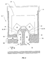
- FIG. 1 shows an exterior view of the gas detector apparatus 10.
- the gas detector apparatus 10 has a lower main housing 30 and a lid compartment 20.
- the lower end of the main housing 30, defines a duct 70 into which bulk gas can be received.
- the bulk gas duct 70 can be connected to a source of bulk gas, e.g. a pipe forming part of a sampling network of an aspirated particle detection system, an inlet or exhaust of a particle detector, a gas delivery probe in fluid communication with a duct of an HVAC system or other air source, or simply placed in fluid communication with a volume of air being monitored for the target species.
- a source of bulk gas e.g. a pipe forming part of a sampling network of an aspirated particle detection system, an inlet or exhaust of a particle detector, a gas delivery probe in fluid communication with a duct of an HVAC system or other air source, or simply placed in fluid communication with a volume of air being monitored for the target species.
- the bulk gas is introduced into the duct 70 such that a gas detector(s) within the gas detector apparatus 10 can sense the level of one or more target species in the bulk gas or a subsample taken therefrom.
- a test or calibration gas can be input into test region 62 for calibration of the gas detectors housed in the apparatus 10 and for back flushing filter membranes of the apparatus 10.
- the system can include a communications interface, e.g. USB, Ethernet, etc. to enable communication with other systems, e.g. a fire alarm system, building monitoring, HVAC etc.
- a communications interface e.g. USB, Ethernet, etc. to enable communication with other systems, e.g. a fire alarm system, building monitoring, HVAC etc.
- Figure 2 shows a schematic cross-sectional view showing more internal detail (as will be discussed later) and further demonstrating the interaction with the bulk gas duct 70.
- the gas detector apparatus 10 comprises the following main components:
- the central insert 50 also defines at least part of an inner wall of the sample passage in which a sample flows and provides in this example flow control structures, e.g. deflectors 52 and 53, to set up a desired air flow characteristic in the passage 56.
- flow control structures e.g. deflectors 52 and 53
- the central insert 50 is removable from the apparatus 10 for cleaning or changing, and can preferably be inserted into main housing 30 either from below (if no bulk gas duct 70 is present) or above (when detector cartridge 40 is absent).
- the gas detectors 42 or 43 can be any known in the art.
- the gas detector may be one for detecting the presence of at least one target species' such as SO 2 , NO 2 , CL 2 , CLO 2 , CO 2 , NH 3 , HCl, HCN, NO, O 2 , H 2 , CO, H 2 S or CH 4 .
- Other volatile organic compounds (VOCs) may also be a target species.
- VOCs volatile organic compounds
- Different gas detectors are known to be responsive to different gases. Suitable detector types might be electrochemical sensors, catalytic diffusion sensors, explosimeters, infrared point sensors, non-dispersive infrared sensors, solid state metal oxide semiconductors, and/or photo ionization detectors.
- bulk gas 72 flows in bulk gas duct 70.
- sample inlet 54 a portion is redirected into the sample passage 56 to become sample gas 57.
- the sample gas 57 is drawn towards deflector 52 in a first flow direction.
- deflector 52 Upon encountering deflector 52, at least a portion of the sample gas 57 is redirected to have a different second flow direction. This second flow direction is towards the membrane 44.
- a portion of sample gas 57 and any target species within it will pass through membrane 44, and enter test region 62. From there, the gas mixture is able to interact with the gas detector 42 (the exact nature of the interaction will depend on the type of detector) and any target species in the gas mixture will be detected.
- Flow can be described by, among other things, streamlines, streaklines and pathlines; a streamline is a curve that is instantaneously tangent to the velocity vector of the flow, a streakline is the locus of all gas molecules that have passed through a particular spatial point over a certain time frame, and a pathline is the trajectory that an individual gas molecule will have.
- streamlines, streaklines and pathlines are the same, (ii) a boundary layer exists where velocity along the pipe approaches zero, and (iii) high momentum diffusion, but low momentum convection, occurs in the direction towards the surfaces of the pipe.
- Flow in the bulk direction may be considered towards the membrane if a flow control structure is use to change the net bulk flow direction in a position proximate to the membrane.
- a flow control structure is use to change the net bulk flow direction in a position proximate to the membrane.
- the sample passage comprises an elbowed pipe and the membrane is positioned on the outside of the elbow of the pipe
- flow in the pipe (whether laminar or turbulent) is aimed towards the membrane at the elbow, hits the membrane at the elbow, and is then redirected around the corner formed by the elbow.
- the flow is 'flow control structure derived' since the pipe directs the bulk flow direction at the membrane in the elbow.
- the membrane is not positioned at the elbow, and is instead simply positioned in a wall parallel to the direction of bulk flow at a position where no change in net flow direction is being induced, and there is otherwise no flow control structures present, there will be only 'passively occurring' diffusion and convection of sample gas molecules in a direction transverse to the bulk direction of flow (ie towards the membrane). In this situation, a flow control structure resulting in a second bulk flow direction, ie a 'flow control structure derived' flow, that is towards the membrane is required.
- the flow control structure is one which provides for greater flow towards the membrane than would occur in (i) laminar flow conditions by momentum diffusion (predominantly) or (ii) turbulent flow conditions momentum convection (predominantly), and thus is one which enhances the passage of the sample gas and entrained target species through the membrane.
- sample gas 57 that does not pass through membrane 44 to detector 42 continues in sample passage 56.
- a similar scenario may occur at membrane 45 and detector 43, where the same, or an alternative target species, can be tested for. Then, any remaining sample gas 57 passes out of the gas detector apparatus 10 via sample outlet 55 and back into the bulk gas duct 70.
- test gas 63 For calibration and/or back-flushing of membrane 44 and 45, calibration gas is fed into test region 62 through test inlet 60.
- the test gas 63 will be calibration gas.
- the test gas 63 could be calibration gas (although this is usually expensive) or simply flush gas (eg ambient or preferably filtered air).
- the system requires a source of calibration gas, e.g. a gas bottle(s) with suitable pressure regulator(s), to be attached to the test inlet 60 e.g. via calibration port 64 through a solenoid valve(s).
- a duckbill valve e.g. made of an elastomeric material, which prevents gas returning to the test inlet 60 from the test region 62 if several devices are being calibrated simultaneously.
- the calibration gas delivery system is periodically activated by energising the solenoid valve(s) to inject the required zero or span calibration gas for each sensor type.
- Calibration cycles can be controlled by either internal or external means, and may be either automatic, e.g. operate on a predetermined schedule or when certain performance criteria are fulfilled, or alternatively, performed on demand in response to a user input.
- the alarms during this period are inhibited and suitable time delays are introduced to allow the sensor to settle.
- the calibration gas 63 floods the test region 62 and exits through the membranes 44 and 45. This action also serves to back-flush these membranes.
- the readings from each sensor at the time of calibration are stored and used subsequently to adjust the sample readings.
- the solenoid is then shut off to allow the sample gas 57 to again diffuse through the membranes 44 and 45 from the sample chamber 56 and fill the test region 62.
- the test region 62 is configured to have low dead volume for fast response.
- the arrangement of components described above preferably provides a sealed airflow path that returns all sample gas back to the bulk flow in the duct 70.
- this makes the detector of this embodiment particularly suited for installation in an air sampling duct of a particle detection system in a position upstream of the particle detector, e.g. as illustrated in the examples of figures 6 , 9 and 10 , because no sample air is lost from the system via leakage from the gas detection apparatus.
- a gas detection apparatus can also be used on the exhaust of a particle detector.
- figure 3 is similar to that of figure 2 except that it additionally includes an optional nephelometer 80 e.g. a photo-electric smoke detector and a fan 74.
- an optional nephelometer 80 e.g. a photo-electric smoke detector and a fan 74.
- the nephelometer 80 includes a light source 81.
- the light source is a laser (e.g. about 5 mW) or LED light source, adapted to emit a light beam across the top of sample passage 56 and along a channel 61 defined in the centre of the central insert 50.
- a light receiver (not shown), e.g. Si photodiode or similar, is placed off axis with respect to the beam and receives light that is scattered from particles, e.g. smoke entrained in the sample flow 57.
- the channel 61 is terminated in a beam dump formed by an angled reflector 82, which prevents return reflections impinging on the photodiode of the nephelometer 80.
- the fan 74 mounted in the bulk gas duct 72 is included in embodiments where an existing flow of bulk gas is not present, e.g. in stand alone systems or systems where external flows are low.
- the sample passage 56 may also be flushed by intermittently operating the fan 74, or a further fan not shown, at a rate high enough to cause flushing.
- the power for this intermittent operation of the fan, or intermittent increase speed of the fan, may be taken from an addressable fire alarm loop.
- Operation of the gas detector may be user-controlled, intermittent or continuous. In order to minimise power draw intermittent operation may be preferred.
- electrical power for the system is taken from a fire alarm loop, either directly by the apparatus 10, or via an associated particle detections system, if the gas detection apparatus is used to augment such a system.
- the duct 70 of the gas detection apparatus includes has a stepwise narrowings from its edge to centre.
- the outermost portions 91 of the duct 70 have a relatively large diameter compared to inwardly adjacent portions 92 of the duct 70, which have a narrower inside diameter.
- the central portion 93 is narrower still.
- the steps between adjacent segments in the duct can also act as a depth stop so that during installation the air sampling duct is not inserted so far into the duct 70 of the gas detection apparatus that the main air sampling duct does not interfere with the entry of air into the airflow path 56 of the gas sensing apparatus.
- a tapered duct could also be used.
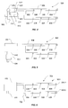
- FIG. 4 illustrates a conventional air sampling particle detection system 500.
- the system 500 includes the particle detector 502 coupled to a duct in the form of a sample pipe network 504.
- the sampling pipe network includes a plurality of air sample inlets 508.
- air is drawn into the air sample inlets 508 and into the particle detector 502 via an aspirator which typically forms part of the particle detector 502.
- Air drawn through the system 500 is exhausted back to the atmosphere via an exhaust port 510.
- the particle detector 502 in this example includes an airflow flow path 512 between its inlet 514 and exhaust port 510.
- An air sample is drawn from the environment begin monitored, along the air sampling duct and into detector flow path 512 by an aspirator 518. A part of this air sample flow is then drawn into an analysis airflow path 520 where is enters a particle detection chamber 522. Air passing through the detection chamber 522 is analysed to determine a level of particles in the air. In response to the level of particles detected and possibly other criteria the detector is configured to generate an output according to alarm and or fault logic applied by its controller.
- the detector 502 can also include additional components, including but not limited to a flow sensor 524 that is used to determine the flow rate of air passing through the particle detector, a filter 526 which serves to remove unwanted particles, e.g. dust etc. from the air flow to minimise or prevent soiling of the interior of the detection chamber 522 over time.
- a flow sensor 524 that is used to determine the flow rate of air passing through the particle detector
- a filter 526 which serves to remove unwanted particles, e.g. dust etc. from the air flow to minimise or prevent soiling of the interior of the detection chamber 522 over time.
- the detection chamber 522 can operate using any particle detection principle, including but not limited to, light scattering, light obscuration, ionisation etc.
- the particle detector could be a VESDA LaserPLUS detector from Xtralis Pty Ltd. or ICAM IAS detector also from Xtralis Pty Ltd, or some other detector.
- FIGS. 5 to 8 illustrate several uses of a gas detection apparatus.
- Figure 4 The type of air sampling particle detection system shown in Figure 4 can be augmented by using a gas detection apparatus.
- Figures 5, 6 , 9 and 10 show two of the various ways in which a particle detection system similar to that of figure 4 can be set up to include a gas detecting apparatus.
- common features to the system illustrated in Figure 4 will share common reference numerals.
- Figure 5 shows an air sampling particle detection system 600 including a particle detector 502 in fluid communication with a sampling pipe network 504.
- the exhaust 510 of the particle detector 502 is coupled to a gas detecting apparatus 602 of the type described above.
- the air which is expelled from the exhaust of the particle detector 502 passes into the gas detector 602 before finally being sent back to atmosphere via its exhaust 604.
- FIG. 6 illustrates an example of a preferred form of the present invention.
- the underlying smoke detection system is generally the same as that of Figure 4 .
- the sample pipe network 504 has a gas detector 702, as described above, positioned upstream from the particle detector along one of its branches.
- air from a first branch 504.1 of the sampling pipe network 504 is drawn directly into the particle detector 502 whereas air drawn into the second branch 504.2 of the sample pipe network 504 first passes through gas detector 702 for gas analysis prior to passing to the particle detector 502.
- gas detector 702 for gas analysis prior to passing to the particle detector 502.
- Such an embodiment may be useful in situations where localised gas release is possible. For example, in a warehouse with a refrigerant unit at one end, it may be necessary to monitor the entire space for smoke using the particle detector. However, detecting refrigerant leaks is only necessary in the area adjacent the refrigeration unit and thus, providing a relatively local gas detector unit such as that 704 is advantageous.
- FIGS 9 and 10 illustrate two further exemplary particle detection systems that include gas detection apparatuses in them.
- a particle detection system 920 which includes an aspirated particle detector 502 as described above.
- the particle detector 502 is connected to an air sampling network 504, which includes four branches 504.1, 504.2, 504.3 and 504.4, each of which have a plurality of sampling points or holes 508 into which air is drawn.
- Each branch of the duct work 504.1, 504.2, 504.3 and 504.4 includes its own gas detection apparatus, 922.1, 922.2, 922.3 and 922.4.
- Each gas detection apparatus 922.1, 922.2, 922.3 and 922.4 could be sensitive to the same or different target species, depending on the nature of the installation.
- each gas detection apparatus 922.1, 922.2, 922.3 and 922.4 will receive air from a respective subset of the sampling holes 508 of the system.
- the subset of sampling points upstream of each of the gas detection apparatuses 922.1, 922.2, 922.3 and 922.4 has a different number of air sampling holes up stream of it. This has implications for sensitivity (to samples drawn through each sampling hole) and therefore calibration or the detectors or setting of detection and/or alarm thresholds for each detector.
- FIG 10 illustrates another particle detection system 940.
- the particle detector 502 is connected to an air sampling network 504 which includes a tree-like structure.
- the network 504 has two intermediate branches 504.5 and 504.6 which subsequently branch into four branches 504.1, 504.2, 504.3 and 504.4, each of which have a plurality of sampling points or holes 508 into which air is drawn.
- Each of the intermediate branches 504.5 and 504.6 of the duct work 504 includes a gas detection apparatus, 942.1 and 942.2. As will be appreciated each gas detection apparatus receives air drawn through a respective subset of 8 sampling points located upstream of it.
- software may be provided for automatically determining calibration values for a gas detector based on one or more system characteristics, e.g. the configuration of a sampling network to which it is attached, the location in which the system is installed, and/or the likely sources of gas nearby the system.
- the software may operate in a manner similar to flow modelling software used in aspirated particle detection systems, e.g. Aspire from Xtralis Pty Ltd.
- the software is configured to calculate alarm thresholds for a gas alarm in a particular system configuration. Where the system dilutes gas samples, the threshold calculation is based on compensation for the dilution introduced by the sampling network.
- Compensation for gas distribution is also performed, such that application specific parameters are accounted for, For instance in a car park the CO distribution is homogenous and therefore a similar level of gas is introduced into every sample hole. In such cases the compensation of the alarm threshold is not required.
- the results of the alarm threshold analysis can be presented as a file for the operator to configure the instrument or can be directly downloaded into the detection equipment.
- Alarms can be set in a centralised controller or distributed at each sensor.
- the sealed configuration of the gas detection apparatus of the preferred embodiment allows the gas detection apparatus to form part of the upstream portion of the duct of the particle detection system without disadvantage in terms of pressure, leakage or transport time.
- Figure 7 illustrates a gas detector but this time it is mounted on a duct of an HVAC system.
- the gas detecting system 800 comprises a gas detector 802 mounted to an HVAC duct 804 in which air is flowing in direction of arrow 806.
- the gas detector 802 is provided with a duct probe 808 which has an upstream inlet 810 and a downstream outlet 812. The pressure difference across the inlet and outlet 810 and 812 sucks air through the gas detector 802 for analysis.
- Figure 8 shows a 900 which includes a gas detector 902 coupled directly to a sampling pipe 904 which has a plurality of sampling holes 906.
- the gas detector 902 may be provided with an internal particle detection system such as that described above. In this system it will be necessary to draw air through the sample pipe 904 to the gas detector 902. To this end, the gas detector 902 is provided with a fan 908 to draw air into it.
- the output from the gas detectors 42 and 43, and optional nephelometer 80 can be processed either alone or in combination by one or more onboard data processing systems, e.g. a microprocessor based control system, or transmitted to an external data processing system to determine whether an abnormal condition exists in the volume being monitored.
- the processing system will apply alarm and or fault logic, as known to those skilled in the art, to determine if either an abnormal gas detection event, smoke detection event, fault or other event has occurred, and whether an action e.g. raising an alarm, increasing an indicated threat level, setting off suppression systems, closing down operations of certain plant and equipment etc. needs to be performed.
- the structure of the gas detector apparatus can be made with suitable materials so as to be explosion proof or to configure it for use in an explosion risk zone. Additionally, internal components could be potted with suitable compound to prevent a flame to propagate out.
- the membranes 44 and 45 in this case would preferably be flame arrestors, for example made from sintered material of a suitable type and thickness to prevent a flame propagating from the control electronics and detectors in to the sample passage 56.
- a gas detector of this type has very low power demands it is possible for the detector to be made intrinsically safe, so that it can be used in hazardous areas. This is particularly the case for embodiments that do not include a separate aspirator or nephelometer, e.g. the embodiment illustrated in figure 2 .
Claims (22)
- Un système pour détecter une pluralité de conditions dans un environnement, le système incluant :un détecteur de particules (502) configuré pour détecter des particules dans l'air ;un réseau de tuyaux d'échantillonnage (504) incluant une pluralité d'entrées d'échantillon d'air (508) en communication fluidique avec l'environnement et le détecteur de particules (502) ;un aspirateur pour aspirer un échantillon d'air de l'environnement vers le détecteur de particules (502) à travers le réseau de tuyaux d'échantillonnage (504) ; etau moins un appareil de détection de gaz (10, 702, 922, 942) ayant un logement (30) et étant agencé en communication fluidique avec le réseau de tuyaux d'échantillonnage (504) à un emplacement en amont du détecteur de particules (502), caractérisé en ce que ledit logement (30) contient :un orifice d'entrée (54) agencé pour aspirer un sous-échantillon de l'échantillon d'air s'écoulant dans le réseau de tuyaux d'échantillonnage (504), ou une partie de conduit (70) du logement, pour une analyse par l'appareil de détection de gaz (10, 702, 922, 942) ;un orifice de sortie (56) agencé pour faire sortir le sous-échantillon d'air ;une voie d'écoulement définie par un passage d'échantillon (56), ladite voie d'écoulement s'étendant de l'orifice d'entrée (54) à l'orifice de sortie (56),au moins un détecteur de gaz (40, 42, 43) sensible à une espèce cible, ledit au moins un détecteur de gaz (40, 42, 43) étant dans une région test (62) et agencé en communication fluidique avec la voie d'écoulement pour détecter la présence de l'espèce cible dans le sous-échantillon ; etau moins une membrane (44, 45) permettant une communication fluidique entre le passage d'échantillon (56) et la région de test (62) de telle sorte que l'espèce cible dans l'échantillon soit capable de passer à travers la membrane (44, 45) et jusque dans la région de test (62) ; etoù le passage d'échantillon (56) inclut une structure de régulation de débit (50, 52, 53) pour diriger au moins une partie de l'échantillon de gaz vers la membrane (44, 45).
- Un système tel que revendiqué dans la revendication 1 où le logement (30) inclut une partie de conduit (70) interposée dans le réseau de tuyaux d'échantillonnage (504).
- Un système tel que revendiqué dans l'une quelconque des revendications précédentes où la structure de régulation de débit (50, 52, 53) définit une courbe dans le passage d'échantillon (56) et ladite membrane (44, 45) est située sur une partie extérieure de la courbe.
- Un système tel que revendiqué dans l'une quelconque des revendications précédentes où la structure de régulation de débit (50, 52, 53) inclut l'un quelconque ou plusieurs des éléments suivants :un rétrécissement du passage d'échantillon ;une saillie bombée d'une surface définissant une paroi du passage d'échantillon ;une chicane s'étendant jusque dans le passage d'échantillon depuis au moins une de la surface définissant le passage d'échantillon ; etun objet à l'intérieur du passage d'échantillon obstruant l'écoulement d'échantillon.
- Un système tel que revendiqué dans l'une quelconque des revendications précédentes où l'orifice d'entrée (54) et l'orifice de sortie (55) dudit appareil de détection de gaz (10, 702, 922, 942) sont positionnés dans l'écoulement d'air dans la partie de conduit (70) du logement (30) de telle sorte qu'une chute de pression entre l'orifice d'entrée (54) et l'orifice de sortie (55) serve à aspirer l'air à travers la voie d'écoulement.
- Un système tel que revendiqué dans l'une quelconque des revendications 1 à 4 qui inclut en outre un moyen pour aspirer l'air dans l'orifice d'entrée dudit appareil de détection de gaz.
- Un système tel que revendiqué dans l'une quelconque des revendications précédentes qui inclut en outre une entrée de gaz secondaire (64) configurée pour fournir un gaz d'étalonnage à la région de test (62) dudit appareil de détection de gaz (10, 702, 922, 942).
- Un système tel que revendiqué dans la revendication 7 où le gaz fourni par l'entrée de gaz secondaire (64) à la région de test (62) est évacué de la région de test (62) à travers une ou plusieurs membranes associées (44, 45) jusque que dans la voie d'écoulement.
- Un système tel que revendiqué dans l'une quelconque des revendications précédentes incluant en outre un appareil de détection de particules (80) agencé pour détecter la présence de particules dans la voie d'écoulement dudit appareil de détection de gaz (10, 702, 922, 942).
- Un système tel que revendiqué dans l'une quelconque des revendications précédentes où le réseau de tuyaux d'échantillonnage inclut au moins un tuyau d'échantillonnage d'air (504) incluant une pluralité d'entrées d'échantillon d'air (508) agencées en série le long du tuyau d'échantillonnage d'air (504), ledit appareil de détection de gaz (702, 922, 942) étant agencé pour prendre un sous-échantillon du tuyau d'échantillonnage d'air (504) en aval d'au moins deux entrées d'échantillon d'air (508) et étant étalonné avec un facteur de dilution reflétant un effet de dilution de la pluralité des entrées d'échantillon (508) sur le tuyau d'échantillonnage d'air en amont de l'appareil de détection de gaz (702, 922, 942).
- Un système tel que revendiqué dans la revendication 10 qui inclut au moins deux appareils de détection de gaz (922, 942), chaque appareil de détection de gaz (922, 942) étant agencé pour prendre un sous-échantillon d'un tuyau d'échantillonnage d'air (504) à une position respective et étant étalonné avec un facteur de dilution correspondant reflétant un effet de dilution des entrées d'échantillon du tuyau d'échantillonnage d'air (504) en amont de la position respective de l'appareil de détection de gaz.
- Un système tel que revendiqué dans l'une quelconque des revendications précédentes où le réseau de tuyaux d'échantillonnage (504) inclut au moins deux entrées d'échantillon d'air (508) agencées pour aspirer des échantillons d'air depuis des parties respectives de l'environnement, et où le système inclut en outre au moins deux appareils de détection de gaz (922, 942) étant sensibles à au moins une espèce cible à détecter dans une partie de l'environnement à proximité de l'entrée d'échantillon d'air respective (508).
- Un système tel que revendiqué dans la revendication 12 dans lequel au moins deux appareils de détection de gaz (922, 942) sont positionnés par rapport au réseau de tuyaux d'échantillonnage (504) de telle sorte que chaque appareil de détection de gaz (922, 942) soit capable d'aspirer un sous-échantillon depuis le conduit y compris un écoulement d'échantillon d'air aspiré depuis un sous-ensemble correspondant d'entrées d'échantillon d'air (508) qui ne sont pas identiques.
- Un système tel que revendiqué dans la revendication 13 dans lequel le sous-ensemble d'entrées d'échantillon d'air (508) correspondant à un appareil de détection de gaz (922, 942) diffère d'au moins une entrée d'échantillon d'air vers le sous-ensemble d'entrées d'échantillon d'air (508) d'un autre appareil de détection de particules (922, 942).
- Un système tel que revendiqué dans la revendication 14 dans lequel le sous-ensemble d'entrées d'échantillon d'air (508) correspondant à un appareil de détection de gaz (922, 942) n'inclut aucune entrée d'échantillon d'air qui fait partie du sous-ensemble d'entrées d'échantillon d'air (508) correspondant à un autre appareil de détection de particules (922, 942).
- Un système tel que revendiqué dans l'une quelconque des revendications 12 à 15 où au moins deux appareils de détection de gaz (922, 942) sont sensibles à au moins une espèce cible différente.
- Un système tel que revendiqué dans l'une quelconque des revendications 1 à 16 où l'appareil de détection de gaz (10, 702, 922, 942) inclut l'un quelconque ou plusieurs des éléments suivants :un logement antidéflagrant ;un ou plusieurs pare-flammes ;des circuits électriques à sécurité intrinsèque.
- Un système tel que revendiqué dans la revendication 17 qui inclut en outre un détecteur de particules à sécurité intrinsèque.
- Un système tel que revendiqué dans la revendication 18 qui inclut un dispositif de barrière pour fournir une énergie électrique soit au détecteur de particules à sécurité intrinsèque, soit à l'appareil de détection de gaz à sécurité intrinsèque, soit aux deux.
- Un système tel que revendiqué dans l'une quelconque des revendications précédentes, l'au moins une membrane (44, 45) ayant des dimensions de pore allant de 4 à 20 microns.
- Un système tel que revendiqué dans l'une quelconque des revendications précédentes, où l'au moins une membrane (44, 45) a une épaisseur allant de 0,28 mm à 0,56 mm.
- Un système tel que revendiqué dans l'une quelconque des revendications précédentes, où le passage d'échantillon (56) inclut au moins une ouverture qui est fermée par au moins une membrane (44, 45) pour fournir une communication fluidique entre le passage d'échantillon (56) et la région de test (62).
Applications Claiming Priority (2)
| Application Number | Priority Date | Filing Date | Title |
|---|---|---|---|
| AU2009902606A AU2009902606A0 (en) | 2009-06-05 | Gas detector apparatus | |
| PCT/GB2010/050938 WO2010140001A1 (fr) | 2009-06-05 | 2010-06-03 | Appareil de détection de gaz |
Publications (2)
| Publication Number | Publication Date |
|---|---|
| EP2438360A1 EP2438360A1 (fr) | 2012-04-11 |
| EP2438360B1 true EP2438360B1 (fr) | 2016-10-19 |
Family
ID=42358669
Family Applications (1)
| Application Number | Title | Priority Date | Filing Date |
|---|---|---|---|
| EP10727127.2A Active EP2438360B1 (fr) | 2009-06-05 | 2010-06-03 | Appareil de détection de gaz |
Country Status (11)
| Country | Link |
|---|---|
| US (2) | US9235970B2 (fr) |
| EP (1) | EP2438360B1 (fr) |
| JP (1) | JP5540085B2 (fr) |
| KR (2) | KR101904180B1 (fr) |
| CN (2) | CN104833622B (fr) |
| AU (1) | AU2010255496B2 (fr) |
| CA (2) | CA3004668A1 (fr) |
| HK (2) | HK1168415A1 (fr) |
| MY (1) | MY162463A (fr) |
| TW (2) | TWI510772B (fr) |
| WO (1) | WO2010140001A1 (fr) |
Families Citing this family (93)
| Publication number | Priority date | Publication date | Assignee | Title |
|---|---|---|---|---|
| CN104833622B (zh) | 2009-06-05 | 2018-12-04 | 爱克斯崔里斯科技有限公司 | 气体探测器装置 |
| CN104330285B (zh) * | 2010-09-10 | 2018-08-07 | 爱克斯崔里斯科技有限公司 | 管道检测器 |
| US9366659B2 (en) * | 2011-06-13 | 2016-06-14 | Marc Lynn Allyn | Apparatuses and methods for detecting the production of methamphetamine |
| TWI445958B (zh) | 2012-02-09 | 2014-07-21 | Ind Tech Res Inst | 氣體檢測系統、裝置及方法 |
| US8860579B1 (en) * | 2012-03-06 | 2014-10-14 | Ali T. Alouani | Illegal drug detector and method of its use |
| AU2013266010A1 (en) * | 2012-05-21 | 2014-12-18 | Garrett Thermal Systems Limited | Sampling point for a particle detector |
| US9359554B2 (en) | 2012-08-17 | 2016-06-07 | Suncoke Technology And Development Llc | Automatic draft control system for coke plants |
| US9243186B2 (en) | 2012-08-17 | 2016-01-26 | Suncoke Technology And Development Llc. | Coke plant including exhaust gas sharing |
| ES2484565R1 (es) * | 2012-09-27 | 2014-08-29 | Utc Fire & Security Americas Corporation, Inc. | Adaptador y procedimiento para acoplar un sistema de detección de humo con un tubo y sistema de detección de humo que comprende dicho adaptador |
| KR20150068963A (ko) | 2012-10-16 | 2015-06-22 | 엑스트랄리스 테크놀로지 리미티드 | 입자 탐지의 주소지정기능 |
| FR3000215B1 (fr) * | 2012-12-21 | 2016-02-05 | Aneolia | Dispositif et procede de test d'un echantillon, en particulier de discrimination d'un gaz d'un echantillon |
| US10401341B2 (en) * | 2012-12-21 | 2019-09-03 | Picarro, Inc. | Scanned 1-D gas analysis camera having a line pixel weighted for wind speed |
| EP2938426A4 (fr) | 2012-12-28 | 2016-08-10 | Suncoke Technology & Dev Llc | Systèmes et procédés de suppression du mercure des émissions |
| US10760002B2 (en) | 2012-12-28 | 2020-09-01 | Suncoke Technology And Development Llc | Systems and methods for maintaining a hot car in a coke plant |
| US10047295B2 (en) | 2012-12-28 | 2018-08-14 | Suncoke Technology And Development Llc | Non-perpendicular connections between coke oven uptakes and a hot common tunnel, and associated systems and methods |
| EP2938701B1 (fr) | 2012-12-28 | 2019-12-18 | SunCoke Technology and Development LLC | Couvercles de colonne de ventilation et procédés associés |
| TWI477777B (zh) * | 2013-02-05 | 2015-03-21 | Univ Fooyin | Positive pressure can control the temperature and humidity of the gas supply device |
| US9273250B2 (en) | 2013-03-15 | 2016-03-01 | Suncoke Technology And Development Llc. | Methods and systems for improved quench tower design |
| US9518968B2 (en) * | 2013-05-17 | 2016-12-13 | Rosemount Analytical Inc. | In situ heated oxygen probe with intrinsically safe output |
| KR101465563B1 (ko) * | 2013-08-26 | 2014-11-26 | (주)옥시테라피 | 습윤이산화염소가스를 이용한 멸균장치 및 멸균방법 |
| CN103585737B (zh) * | 2013-11-23 | 2016-05-11 | 北京金风科创风电设备有限公司 | 风力发电机组自动消防控制系统 |
| US9208671B2 (en) * | 2013-12-05 | 2015-12-08 | Honeywell International Inc. | Redundant input pipe networks in aspirated smoke detectors |
| CN112251246B (zh) | 2013-12-31 | 2022-05-17 | 太阳焦炭科技和发展有限责任公司 | 用于焦炉脱碳的方法及相关系统和装置 |
| EP3114475B1 (fr) * | 2014-03-06 | 2018-11-14 | Xtralis Global | Détecteur multi-canaux |
| CN104200605B (zh) * | 2014-08-18 | 2017-06-23 | 鼎盛特安全预警技术(北京)有限公司 | 一种吸气式感烟探测装置 |
| JP6678652B2 (ja) | 2014-08-28 | 2020-04-08 | サンコーク テクノロジー アンド ディベロップメント リミテッド ライアビリティ カンパニー | コークス炉装入システム |
| CN106687564A (zh) | 2014-09-15 | 2017-05-17 | 太阳焦炭科技和发展有限责任公司 | 具有整料部件结构的焦炉 |
| CN105788134A (zh) * | 2014-12-20 | 2016-07-20 | 西安博康中瑞船舶设备有限公司 | 一种防火型火灾报警器 |
| BR112017014233A2 (pt) | 2014-12-31 | 2018-03-27 | Suncoke Tech & Development Llc | leitos multimodais de material de coque |
| CA2973243C (fr) | 2015-01-02 | 2022-07-19 | Suncoke Technology And Development Llc | Automatisation et optimisation integrees d'une usine de fabrication de coke en utilisant des techniques de pointe en termes de controle et d'optimisation |
| US9897620B2 (en) | 2015-01-16 | 2018-02-20 | Htc Corporation | Gas detection device and gas inlet module thereof |
| EP3254097B1 (fr) | 2015-02-02 | 2019-09-18 | Carrier Corporation | Analyseur de fluide frigorigène et son procédé d'utilisation |
| CN104700579B (zh) * | 2015-03-09 | 2017-09-22 | 广东欧珀移动通信有限公司 | 一种恶意气味预警方法和装置 |
| US9792793B2 (en) * | 2015-07-13 | 2017-10-17 | Hamilton Sundstrand Corporation | Smoke detector |
| GB2542824B (en) * | 2015-09-30 | 2020-06-10 | Smiths Detection Watford Ltd | Apparatus and Method |
| CN105387564A (zh) * | 2015-11-18 | 2016-03-09 | 南阳市中通防爆电机电器有限公司 | 防爆空调及其控制方法 |
| JP6945535B2 (ja) | 2015-12-28 | 2021-10-06 | サンコーク テクノロジー アンド ディベロップメント リミテッド ライアビリティ カンパニー | コークス炉に動的に装入するための方法およびシステム |
| US11508230B2 (en) | 2016-06-03 | 2022-11-22 | Suncoke Technology And Development Llc | Methods and systems for automatically generating a remedial action in an industrial facility |
| US10295515B2 (en) | 2016-06-16 | 2019-05-21 | Honeywell International Inc. | System and method for calibration of volatile organic compound detecting instruments |
| CN106248438B (zh) * | 2016-08-26 | 2023-07-07 | 浙江横浦科技有限公司 | 污水处理控制系统用的取样检测装置 |
| US10626776B2 (en) * | 2016-10-10 | 2020-04-21 | Ford Global Technologies, Llc | Method and system for exhaust particulate matter sensing |
| WO2018187450A1 (fr) * | 2017-04-06 | 2018-10-11 | Carrier Corporation | Détection de fuite de fluide frigorigène à valeur de potentiel de réchauffement global modéré à faible |
| KR102331147B1 (ko) | 2017-04-20 | 2021-11-26 | 엘지이노텍 주식회사 | 입자 센싱 장치 |
| US11385213B2 (en) * | 2017-05-17 | 2022-07-12 | Astronics Advanced Electronic Systems Corp. | Storage bin volume sensor with VOC sensing safety feature |
| KR102392443B1 (ko) | 2017-05-23 | 2022-04-28 | 선코크 테크놀러지 앤드 디벨로프먼트 엘엘씨 | 코크스 오븐을 수리하기 위한 시스템 및 방법 |
| US10520133B1 (en) | 2017-06-28 | 2019-12-31 | Theodore Henri Levine | Method and system of mounting a VESDA system within a support structure |
| TWI662559B (zh) * | 2017-08-21 | 2019-06-11 | 研能科技股份有限公司 | 致動傳感裝置及其所適用之殼體 |
| TWI662558B (zh) * | 2017-08-21 | 2019-06-11 | 研能科技股份有限公司 | 致動傳感裝置及其殼體 |
| US11460203B2 (en) * | 2017-11-06 | 2022-10-04 | Measured Air Performance, LLC | Exhaust demand control system and methods |
| EP3489921B1 (fr) * | 2017-11-24 | 2020-01-01 | Siemens Schweiz AG | Procédé et dispositif destinés à aligner un détecteur de fumée |
| CN108195635B (zh) * | 2017-12-25 | 2020-07-03 | 佛山市中环环境检测中心 | 一种废气采样装置 |
| CN110018091B (zh) * | 2018-01-08 | 2021-10-15 | 研能科技股份有限公司 | 气体检测装置 |
| US11703492B2 (en) | 2018-01-10 | 2023-07-18 | Honeywell International Inc. | Gas-detecting apparatus |
| US10775289B2 (en) | 2018-01-26 | 2020-09-15 | Microjet Technology Co., Ltd. | Gas detecting device |
| KR101986939B1 (ko) * | 2018-02-02 | 2019-06-07 | 윤희승 | 플레임 어레스터 |
| CN108386725A (zh) * | 2018-02-06 | 2018-08-10 | 无锡先迪德宝电子有限公司 | 一种燃气泄漏自动检测报警装置 |
| US10935472B2 (en) * | 2018-03-07 | 2021-03-02 | Honeywell International Inc. | Pumped cooling system in gas detector |
| TWI692582B (zh) | 2018-03-30 | 2020-05-01 | 研能科技股份有限公司 | 氣體偵測模組 |
| US11474005B2 (en) * | 2018-05-23 | 2022-10-18 | Colorado State University Research Foundation | Sampling device for exposure measurement of particles and gases |
| GB2575283A (en) * | 2018-07-04 | 2020-01-08 | Orbital Gas Systems Ltd | Pipeline monitoring system, method, and apparatus |
| JP6611140B1 (ja) * | 2018-07-12 | 2019-11-27 | 株式会社ピュアロンジャパン | 溶存気体測定装置 |
| DE102018120877B4 (de) | 2018-08-27 | 2021-09-30 | R.Stahl Schaltgeräte GmbH | Explosionsgeschütztes Gehäuse |
| CN109115259B (zh) * | 2018-09-06 | 2024-03-15 | 汉威科技集团股份有限公司 | 一种标气输送装置 |
| WO2020055685A1 (fr) * | 2018-09-10 | 2020-03-19 | Carrier Corporation | Appareil et procédé de surveillance de gaz |
| US11300549B2 (en) | 2018-10-31 | 2022-04-12 | Clarity Movement Co. | Atmospheric monitoring sensor node |
| EP3880852A1 (fr) * | 2018-11-13 | 2021-09-22 | ArcelorMittal | Four à cuve de réduction directe avec sonde pour analyse de gaz intérieur |
| US11261381B2 (en) | 2018-12-28 | 2022-03-01 | Suncoke Technology And Development Llc | Heat recovery oven foundation |
| CA3125279A1 (fr) | 2018-12-28 | 2020-07-02 | Suncoke Technology And Development Llc | Montees de gaz de four ameliorees |
| US11098252B2 (en) | 2018-12-28 | 2021-08-24 | Suncoke Technology And Development Llc | Spring-loaded heat recovery oven system and method |
| US11071935B2 (en) | 2018-12-28 | 2021-07-27 | Suncoke Technology And Development Llc | Particulate detection for industrial facilities, and associated systems and methods |
| WO2020140079A1 (fr) | 2018-12-28 | 2020-07-02 | Suncoke Technology And Development Llc | Décarbonisation de fours à coke, et systèmes et procédés associés |
| US11008518B2 (en) | 2018-12-28 | 2021-05-18 | Suncoke Technology And Development Llc | Coke plant tunnel repair and flexible joints |
| BR112021012952A2 (pt) | 2018-12-31 | 2021-09-08 | Suncoke Technology And Development Llc | Métodos e sistemas para fornecer superfícies resistentes a corrosão em sistemas de tratamento de contaminantes |
| CA3125585C (fr) | 2018-12-31 | 2023-10-03 | Suncoke Technology And Development Llc | Systemes et procedes ameliores permettant d'utiliser un gaz de combustion |
| CN109946425A (zh) * | 2019-03-20 | 2019-06-28 | 无锡市博精电子有限公司 | 一种用于氨分解系统的氨气泄露报警装置 |
| KR102144973B1 (ko) * | 2019-04-19 | 2020-08-14 | 주식회사 온오프시스템 | 모니터링 장치 및 방법 |
| GB2586459B (en) * | 2019-08-16 | 2021-10-20 | Apollo Fire Detectors Ltd | Fire or smoke detector |
| CN110491072B (zh) * | 2019-09-06 | 2021-11-05 | 温州古润电子商务有限公司 | 一种室内消防烟雾探头灵敏度调节装置 |
| CN112649561B (zh) * | 2019-10-09 | 2023-06-27 | 研能科技股份有限公司 | 气体检测模块 |
| TWI710759B (zh) | 2019-10-09 | 2020-11-21 | 研能科技股份有限公司 | 氣體偵測模組 |
| CN111239343A (zh) * | 2020-02-20 | 2020-06-05 | 北京泰峰科仪技术有限公司 | 一种气体采集测量装置 |
| EP4146767A1 (fr) | 2020-05-03 | 2023-03-15 | Suncoke Technology and Development LLC | Produits de coke de grande qualité |
| CN111351905B (zh) * | 2020-05-06 | 2022-04-05 | 扬州市朝晖环境工程有限公司 | 环保废气检测装置 |
| US11506586B2 (en) | 2020-08-17 | 2022-11-22 | Carrier Corporation | Photoelectric smoke sensor tube |
| CN112485173B (zh) * | 2020-11-30 | 2024-03-08 | 友达光电(昆山)有限公司 | 用于粒子检测的移动设备 |
| CN112530140B (zh) * | 2020-12-02 | 2022-05-13 | 中国兵器装备集团自动化研究所 | 基于探测器相邻位置关系的联合报警和污染区域划分方法 |
| WO2022231976A1 (fr) * | 2021-04-26 | 2022-11-03 | Therm-O-Disc Incorporated | Capteur de gaz robuste pour environnements hostiles |
| IT202100014063A1 (it) | 2021-05-28 | 2022-11-28 | St Microelectronics Srl | Dispositivo per il rilevamento di particolato e di uno o piu' gas nell'aria |
| EP4359753A1 (fr) * | 2021-06-22 | 2024-05-01 | Zehnder Group International AG | Dispositif de collecte d'air pour un système de mesure de poussière |
| CN113643502A (zh) * | 2021-07-23 | 2021-11-12 | 上海嘉筠通信技术有限公司 | 一种带tvoc检测功能的物联网烟雾报警器 |
| CN113674510B (zh) * | 2021-10-21 | 2022-03-01 | 临沂星源电子衡器有限公司 | 智能家居安防报警装置及远程控制终端 |
| US11946108B2 (en) | 2021-11-04 | 2024-04-02 | Suncoke Technology And Development Llc | Foundry coke products and associated processing methods via cupolas |
| AU2022381759A1 (en) | 2021-11-04 | 2023-09-21 | Suncoke Technology And Development Llc | Foundry coke products, and associated systems, devices, and methods |
Citations (1)
| Publication number | Priority date | Publication date | Assignee | Title |
|---|---|---|---|---|
| US6285291B1 (en) * | 1996-05-03 | 2001-09-04 | Vision Products Pty. Ltd. | Detection of airborne pollutants |
Family Cites Families (48)
| Publication number | Priority date | Publication date | Assignee | Title |
|---|---|---|---|---|
| US3559491A (en) * | 1969-03-10 | 1971-02-02 | Weyerhaeuser Co | Gas sampling probe |
| GB1482611A (en) | 1974-04-08 | 1977-08-10 | Lovelock J | Selective detection of a component in an atmosphere |
| US4279142A (en) * | 1975-09-25 | 1981-07-21 | Westinghouse Electric Corp. | Technique for in situ calibration of a gas detector |
| GB1509361A (en) | 1977-01-06 | 1978-05-04 | Distillers Co Yeast Ltd | Gas detector |
| DE2836787A1 (de) * | 1978-08-23 | 1980-03-06 | Sun Electric Europ Bv | Abgasanalysator fuer dieselmotoren |
| GB2121180B (en) | 1982-05-01 | 1985-07-17 | English Electric Valve Co Ltd | Catalytic combustible-gas detectors |
| JPS6063454A (ja) * | 1983-09-19 | 1985-04-11 | Nohmi Bosai Kogyo Co Ltd | クリ−ンル−ムの防災装置 |
| US4856352A (en) * | 1988-08-23 | 1989-08-15 | The Babcock & Wilcox Company | Gas sampling system for reactive gas-solid mixtures |
| JPH02226061A (ja) * | 1989-02-28 | 1990-09-07 | New Cosmos Electric Corp | ガス検知警報装置 |
| US5103212A (en) * | 1989-07-03 | 1992-04-07 | Worcester Polytechnic Institute | Balanced fluid flow delivery system |
| FR2670010B1 (fr) * | 1990-12-03 | 1994-05-06 | Cerberus Guinard | Dispositif de detection de fumee par systeme aspirant. |
| JPH0663454A (ja) * | 1992-08-25 | 1994-03-08 | Ishikawajima Harima Heavy Ind Co Ltd | サイクロン分離装置 |
| GB2274333B (en) * | 1993-01-07 | 1996-12-11 | Hochiki Co | Smoke detecting apparatus capable of detecting both smoke and fine particles |
| JPH07182583A (ja) | 1993-12-24 | 1995-07-21 | Nohmi Bosai Ltd | サンプリング式火災検出装置 |
| JP3349569B2 (ja) * | 1993-12-24 | 2002-11-25 | 能美防災株式会社 | サンプリング式火災検出装置 |
| JPH07334780A (ja) | 1994-06-13 | 1995-12-22 | Ngk Insulators Ltd | 防災警報方法および装置 |
| EP0877995B1 (fr) * | 1996-01-29 | 2006-05-24 | GE Security, Inc. | Procede d'adaptation dynamique des criteres de detection d'incendie |
| JPH09269283A (ja) | 1996-03-29 | 1997-10-14 | Nohmi Bosai Ltd | 環境監視用サンプリング配管システム |
| US6125710A (en) * | 1997-04-15 | 2000-10-03 | Phoenix Controls Corporation | Networked air measurement system |
| US5844148A (en) * | 1997-07-30 | 1998-12-01 | Pittway Corporation | Detector with adjustable sampling tubes |
| US5959188A (en) * | 1997-12-08 | 1999-09-28 | Leon Cooper | Method and apparatus for testing of carbon monoxide detectors |
| US6470732B1 (en) * | 1998-01-05 | 2002-10-29 | The United States Of America As Represented By The Administrator Of The National Aeronautics And Space Administration | Real-time exhaust gas modular flowmeter and emissions reporting system for mobile apparatus |
| RU2224233C2 (ru) * | 1998-01-05 | 2004-02-20 | Ю.Эс. Энвайрнментал Протекшн Эйдженси | Мобильная система регистрации выхлопных газов автомобиля и расходомерный модуль для нее |
| GB9824532D0 (en) * | 1998-11-10 | 1999-01-06 | Colson Engineering Limited | Flame arrester |
| CA2299919A1 (fr) * | 1999-03-04 | 2000-09-04 | George A. Schoenfelder | Detecteur a tubes |
| US6741181B2 (en) * | 2000-05-17 | 2004-05-25 | Robert E. Skaggs | System for testing a duct smoke or other hazardous gas detector and method for use thereof |
| DE10047194C1 (de) * | 2000-09-23 | 2002-03-07 | Bosch Gmbh Robert | Vorrichtung und Verfahren zur Prüfung eines Brandmelders |
| DE10125687B4 (de) * | 2001-05-25 | 2005-06-16 | Wagner Alarm- Und Sicherungssysteme Gmbh | Vorrichtung zum Detektieren von Brandherden oder Gasverunreinigungen |
| JP3750995B2 (ja) | 2001-11-22 | 2006-03-01 | フィガロ技研株式会社 | 浴室用のco警報装置 |
| AU2003902318A0 (en) * | 2003-05-14 | 2003-05-29 | Vision Fire And Security Pty Ltd | Improved Sensing Apparatus And Method |
| CA2539208C (fr) * | 2003-09-24 | 2016-01-12 | Vision Fire & Security Pty Ltd | Procede et appareil permettant de determiner l'etat operationnel d'un equipement de controle de la pollution |
| US7375642B2 (en) * | 2004-08-24 | 2008-05-20 | Wagner Alarm- Und Sicherungssysteme Gmbh | Method and device for identifying and localizing a fire |
| US7111521B1 (en) * | 2005-05-19 | 2006-09-26 | The United States Of America As Represented By The Secretary Of The Navy | Sampling system for moving fluid |
| CN2793659Y (zh) * | 2005-05-23 | 2006-07-05 | 长安大学 | 插座式气流分配器 |
| EP1772719B1 (fr) | 2005-09-20 | 2008-11-05 | VARIAN S.p.A. | Dispositif et procédé de détection de la présence d'un gaz d'essai |
| US7522263B2 (en) * | 2005-12-27 | 2009-04-21 | Asml Netherlands B.V. | Lithographic apparatus and method |
| CN101008406B (zh) * | 2006-01-27 | 2011-08-24 | 台达电子工业股份有限公司 | 具有凹槽连接件的双串联式风扇 |
| US8118918B2 (en) | 2006-02-20 | 2012-02-21 | Xtralis Technologies Ltd. | In-line smoke attenuator |
| US7497138B2 (en) * | 2006-03-16 | 2009-03-03 | Ford Global Technologies, Llc | System and method for improving performance of a fluid sensor for an internal combustion engine |
| WO2008109933A1 (fr) | 2007-03-09 | 2008-09-18 | Xtralis Technologies Ltd | Appareil de détection de particules |
| JP4926769B2 (ja) * | 2007-03-15 | 2012-05-09 | 大塚電子株式会社 | 誤検知判定付きガス濃度測定方法、プログラム及び装置 |
| JP4932567B2 (ja) * | 2007-03-30 | 2012-05-16 | 能美防災株式会社 | 煙感知器及びそのサンプリングエア供給方法 |
| US7661290B2 (en) * | 2007-07-20 | 2010-02-16 | Honeywell International Inc. | Gas sensor test and calibration system |
| KR101692452B1 (ko) * | 2008-09-05 | 2017-01-03 | 엑스트랄리스 테크놀로지 리미티드 | 입자 특징들의 광검출 |
| WO2010043272A1 (fr) * | 2008-10-17 | 2010-04-22 | Siemens Aktiengesellschaft | Détecteur multifonction |
| US20100194575A1 (en) * | 2009-01-30 | 2010-08-05 | Carlos Pedrejon Rodriguez | Dual channel aspirated detector |
| US8087307B2 (en) * | 2009-02-10 | 2012-01-03 | General Electric Company | Removal of particulates from gas sampling stream |
| CN104833622B (zh) | 2009-06-05 | 2018-12-04 | 爱克斯崔里斯科技有限公司 | 气体探测器装置 |
-
2010
- 2010-06-03 CN CN201510236357.4A patent/CN104833622B/zh active Active
- 2010-06-03 MY MYPI2011005850A patent/MY162463A/en unknown
- 2010-06-03 KR KR1020177008305A patent/KR101904180B1/ko active IP Right Grant
- 2010-06-03 CA CA3004668A patent/CA3004668A1/fr active Pending
- 2010-06-03 AU AU2010255496A patent/AU2010255496B2/en active Active
- 2010-06-03 KR KR1020127000245A patent/KR101722103B1/ko active IP Right Grant
- 2010-06-03 US US13/376,273 patent/US9235970B2/en active Active
- 2010-06-03 CA CA2764010A patent/CA2764010C/fr active Active
- 2010-06-03 CN CN201080034685.1A patent/CN102460028B/zh active Active
- 2010-06-03 WO PCT/GB2010/050938 patent/WO2010140001A1/fr active Application Filing
- 2010-06-03 JP JP2012513684A patent/JP5540085B2/ja not_active Expired - Fee Related
- 2010-06-03 EP EP10727127.2A patent/EP2438360B1/fr active Active
- 2010-06-04 TW TW099118164A patent/TWI510772B/zh not_active IP Right Cessation
- 2010-06-04 TW TW104127713A patent/TWI580943B/zh active
-
2012
- 2012-09-20 HK HK12109266.4A patent/HK1168415A1/xx not_active IP Right Cessation
-
2015
- 2015-09-29 HK HK15109547.2A patent/HK1208906A1/xx unknown
- 2015-11-03 US US14/931,339 patent/US9618440B2/en active Active
Patent Citations (1)
| Publication number | Priority date | Publication date | Assignee | Title |
|---|---|---|---|---|
| US6285291B1 (en) * | 1996-05-03 | 2001-09-04 | Vision Products Pty. Ltd. | Detection of airborne pollutants |
Also Published As
| Publication number | Publication date |
|---|---|
| HK1208906A1 (en) | 2016-03-18 |
| CN104833622A (zh) | 2015-08-12 |
| CA3004668A1 (fr) | 2010-12-09 |
| TWI510772B (zh) | 2015-12-01 |
| CN104833622B (zh) | 2018-12-04 |
| CA2764010C (fr) | 2018-07-10 |
| TWI580943B (zh) | 2017-05-01 |
| TW201616116A (zh) | 2016-05-01 |
| CN102460028A (zh) | 2012-05-16 |
| JP2012529097A (ja) | 2012-11-15 |
| CA2764010A1 (fr) | 2010-12-09 |
| KR101904180B1 (ko) | 2018-10-04 |
| WO2010140001A1 (fr) | 2010-12-09 |
| US9235970B2 (en) | 2016-01-12 |
| AU2010255496A1 (en) | 2012-01-19 |
| KR20170038102A (ko) | 2017-04-05 |
| EP2438360A1 (fr) | 2012-04-11 |
| AU2010255496B2 (en) | 2015-01-29 |
| TW201105946A (en) | 2011-02-16 |
| KR20120036941A (ko) | 2012-04-18 |
| CN102460028B (zh) | 2015-06-17 |
| HK1168415A1 (en) | 2012-12-28 |
| KR101722103B1 (ko) | 2017-03-31 |
| JP5540085B2 (ja) | 2014-07-02 |
| MY162463A (en) | 2017-06-15 |
| US9618440B2 (en) | 2017-04-11 |
| US20160054215A1 (en) | 2016-02-25 |
| US20120079871A1 (en) | 2012-04-05 |
Similar Documents
| Publication | Publication Date | Title |
|---|---|---|
| US9618440B2 (en) | Gas detector for use with an air sampling particle detection system | |
| JP6475882B2 (ja) | フィルタバイパス | |
| EP1987498B1 (fr) | Atténuateur de fumée en ligne | |
| US11828687B2 (en) | Detection of a clogged filter in an aspirating detection system | |
| US11609144B2 (en) | Detection of leakage in an aspirating fire detection system | |
| CN107667262A (zh) | 通风系统 | |
| EP3781929B1 (fr) | Systeme et procede d'analyse de gaz |
Legal Events
| Date | Code | Title | Description |
|---|---|---|---|
| PUAI | Public reference made under article 153(3) epc to a published international application that has entered the european phase |
Free format text: ORIGINAL CODE: 0009012 |
|
| 17P | Request for examination filed |
Effective date: 20111216 |
|
| AK | Designated contracting states |
Kind code of ref document: A1 Designated state(s): AL AT BE BG CH CY CZ DE DK EE ES FI FR GB GR HR HU IE IS IT LI LT LU LV MC MK MT NL NO PL PT RO SE SI SK SM TR |
|
| DAX | Request for extension of the european patent (deleted) | ||
| 17Q | First examination report despatched |
Effective date: 20131205 |
|
| 111Z | Information provided on other rights and legal means of execution |
Free format text: AL AT BE BG CH CY CZ DE DK EE ES FI FR GB GR HR HU IE IS IT LT LU LV MC MK MT NL NO PL PT RO SE SI SK SM TR Effective date: 20131218 |
|
| GRAP | Despatch of communication of intention to grant a patent |
Free format text: ORIGINAL CODE: EPIDOSNIGR1 |
|
| RIC1 | Information provided on ipc code assigned before grant |
Ipc: F24F 11/00 20060101AFI20160510BHEP Ipc: G08B 29/22 20060101ALI20160510BHEP Ipc: G01N 1/22 20060101ALI20160510BHEP Ipc: G01N 15/06 20060101ALI20160510BHEP Ipc: G08B 21/14 20060101ALI20160510BHEP Ipc: G08B 17/117 20060101ALI20160510BHEP |
|
| INTG | Intention to grant announced |
Effective date: 20160601 |
|
| GRAS | Grant fee paid |
Free format text: ORIGINAL CODE: EPIDOSNIGR3 |
|
| GRAA | (expected) grant |
Free format text: ORIGINAL CODE: 0009210 |
|
| AK | Designated contracting states |
Kind code of ref document: B1 Designated state(s): AL AT BE BG CH CY CZ DE DK EE ES FI FR GB GR HR HU IE IS IT LI LT LU LV MC MK MT NL NO PL PT RO SE SI SK SM TR |
|
| REG | Reference to a national code |
Ref country code: GB Ref legal event code: FG4D |
|
| REG | Reference to a national code |
Ref country code: CH Ref legal event code: EP |
|
| REG | Reference to a national code |
Ref country code: AT Ref legal event code: REF Ref document number: 838707 Country of ref document: AT Kind code of ref document: T Effective date: 20161115 |
|
| REG | Reference to a national code |
Ref country code: IE Ref legal event code: FG4D |
|
| REG | Reference to a national code |
Ref country code: DE Ref legal event code: R096 Ref document number: 602010037301 Country of ref document: DE |
|
| REG | Reference to a national code |
Ref country code: NL Ref legal event code: MP Effective date: 20161019 |
|
| REG | Reference to a national code |
Ref country code: LT Ref legal event code: MG4D |
|
| PG25 | Lapsed in a contracting state [announced via postgrant information from national office to epo] |
Ref country code: LV Free format text: LAPSE BECAUSE OF FAILURE TO SUBMIT A TRANSLATION OF THE DESCRIPTION OR TO PAY THE FEE WITHIN THE PRESCRIBED TIME-LIMIT Effective date: 20161019 |
|
| REG | Reference to a national code |
Ref country code: AT Ref legal event code: MK05 Ref document number: 838707 Country of ref document: AT Kind code of ref document: T Effective date: 20161019 |
|
| PG25 | Lapsed in a contracting state [announced via postgrant information from national office to epo] |
Ref country code: NO Free format text: LAPSE BECAUSE OF FAILURE TO SUBMIT A TRANSLATION OF THE DESCRIPTION OR TO PAY THE FEE WITHIN THE PRESCRIBED TIME-LIMIT Effective date: 20170119 Ref country code: GR Free format text: LAPSE BECAUSE OF FAILURE TO SUBMIT A TRANSLATION OF THE DESCRIPTION OR TO PAY THE FEE WITHIN THE PRESCRIBED TIME-LIMIT Effective date: 20170120 Ref country code: SE Free format text: LAPSE BECAUSE OF FAILURE TO SUBMIT A TRANSLATION OF THE DESCRIPTION OR TO PAY THE FEE WITHIN THE PRESCRIBED TIME-LIMIT Effective date: 20161019 Ref country code: LT Free format text: LAPSE BECAUSE OF FAILURE TO SUBMIT A TRANSLATION OF THE DESCRIPTION OR TO PAY THE FEE WITHIN THE PRESCRIBED TIME-LIMIT Effective date: 20161019 |
|
| PG25 | Lapsed in a contracting state [announced via postgrant information from national office to epo] |
Ref country code: PT Free format text: LAPSE BECAUSE OF FAILURE TO SUBMIT A TRANSLATION OF THE DESCRIPTION OR TO PAY THE FEE WITHIN THE PRESCRIBED TIME-LIMIT Effective date: 20170220 Ref country code: NL Free format text: LAPSE BECAUSE OF FAILURE TO SUBMIT A TRANSLATION OF THE DESCRIPTION OR TO PAY THE FEE WITHIN THE PRESCRIBED TIME-LIMIT Effective date: 20161019 Ref country code: ES Free format text: LAPSE BECAUSE OF FAILURE TO SUBMIT A TRANSLATION OF THE DESCRIPTION OR TO PAY THE FEE WITHIN THE PRESCRIBED TIME-LIMIT Effective date: 20161019 Ref country code: PL Free format text: LAPSE BECAUSE OF FAILURE TO SUBMIT A TRANSLATION OF THE DESCRIPTION OR TO PAY THE FEE WITHIN THE PRESCRIBED TIME-LIMIT Effective date: 20161019 Ref country code: BE Free format text: LAPSE BECAUSE OF FAILURE TO SUBMIT A TRANSLATION OF THE DESCRIPTION OR TO PAY THE FEE WITHIN THE PRESCRIBED TIME-LIMIT Effective date: 20161019 Ref country code: AT Free format text: LAPSE BECAUSE OF FAILURE TO SUBMIT A TRANSLATION OF THE DESCRIPTION OR TO PAY THE FEE WITHIN THE PRESCRIBED TIME-LIMIT Effective date: 20161019 Ref country code: HR Free format text: LAPSE BECAUSE OF FAILURE TO SUBMIT A TRANSLATION OF THE DESCRIPTION OR TO PAY THE FEE WITHIN THE PRESCRIBED TIME-LIMIT Effective date: 20161019 Ref country code: FI Free format text: LAPSE BECAUSE OF FAILURE TO SUBMIT A TRANSLATION OF THE DESCRIPTION OR TO PAY THE FEE WITHIN THE PRESCRIBED TIME-LIMIT Effective date: 20161019 Ref country code: IS Free format text: LAPSE BECAUSE OF FAILURE TO SUBMIT A TRANSLATION OF THE DESCRIPTION OR TO PAY THE FEE WITHIN THE PRESCRIBED TIME-LIMIT Effective date: 20170219 |
|
| REG | Reference to a national code |
Ref country code: GB Ref legal event code: 732E Free format text: REGISTERED BETWEEN 20170504 AND 20170510 |
|
| REG | Reference to a national code |
Ref country code: FR Ref legal event code: PLFP Year of fee payment: 8 |
|
| REG | Reference to a national code |
Ref country code: DE Ref legal event code: R097 Ref document number: 602010037301 Country of ref document: DE |
|
| PG25 | Lapsed in a contracting state [announced via postgrant information from national office to epo] |
Ref country code: CZ Free format text: LAPSE BECAUSE OF FAILURE TO SUBMIT A TRANSLATION OF THE DESCRIPTION OR TO PAY THE FEE WITHIN THE PRESCRIBED TIME-LIMIT Effective date: 20161019 Ref country code: EE Free format text: LAPSE BECAUSE OF FAILURE TO SUBMIT A TRANSLATION OF THE DESCRIPTION OR TO PAY THE FEE WITHIN THE PRESCRIBED TIME-LIMIT Effective date: 20161019 Ref country code: RO Free format text: LAPSE BECAUSE OF FAILURE TO SUBMIT A TRANSLATION OF THE DESCRIPTION OR TO PAY THE FEE WITHIN THE PRESCRIBED TIME-LIMIT Effective date: 20161019 Ref country code: SK Free format text: LAPSE BECAUSE OF FAILURE TO SUBMIT A TRANSLATION OF THE DESCRIPTION OR TO PAY THE FEE WITHIN THE PRESCRIBED TIME-LIMIT Effective date: 20161019 Ref country code: DK Free format text: LAPSE BECAUSE OF FAILURE TO SUBMIT A TRANSLATION OF THE DESCRIPTION OR TO PAY THE FEE WITHIN THE PRESCRIBED TIME-LIMIT Effective date: 20161019 |
|
| PLBE | No opposition filed within time limit |
Free format text: ORIGINAL CODE: 0009261 |
|
| STAA | Information on the status of an ep patent application or granted ep patent |
Free format text: STATUS: NO OPPOSITION FILED WITHIN TIME LIMIT |
|
| PG25 | Lapsed in a contracting state [announced via postgrant information from national office to epo] |
Ref country code: BG Free format text: LAPSE BECAUSE OF FAILURE TO SUBMIT A TRANSLATION OF THE DESCRIPTION OR TO PAY THE FEE WITHIN THE PRESCRIBED TIME-LIMIT Effective date: 20170119 Ref country code: IT Free format text: LAPSE BECAUSE OF FAILURE TO SUBMIT A TRANSLATION OF THE DESCRIPTION OR TO PAY THE FEE WITHIN THE PRESCRIBED TIME-LIMIT Effective date: 20161019 Ref country code: SM Free format text: LAPSE BECAUSE OF FAILURE TO SUBMIT A TRANSLATION OF THE DESCRIPTION OR TO PAY THE FEE WITHIN THE PRESCRIBED TIME-LIMIT Effective date: 20161019 |
|
| 26N | No opposition filed |
Effective date: 20170720 |
|
| PG25 | Lapsed in a contracting state [announced via postgrant information from national office to epo] |
Ref country code: SI Free format text: LAPSE BECAUSE OF FAILURE TO SUBMIT A TRANSLATION OF THE DESCRIPTION OR TO PAY THE FEE WITHIN THE PRESCRIBED TIME-LIMIT Effective date: 20161019 |
|
| PG25 | Lapsed in a contracting state [announced via postgrant information from national office to epo] |
Ref country code: MC Free format text: LAPSE BECAUSE OF FAILURE TO SUBMIT A TRANSLATION OF THE DESCRIPTION OR TO PAY THE FEE WITHIN THE PRESCRIBED TIME-LIMIT Effective date: 20161019 |
|
| PG25 | Lapsed in a contracting state [announced via postgrant information from national office to epo] |
Ref country code: LU Free format text: LAPSE BECAUSE OF NON-PAYMENT OF DUE FEES Effective date: 20170603 |
|
| REG | Reference to a national code |
Ref country code: FR Ref legal event code: PLFP Year of fee payment: 9 |
|
| REG | Reference to a national code |
Ref country code: CH Ref legal event code: PUE Owner name: GARRETT THERMAL SYSTEMS LIMITED, GB Free format text: FORMER OWNER: XTRALIS TECHNOLOGIES LTD, BS |
|
| REG | Reference to a national code |
Ref country code: CH Ref legal event code: NV Representative=s name: TROESCH SCHEIDEGGER WERNER AG, CH |
|
| PG25 | Lapsed in a contracting state [announced via postgrant information from national office to epo] |
Ref country code: MT Free format text: LAPSE BECAUSE OF NON-PAYMENT OF DUE FEES Effective date: 20170603 |
|
| PG25 | Lapsed in a contracting state [announced via postgrant information from national office to epo] |
Ref country code: HU Free format text: LAPSE BECAUSE OF FAILURE TO SUBMIT A TRANSLATION OF THE DESCRIPTION OR TO PAY THE FEE WITHIN THE PRESCRIBED TIME-LIMIT; INVALID AB INITIO Effective date: 20100603 |
|
| PG25 | Lapsed in a contracting state [announced via postgrant information from national office to epo] |
Ref country code: CY Free format text: LAPSE BECAUSE OF NON-PAYMENT OF DUE FEES Effective date: 20161019 |
|
| PG25 | Lapsed in a contracting state [announced via postgrant information from national office to epo] |
Ref country code: MK Free format text: LAPSE BECAUSE OF FAILURE TO SUBMIT A TRANSLATION OF THE DESCRIPTION OR TO PAY THE FEE WITHIN THE PRESCRIBED TIME-LIMIT Effective date: 20161019 |
|
| PG25 | Lapsed in a contracting state [announced via postgrant information from national office to epo] |
Ref country code: TR Free format text: LAPSE BECAUSE OF FAILURE TO SUBMIT A TRANSLATION OF THE DESCRIPTION OR TO PAY THE FEE WITHIN THE PRESCRIBED TIME-LIMIT Effective date: 20161019 |
|
| PG25 | Lapsed in a contracting state [announced via postgrant information from national office to epo] |
Ref country code: AL Free format text: LAPSE BECAUSE OF FAILURE TO SUBMIT A TRANSLATION OF THE DESCRIPTION OR TO PAY THE FEE WITHIN THE PRESCRIBED TIME-LIMIT Effective date: 20161019 |
|
| PGFP | Annual fee paid to national office [announced via postgrant information from national office to epo] |
Ref country code: IE Payment date: 20200622 Year of fee payment: 11 |
|
| PGFP | Annual fee paid to national office [announced via postgrant information from national office to epo] |
Ref country code: CH Payment date: 20210622 Year of fee payment: 12 |
|
| PG25 | Lapsed in a contracting state [announced via postgrant information from national office to epo] |
Ref country code: IE Free format text: LAPSE BECAUSE OF NON-PAYMENT OF DUE FEES Effective date: 20210603 |
|
| REG | Reference to a national code |
Ref country code: CH Ref legal event code: PL |
|
| PG25 | Lapsed in a contracting state [announced via postgrant information from national office to epo] |
Ref country code: LI Free format text: LAPSE BECAUSE OF NON-PAYMENT OF DUE FEES Effective date: 20220630 Ref country code: CH Free format text: LAPSE BECAUSE OF NON-PAYMENT OF DUE FEES Effective date: 20220630 |
|
| P01 | Opt-out of the competence of the unified patent court (upc) registered |
Effective date: 20230523 |
|
| PGFP | Annual fee paid to national office [announced via postgrant information from national office to epo] |
Ref country code: FR Payment date: 20230622 Year of fee payment: 14 Ref country code: DE Payment date: 20230627 Year of fee payment: 14 |
|
| PGFP | Annual fee paid to national office [announced via postgrant information from national office to epo] |
Ref country code: GB Payment date: 20230620 Year of fee payment: 14 |