EP2437648B1 - Image processing apparatus, control method thereof, and computer program - Google Patents
Image processing apparatus, control method thereof, and computer program Download PDFInfo
- Publication number
- EP2437648B1 EP2437648B1 EP10783383.2A EP10783383A EP2437648B1 EP 2437648 B1 EP2437648 B1 EP 2437648B1 EP 10783383 A EP10783383 A EP 10783383A EP 2437648 B1 EP2437648 B1 EP 2437648B1
- Authority
- EP
- European Patent Office
- Prior art keywords
- region
- layer
- artifact
- image
- tomogram
- Prior art date
- Legal status (The legal status is an assumption and is not a legal conclusion. Google has not performed a legal analysis and makes no representation as to the accuracy of the status listed.)
- Active
Links
Images


Classifications
-
- A—HUMAN NECESSITIES
- A61—MEDICAL OR VETERINARY SCIENCE; HYGIENE
- A61B—DIAGNOSIS; SURGERY; IDENTIFICATION
- A61B3/00—Apparatus for testing the eyes; Instruments for examining the eyes
- A61B3/10—Objective types, i.e. instruments for examining the eyes independent of the patients' perceptions or reactions
-
- A—HUMAN NECESSITIES
- A61—MEDICAL OR VETERINARY SCIENCE; HYGIENE
- A61B—DIAGNOSIS; SURGERY; IDENTIFICATION
- A61B5/00—Measuring for diagnostic purposes; Identification of persons
- A61B5/0059—Measuring for diagnostic purposes; Identification of persons using light, e.g. diagnosis by transillumination, diascopy, fluorescence
- A61B5/0073—Measuring for diagnostic purposes; Identification of persons using light, e.g. diagnosis by transillumination, diascopy, fluorescence by tomography, i.e. reconstruction of 3D images from 2D projections
-
- A—HUMAN NECESSITIES
- A61—MEDICAL OR VETERINARY SCIENCE; HYGIENE
- A61B—DIAGNOSIS; SURGERY; IDENTIFICATION
- A61B3/00—Apparatus for testing the eyes; Instruments for examining the eyes
- A61B3/10—Objective types, i.e. instruments for examining the eyes independent of the patients' perceptions or reactions
- A61B3/102—Objective types, i.e. instruments for examining the eyes independent of the patients' perceptions or reactions for optical coherence tomography [OCT]
-
- A—HUMAN NECESSITIES
- A61—MEDICAL OR VETERINARY SCIENCE; HYGIENE
- A61B—DIAGNOSIS; SURGERY; IDENTIFICATION
- A61B3/00—Apparatus for testing the eyes; Instruments for examining the eyes
- A61B3/10—Objective types, i.e. instruments for examining the eyes independent of the patients' perceptions or reactions
- A61B3/12—Objective types, i.e. instruments for examining the eyes independent of the patients' perceptions or reactions for looking at the eye fundus, e.g. ophthalmoscopes
-
- A—HUMAN NECESSITIES
- A61—MEDICAL OR VETERINARY SCIENCE; HYGIENE
- A61B—DIAGNOSIS; SURGERY; IDENTIFICATION
- A61B5/00—Measuring for diagnostic purposes; Identification of persons
- A61B5/0059—Measuring for diagnostic purposes; Identification of persons using light, e.g. diagnosis by transillumination, diascopy, fluorescence
- A61B5/0062—Arrangements for scanning
- A61B5/0066—Optical coherence imaging
-
- G—PHYSICS
- G01—MEASURING; TESTING
- G01B—MEASURING LENGTH, THICKNESS OR SIMILAR LINEAR DIMENSIONS; MEASURING ANGLES; MEASURING AREAS; MEASURING IRREGULARITIES OF SURFACES OR CONTOURS
- G01B9/00—Measuring instruments characterised by the use of optical techniques
- G01B9/02—Interferometers
- G01B9/02083—Interferometers characterised by particular signal processing and presentation
-
- G—PHYSICS
- G01—MEASURING; TESTING
- G01B—MEASURING LENGTH, THICKNESS OR SIMILAR LINEAR DIMENSIONS; MEASURING ANGLES; MEASURING AREAS; MEASURING IRREGULARITIES OF SURFACES OR CONTOURS
- G01B9/00—Measuring instruments characterised by the use of optical techniques
- G01B9/02—Interferometers
- G01B9/0209—Low-coherence interferometers
- G01B9/02091—Tomographic interferometers, e.g. based on optical coherence
-
- G—PHYSICS
- G06—COMPUTING; CALCULATING OR COUNTING
- G06T—IMAGE DATA PROCESSING OR GENERATION, IN GENERAL
- G06T1/00—General purpose image data processing
-
- G—PHYSICS
- G06—COMPUTING; CALCULATING OR COUNTING
- G06T—IMAGE DATA PROCESSING OR GENERATION, IN GENERAL
- G06T7/00—Image analysis
- G06T7/10—Segmentation; Edge detection
- G06T7/12—Edge-based segmentation
-
- G—PHYSICS
- G06—COMPUTING; CALCULATING OR COUNTING
- G06T—IMAGE DATA PROCESSING OR GENERATION, IN GENERAL
- G06T2207/00—Indexing scheme for image analysis or image enhancement
- G06T2207/10—Image acquisition modality
- G06T2207/10072—Tomographic images
- G06T2207/10101—Optical tomography; Optical coherence tomography [OCT]
-
- G—PHYSICS
- G06—COMPUTING; CALCULATING OR COUNTING
- G06T—IMAGE DATA PROCESSING OR GENERATION, IN GENERAL
- G06T2207/00—Indexing scheme for image analysis or image enhancement
- G06T2207/30—Subject of image; Context of image processing
- G06T2207/30004—Biomedical image processing
- G06T2207/30041—Eye; Retina; Ophthalmic
Definitions
- the present invention relates to an image processing apparatus, control method thereof, and computer program.
- a tomography apparatus for an eye portion such as an OCT (Optical Coherence Tomography) is expected to effectively give more adequate diagnoses of diseases since it allows to three-dimensionally observe the state of the interior of retina layers.
- OCT Optical Coherence Tomography
- By measuring a change in layer thickness of, for example, a nerve fiber layer or retina, and a change in layer geometry such as an unevenness of a retinal pigment epithelium from this tomogram it is possible to quantitatively diagnose the degrees of progress of diseases such as glaucoma, macular edema, and age-related macular degeneration, and recovery levels after medical treatments.
- a technique for detecting respective layers of a retina from a tomogram using a computer and measuring the thickness of these layers has been proposed (see Japanese Patent Laid-Open No. 2008-073099 ).
- an artifact caused by attenuation or omission of signals is often generated behind the object.
- the object includes, for example, tissue such as a blood vessel and morbid portions such as an exudate and bleeding.
- a maximum intensity appears in the vicinity of a retinal pigment epithelium 2.
- a depth direction to be referred to as a z-axis direction or an A-scan direction hereinafter
- the technique described in Japanese Patent Laid-Open No. 2007-325831 simply interpolates layers near a region back-projected onto a tomogram as a region where an artifact is more likely to be generated, but it does not calculate an original layer position by detecting intensity signals of a layer attenuated in the back-projected region. Furthermore, even when image correction is executed for the purpose of layer detection, since an artifact region and other regions have different natures about intensities such as histograms and contrast levels, the artifact region is required to be determined to adaptively apply image correction.
- the WO 2004/098396 A2 discloses methods and systems for measuring a retinal sublayer characteristic of an eye.
- a plurality of axial scans are performed over an area of the retina of the eye. Reflections are measured during the axial scans to determine a plurality of sets of reflection intensity values.
- a given set of reflection intensity values is associated with one of the plurality of axial scans.
- a progressive refinement boundary detection algorithm is performed using the plurality of sets of reflection intensity values to determine at least one boundary location associated with the retinal sublayer for each of the plurality of sets of reflection intensity values.
- the retinal sublayer characteristic is determined in response to the determined boundary locations.
- the present invention determines a region where intensities are attenuated due to the influence of tissue such as a blood vessel or a morbid portion such as an exudate or bleeding, and applies image correction to facilitate detection of layers in that region.
- One aspect of embodiments of the present invention relates to a control method of an image processing apparatus, as defined in the appended claims.
- Another aspect of embodiments of the present invention relates to an image processing apparatus as defined in the appended claims.
- an artifact region is determined from a tomogram of an eye to be examined, and image correction is applied to that region according to a statistical amount in the region.
- Fig. 2 is a block diagram showing the arrangement of apparatus connected to an image processing apparatus 10 according to this explanatory example.
- the image processing apparatus 10 is connected to a tomography apparatus 20 via an optical fiber and an interface of, for example, USB or IEEE1394.
- the tomography apparatus 20 is connected to a data server 40 via a local area network (LAN) 30 based on, for example, Ethernet®.
- LAN local area network
- the image processing apparatus 10 may be connected to these apparatus via an external network such as the Internet.
- the tomography apparatus 20 obtains a tomogram of an eye portion, and includes, for example, a time domain OCT or Fourier domain OCT.
- the tomography apparatus 20 three-dimensionally captures a tomogram of an eye to be examined (not shown) in response to an operation by an operator (not shown).
- the apparatus 20 transmits the obtained tomogram to the image processing apparatus 10.
- the data server 40 holds tomograms, image feature amounts, and the like of an eye to be examined.
- the data server 40 stores tomograms of an eye to be examined output from the tomography apparatus 20 and analysis results output from the image processing apparatus 10.
- the data server 40 transmits previous data associated with an eye to be examined to the image processing apparatus 10 in response to a request from the image processing apparatus 10.
- a candidate to be acquired is not limited to an outer boundary 2 of the retinal pigment epithelium.
- Another layer boundary an inner boundary (not shown) of the retinal pigment epithelium, a boundary 3 between inner and outer photoreceptor segments, or an outer limiting membrane (not shown)
- acquisition of layer candidates, determination of an artifact region, and image correction are made for an optic papilla in place of a macula portion, a region where no layer exists such as a papilla central portion (recessed portion) can be excluded in advance from a region to be processed using a known portion recognition method.
- Fig. 3 is a functional block diagram of the image processing apparatus 10.
- the image processing apparatus 10 includes a tomogram acquisition unit 310, storage unit 320, image processing unit 330, display unit 340, result output unit 350, and instruction acquisition unit 360.
- the image processing unit 330 includes a layer candidate detection unit 331, artifact region determination unit 332, and image correction unit 333.
- the functions of the respective blocks, which configure the image processing apparatus 10, will be described below with reference to the flowchart shown in Fig. 4 in association with the practical processing sequence executed by the image processing apparatus 10 of this embodiment.
- step S410 the tomogram acquisition unit 310 requests the tomography apparatus 20 to transmit a tomogram, and acquires a tomogram transmitted from the tomography apparatus 20. Then, the unit 310 transmits the acquired information to the storage unit 320.
- the storage unit 320 stores the tomogram.
- step S420 the layer candidate detection unit 331 acquires the tomogram from the storage unit 320, and detects an inner limiting membrane 1 and retinal pigment epithelium candidate point sequence ⁇ Pi ⁇ from the tomogram. The unit 331 then outputs these results to the storage unit 320.
- a contrast of density values is generated at a boundary between two neighboring layers.
- a layer boundary is extracted by focusing attention on this contrast.
- Various methods of extracting a region including such contrast are available.
- a contrast is considered as an edge, and a layer position can be extracted by detecting the edge. More specifically, edge components are detected by applying an edge detection filter to a tomogram, and edges are searched from the vitreum side in the depth direction of an eye fundus. Then, a first peak position is detected as a boundary between the vitreum and retina layers, and a maximum peak position is detected as a retinal pigment epithelium boundary.
- a layer boundary may be detected by applying a Deformable Model such as Snakes or a level set method.
- a level set function higher by one dimension than dimensions of a region to be detected is defined, and a layer boundary to be detected is considered as a zero level line.
- a contour is controlled by updating the level set function, thus detecting a layer boundary.
- a layer boundary may be detected using a graph theorem such as GraphCut. In this case, nodes corresponding to respective pixels of an image and terminals called a sink and source are set, and edges which couple between nodes (n-link) and those which couple between terminals (t-link) are set.
- a layer boundary is detected by calculating a minimum cut based on a graph which is created by giving weights to these edges.
- the aforementioned layer position extraction methods may be three-dimensionally applied to a whole three-dimensional (3D) tomogram as an object to be processed, or may be independently applied to each two-dimensional (2D) tomogram while considering an input 3D tomogram as a set of 2D tomograms.
- the method of detecting a layer boundary is not limited to these methods, and any other methods may be used as long as they can detect a layer boundary from a tomogram of an eye portion.
- the artifact region determination unit 332 determines in step S430 based on a continuity of the candidate point sequence ⁇ P i ⁇ of the retinal pigment epithelium detected in step S420 whether or not an artifact is generated near each layer candidate point (whether or not an artifact region is generated). If an artifact region is determined, the unit 332 calculates a statistical amount associated with intensities in the artifact region. Furthermore, the unit 332 outputs the determination result to the storage unit 320. The artifact region determination processing of this step will be described in detail later using the flowchart shown in Fig. 6 .
- step S440 the artifact region determination unit 332 branches processes according to the determination result obtained in step S430. That is, for a layer candidate point for which it is determined that an artifact is generated, the unit 332 transmits a signal to instruct the image correction unit 333 to execute predetermined processing (the processing sequence advances to step S450). On the other hand, if the unit 332 determines a region where no artifact is generated (to be referred to as a true image region hereinafter) other than an artifact region, it transmits a signal to instruct the display unit 340 to execute predetermined processing (the processing sequence advances to step S455).
- step S450 the image processing unit 330 executes analysis processing when an artifact is generated near candidate points of a predetermined layer. The processing of this step will be described in detail later using the flowchart shown in Fig. 7 .
- step S455 the display unit 340 executes normal image display processing for displaying a tomogram in association with the true image region as processing when no artifact is generated near candidate points of a predetermined layer.
- step S460 the instruction acquisition unit 360 externally acquires an instruction as to whether or not to store the current processing result associated with the eye to be examined in the data server 40.
- the operator inputs this instruction via, for example, a keyboard and mouse (not shown). If the operator instructs to store the current result, the process advances to step S470; otherwise, the process jumps to step S480.
- step S470 the result output unit 350 associates a date and time of examination, information used to identify the eye to be examined, the tomogram of the eye to be examined, and the analysis result obtained by the image processing unit 330 with each other as information to be stored, and transmits that information to the data server 40.
- step S480 the instruction acquisition unit 360 externally acquires an instruction as to whether or not to end the tomogram analysis processing by the image processing apparatus 10.
- the operator inputs this instruction via, for example, a keyboard and mouse (not shown). If an instruction to end the processing is acquired, the image processing apparatus 10 ends its processing. On the other hand, if an instruction to continue the processing is acquired, the process returns to step S410 to execute processing for the next eye to be examined (or re-processing for the same eye to be examined). In this manner, the processing of the image processing apparatus 10 is executed.
- Fig. 5 shows an example of a tomogram including artifact regions, and illustrates regions 5 bounded by the dotted lines as artifact regions. The following two features are known as those of such regions where artifacts are generated. Note that in the tomogram shown in Fig. 5 , a longitudinal direction of the tomogram corresponding to the depth direction of a retina is defined as a z-axis, and a lateral direction perpendicular to the depth direction is defined as an x-axis. The z-axis direction corresponds to an A-scan direction.
- this embodiment determines each artifact region as follows using these features.
- a 3D tomogram as a processing target is considered as a set of 2D tomograms, and the following 2D image processing is applied to each 2D tomogram.
- step S610 a continuity C between neighboring layer candidate points is calculated for all the layer candidate points.
- i is a layer candidate point number
- S i is a statistical amount of intensities of pixels on a curve obtained by interpolating between layer candidate points P i and P i+1 .
- S is a statistical amount of intensities of pixels on a curve defined by the entire layer candidate point sequence ⁇ P i ⁇
- T s is a threshold. In this case, as the statistical amounts S i and S of intensities, averages of intensities of pixels on the defined curves are used. In equation (1), if
- the intensity statistical amount is not limited to the aforementioned amount, and other statistical amounts, for example, a maximum value, variance, mode value, and median value may be used.
- the continuity may be determined based on a combination of these statistical amounts.
- S a statistical amount associated with intensities of a predetermined layer, which is calculated in advance for each image capturing apparatus or object, may be used, or a standard value, which is set in advance, may be used.
- an index used in determination of the continuity uses the statistical amount associated with intensities on the curve, which connects the layer candidate points.
- the present invention is not limited to such specific index. For example, an edge parallel to the z-axis direction (as denoted by reference numeral 7 in Fig.
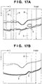
- a degree of difference between a plurality of intensity profiles associated with the A-scan direction may be used.
- the intensity profile indicates a graph showing the relationship between spatial positions in the A-scan direction and intensities at these positions, as indicated by the right view of Fig. 1A or 1B , and a difference between neighboring intensity profiles is normally small.
- the continuity may also be determined by combining the plurality of indices.
- step S620 an artifact generation side of the pair of layer candidate points determined as discontinuous points is checked to specify an edge portion of an artifact region.
- the artifact region edge portion specifying processing is executed for each pair of discontinuous layer candidate points. More specifically, in case of a pair of P i and P i+1 in Fig. 5 ,
- step S630 a layer candidate point on the artifact generation side is traced until a next discontinuous point is found to calculate a range of the artifact region. For example, a region until P i+3 is determined as an artifact region for P i+1 in Fig. 5 .
- step S640 an average, variance, or maximum value of intensities in a region on the positive direction side of the z-axis of the respective candidate point in the region determined as the artifact region is calculated.
- a spatial range in which the statistical amount associated with intensities is calculated is not limited to such specific range.
- an artifact region may be divided into arbitrary local regions, and the statistical amounts may be calculated for respective local regions.
- the layer candidate point tracing processing and calculation processing of the statistical amount associated with intensity signals need not always be executed as independent steps, and the statistical amount of intensity signals may be calculated every time layer candidate points are traced for an arbitrary range.
- artifact region determination processing may be executed not only for a B-scan image (a tomogram perpendicular to the y-axis) but also for a tomogram perpendicular to the x-axis, and an artifact region determined in both the determination processes may be determined as an artifact region.
- the determination processing may be three-dimensionally applied to a 3D tomogram.
- step S450 The sequence of the processing executed in step S450 will be described below with reference to Fig. 7 .
- step S710 the image correction unit 333 corrects intensities in each artifact region based on the statistical amount associated with the intensities in that artifact region calculated by the artifact region determination unit 332.
- the intensity correction method a method based on histogram conversion in the artifact region will be described. More specifically, the intensity average and variance in the artifact region are adjusted to be the same as those in a true image region.
- arbitrary image correction may be applied as long as it can establish a relationship of an increasing function between intensities before correction and those after correction in the artifact region.
- ⁇ and ⁇ are weights.
- the aforementioned image processing methods need not always be solely executed, but they may be executed in combination.
- the image correction may also be applied for respective local regions.
- step S720 the display unit 340 superimposes the correction result of the image in step S710 on the tomogram.
- boundaries of each artifact region are indicated by lines, lines of a predetermined color may be used for the respective boundaries, or a layer may be presented with a translucent color without explicitly indicating boundaries.
- Images before and after correction may be selectively displayed for a region designated using, for example, a GUI, and information of the statistical amount associated with intensities in each artifact region calculated in step S640 may be displayed. As described above, the processing in step S450 is executed.
- the image processing apparatus 10 specifies an artifact region, and executes image correction based on, for example, a statistical amount associated with intensity in that region, thus obtaining an image from which a layer included in the artifact region can be easily detected.
- FIG. 8 is a functional block diagram of the image processing apparatus 10 according to this explanatory example. Referring to Fig. 8 , an image processing unit 801 of this explanatory example is different from the arrangement of the image processing unit 330 of the image processing apparatus 10 of the first explanatory example in that a layer decision unit 334 is added.
- step S450 image processing in an artifact region is executed. Details of the processing of this step will be described below using Fig. 9 .
- an image correction unit 333 corrects intensities in an artifact region based on a statistical amount associated with the intensities in that region calculated by an artifact region determination unit 332. Note that this processing is the same as the image correction processing in step S710, and a detailed description thereof will not be given.
- the layer decision unit 334 acquires image features of a layer to be extracted based on intensity information of the region that has undergone the image correction by the image correction unit 333, and connects these feature points as a layer position.
- a retinal pigment epithelium is originally a highest-intensity region on each A-scan line, and tends to have higher intensities even in an artifact region.
- a layer position is decided by connecting, in an x-axis direction, pixels having maximum intensities located on the positive direction side of a z-axis of layer candidate points on respective A-scan lines of the image-corrected region.
- the method of detecting a layer from the image correction result is not limited to such specific method.
- a layer may be extracted by connecting pixels, which have intensities equal to or larger than a predetermined value on the positive direction side of the z-axis of layer candidate points, and have largest z-coordinates, on respective A-scan lines, in the x-axis direction.
- a layer may be extracted by calculating linear sums of intensities before and after image correction for respective pixels on respective A-scan lines of an artifact region, and connecting pixels corresponding to the maximum sum in the x-axis direction.
- a plurality of candidate points of a retinal pigment epithelium are selected on respective A-scan lines of an artifact region, and all the layer candidate points are defined as a layer candidate point set in the artifact region.
- a retina layer thickness is measured by calculating distances for respective x- and y-coordinates between the calculated layer candidate point sequence corresponding to the retinal pigment epithelium, and an inner limiting membrane 1 calculated in step S420.
- the measurement contents are not limited to this.
- an angle distribution between layer candidate points may be calculated so as to check an unevenness of a layer geometry.
- a layer thickness to be measured is not limited to the retina layer thickness.
- another layer geometry such as a photoreceptor cell layer may be analyzed.
- Information including the calculated layer thickness and layer geometry is output to a storage unit 320.
- step S1040 a display unit 340 superimposes, on the tomogram:
- the display unit 340 superimposes the layer decision result in step S1020 on the tomogram.
- boundaries of a layer are indicated by lines, lines of a predetermined color may be used for the respective boundaries, or a region of a layer may be presented with a translucent color without explicitly indicating boundaries.
- an arrangement that allows to select a section of interest using, for example, a GUI is desirably adopted.
- these results may be three-dimensionally displayed using a known volume rendering technique.
- the display unit 340 displays, as the layer geometry measurement result, a distribution map of the layer thicknesses for the entire 3D tomogram (x-y plane).
- the present invention is not limited to such specific display method, and areas of respective layers in a section of interest may be displayed, or a volume of the entire predetermined layer may be displayed. Alternatively, a volume in a region designated by an operator on an x-y plane may be calculated and displayed.
- step S1020 when the reliability of the detected layer is low (for example, when signals of the detected layer are weak) in step S1020, the layer is not detected, and the image correction result is superimposed on the tomogram.
- the present invention is not limited to such specific display method of the image correction result, and the image correction result may be displayed on the display unit 340 even when the layer detection result is satisfactory.
- step S450 As described above, the artifact region image processing in step S450 is executed. True image region image processing in step S455 will be described below.
- step S455 As the processing in a true image region,
- step S1030 in Fig. 9 .
- an analysis target is a non-corrected image unlike in step S1030.
- step S1040 in Fig. 10 , the display unit 340 displays the result.
- no image correction result is displayed unlike in step S1040.
- the image processing apparatus 10 executes image correction of a specified artifact region, and detects image features corresponding to a layer position from the correction result, thus calculating the layer position in the artifact region more precisely.
- a projection image is generated from a tomogram of an eye to be examined, and position information of tissue or a morbid portion extracted from the projection image is back-projected onto the tomogram, so as to narrow down artifact candidate regions in advance.
- position information of an artifact region caused by, for example, a blood vessel (or bleeding) from a projection image than from only a tomogram.
- this explanatory example will explain a case in which a blood vessel (bleeding) region is extracted from a projection image, that position information is mapped onto a tomogram, and an edge portion of an artifact region is searched for and specified around the mapped region, so as to calculate a range of the artifact region at higher precision.
- FIG. 10 is a functional block diagram of the image processing apparatus 10 according to this explanatory example.
- an image processing unit 1001 includes a projection image generation unit 335 and feature extraction unit 336 unlike in the image processing unit 330 of the image processing apparatus 10 of the first explanatory example. Since the remaining units are the same as those in Fig. 3 , a description thereof will not be repeated.
- the projection image generation unit 335 generates an image by projecting a tomogram. More specifically, a projection image is defined by pixel values as values obtained by simply adding intensities of pixels on the tomogram in a positive direction of a z-axis. However, each pixel value of the projection image is not limited to such value, and the sum of intensities may be divided by the number of added pixels. Alternatively, a maximum value or minimum value of intensities at each depth position may be used as each pixel value of the projection image. Also, intensities of all pixels in the z-axis direction need not be added, and those only in an arbitrary range or between specific layers may be added.
- a feature region where biological tissue such as a retina blood vessel in an eye to be examined or a morbid portion exists is extracted from the projection image generated by the projection image generation unit 335. Since the retina blood vessel has a thin linear structure, it is extracted using a filter that emphasizes the linear structure.
- a line segment emphasizing filter based on a contrast for example, a filter which calculates a difference between an average value of image density values in a line segment defined as a structural element, and an average value in a local region that surrounds the structural element, is used.
- a multi-valued region obtained as the processing result of the filter may be used as a blood vessel extraction result, or a region binarized using a certain threshold may be used as the extraction result.
- the method of emphasizing the linear structure is not limited to this.
- a differential filter such as a Sobel filter or Laplacian filter may be used.
- Eigenvalues of a Hessian matrix may be calculated for respective pixels of a density value image, and a linear region may be extracted from combinations of two eigenvalues obtained as results.
- an arbitrary known blood vessel extraction method such as tophat operations simply using a line segment as a structural element may be used.
- a back-projection region is obtained, as indicated by a dotted region 8 in Fig. 12 .
- intensity attenuation readily occurs on the positive direction side of the z-axis of the retina blood vessel. Therefore, when the position (in x-y directions) of the extracted feature is back-projected onto the tomogram, the back-projected dotted region 8 is more likely to include an artifact region 5.
- no intensity attenuation occurs in the back-projection region. Even when a correctly extracted retina blood vessel region is back-projected, intensity attenuation below the back-projection region is slight and has nearly no influence on layer extraction in some cases.
- step S430 is basically the same as that in steps S610 to S640 of the first embodiment, except for a range of layer candidate points as calculation targets of a continuity. More specifically, the continuity calculation processing is executed not for all layer candidate points, but for the interior of the back-projection region and in the vicinity of the region in x-y directions.
- the image processing apparatus 10 of this explanatory example specifies an artifact region from a tomogram and projection image, and executes image correction based on, for example, an intensity statistical amount in that region, thus obtaining an image from which a layer region included in the artifact region can be detected more easily.
- this explanatory example not only executes image correction in an artifact region after the artifact region is determined, but also detects a predetermined layer from the corrected image.
- This explanatory example copes with the following points.
- Fig. 13 is a functional block diagram of the image processing apparatus 10 according to this explanatory example.
- An image processing unit 1301 of this explanatory example includes a layer decision unit 334 unlike in the image processing unit 1001 of the third explanatory example.
- the contents of image processing of this explanatory example are the same as those in Fig. 13 , except for processes in steps S450 and S455. Hence, only the processes in step S450 and S455 of this explanatory example will be explained, and a description of other steps will not be given.
- step S450 as image processing in an artifact region, image correction, layer decision, layer geometry measurement, and result display processes are executed.
- the processing of this step is the same as that in steps S1010 to S1040 in the second explanatory example , and a detailed description thereof will not be repeated.
- step S455 as processing executed when no artifact is generated, a layer geometry is measured from a layer position acquired in step S420, and the layer position and layer geometry measurement result are superimposed on a tomogram. Details of the superimposing method are the same as those in steps S1110 to S1120 in the second explanatory example , and a detailed description thereof will not be repeated.
- the image processing apparatus 10 of this explanatory example specifies an artifact region from a tomogram and projection image, and executes image correction in that region. Since the apparatus detects image features of a layer from the correction result, the layer position in that region can be calculated more precisely.
- position information of tissue or a morbid portion extracted from at least one of a surface image of an eye to be examined and a projection image is back-projected onto a tomogram to narrow down artifact candidate regions in advance, in addition to the third explanatory example.
- a morbid portion such as an exudate, which is especially easily extracted from a surface image
- an exudate region is calculated using a surface image, and an edge portion of an artifact region is searched for and specified from a surrounding region of the extracted morbid portion, thus allowing to calculate a range of an artifact region with higher precision.
- Fig. 14 shows the arrangement of apparatus connected to an image processing apparatus 10 according to this explanatory example.
- the arrangement includes a surface image capturing apparatus 50 in addition to a tomography apparatus 20 unlike in the third explanatory example.
- the surface image capturing apparatus 50 captures a surface image of an eye portion, and includes, for example, a fundus camera or SLO (Scanning Laser Ophthalmoscope).
- Fig. 15 is a functional block diagram of the image processing apparatus 10 of this explanatory example.
- the image processing apparatus 10 of this explanatory example includes a surface image acquisition unit 315, and an image processing unit 1501 includes a registration unit 337 unlike in the arrangement of the image processing apparatus 10 of the third explanatory example.
- Image processing in the image processing unit 1501 of this explanatory example will be described below with reference to the flowchart shown in Fig. 16 .
- the image processing sequence of this explanatory example is nearly the same as that shown in Fig. 11 , except for processes in steps S1610 to S1650. Hence, the processes in these steps will be described below.
- step S1610 in addition to acquisition of a tomogram by a tomogram acquisition unit 310, the surface image acquisition unit 315 requests the surface image capturing apparatus 50 to transmit a surface image, and acquires a surface image transmitted from the surface image capturing apparatus 50. Assume that a fundus camera image is input as the surface image. The unit 315 transmits the acquired information to a storage unit 320.
- step S1620 that follows projection image generation processing in step S1110, the feature extraction unit 336 extracts tissue such as a blood vessel or a morbid region such as an exudate from the surface image acquired by the surface image acquisition unit 315. Since a retina blood vessel has a linear structure, it is extracted using a filter that emphasizes the linear structure. Since the linear structure extraction method is the same as that in step S1120, a description thereof will not be given. Since an exudate exists as a granular high-intensity region, it is calculated by morphology operations such as tophat transformation.
- an exudate region is obtained as a high-intensity multi-valued region by the morphology operations, and the multi-valued region itself may be used as an extraction result or a region binarized using a certain threshold may be used as the extraction result.
- the exudate extraction method is not limited to this, and an exudate may be identified by an identifier such as a Support Vector Machine or an identifier ensemble such as Ada Boost using intensities of the surface image and an output result of a known filter which emphasizes a contrast as feature amounts.
- the registration unit 337 performs registration between the projection image and surface image so as to associate the coordinates of the projection image with those of the surface image.
- an evaluation function which represents a similarity between two images, is defined in advance, and images are deformed to obtain the best evaluation value.
- the similarity evaluation method a method of evaluating a similarity based on pixel values using a mutual information content is used.
- the present invention is not limited to such specific method, and a mean square error, correlation coefficients, or an overlapping area of blood vessel regions, distances between branch portions of blood vessels, or the like, which are extracted from the surface image and projection image by the feature extraction unit 336, may be used.
- Image deformation is implemented by translating or rotating images or changing an enlargement factor under the assumption of affine transformation.
- step S1640 the blood vessel or exudate extraction result from the surface image calculated in step S1620 is back-projected onto a tomogram using registration parameters calculated in step S1630.
- a back-projection region regions indicated by dotted regions 8 in Fig. 17A are obtained.
- each back-projected dotted region 8 is more likely to include an artifact.
- the artifact region determination method is basically the same as that in case of steps S610 to S640 of the first explanatory example , but a range of layer candidate points as calculation targets of a continuity is different from the first explanatory example. More specifically, the continuity calculation processing is executed not for all layer candidate points, but for the interior of the back-projection region and in the vicinity of the region in x-y directions.
- the artifact region may be determined with reference to information obtained from the projection image and a fundus image in addition to that obtained from only the tomogram. For example, when a retina blood vessel region obtained from the projection image overlaps that obtained from the fundus image, it may be considered that the region is more likely to be a blood vessel, and an edge portion of that region may be determined to be discontinuous.
- a linear sum of a continuity value calculated from the tomogram and a value of a degree of overlapping of the blood vessel regions may be calculated, and may be binarized using a threshold, so as to determine a continuity.
- artifact region image processing in step S1650 displays a correction result after image correction, that is, it adopts basically the same sequence as in the first explanatory example , a detailed description thereof will not be given.
- information obtained from the fundus image may also be referred to.
- intensities of an exudate are very high on the fundus image, since intensities are more likely to be attenuated on the positive direction side of the z-axis of layer candidate points even on the tomogram, intensities are amplified or emphasized in proportion to intensity signal values of an exudate region.
- intensities of an exudate region pixel values of that region on the fundus image are directly referred to.
- intensities of the exudate region are not limited to these values, and values (multi-valued data) of the processing result obtained by, for example, morphology operations or the like may be referred to.
- the image processing apparatus 10 of this explanatory example executes image correction based on a statistical amount of intensities in an artifact region specified using a surface image and projection image, thereby obtaining an image from which a layer region that exists in the region can be detected more easily.
- This explanatory example not only executes image correction of an artifact region in the fifth explanatory example , but also detects a predetermined layer from the corrected image. Especially when an artifact is generated due to an exudate, this explanatory example uses the following points.
- Fig. 18 is a functional block diagram of the image processing apparatus 10 according to this explanatory example.
- An image processing unit 1801 of this explanatory example includes a layer decision unit 334 unlike in the image processing unit 1501 of the fifth explanatory example.
- the image processing sequence of this explanatory example is the same as that shown in Fig. 16 except for processes in steps S1650 and S455. Hence, only the processes in steps S1650 and S455 will be explained, and a description of other steps will not be repeated.
- step S1650 as image processing in an artifact region, image correction, layer decision, layer geometry measurement, and result display processes are executed.
- the processing of this step is the same as that in steps S1010 to S1040 in the second explanatory example , and a detailed description thereof will not be repeated.
- image correction can be executed also using information obtained from a fundus image in step S1010.
- a practical sequence for referring to information obtained from a fundus image at the time of image correction is the same as that in case of step S1650 in the fifth explanatory example , and a description thereof will not be repeated.
- step S455 as processing to be executed when no artifact is generated, a layer geometry is measured from a layer position acquired in step S420, and the layer position and the layer geometry measurement result are superimposed on the tomogram.
- the superimposing method in this case is the same as that in the second explanatory example , and a detailed description thereof will not be repeated.
- the image processing apparatus 10 executes image correction in an artifact region specified from a surface image and projection image. By detecting image features of a layer from the correction result, the layer position in the region can be calculated more precisely.
- an artifact region is determined from a tomogram of an eye to be examined, and a layer position in the artifact region is calculated using both pieces of information in consideration of intensities in the artifact region and a layer geometry around the region.
- FIG. 19 is a functional block diagram of the image processing apparatus 10 according to this explanatory example.
- an image processing unit 1901 of this explanatory example includes an image processing method decision unit 1910 in place of the image correction unit 333, and additionally includes a layer decision unit 334 unlike in the arrangement of the image processing unit 330 of the image processing apparatus 10 of the first explanatory example.
- the image processing method decision unit 1910 includes a intensity use judgment unit 1911 and evaluation function setting unit 1912. The functions of respective blocks, which configure the image processing apparatus 10, will be described below with reference to the flowchart shown in Fig. 20 in association with the practical processing sequence to be executed by the image processing apparatus 10 of this explanatory example.
- an artifact region determination unit 332 branches processes according to a determination result obtained in step S430. That is, for a layer candidate point for which it is determined that an artifact is generated, the unit 332 transmits a signal to instruct the image processing method decision unit 1910 to execute predetermined processing. On the other hand, if the unit 332 determines a true image region where no artifact is generated, it transmits a signal to instruct a display unit 340 to execute predetermined processing.
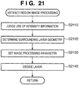
- step S2020 the image processing unit 1901 executes analysis processing when an artifact is generated near candidate points of a predetermined layer.
- the processing of this step will be described in detail later using the flowchart shown in Fig. 21 .
- step S2030 the display unit 340 superimposes a layer determination result on a tomogram.
- lines of a predetermined color may be used for the respective boundaries, or a region of a layer may be presented with a translucent color without explicitly indicating boundaries.
- an arrangement that allows to select a section of interest using, for example, a GUI is desirably adopted.
- these results may be three-dimensionally displayed using a known volume rendering technique.
- a retina layer thickness can be measured by calculating distances for respective coordinates (x, y) between a calculated layer candidate point sequence corresponding to a retinal pigment epithelium, and an inner limiting membrane 1 calculated in step S420.
- the display unit 340 presents information associated with the measured layer geometry as a distribution map of layer thicknesses with respect to an entire 3D tomogram (x-y plane).
- the display unit 340 may display areas of respective layers in a section of interest in synchronism with the display process of the detection result.
- the display unit 340 may display an entire volume or may calculate and display a volume in a region which is designated by an operator on the x-y plane.
- step S2020 of this explanatory example a Deformable Model is applied to a layer position so that the layer position can be calculated even in a tomogram including noise.
- An example using Snakes as a Deformable Model will be described below.
- the layer position is decided by minimizing a linear sum of evaluation function values associated with a model geometry and those associated with intensities near control points which configure the model.
- evaluation functions associated with a geometry linear sums of differences and secondary differential values of control point positions which configure a model are used.
- the model geometry becomes smoother with decreasing linear sums.
- evaluation functions associated with intensity values obtained by assigning the negative sign to intensity gradients near control points that configure a model are used. This is to reduce evaluation function values with decreasing distance to an edge.
- Weights of evaluation functions used to deform a Deformable Model are normally set to be fixed values irrespective of whether or not control points that configure the model are included in an artifact region. In this case, since intensities in the artifact region are attenuated, and a change in intensity is small in that region, a layer position is practically decided based on the magnitudes of the evaluation function values associated with the model geometry.
- the layer position is to be decided while placing importance on information associated with intensity (in preference to a case in which the layer position is calculated based on a smoothness of the model geometry), thereby detecting the layer geometry more precisely. For this reason, weights of the evaluation functions associated with intensity are set to be larger than those for a true image region according to the degree of attenuation of intensities at control points in the artifact region.
- intensity information of, for example, an edge cannot be used at the time of decision of the layer position.
- the weights of the evaluation functions associated with intensity are not increased, and the layer position is to be decided based on the magnitudes of the function evaluation values associated with the model geometry.
- step S2110 the image processing method decision unit 1910 reads out, from a storage unit 320, a statistical amount associated with intensities in an artifact region, which is calculated in step S640 of the flowchart of Fig. 6 , that shows details of the artifact region determination processing in step S430.
- the unit 1910 judges based on the statistical amount whether intensity information is used at the time of layer detection since an (attenuated) edge remains in that region or intensity information of, for example, an edge is not used since intensity is deficient.
- i a control point number of the Deformable Model
- B is a statistical amount associated with intensities in a background region (for example, a region on the negative direction side of a z-axis of the inner limiting membrane 1)
- Fi is a statistical amount associated with intensities in an artifact region to which a control point i belongs.
- T s is a threshold.
- the statistical amount associated with intensities is not limited to this. For example, an average value, variance, or standard deviation may be used. Also, the artifact region may be divided into arbitrary local regions, and statistical amounts of intensities in local regions to which respective control points belong may be used as Fi.
- step S2120 the image processing method decision unit 1910 acquires information associated with an unevenness of a layer candidate point sequence around the artifact region. This is because if a layer geometry around the artifact region has an unevenness, an unevenness is likely to be also generated in the region, and the layer position has to be calculated by lowering weights associated with evaluation of smoothness of the geometry. As a method of calculating a practical unevenness of the layer geometry, a statistical amount associated with angles between layer candidate points around the artifact region is calculated. In this case, a maximum value is used as the statistical amount.
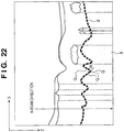
- An angle between layer candidate points at a layer candidate point i is calculated as an angle ⁇ i between a line segment obtained by extending a line segment Q i-1 -Q i to the Q i+1 side, and a line segment Q i -Q i+1 , as shown in Fig. 22 .
- the unevenness is larger with increasing ⁇ i .
- Such angle calculation is executed for respective layer candidate points around the artifact region, and a maximum value of the calculated angles is used as an index which represents a degree of unevenness of the layer candidate point sequence.
- the index associated with the degree of unevenness is not limited to the angle between layer candidate points, and a statistical amount (an average, variance, maximum value, etc.) of secondary differential values (Q i-1 - 2Q i + Q i+1 ) at the layer candidate point positions may be calculated. Alternatively, an extremum or the number of inflection points when the layer candidate around the artifact region is regarded as a curve may be calculated.
- the statistical amount associated with the degree of unevenness of the layer candidate points is not limited to the maximum value. For example, an average value, variance, or standard deviation may be used.
- step S2130 the image processing method decision unit 1910 sets weights of the evaluation functions of the Deformable Model using the judgment result in step S2110 and the index associated with the degree of unevenness of the layer geometry calculated in step S2120.
- weights of the evaluation functions associated with the geometry values, which are inversely proportional to the index representing the degree of unevenness of a layer geometric model calculated in step S2120, are set.
- the weights of the evaluation functions associated with intensities are set as follows according to the judgment result associated with use of intensity information in the artifact region calculated in step S2110.
- the weights of the evaluation functions associated with intensity are increased in accordance with degrees of attenuation of intensities in the artifact region. Then, values proportional to a ratio T s /F s between a intensity statistical amount F s in the region calculated in step S640 and a intensity statistical amount T s in a true image region are set as the weights of the evaluation functions associated with intensity.
- the setting method of the weights of the evaluation functions associated with intensity is not limited to this. For example, an arbitrary weight function may be set as long as a relationship of a decreasing function is established between F s and the weights of the evaluation functions associated with intensity.
- the weights of the evaluation functions associated with intensities of a geometric model are set to be the same values as those of a true image region.
- the setting method of the weights of the evaluation functions associated with intensities in (ii) is not limited to this.
- the weights of the evaluation functions associated with intensities may be reduced or may be set to be zero.
- the layer decision unit 334 calculates evaluation values according to the weights of the evaluation functions set in step S2130, and makes iterative calculations using an optimization method such as a Greedy Algorithm, thus minimizing the evaluation function values.
- the unit 334 ends deformation of the layer geometric model, and decides the position of the layer geometric model at the end timing as a layer position.
- these geometric models may be calculated as either 2D or 3D curve models.
- This embodiment has explained the example using Snakes as a Deformable Model, but Level Set may be used.
- arbitrary methods may be used as long as they set the weights of evaluation functions associated with intensities in a model-based segmentation method which refers to intensities upon deformation of a model.
- the image processing apparatus 10 specifies an artifact region, and executes image processing in consideration of an unevenness of a layer geometry around the region and edge information in the region, thus calculating a layer position with higher precision than the conventional method.
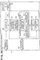
- FIG. 23 is a functional block diagram of the image processing apparatus 10 according to this explanatory example.
- an image processing unit 2301 includes an image correction unit 333
- an image processing method decision unit 1910 includes an image correction method setting unit 1913 and interpolation function setting unit 1914 unlike in the seventh explanatory example.
- step S2410 It is judged in step S2410 whether intensity information is used upon calculating a layer position since a weak edge remains in an artifact region or intensity information of, for example, an edge is not used since intensity is deficient. Since the practical judgment sequence is the same as that in step S2110 of the seventh embodiment, a description thereof will not be repeated.
- a intensity use judgment unit 1911 branches processes according to the judgment result in step S2410. That is, if it is judged that intensity information in the artifact region is used upon deciding a layer position, the unit 1911 transmits a signal which instructs the image correction method setting unit 1913 to execute predetermined processing. On the other hand, if it is judged that intensity information in the region is not used, the unit 1911 transmits a signal which instructs the interpolation function setting unit 1914 to execute predetermined processing.
- step S2430 parameters required to execute conversion (image correction) of intensities in the artifact region are set.
- image correction Various image correction methods are available. In this explanatory example, setting sequences of parameters in the following image correction methods will be explained.
- image correction which adjusts the maximum intensity in the artifact region to that in the true image region is executed.
- a smoothing parameter s based on a Gaussian function which is executed as preprocessing of the layer structure emphasizing processing, is set as follows.
- image correction methods in this embodiment are not limited to these methods.
- arbitrary image correction methods may be used as long as a relationship of an increasing function is established between intensities before and after correction in the artifact region is established, and they include adjustable parameters.
- step S2440 the image correction unit 333 executes conversion (image correction) of intensities in the artifact region based on the image correction method set in step S2430, thus facilitating detection of the layer position.
- step S2450 the layer decision unit 334 acquires image features of a layer to be extracted based on intensity information of the region which has undergone the image correction by the image correction unit 333, and defines a layer position by connecting these feature points.
- a retinal pigment epithelium is originally a highest-intensity region on respective A-scan lines, and tends to have higher intensities even in the artifact region.
- the layer position is decided by connecting maximum intensity pixels located on the positive direction side of the z-axis of layer candidate points on respective A-scan lines in the image-corrected region in the x-axis direction.
- the layer position when the intensity use judgment unit 1911 judges that intensity information in the artifact region is used is decided.
- the processing contents of the image processing method decision unit 1910 when the intensity use judgment unit 1911 judges that intensity information in an artifact region is not used will be described below.
- step S2460 the image processing method decision unit 1910 acquires information associated with a range of an artifact region calculated by an artifact region determination unit 332. More specifically, letting i be a label of an artifact region in Fig. 25 , the unit 1910 acquires information associated with a generation position (x i , y i ) and width W i of an artifact, and the number d i of layer candidate points which belong to a true image region n i near the region. In step S2470, the unit 1910 calculates an index which represents a degree of unevenness of a layer candidate point sequence, which exists around the artifact region. Since such index is the same as that calculated in step S2120, a detailed description thereof will not be repeated.
- step S2480 the image processing method decision unit 1910 selects a type or order of an interpolation function used upon interpolating layer candidate point sequences between artifact regions, and layer candidate points used in interpolation from the information acquired in steps S2460 and S2470.
- layer candidate points are selected as follows. That is, the direction to be interpolated is changed to a direction in which layer candidate points that can be used in interpolation sufficiently exist, and layer candidate points which belong to true image regions near that direction are selected. For example, when an artifact region exists at the edge of an image, as shown in Fig. 25 , and the number of layer candidate points used in interpolation in association with an x-direction is short, layer candidate points in true image regions, which exist near the artifact region on a y-z plane that passes through the artifact region, can be selected.
- the type of direction to be interpolated is not always limited to a direction parallel to the x- or y-axis, and it may be changed to an arbitrary direction in which layer candidate points that can be used in interpolation sufficiently exist.
- layer candidate points in true image regions which exist near an artifact region on a plane generated by circular scan like in Fig. 25 , may be selected.
- Information associated with the image processing method decided in this step is transmitted to the layer decision unit 334.
- step S2450 the layer decision unit 334 decides the layer position in the artifact region by interpolating between layer candidate points selected in step S2480 by the interpolation function of the type selected in that step. Then, information of the calculated layer position is output to a storage unit 320.
- the artifact region image processing corresponding to this explanatory example is executed.
- image correction is executed after the image processing method is decided.
- the image correction execution timing is not limited to this.
- the image correction unit 333 may execute image correction according to the degree of intensity attenuation in the region.
- the image processing method decision unit receives the image correction result, and makes settings associated with interpolation processing in response to the judgment result by the intensity use judgment unit.
- the image correction method setting unit 1913 is included in the image correction unit 333.
- the image processing apparatus 10 specifies an artifact region, and judges whether or not to use intensity information of, for example, an edge in the artifact region. If intensity information of, for example, an edge is used, the layer decision processing is executed after intensities in the region are corrected. When the information is not used, interpolation processing is executed according to a range of the artifact region and the layer geometry around the region, thus calculating a layer position with high precision.
- a projection image is generated from a tomogram of an eye to be examined, and position information of tissue or a morbid portion extracted from the projection image is back-projected onto the tomogram to narrow down artifact candidate regions, in place of calculating a layer position in an artifact region using only a tomogram in the seventh embodiment.
- This embodiment covers the following points.
- Fig. 26 is a functional block diagram of the image processing apparatus 10 according to this embodiment.
- An image processing unit 2601 of this embodiment includes a projection image generation unit 335 and feature extraction unit 336 unlike in the image processing unit 1901 shown in Fig. 19 of the seventh explanatory example. Since the remaining units are the same as those in Fig. 19 , a description thereof will not be repeated.
- step S2710 the projection image generation unit 335 generates an image by projecting a tomogram. Since a practical generation method is the same as that described in step S1110 in Fig. 11 of the third explanatory example, a description thereof will not be repeated.
- step S2720 features of tissue such as a retina blood vessel or a morbid portion are extracted from the projection image generated by the projection image generation unit 335. Since a practical generation method is the same as that described in step S1120 in Fig. 11 of the third explanatory example, a description thereof will not be repeated.
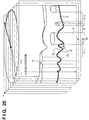
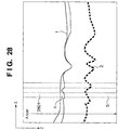
- step S2730 when a blood vessel region (x, y) on the projection image calculated in step S2720 is back-projected onto the tomogram, a region indicated by a dotted region 2801 in Fig. 28 (to be referred to as a back-projection region hereinafter) is obtained.
- a back-projection region In general, on the positive direction side of a z-axis of a retina blood vessel, attenuation of intensities readily occurs. Therefore, when the position (in x-y directions) of the extracted feature is back-projected onto the tomogram, the back-projected dotted region 2801 is more likely to include an artifact region 5.
- the artifact region determination method is basically the same as that in steps S610 to S640 of the first explanatory example, except for a range of layer candidate points as calculation targets of a continuity. More specifically, the continuity calculation processing is executed not for all layer candidate points, but for the interior of the back-projection region and in the vicinity of the region in x-y directions.
- an artifact region is specified using a tomogram and projection image, and a layer model is applied by weighting evaluation functions in consideration of not only a layer geometry around the region but also edge information in the region, thus calculating a layer position with high precision.
- This explanatory example executes image correction of an artifact region and then calculates a layer position when intensity information of, for example, an edge is used after judgment of a intensity use judgment unit, and calculates a layer position by interpolation processing when the information is not used, in the embodiment.
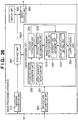
- Fig. 29 is a functional block diagram of the image processing apparatus 10 according to this explanatory example.
- An image processing unit 2901 of this explanatory example further includes a registration unit 337, and an image processing method decision unit 1910 includes an image correction method setting unit 1913 and interpolation function setting unit 1914 in place of the evaluation function setting unit 1912 unlike in the embodiment.
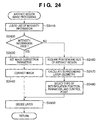
- the contents of image processing of this explanatory example will be described below with reference to the image processing sequences shown in Figs. 24 and 27 .
- steps other than step S2020 are the same as those in the embodiment. Hence, the process in step S2020 will be described below, and a description of other steps will not be repeated.
- step S2020 image processing in an artifact region is executed. Since the processing in this step is the same as that in steps S2410 to S2480 of Fig. 24 in the eighth explanatory example, a detailed description thereof will not be repeated.
- the image processing apparatus 10 specifies an artifact region using a tomogram and projection image, and judges whether or not to use intensity information of, for example, an edge in the region.
- layer determination processing is executed after intensities in the region are corrected.
- interpolation processing is executed according to a range of the artifact region and the layer geometry around the region, thus calculating a layer position with high precision.
- This explanatory example adds, to the embodiment, processing for back-projecting, onto a tomogram, position information of tissue or a morbid portion extracted from at least one of a surface image of an eye to be examined and a projection image so as to narrow down artifact candidate regions in advance.
- the arrangement of apparatus connected to an image processing apparatus 10 according to this explanatory example additionally includes a surface image capturing apparatus 50, as shown in Fig. 14 , unlike in the embodiment.
- an image processing unit 3001 includes a surface image acquisition unit 315, as shown in Fig. 30 , unlike in the embodiment.
- step S3150 image processing in an artifact region is executed.
- the processing in this step is basically the same as that in steps S2110 to S2140 of the seventh explanatory example.
- image processing parameters may be set also using information obtained from a fundus image. For example, when intensities of an exudate are very high on a fundus image, since intensities are more likely to be attenuated on the positive direction side of a z-axis of an exudate region also on a tomogram, weights of evaluation functions associated with a geometry are increased in proportion to intensity signal values of the exudate region.
- intensity signal values of the exudate region pixel values of that region on the fundus image may be directly referred to, or values (multi-valued data) of a region obtained as the processing result of morphology operations or the like may be referred to.
- This explanatory example executes image correction of an artifact region and then decides a layer position when intensity information of, for example, an edge is used after judgment of a intensity use judgment unit, and calculates a layer position by interpolation processing when the information is not used, in the 10th explanatory example.
- Fig. 32 is a functional block diagram of the image processing apparatus 10 according to this explanatory example.
- an image processing method decision unit 1910 includes an image correction method setting unit 1913 and interpolation function setting unit 1914 in place of the evaluation function setting unit 1912 unlike in the fifth explanatory example.
- the image processing sequence in this embodiment is basically the same as that in the 10th explanatory example.
- the processing in step S3150 is executed as follows.
- step S3150 has the same sequence as in the ninth explanatory example. That is, whether or not to use intensity information of, for example, an edge in an artifact region is judged, as shown in Fig. 24 .
- layer decision processing is executed after intensities in the region are corrected.
- a type of an interpolation function and parameters are set according to a range of the region and the layer geometry around the region, and interpolation processing is then executed.
- an artifact region specified using a surface image and projection image whether or not to use intensity information of, for example, an edge in that region is judged.
- layer decision processing is executed after intensities in the region are corrected.
- interpolation processing is executed according to a range of the artifact region and the layer geometry around the region. In this way, a layer position can be calculated with high precision.
- an embodiment of the present invention implements the present invention as an image processing apparatus.
- an embodiment of the present invention is not limited to only the image processing apparatus, but may be implemented as software which implements functions when it is executed by a CPU of a computer.
- Fig. 33 is a block diagram showing the basic arrangement of a computer used to implement the functions of respective units of an image processing apparatus 10 as software.
- a CPU 3301 controls the overall computer using programs and data stored in a RAM 3302 and ROM 3303. Also, the CPU 3301 implements the functions of the respective units by controlling execution of software programs corresponding to the respective units of the image processing apparatus 10.
- the RAM 3302 includes an area for temporarily storing computer programs and data loaded from an external storage device 3304, and also a work area required for the CPU 3301 to execute various processes.
- the function of a storage unit 320 is implemented by the RAM 3302.
- the ROM 3303 generally stores a BIOS, setting data, and the like of the computer.
- the external storage device 3304 serves as a large-capacity information storage device such as a hard disk drive, and stores an operating system and programs executed by the CPU 3301.
- the external storage device 3304 stores information which is given in the description of this embodiment, and such information is loaded onto the RAM 3302 as needed.
- a monitor 3305 is configured by, for example, a liquid crystal display.
- the monitor 3305 can display the contents output from a display unit 340.
- a keyboard 3306 and mouse 3307 are input devices. An operator can input various instructions to the image processing apparatus 10 using these input devices.
- An interface 3308 is used to exchange various data between the image processing apparatus 10 and external apparatus, and is configured by, for example, an IEEE1394, USB, or Ethernet® port. Data acquired via the interface 3308 is fetched onto the RAM 3302. Functions of a tomogram acquisition unit 310 and result output unit 350 are implemented via the interface 3308. The aforementioned components are interconnected via a bus 3309.
- aspects of the present invention can also be realized by a computer of a system or apparatus (or devices such as a CPU or MPU) that reads out and executes a program recorded on a memory device to perform the functions of the above-described embodiment(s), and by a method, the steps of which are performed by a computer of a system or apparatus by, for example, reading out and executing a program recorded on a memory device to perform the functions of the above-described embodiment(s).
- the program is provided to the computer for example via a network or from a recording medium of various types serving as the memory device (for example, computer-readable medium).
Landscapes
- Health & Medical Sciences (AREA)
- Life Sciences & Earth Sciences (AREA)
- Engineering & Computer Science (AREA)
- Physics & Mathematics (AREA)
- General Health & Medical Sciences (AREA)
- Biomedical Technology (AREA)
- Biophysics (AREA)
- Radiology & Medical Imaging (AREA)
- Heart & Thoracic Surgery (AREA)
- Medical Informatics (AREA)
- Molecular Biology (AREA)
- Surgery (AREA)
- Animal Behavior & Ethology (AREA)
- Nuclear Medicine, Radiotherapy & Molecular Imaging (AREA)
- Public Health (AREA)
- Veterinary Medicine (AREA)
- General Physics & Mathematics (AREA)
- Ophthalmology & Optometry (AREA)
- Pathology (AREA)
- Theoretical Computer Science (AREA)
- Computer Vision & Pattern Recognition (AREA)
- Signal Processing (AREA)
- Eye Examination Apparatus (AREA)
- Image Analysis (AREA)
- Image Processing (AREA)
Applications Claiming Priority (2)
| Application Number | Priority Date | Filing Date | Title |
|---|---|---|---|
| JP2009133455A JP4909378B2 (ja) | 2009-06-02 | 2009-06-02 | 画像処理装置及びその制御方法、コンピュータプログラム |
| PCT/JP2010/059302 WO2010140601A1 (en) | 2009-06-02 | 2010-05-26 | Image processing apparatus, control method thereof, and computer program |
Publications (3)
| Publication Number | Publication Date |
|---|---|
| EP2437648A1 EP2437648A1 (en) | 2012-04-11 |
| EP2437648A4 EP2437648A4 (en) | 2014-09-17 |
| EP2437648B1 true EP2437648B1 (en) | 2019-09-11 |
Family
ID=43297734
Family Applications (1)
| Application Number | Title | Priority Date | Filing Date |
|---|---|---|---|
| EP10783383.2A Active EP2437648B1 (en) | 2009-06-02 | 2010-05-26 | Image processing apparatus, control method thereof, and computer program |
Country Status (6)
| Country | Link |
|---|---|
| US (1) | US8861817B2 (ja) |
| EP (1) | EP2437648B1 (ja) |
| JP (1) | JP4909378B2 (ja) |
| KR (1) | KR101318685B1 (ja) |
| CN (1) | CN102458221B (ja) |
| WO (1) | WO2010140601A1 (ja) |
Families Citing this family (68)
| Publication number | Priority date | Publication date | Assignee | Title |
|---|---|---|---|---|
| JP4850927B2 (ja) * | 2009-06-02 | 2012-01-11 | キヤノン株式会社 | 画像処理装置、画像処理方法及びコンピュータプログラム |
| JP5436076B2 (ja) | 2009-07-14 | 2014-03-05 | キヤノン株式会社 | 画像処理装置、画像処理方法およびプログラム |
| JP5645432B2 (ja) * | 2010-03-19 | 2014-12-24 | キヤノン株式会社 | 画像処理装置、画像処理システム、画像処理方法、及び画像処理をコンピュータに実行させるためのプログラム |
| JP5657941B2 (ja) * | 2010-07-30 | 2015-01-21 | 株式会社トプコン | 光断層画像化装置及びその作動方法 |
| EP2609853A4 (en) * | 2010-08-27 | 2016-03-09 | Sony Corp | APPARATUS AND METHOD FOR IMAGE PROCESSING |
| JP5702991B2 (ja) | 2010-11-19 | 2015-04-15 | キヤノン株式会社 | 画像処理装置及び画像処理方法 |
| JP5701024B2 (ja) * | 2010-11-26 | 2015-04-15 | キヤノン株式会社 | 画像処理装置及び方法 |
| JP5242667B2 (ja) | 2010-12-22 | 2013-07-24 | 株式会社東芝 | マップ変換方法、マップ変換装置及びマップ変換プログラム |
| JP5904711B2 (ja) | 2011-02-01 | 2016-04-20 | キヤノン株式会社 | 画像処理装置、画像処理方法およびプログラム |
| CN102136135B (zh) * | 2011-03-16 | 2012-12-19 | 清华大学 | 眼前节光学相干层析图像的角膜及眼前房内轮廓提取方法 |
| JP5836634B2 (ja) | 2011-05-10 | 2015-12-24 | キヤノン株式会社 | 画像処理装置及び方法 |
| JP6025311B2 (ja) | 2011-08-01 | 2016-11-16 | キヤノン株式会社 | 眼科診断支援装置および方法 |
| JP5955163B2 (ja) | 2011-09-06 | 2016-07-20 | キヤノン株式会社 | 画像処理装置および画像処理方法 |
| JP5912358B2 (ja) * | 2011-09-14 | 2016-04-27 | 株式会社トプコン | 眼底観察装置 |
| US8864309B2 (en) | 2011-12-05 | 2014-10-21 | Bioptigen, Inc. | Optical imaging systems having input beam shape control and path length control |
| JP6101048B2 (ja) | 2012-02-20 | 2017-03-22 | キヤノン株式会社 | 画像処理装置及び画像処理方法 |
| JP5947561B2 (ja) | 2012-02-20 | 2016-07-06 | キヤノン株式会社 | 画像形成装置及び画像形成方法 |
| JP6114495B2 (ja) | 2012-02-20 | 2017-04-12 | キヤノン株式会社 | 画像表示装置及び画像表示方法、撮影システム |
| JP5979904B2 (ja) * | 2012-02-20 | 2016-08-31 | キヤノン株式会社 | 画像処理装置、眼科撮影システム、及び画像処理方法 |
| US8777412B2 (en) | 2012-04-05 | 2014-07-15 | Bioptigen, Inc. | Surgical microscopes using optical coherence tomography and related methods |
| JP2014045869A (ja) * | 2012-08-30 | 2014-03-17 | Canon Inc | 撮影装置、画像処理装置、及び画像処理方法 |
| JP6099903B2 (ja) * | 2012-08-30 | 2017-03-22 | キヤノン株式会社 | 画像処理装置および画像処理方法 |
| JP6075844B2 (ja) * | 2012-10-18 | 2017-02-08 | キヤノン株式会社 | 眼科装置および眼科方法並びに記憶媒体 |
| JP2014110883A (ja) * | 2012-10-30 | 2014-06-19 | Canon Inc | 画像処理装置及び画像処理方法 |
| GB201302887D0 (en) * | 2013-02-19 | 2013-04-03 | Optos Plc | Improvements in or relating to image processing |
| JP6092659B2 (ja) | 2013-02-28 | 2017-03-08 | キヤノン株式会社 | 画像処理装置及び画像処理方法 |
| JP6198410B2 (ja) | 2013-02-28 | 2017-09-20 | キヤノン株式会社 | 画像処理装置及び画像処理方法 |
| JP6200168B2 (ja) | 2013-02-28 | 2017-09-20 | キヤノン株式会社 | 画像処理装置及び画像処理方法 |
| CN104036472A (zh) * | 2013-03-06 | 2014-09-10 | 北京三星通信技术研究有限公司 | 用于3d图像质量增强的方法和设备 |
| US9401009B2 (en) | 2013-03-06 | 2016-07-26 | Samsung Electronics Co., Ltd. | Method and apparatus for enhancing quality of 3D image |
| US10497124B2 (en) * | 2013-03-15 | 2019-12-03 | Kabushiki Kaisha Topcon | Optic disc image segmentation method and apparatus |
| EP3003123B1 (en) | 2013-06-04 | 2020-08-19 | Bioptigen, Inc. | Optical coherence tomography imaging system and optical laser scanning system comprising a beam shaping optical system with a +-+ lens triplet, where second and third lens are movable, and method |
| US10456030B2 (en) | 2013-07-29 | 2019-10-29 | Bioptigen, Inc. | Procedural optical coherence tomography (OCT) for surgery and related methods |
| WO2015031589A1 (en) | 2013-08-28 | 2015-03-05 | Bioptigen, Inc. | Heads up displays for optical coherence tomography integrated surgical microscopes |
| JP6512738B2 (ja) * | 2014-02-28 | 2019-05-15 | キヤノン株式会社 | 画像処理装置、画像処理方法及びプログラム |
| DE102014113901A1 (de) | 2014-09-25 | 2016-03-31 | Carl Zeiss Meditec Ag | Verfahren zur Korrektur eines OCT-Bildes und Kombinationsmikroskop |
| US9675247B2 (en) * | 2014-12-05 | 2017-06-13 | Ricoh Co., Ltd. | Alpha-matting based retinal vessel extraction |
| JP6470604B2 (ja) | 2015-03-25 | 2019-02-13 | キヤノン株式会社 | 画像処理装置及び画像処理方法及びプログラム |
| US9639917B2 (en) * | 2015-05-19 | 2017-05-02 | Novartis Ag | OCT image modification |
| US9508127B1 (en) * | 2015-06-30 | 2016-11-29 | Konica Minolta Laboratory U.S.A., Inc. | Processing for creating a transmission image without artificial noises |
| JP6736270B2 (ja) | 2015-07-13 | 2020-08-05 | キヤノン株式会社 | 画像処理装置及び画像処理装置の作動方法 |
| WO2017030057A1 (ja) * | 2015-08-19 | 2017-02-23 | 興和株式会社 | 画像処理装置、画像処理方法、及び画像処理プログラム |
| PL3362987T3 (pl) | 2015-10-14 | 2022-01-10 | Shanghai United Imaging Healthcare Co., Ltd. | Układ i sposób korekcji obrazu |
| CN106651986B (zh) * | 2016-01-21 | 2021-05-18 | 上海联影医疗科技股份有限公司 | 计算机断层成像伪影校正方法 |
| CN105809188B (zh) * | 2016-02-26 | 2017-08-08 | 山东大学 | 一种基于ambp改进算法的真菌性角膜炎图像识别方法 |
| JP6156855B2 (ja) * | 2016-03-02 | 2017-07-05 | 富士フイルム株式会社 | 分類装置、分類プログラムおよび分類装置の動作方法 |
| JP6971559B2 (ja) * | 2016-10-31 | 2021-11-24 | キヤノン株式会社 | 情報処理装置、情報処理方法およびプログラム |
| US10896490B2 (en) * | 2016-12-23 | 2021-01-19 | Oregon Health & Science University | Systems and methods for reflectance-based projection-resolved optical coherence tomography angiography |
| CN108959215B (zh) * | 2017-05-24 | 2022-06-10 | 阿里健康信息技术有限公司 | 一种数据处理方法和设备、显示方法和设备 |
| KR20200005406A (ko) * | 2018-07-06 | 2020-01-15 | 연세대학교 산학협력단 | 진단 보조 시스템 |
| CN111712186A (zh) | 2017-12-20 | 2020-09-25 | 医鲸股份有限公司 | 用于辅助心血管疾病的诊断的方法和装置 |
| JP7108227B2 (ja) * | 2018-03-02 | 2022-07-28 | 株式会社ニデック | 自覚式検眼装置及び自覚式検眼プログラム |
| JP7130989B2 (ja) * | 2018-03-05 | 2022-09-06 | 株式会社ニデック | 眼科画像処理装置、および眼科画像処理プログラム |
| US10973406B2 (en) | 2018-03-06 | 2021-04-13 | Canon Kabushiki Kaisha | Image processing apparatus, image processing method, and non-transitory computer readable medium |
| IT201800004940A1 (it) * | 2018-04-27 | 2019-10-27 | Metodo per determinare una curva di trabecolato basato sulla applicazione di soglia a una immagine a canale singolo derivata da una immagine a colori | |
| IT201800004934A1 (it) * | 2018-04-27 | 2019-10-27 | Metodo per determinare una curva di trabecolato basato su minimi locali negativi multipli in una immagine a toni-di-grigio | |
| WO2019207481A1 (en) * | 2018-04-27 | 2019-10-31 | Nidek Technologies Srl | Methods of determining a trabecular meshwork curve |
| IT201800004938A1 (it) * | 2018-04-27 | 2019-10-27 | Metodo per determinare una curva di trabecolato basato sulla applicazione di soglie ai canali di una immagine a colori | |
| JP7166182B2 (ja) * | 2019-01-28 | 2022-11-07 | 株式会社トプコン | 眼科情報処理装置、眼科装置、眼科情報処理方法、及びプログラム |
| US11417144B2 (en) | 2019-02-22 | 2022-08-16 | Nec Corporation | Processing apparatus, fingerprint image extraction processing apparatus, system, processing method, and computer readable medium |
| US10832074B2 (en) | 2019-03-08 | 2020-11-10 | International Business Machines Corporation | Uncertainty region based image enhancement |
| JP6888643B2 (ja) * | 2019-03-22 | 2021-06-16 | 株式会社ニデック | Oct解析処理装置、及びoctデータ処理プログラム |
| JP2020171664A (ja) * | 2019-04-09 | 2020-10-22 | キヤノン株式会社 | 画像解析方法及び画像解析装置 |
| WO2020209012A1 (ja) * | 2019-04-09 | 2020-10-15 | キヤノン株式会社 | 画像解析方法及び画像解析装置 |
| CN110310235B (zh) * | 2019-05-21 | 2021-07-27 | 北京至真互联网技术有限公司 | 眼底图像处理方法、装置及设备和存储介质 |
| EP4055553A1 (en) * | 2020-01-08 | 2022-09-14 | Haag-Streit Ag | Optical coherence tomography system for ophthalmology |
| US11875480B1 (en) * | 2020-05-15 | 2024-01-16 | Verily Life Sciences Llc | Distinguishing artifacts from pathological features in digital images |
| CN111861917A (zh) * | 2020-07-10 | 2020-10-30 | 温州医科大学 | 一种基于信号逆向补偿的脉络膜oct图像增强方法及装置 |
Family Cites Families (16)
| Publication number | Priority date | Publication date | Assignee | Title |
|---|---|---|---|---|
| JP4527251B2 (ja) * | 2000-07-14 | 2010-08-18 | 興和株式会社 | 眼科測定装置 |
| WO2004098396A2 (en) | 2003-05-01 | 2004-11-18 | The Cleveland Clinic Foundation | Method and apparatus for measuring a retinal sublayer characteristic |
| JP4461258B2 (ja) * | 2005-10-31 | 2010-05-12 | 国立大学法人 筑波大学 | 光断層画像化法における補正方法 |
| EP1976424B1 (en) * | 2006-01-19 | 2011-09-21 | Optovue, Inc. | A method of eye examination by optical coherence tomography |
| JP4855150B2 (ja) | 2006-06-09 | 2012-01-18 | 株式会社トプコン | 眼底観察装置、眼科画像処理装置及び眼科画像処理プログラム |
| JP5095167B2 (ja) | 2006-09-19 | 2012-12-12 | 株式会社トプコン | 眼底観察装置、眼底画像表示装置及び眼底観察プログラム |
| JP5058627B2 (ja) * | 2007-02-26 | 2012-10-24 | 株式会社トプコン | 眼底観察装置 |
| JP5101969B2 (ja) * | 2007-09-27 | 2012-12-19 | 株式会社トプコン | 眼科装置 |
| JP5101975B2 (ja) * | 2007-10-04 | 2012-12-19 | 株式会社トプコン | 眼底観察装置及び眼底画像処理装置 |
| JP2010142428A (ja) | 2008-12-18 | 2010-07-01 | Canon Inc | 撮影装置及び撮影方法、プログラム、記録媒体 |
| JP4909377B2 (ja) * | 2009-06-02 | 2012-04-04 | キヤノン株式会社 | 画像処理装置及びその制御方法、コンピュータプログラム |
| JP5436076B2 (ja) | 2009-07-14 | 2014-03-05 | キヤノン株式会社 | 画像処理装置、画像処理方法およびプログラム |
| JP5025715B2 (ja) | 2009-12-08 | 2012-09-12 | キヤノン株式会社 | 断層画像撮影装置、画像処理装置、画像処理システム、画像処理装置の制御方法及びプログラム |
| JP5582772B2 (ja) | 2009-12-08 | 2014-09-03 | キヤノン株式会社 | 画像処理装置及び画像処理方法 |
| JP5702991B2 (ja) | 2010-11-19 | 2015-04-15 | キヤノン株式会社 | 画像処理装置及び画像処理方法 |
| JP5904711B2 (ja) | 2011-02-01 | 2016-04-20 | キヤノン株式会社 | 画像処理装置、画像処理方法およびプログラム |
-
2009
- 2009-06-02 JP JP2009133455A patent/JP4909378B2/ja active Active
-
2010
- 2010-05-26 CN CN201080024458.0A patent/CN102458221B/zh not_active Expired - Fee Related
- 2010-05-26 US US13/318,848 patent/US8861817B2/en not_active Expired - Fee Related
- 2010-05-26 EP EP10783383.2A patent/EP2437648B1/en active Active
- 2010-05-26 KR KR1020117030891A patent/KR101318685B1/ko active IP Right Grant
- 2010-05-26 WO PCT/JP2010/059302 patent/WO2010140601A1/en active Application Filing
Non-Patent Citations (5)
| Title |
|---|
| "Image Segmentation", 19 April 2011, INTECH, ISBN: 978-9-53-307228-9, article DELIA CABRERA: "A Review of Algorithms for Segmentation of Retinal Image Data Using Optical Coherence Tomography", XP055147619, DOI: 10.5772/15833 * |
| AZADEH YAZDANPANAH ET AL: "Intra-retinal Layer Segmentation in Optical Coherence Tomography Using an Active Contour Approach", 20 September 2009, MEDICAL IMAGE COMPUTING AND COMPUTER-ASSISTED INTERVENTION Â ? MICCAI 2009, SPRINGER BERLIN HEIDELBERG, BERLIN, HEIDELBERG, PAGE(S) 649 - 656, ISBN: 978-3-642-04270-6, XP019130510 * |
| BIN DONG ET AL: "Level Set Based Surface Capturing in 3D Medical Images", 6 September 2008, MEDICAL IMAGE COMPUTING AND COMPUTER-ASSISTED INTERVENTION - MICCAI 2008; [LECTURE NOTES IN COMPUTER SCIENCE], SPRINGER BERLIN HEIDELBERG, BERLIN, HEIDELBERG, PAGE(S) 162 - 169, ISBN: 978-3-540-85987-1, XP019105023 * |
| MIRCEA MUJAT ET AL: "<title>Retinal nerve fiber layer thickness map and blood flow pulsation measured with SDOCT</title>", PROCEEDINGS OF SPIE, vol. 6079, 9 February 2006 (2006-02-09), pages 607909 - 607909-7, XP055093185, ISSN: 0277-786X, DOI: 10.1117/12.649095 * |
| PHAM D L ET AL: "CURRENT METHODS IN MEDICAL IMAGE SEGMENTATION", ANNUAL REVIEW OF BIOMEDICAL ENGINEE, ANNUAL REVIEW INCO., PALO ALTO, CA, US, vol. 2, 1 August 2000 (2000-08-01), pages 315 - 337, XP009062827, DOI: 10.1146/ANNUREV.BIOENG.2.1.315 * |
Also Published As
| Publication number | Publication date |
|---|---|
| KR20120024842A (ko) | 2012-03-14 |
| US8861817B2 (en) | 2014-10-14 |
| EP2437648A4 (en) | 2014-09-17 |
| KR101318685B1 (ko) | 2013-10-16 |
| CN102458221B (zh) | 2014-08-27 |
| CN102458221A (zh) | 2012-05-16 |
| EP2437648A1 (en) | 2012-04-11 |
| US20120063660A1 (en) | 2012-03-15 |
| WO2010140601A1 (en) | 2010-12-09 |
| JP2010279440A (ja) | 2010-12-16 |
| JP4909378B2 (ja) | 2012-04-04 |
Similar Documents
| Publication | Publication Date | Title |
|---|---|---|
| EP2437648B1 (en) | Image processing apparatus, control method thereof, and computer program | |
| US9430825B2 (en) | Image processing apparatus, control method, and computer readable storage medium for analyzing retina layers of an eye | |
| US9872614B2 (en) | Image processing apparatus, method for image processing, image pickup system, and computer-readable storage medium | |
| US9418423B2 (en) | Motion correction and normalization of features in optical coherence tomography | |
| US9105123B2 (en) | Non-linear projections of 3-D medical imaging data | |
| US9436994B2 (en) | Image processing apparatus for processing a tomogram of an eye to be examined, image processing method, and computer-readable storage medium | |
| JP5955163B2 (ja) | 画像処理装置および画像処理方法 | |
| EP2458550B1 (en) | Analysis of retinal images | |
| JP5174232B2 (ja) | 画像処理方法、画像処理装置、断層像撮像システム及び、コンピュータプログラム | |
| US20110137157A1 (en) | Image processing apparatus and image processing method | |
| JP5631339B2 (ja) | 画像処理装置、画像処理方法、眼科装置、眼科システム及びコンピュータプログラム | |
| JP5924955B2 (ja) | 画像処理装置、画像処理装置の制御方法、眼科装置およびプログラム | |
| JP2013215243A (ja) | 画像処理装置及びその方法、プログラム | |
| JP5952564B2 (ja) | 画像処理装置、画像処理方法 |
Legal Events
| Date | Code | Title | Description |
|---|---|---|---|
| PUAI | Public reference made under article 153(3) epc to a published international application that has entered the european phase |
Free format text: ORIGINAL CODE: 0009012 |
|
| 17P | Request for examination filed |
Effective date: 20120102 |
|
| AK | Designated contracting states |
Kind code of ref document: A1 Designated state(s): AL AT BE BG CH CY CZ DE DK EE ES FI FR GB GR HR HU IE IS IT LI LT LU LV MC MK MT NL NO PL PT RO SE SI SK SM TR |
|
| DAX | Request for extension of the european patent (deleted) | ||
| A4 | Supplementary search report drawn up and despatched |
Effective date: 20140820 |
|
| RIC1 | Information provided on ipc code assigned before grant |
Ipc: A61B 3/12 20060101ALI20140813BHEP Ipc: A61B 3/10 20060101ALI20140813BHEP Ipc: G06T 7/00 20060101AFI20140813BHEP |
|
| STAA | Information on the status of an ep patent application or granted ep patent |
Free format text: STATUS: EXAMINATION IS IN PROGRESS |
|
| 17Q | First examination report despatched |
Effective date: 20161208 |
|
| REG | Reference to a national code |
Ref country code: DE Ref legal event code: R079 Ref document number: 602010061012 Country of ref document: DE Free format text: PREVIOUS MAIN CLASS: A61B0003100000 Ipc: G06T0007120000 |
|
| GRAP | Despatch of communication of intention to grant a patent |
Free format text: ORIGINAL CODE: EPIDOSNIGR1 |
|
| STAA | Information on the status of an ep patent application or granted ep patent |
Free format text: STATUS: GRANT OF PATENT IS INTENDED |
|
| RIC1 | Information provided on ipc code assigned before grant |
Ipc: A61B 3/10 20060101ALI20190208BHEP Ipc: A61B 3/12 20060101ALI20190208BHEP Ipc: G06T 7/12 20170101AFI20190208BHEP |
|
| INTG | Intention to grant announced |
Effective date: 20190304 |
|
| GRAJ | Information related to disapproval of communication of intention to grant by the applicant or resumption of examination proceedings by the epo deleted |
Free format text: ORIGINAL CODE: EPIDOSDIGR1 |
|
| STAA | Information on the status of an ep patent application or granted ep patent |
Free format text: STATUS: EXAMINATION IS IN PROGRESS |
|
| GRAR | Information related to intention to grant a patent recorded |
Free format text: ORIGINAL CODE: EPIDOSNIGR71 |
|
| GRAS | Grant fee paid |
Free format text: ORIGINAL CODE: EPIDOSNIGR3 |
|
| STAA | Information on the status of an ep patent application or granted ep patent |
Free format text: STATUS: GRANT OF PATENT IS INTENDED |
|
| GRAA | (expected) grant |
Free format text: ORIGINAL CODE: 0009210 |
|
| STAA | Information on the status of an ep patent application or granted ep patent |
Free format text: STATUS: THE PATENT HAS BEEN GRANTED |
|
| INTC | Intention to grant announced (deleted) | ||
| INTG | Intention to grant announced |
Effective date: 20190801 |
|
| AK | Designated contracting states |
Kind code of ref document: B1 Designated state(s): AL AT BE BG CH CY CZ DE DK EE ES FI FR GB GR HR HU IE IS IT LI LT LU LV MC MK MT NL NO PL PT RO SE SI SK SM TR |
|
| REG | Reference to a national code |
Ref country code: GB Ref legal event code: FG4D |
|
| REG | Reference to a national code |
Ref country code: CH Ref legal event code: EP |
|
| REG | Reference to a national code |
Ref country code: AT Ref legal event code: REF Ref document number: 1179443 Country of ref document: AT Kind code of ref document: T Effective date: 20190915 |
|
| REG | Reference to a national code |
Ref country code: DE Ref legal event code: R096 Ref document number: 602010061012 Country of ref document: DE Ref country code: IE Ref legal event code: FG4D |
|
| REG | Reference to a national code |
Ref country code: NL Ref legal event code: MP Effective date: 20190911 |
|
| REG | Reference to a national code |
Ref country code: LT Ref legal event code: MG4D |
|
| PG25 | Lapsed in a contracting state [announced via postgrant information from national office to epo] |
Ref country code: NO Free format text: LAPSE BECAUSE OF FAILURE TO SUBMIT A TRANSLATION OF THE DESCRIPTION OR TO PAY THE FEE WITHIN THE PRESCRIBED TIME-LIMIT Effective date: 20191211 Ref country code: BG Free format text: LAPSE BECAUSE OF FAILURE TO SUBMIT A TRANSLATION OF THE DESCRIPTION OR TO PAY THE FEE WITHIN THE PRESCRIBED TIME-LIMIT Effective date: 20191211 Ref country code: LT Free format text: LAPSE BECAUSE OF FAILURE TO SUBMIT A TRANSLATION OF THE DESCRIPTION OR TO PAY THE FEE WITHIN THE PRESCRIBED TIME-LIMIT Effective date: 20190911 Ref country code: HR Free format text: LAPSE BECAUSE OF FAILURE TO SUBMIT A TRANSLATION OF THE DESCRIPTION OR TO PAY THE FEE WITHIN THE PRESCRIBED TIME-LIMIT Effective date: 20190911 Ref country code: FI Free format text: LAPSE BECAUSE OF FAILURE TO SUBMIT A TRANSLATION OF THE DESCRIPTION OR TO PAY THE FEE WITHIN THE PRESCRIBED TIME-LIMIT Effective date: 20190911 Ref country code: SE Free format text: LAPSE BECAUSE OF FAILURE TO SUBMIT A TRANSLATION OF THE DESCRIPTION OR TO PAY THE FEE WITHIN THE PRESCRIBED TIME-LIMIT Effective date: 20190911 |
|
| PG25 | Lapsed in a contracting state [announced via postgrant information from national office to epo] |
Ref country code: AL Free format text: LAPSE BECAUSE OF FAILURE TO SUBMIT A TRANSLATION OF THE DESCRIPTION OR TO PAY THE FEE WITHIN THE PRESCRIBED TIME-LIMIT Effective date: 20190911 Ref country code: GR Free format text: LAPSE BECAUSE OF FAILURE TO SUBMIT A TRANSLATION OF THE DESCRIPTION OR TO PAY THE FEE WITHIN THE PRESCRIBED TIME-LIMIT Effective date: 20191212 Ref country code: LV Free format text: LAPSE BECAUSE OF FAILURE TO SUBMIT A TRANSLATION OF THE DESCRIPTION OR TO PAY THE FEE WITHIN THE PRESCRIBED TIME-LIMIT Effective date: 20190911 Ref country code: ES Free format text: LAPSE BECAUSE OF FAILURE TO SUBMIT A TRANSLATION OF THE DESCRIPTION OR TO PAY THE FEE WITHIN THE PRESCRIBED TIME-LIMIT Effective date: 20190911 |
|
| REG | Reference to a national code |
Ref country code: AT Ref legal event code: MK05 Ref document number: 1179443 Country of ref document: AT Kind code of ref document: T Effective date: 20190911 |
|
| PG25 | Lapsed in a contracting state [announced via postgrant information from national office to epo] |
Ref country code: RO Free format text: LAPSE BECAUSE OF FAILURE TO SUBMIT A TRANSLATION OF THE DESCRIPTION OR TO PAY THE FEE WITHIN THE PRESCRIBED TIME-LIMIT Effective date: 20190911 Ref country code: IT Free format text: LAPSE BECAUSE OF FAILURE TO SUBMIT A TRANSLATION OF THE DESCRIPTION OR TO PAY THE FEE WITHIN THE PRESCRIBED TIME-LIMIT Effective date: 20190911 Ref country code: AT Free format text: LAPSE BECAUSE OF FAILURE TO SUBMIT A TRANSLATION OF THE DESCRIPTION OR TO PAY THE FEE WITHIN THE PRESCRIBED TIME-LIMIT Effective date: 20190911 Ref country code: NL Free format text: LAPSE BECAUSE OF FAILURE TO SUBMIT A TRANSLATION OF THE DESCRIPTION OR TO PAY THE FEE WITHIN THE PRESCRIBED TIME-LIMIT Effective date: 20190911 Ref country code: PL Free format text: LAPSE BECAUSE OF FAILURE TO SUBMIT A TRANSLATION OF THE DESCRIPTION OR TO PAY THE FEE WITHIN THE PRESCRIBED TIME-LIMIT Effective date: 20190911 Ref country code: EE Free format text: LAPSE BECAUSE OF FAILURE TO SUBMIT A TRANSLATION OF THE DESCRIPTION OR TO PAY THE FEE WITHIN THE PRESCRIBED TIME-LIMIT Effective date: 20190911 Ref country code: PT Free format text: LAPSE BECAUSE OF FAILURE TO SUBMIT A TRANSLATION OF THE DESCRIPTION OR TO PAY THE FEE WITHIN THE PRESCRIBED TIME-LIMIT Effective date: 20200113 |
|
| PG25 | Lapsed in a contracting state [announced via postgrant information from national office to epo] |
Ref country code: IS Free format text: LAPSE BECAUSE OF FAILURE TO SUBMIT A TRANSLATION OF THE DESCRIPTION OR TO PAY THE FEE WITHIN THE PRESCRIBED TIME-LIMIT Effective date: 20200224 Ref country code: CZ Free format text: LAPSE BECAUSE OF FAILURE TO SUBMIT A TRANSLATION OF THE DESCRIPTION OR TO PAY THE FEE WITHIN THE PRESCRIBED TIME-LIMIT Effective date: 20190911 Ref country code: SK Free format text: LAPSE BECAUSE OF FAILURE TO SUBMIT A TRANSLATION OF THE DESCRIPTION OR TO PAY THE FEE WITHIN THE PRESCRIBED TIME-LIMIT Effective date: 20190911 Ref country code: SM Free format text: LAPSE BECAUSE OF FAILURE TO SUBMIT A TRANSLATION OF THE DESCRIPTION OR TO PAY THE FEE WITHIN THE PRESCRIBED TIME-LIMIT Effective date: 20190911 |
|
| REG | Reference to a national code |
Ref country code: DE Ref legal event code: R097 Ref document number: 602010061012 Country of ref document: DE |
|
| PLBE | No opposition filed within time limit |
Free format text: ORIGINAL CODE: 0009261 |
|
| STAA | Information on the status of an ep patent application or granted ep patent |
Free format text: STATUS: NO OPPOSITION FILED WITHIN TIME LIMIT |
|
| PG2D | Information on lapse in contracting state deleted |
Ref country code: IS |
|
| PG25 | Lapsed in a contracting state [announced via postgrant information from national office to epo] |
Ref country code: DK Free format text: LAPSE BECAUSE OF FAILURE TO SUBMIT A TRANSLATION OF THE DESCRIPTION OR TO PAY THE FEE WITHIN THE PRESCRIBED TIME-LIMIT Effective date: 20190911 Ref country code: IS Free format text: LAPSE BECAUSE OF FAILURE TO SUBMIT A TRANSLATION OF THE DESCRIPTION OR TO PAY THE FEE WITHIN THE PRESCRIBED TIME-LIMIT Effective date: 20200112 |
|
| 26N | No opposition filed |
Effective date: 20200615 |
|
| PG25 | Lapsed in a contracting state [announced via postgrant information from national office to epo] |
Ref country code: SI Free format text: LAPSE BECAUSE OF FAILURE TO SUBMIT A TRANSLATION OF THE DESCRIPTION OR TO PAY THE FEE WITHIN THE PRESCRIBED TIME-LIMIT Effective date: 20190911 |
|
| PG25 | Lapsed in a contracting state [announced via postgrant information from national office to epo] |
Ref country code: LI Free format text: LAPSE BECAUSE OF NON-PAYMENT OF DUE FEES Effective date: 20200531 Ref country code: CH Free format text: LAPSE BECAUSE OF NON-PAYMENT OF DUE FEES Effective date: 20200531 Ref country code: MC Free format text: LAPSE BECAUSE OF FAILURE TO SUBMIT A TRANSLATION OF THE DESCRIPTION OR TO PAY THE FEE WITHIN THE PRESCRIBED TIME-LIMIT Effective date: 20190911 |
|
| REG | Reference to a national code |
Ref country code: BE Ref legal event code: MM Effective date: 20200531 |
|
| GBPC | Gb: european patent ceased through non-payment of renewal fee |
Effective date: 20200526 |
|
| PG25 | Lapsed in a contracting state [announced via postgrant information from national office to epo] |
Ref country code: LU Free format text: LAPSE BECAUSE OF NON-PAYMENT OF DUE FEES Effective date: 20200526 |
|
| PG25 | Lapsed in a contracting state [announced via postgrant information from national office to epo] |
Ref country code: FR Free format text: LAPSE BECAUSE OF NON-PAYMENT OF DUE FEES Effective date: 20200531 Ref country code: GB Free format text: LAPSE BECAUSE OF NON-PAYMENT OF DUE FEES Effective date: 20200526 Ref country code: IE Free format text: LAPSE BECAUSE OF NON-PAYMENT OF DUE FEES Effective date: 20200526 |
|
| PG25 | Lapsed in a contracting state [announced via postgrant information from national office to epo] |
Ref country code: BE Free format text: LAPSE BECAUSE OF NON-PAYMENT OF DUE FEES Effective date: 20200531 |
|
| PGFP | Annual fee paid to national office [announced via postgrant information from national office to epo] |
Ref country code: DE Payment date: 20210421 Year of fee payment: 12 |
|
| PG25 | Lapsed in a contracting state [announced via postgrant information from national office to epo] |
Ref country code: TR Free format text: LAPSE BECAUSE OF FAILURE TO SUBMIT A TRANSLATION OF THE DESCRIPTION OR TO PAY THE FEE WITHIN THE PRESCRIBED TIME-LIMIT Effective date: 20190911 Ref country code: MT Free format text: LAPSE BECAUSE OF FAILURE TO SUBMIT A TRANSLATION OF THE DESCRIPTION OR TO PAY THE FEE WITHIN THE PRESCRIBED TIME-LIMIT Effective date: 20190911 Ref country code: CY Free format text: LAPSE BECAUSE OF FAILURE TO SUBMIT A TRANSLATION OF THE DESCRIPTION OR TO PAY THE FEE WITHIN THE PRESCRIBED TIME-LIMIT Effective date: 20190911 |
|
| PG25 | Lapsed in a contracting state [announced via postgrant information from national office to epo] |
Ref country code: MK Free format text: LAPSE BECAUSE OF FAILURE TO SUBMIT A TRANSLATION OF THE DESCRIPTION OR TO PAY THE FEE WITHIN THE PRESCRIBED TIME-LIMIT Effective date: 20190911 |
|
| REG | Reference to a national code |
Ref country code: DE Ref legal event code: R119 Ref document number: 602010061012 Country of ref document: DE |
|
| PG25 | Lapsed in a contracting state [announced via postgrant information from national office to epo] |
Ref country code: DE Free format text: LAPSE BECAUSE OF NON-PAYMENT OF DUE FEES Effective date: 20221201 |