EP2437633B1 - Griff für ein gerätegehäuse - Google Patents
Griff für ein gerätegehäuse Download PDFInfo
- Publication number
- EP2437633B1 EP2437633B1 EP10718208.1A EP10718208A EP2437633B1 EP 2437633 B1 EP2437633 B1 EP 2437633B1 EP 10718208 A EP10718208 A EP 10718208A EP 2437633 B1 EP2437633 B1 EP 2437633B1
- Authority
- EP
- European Patent Office
- Prior art keywords
- handle
- plastic body
- handle according
- profile
- end pieces
- Prior art date
- Legal status (The legal status is an assumption and is not a legal conclusion. Google has not performed a legal analysis and makes no representation as to the accuracy of the status listed.)
- Not-in-force
Links
- 229910052751 metal Inorganic materials 0.000 claims description 37
- 239000002184 metal Substances 0.000 claims description 37
- 239000004033 plastic Substances 0.000 claims description 28
- 230000003014 reinforcing effect Effects 0.000 claims description 6
- 238000001125 extrusion Methods 0.000 claims description 3
- 239000011248 coating agent Substances 0.000 claims description 2
- 238000000576 coating method Methods 0.000 claims description 2
- 238000004519 manufacturing process Methods 0.000 description 5
- 239000000463 material Substances 0.000 description 4
- 229920005989 resin Polymers 0.000 description 4
- 239000011347 resin Substances 0.000 description 4
- 239000007787 solid Substances 0.000 description 3
- VYZAMTAEIAYCRO-UHFFFAOYSA-N Chromium Chemical group [Cr] VYZAMTAEIAYCRO-UHFFFAOYSA-N 0.000 description 2
- 229910052782 aluminium Inorganic materials 0.000 description 2
- XAGFODPZIPBFFR-UHFFFAOYSA-N aluminium Chemical compound [Al] XAGFODPZIPBFFR-UHFFFAOYSA-N 0.000 description 2
- 229910001220 stainless steel Inorganic materials 0.000 description 2
- 239000010935 stainless steel Substances 0.000 description 2
- TVEXGJYMHHTVKP-UHFFFAOYSA-N 6-oxabicyclo[3.2.1]oct-3-en-7-one Chemical compound C1C2C(=O)OC1C=CC2 TVEXGJYMHHTVKP-UHFFFAOYSA-N 0.000 description 1
- 239000000853 adhesive Substances 0.000 description 1
- 230000001070 adhesive effect Effects 0.000 description 1
- 238000004873 anchoring Methods 0.000 description 1
- 230000015572 biosynthetic process Effects 0.000 description 1
- 229910052804 chromium Inorganic materials 0.000 description 1
- 239000011651 chromium Substances 0.000 description 1
- 230000000295 complement effect Effects 0.000 description 1
- 238000010276 construction Methods 0.000 description 1
- 239000003365 glass fiber Substances 0.000 description 1
- 239000011256 inorganic filler Substances 0.000 description 1
- 229910003475 inorganic filler Inorganic materials 0.000 description 1
- 229910052500 inorganic mineral Inorganic materials 0.000 description 1
- 238000003780 insertion Methods 0.000 description 1
- 230000037431 insertion Effects 0.000 description 1
- 230000001404 mediated effect Effects 0.000 description 1
- 239000011707 mineral Substances 0.000 description 1
- 239000000203 mixture Substances 0.000 description 1
- 230000003287 optical effect Effects 0.000 description 1
- 230000002093 peripheral effect Effects 0.000 description 1
- 239000008259 solid foam Substances 0.000 description 1
- 229920003002 synthetic resin Polymers 0.000 description 1
- 239000000057 synthetic resin Substances 0.000 description 1
- 230000007704 transition Effects 0.000 description 1
Images

Classifications
-
- F—MECHANICAL ENGINEERING; LIGHTING; HEATING; WEAPONS; BLASTING
- F25—REFRIGERATION OR COOLING; COMBINED HEATING AND REFRIGERATION SYSTEMS; HEAT PUMP SYSTEMS; MANUFACTURE OR STORAGE OF ICE; LIQUEFACTION SOLIDIFICATION OF GASES
- F25D—REFRIGERATORS; COLD ROOMS; ICE-BOXES; COOLING OR FREEZING APPARATUS NOT OTHERWISE PROVIDED FOR
- F25D23/00—General constructional features
- F25D23/02—Doors; Covers
- F25D23/028—Details
-
- E—FIXED CONSTRUCTIONS
- E05—LOCKS; KEYS; WINDOW OR DOOR FITTINGS; SAFES
- E05B—LOCKS; ACCESSORIES THEREFOR; HANDCUFFS
- E05B1/00—Knobs or handles for wings; Knobs, handles, or press buttons for locks or latches on wings
- E05B1/0015—Knobs or handles which do not operate the bolt or lock, e.g. non-movable; Mounting thereof
Definitions
- the present invention relates to a handle for a housing of an electrical appliance, in particular a household appliance such as a refrigerator or freezer, an oven or the like.
- a handle can be used to open a door or flap of such a device or as a carrying handle.
- Out EP 0 948 275 B1 is a handle of this type with a handle bar and two the ends of the handle bar with a door connecting end pieces known.
- the substantially solid handle bar has at its ends laterally open slots, in each of which one of the end pieces engages and in which it is fixed, for example by means of a grub screw or by form-locking engagement of a cylindrical portion of the tail in an axial bore of the handlebar.
- the handlebar is essentially solid, which leads to not inconsiderable costs in production of metal such as aluminum or stainless steel.
- a refrigerator having a main body with an open front side, doors for opening and closing the storage chamber being provided on the open front side of the main body, and handles extending in the longitudinal direction of the respective door.
- the handle has a hollow bar shape, the handle having a first resin layer forming the shape of the handle and having a second resin layer on the outer surface of the first resin layer.
- the first resin layer also has glass fibers to enhance the stiffness of the bar handle.
- the DE 10 2005 019 982 A1 discloses plastic compositions containing inorganic fillers and are used in a variety of applications.
- One field of application is the replacement of mineral or metallic objects by plastic objects, for example, with the aim of saving weight and / or cost-effective production of such objects, but the outer appearance of the objects should remain as unchanged as possible.
- the replacement of chrome parts in the automotive sector by a thin chromium outer layer having plastic parts is known.
- the object is achieved by a handle with a handle bar and two ends of the handle bar with the door connecting end pieces, wherein the handle bar comprises an internally reinforced by a plastic body metal tube.
- the plastic body substantially contributes to the mechanical strength of the handle bar, the metal tube can be made with a small wall thickness, in particular a wall thickness, which would not ensure sufficient resilience of the handle taken by itself.
- the end pieces carry a pin engaging in the handle bar from its open ends. If the grips are attached to the door, thereby also the handle bar is firmly held, without the need for beyond the engagement still a rigid connection between the end pieces and the handlebar.
- the plastic body may be an extrusion profile, preferably a hollow profile. It is also conceivable to form the plastic body by an inner cavity of the metal tube with plastic, preferably with a solid foam material, is filled.
- the hollow profile may have one or more internal reinforcing ribs as needed.
- the handle bar has a cutout that is open at one of its ends, the edges of the cutout can at least largely be hidden in a groove of the end piece. Thus it can be ensured that the plastic body is always hidden under the metal tube and is not visible as long as the handle is mounted on a door.
- An end plate of the end pieces which covers one end face, preferably a cut edge at one end of the handle bar, is also useful for concealing the plastic body.
- the end face is received in a groove of the end plate.
- the metal pipe a wall thickness between 0.25 and 0.75 mm is sufficient.
- the metal tube is produced by coating the plastic body.
- the metal tube is coextruded with the plastic body.
- the metal tube is coextruded with the plastic body.
- the metal tube can be easily formed from a metal strip whose edges are parallel to the longitudinal axis of the plastic body after the manufacture of the handle.
- a subsequent detachment of the metal tube can be prevented from the plastic body, by an angled into the plastic body web is angled at least at one edge of the metal strip. Preferably, this web is at least partially surrounded by the plastic of the body form fit.
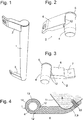
- the in Fig. 1 The handle shown is composed essentially of three parts, a long stretched cylindrical handle bar 1 and two end pieces 2, 3, from above and engage below in open ends of the hollow handlebar 1.
- the two end pieces 2, 3 are mirror images of each other and arranged, and the upper end piece 2 is in two different perspective views in FIGS. 2 and 3 shown in detail. It comprises a substantially cylindrical, engaging in the handle bar 1 pin or mandrel 4, which is tapered slightly frusto-conical at its free end to facilitate the play-free insertion into the handle bar 1.
- a flange 5 is formed whose diameter corresponds exactly to the outer diameter of the handle bar 1, so that in the assembled state, when the pin 4 is inserted into the hollow interior of the handle bar 1, the edge of the flange fifth and the peripheral surface of the handle bar 1 flush with each other.
- the pin 4 may be hollow for material saving and open at its pointed free end.
- the handle bar 1 has a two-layer construction, with a clearance on the pin 4 plugged plastic extruded inner profile 13 and a profile 13 surrounding form-fitting, thin-walled metal tube 14, preferably made of aluminum or stainless steel.
- the wall thickness of the metal tube 14 is too small, preferably about 0.5 mm, that it could withstand without the assistance of the inner profile 13, the forces occurring during the use of the handle.
- FIGS. 2 and 3 show at the transition between the pin 4 and the arm 6 of each end piece 2, 3 on three sides a groove 12.
- This groove takes in the assembled state of the handle, as in Fig. 4 to see edges of one in the handle bar 1 cut, to the ends of the handle bar 1 open towards cutout. The edges of the cutout are thereby completely hidden within the groove 12 so that the profile 13 exposed to them is not visible on the assembled handle.
- the inner profile 13 is covered by the flanges 5 of the end pieces 2, 3.
- the end pieces 2, 3 are made of metal, the handle seems as if it only consisted of solid metal.
- Fig. 5 shows a section through the handle in a plane to the Fig. 4 parallel, between the end pieces 2, 3 extending horizontal plane. It can be seen here that the profile 13 has no closed over its entire circumference tubular cross-section, but a extending in the longitudinal direction of the handle bar 1, the two cutouts connecting narrow slot 15 on a side facing away from the user, not normally visible in use page has.
- the metal tube 14 has no closed cross-section, but is formed of a metal strip by this, while it passes through an extrusion tool for the profile 13, first edge webs 16 are angled and the main part of the tape, between the edge webs 16, by he is guided together with the profile 13 through an extruder die, is bent around the tube 13 similar to the profile, wherein the edge webs 16 in the interior of the profile, the edges of the slot 15 embracing come to rest.
- this may, as in Fig. 5 indicated by a dashed outline, be provided with an inner reinforcing rib 17 which intersects the hollow interior of the profile 13.
- the rib 17 preferably runs parallel to the effective direction of an actuating force normally exerted on the handle when opening and closing the door, that is to say essentially parallel to the lateral flank 9 of the door 8.
- the profile 13 has a reinforcing rib 17, then this must either be removed before joining the handle bar 1 with the end pieces 2, 3 at the ends of the handle bar 1, or the pins 4 of the end pieces must be different from the representation of FIGS. 2 and 3 , 17 have complementary recesses to the reinforcing ribs.
- Fig. 5 is the metal tube 14 on the profile 13 over the entire surface by adhesion, which may be a result of coextrusion or mediated by an additional adhesive, and in the amount of the end pieces 2, 3 by clamping the edge webs 16 between the inner surface of the profile 13 and the pins engaging therein 4 fixed.
- Fig. 6 shows you one Fig. 5 analog cross section through the handle bar 1 according to a second embodiment of the invention.
- the profile 13 is also here substantially tubular with a non-conspicuous, remote from the user point slot 15.
- the slot 15 does not reach into the central inner cavity of the profile 13, but the edges of the slot 15 are interconnected by an in the inner cavity of the profile 13 projecting flat rib 18 integrally connected.
- the rib 18 embeds the barb-like curved edge webs 16 of the metal tube 14, which are thereby anchored positively in the profile 13 over its entire length.
- a gap 19 between opposite sides of the edge webs 16 may be filled with the plastic material of the profile 13 in order to improve the anchoring of the edge webs 16.
- Fig. 7 shows a third embodiment of the handle according to the invention in turn to one Fig. 5 analogue cut.
- the protruding into the interior of the profile rib 18 is omitted here, instead, the inside of the handle bar 1 in angled edge webs 16 are so narrow that between them and engaging in the interior cylindrical pin 4 still room for a one-piece connection 20 between two sides the slot 15 is; in other words, the profile 13 has a closed tubular cross-section whose outer periphery has two closely adjacent hook-shaped recesses or a T-shaped recess which receives the edge webs 16 of the tube 14 in a form-fitting manner.
- Fig. 8 shows in analogy to Fig. 4 a section through the handle according to the third embodiment in a plane passing through an end piece 2 or 3 level.
- Fig. 9 shown perspective view of the handle bar 1, that of the here-21 denoted - to one end of the handle bar 1 through cutout, through which the Arm 6 of the tail extends and whose edges are received in the groove 12 of the tail, is cut on only one side of the slot 15 from the profile 13; on the other side of the edge web 16 of the metal tube 14 is intact and is hooked over its entire length in the profile 13 non-positively and positively.
- the handle bar is made of a closed-walled metal tube which is stiffened by a suitable synthetic resin material is allowed to expand in one of the metal tube and the inserted into its ends end pieces 2, 3 limited internal cavity.
Landscapes
- Engineering & Computer Science (AREA)
- Chemical & Material Sciences (AREA)
- Combustion & Propulsion (AREA)
- Physics & Mathematics (AREA)
- Mechanical Engineering (AREA)
- Thermal Sciences (AREA)
- General Engineering & Computer Science (AREA)
- Wing Frames And Configurations (AREA)
- Steering Devices For Bicycles And Motorcycles (AREA)
- Securing Of Glass Panes Or The Like (AREA)
Applications Claiming Priority (2)
| Application Number | Priority Date | Filing Date | Title |
|---|---|---|---|
| DE200910026663 DE102009026663A1 (de) | 2009-06-03 | 2009-06-03 | Griff für ein Gerätegehäuse |
| PCT/EP2010/056442 WO2010139537A1 (de) | 2009-06-03 | 2010-05-11 | Griff für ein gerätegehäuse |
Publications (2)
| Publication Number | Publication Date |
|---|---|
| EP2437633A1 EP2437633A1 (de) | 2012-04-11 |
| EP2437633B1 true EP2437633B1 (de) | 2016-07-13 |
Family
ID=42358603
Family Applications (1)
| Application Number | Title | Priority Date | Filing Date |
|---|---|---|---|
| EP10718208.1A Not-in-force EP2437633B1 (de) | 2009-06-03 | 2010-05-11 | Griff für ein gerätegehäuse |
Country Status (4)
| Country | Link |
|---|---|
| EP (1) | EP2437633B1 (pl) |
| DE (1) | DE102009026663A1 (pl) |
| PL (1) | PL2437633T3 (pl) |
| WO (1) | WO2010139537A1 (pl) |
Families Citing this family (9)
| Publication number | Priority date | Publication date | Assignee | Title |
|---|---|---|---|---|
| DE102011076697A1 (de) * | 2011-05-30 | 2012-12-06 | BSH Bosch und Siemens Hausgeräte GmbH | Griff für eine Tür eines Hausgeräts sowie Hausgerätetür mit einem derartigen Griff |
| DE102011087757A1 (de) * | 2011-12-05 | 2013-06-06 | BSH Bosch und Siemens Hausgeräte GmbH | Türgriff für Haushaltsgerätetür mit Profilgriffstange |
| DE102011087754A1 (de) * | 2011-12-05 | 2013-06-06 | BSH Bosch und Siemens Hausgeräte GmbH | Türgriff mit Griffprofil und Griffböcken |
| DE102011087756A1 (de) * | 2011-12-05 | 2013-06-06 | BSH Bosch und Siemens Hausgeräte GmbH | Türgriff mit Griffprofil und Griffböcken |
| DE102014216548A1 (de) * | 2014-03-19 | 2015-09-24 | BSH Hausgeräte GmbH | Tür für ein Haushaltsgerät und eine als Hybrid-Bauteil ausgebildete Abdeckung für zumindest eine Türscheibe sowie Haushaltsgerät mit einer derartigen Tür |
| DE102015211246A1 (de) * | 2015-06-18 | 2016-12-22 | BSH Hausgeräte GmbH | Baukastensystem |
| DE102018209181A1 (de) * | 2018-06-08 | 2019-12-12 | BSH Hausgeräte GmbH | Tür für ein Haushaltsgerät mit einem zweiseitig an einem Wandelement der Tür bewegbar befestigten Griff, sowie Haushaltsgerät |
| US11300351B2 (en) * | 2020-01-03 | 2022-04-12 | Whirlpool Corporation | Handle assembly |
| KR102892226B1 (ko) * | 2020-07-10 | 2025-11-27 | 엘지전자 주식회사 | 도어개방장치 및 이를 포함하는 냉장고 |
Family Cites Families (4)
| Publication number | Priority date | Publication date | Assignee | Title |
|---|---|---|---|---|
| DE19650776A1 (de) | 1996-12-06 | 1998-06-10 | Bosch Siemens Hausgeraete | Türgriff für eine Möbeltür, insbesondere eine Kühlmöbeltür |
| ATE374346T1 (de) * | 2003-06-30 | 2007-10-15 | Arcelik As | Griff |
| DE102005019982A1 (de) * | 2005-04-27 | 2006-11-02 | Basf Ag | Kunststoffgegenstände mit metallähnlicher oder mineralähnlicher Haptik und Optik und guten Formgebungseigenschaften |
| KR20080034582A (ko) * | 2006-10-17 | 2008-04-22 | 삼성광주전자 주식회사 | 냉장고 도어용 손잡이 및 그 제조방법 |
-
2009
- 2009-06-03 DE DE200910026663 patent/DE102009026663A1/de not_active Withdrawn
-
2010
- 2010-05-11 PL PL10718208.1T patent/PL2437633T3/pl unknown
- 2010-05-11 EP EP10718208.1A patent/EP2437633B1/de not_active Not-in-force
- 2010-05-11 WO PCT/EP2010/056442 patent/WO2010139537A1/de not_active Ceased
Also Published As
| Publication number | Publication date |
|---|---|
| EP2437633A1 (de) | 2012-04-11 |
| PL2437633T3 (pl) | 2016-12-30 |
| DE102009026663A1 (de) | 2010-12-09 |
| WO2010139537A1 (de) | 2010-12-09 |
Similar Documents
| Publication | Publication Date | Title |
|---|---|---|
| EP2437633A1 (de) | Griff für ein gerätegehäuse | |
| EP1709270B1 (de) | Klipsbefestigung für die montage von beschlageinrichtungen, wie verschlüsse, scharnierteile, griffe in durchbrüchen in einer dünnen wand | |
| DE69923240T2 (de) | Türfallenanschlag | |
| EP1599113B1 (de) | Türgriff | |
| DE102009032990A1 (de) | Männliches Hybrid-Verbundwerkstoff-Metall-Befestigungselement | |
| EP3097313B1 (de) | Schraube, befestigungsanordnung und verwendung einer schraube | |
| EP0930133B1 (de) | Kelle mit Griff | |
| WO2009030480A2 (de) | Befestiger | |
| DE202006013666U1 (de) | Schnellverschluss zum Verbinden zweier Bauteile | |
| DE102009031829C5 (de) | Band aus wenigen Teilen und Herstellungsverfahren hierfür | |
| DE2000971C3 (de) | Spreizdübel, insbesondere für kleine Lasten | |
| EP1305859B1 (de) | Bauteil mit einem hohlquerschnitt | |
| EP3540160A1 (de) | Befestigungsanordnung zum befestigen eines türbandes an einem hohlkammer-profil | |
| DE202008015732U1 (de) | Beschlag zum Festlegen einer Leichtbauplatte | |
| DE202007013321U1 (de) | Extrusionsblasgeformtes Bauteil aus thermoplastischem Kunststoff | |
| DE2947299C2 (pl) | ||
| WO2014048989A1 (de) | Montageschraube zur befestigung von beschlagteilen an hohlkammerprofilen, bausatz einer montageschraube und anordnung eines mehrkammerprofils und einer montagschraube | |
| DE9419781U1 (de) | Kunststoffprofilteil | |
| DE102008011334A1 (de) | Griffbefestigung | |
| DE19639893A1 (de) | Eckumlenkung für einen Beschlag, insbesondere Treibstangenbeschlag für Fenster, Türen o. dgl. | |
| EP2305932B1 (de) | Bandteil mit verdeckter Verschraubung | |
| EP2708760B1 (de) | Dämmelement einer Wandankeranordnung | |
| DE3725719A1 (de) | Verfahren und vorrichtung zur befestigung eines griffes, oder dergleichen | |
| DE102006019245B4 (de) | Handwerkzeug | |
| DE102018107905A1 (de) | Konstruktionselement und Verfahren zur Herstellung eines solchen |
Legal Events
| Date | Code | Title | Description |
|---|---|---|---|
| PUAI | Public reference made under article 153(3) epc to a published international application that has entered the european phase |
Free format text: ORIGINAL CODE: 0009012 |
|
| 17P | Request for examination filed |
Effective date: 20120103 |
|
| AK | Designated contracting states |
Kind code of ref document: A1 Designated state(s): AL AT BE BG CH CY CZ DE DK EE ES FI FR GB GR HR HU IE IS IT LI LT LU LV MC MK MT NL NO PL PT RO SE SI SK SM TR |
|
| DAX | Request for extension of the european patent (deleted) | ||
| RAP1 | Party data changed (applicant data changed or rights of an application transferred) |
Owner name: BSH HAUSGERAETE GMBH |
|
| GRAP | Despatch of communication of intention to grant a patent |
Free format text: ORIGINAL CODE: EPIDOSNIGR1 |
|
| INTG | Intention to grant announced |
Effective date: 20160211 |
|
| GRAS | Grant fee paid |
Free format text: ORIGINAL CODE: EPIDOSNIGR3 |
|
| GRAA | (expected) grant |
Free format text: ORIGINAL CODE: 0009210 |
|
| AK | Designated contracting states |
Kind code of ref document: B1 Designated state(s): AL AT BE BG CH CY CZ DE DK EE ES FI FR GB GR HR HU IE IS IT LI LT LU LV MC MK MT NL NO PL PT RO SE SI SK SM TR |
|
| REG | Reference to a national code |
Ref country code: GB Ref legal event code: FG4D Free format text: NOT ENGLISH |
|
| REG | Reference to a national code |
Ref country code: AT Ref legal event code: REF Ref document number: 811568 Country of ref document: AT Kind code of ref document: T Effective date: 20160715 Ref country code: CH Ref legal event code: EP |
|
| REG | Reference to a national code |
Ref country code: IE Ref legal event code: FG4D Free format text: LANGUAGE OF EP DOCUMENT: GERMAN |
|
| REG | Reference to a national code |
Ref country code: DE Ref legal event code: R096 Ref document number: 502010012006 Country of ref document: DE |
|
| REG | Reference to a national code |
Ref country code: LT Ref legal event code: MG4D |
|
| REG | Reference to a national code |
Ref country code: NL Ref legal event code: MP Effective date: 20160713 |
|
| PG25 | Lapsed in a contracting state [announced via postgrant information from national office to epo] |
Ref country code: LT Free format text: LAPSE BECAUSE OF FAILURE TO SUBMIT A TRANSLATION OF THE DESCRIPTION OR TO PAY THE FEE WITHIN THE PRESCRIBED TIME-LIMIT Effective date: 20160713 Ref country code: HR Free format text: LAPSE BECAUSE OF FAILURE TO SUBMIT A TRANSLATION OF THE DESCRIPTION OR TO PAY THE FEE WITHIN THE PRESCRIBED TIME-LIMIT Effective date: 20160713 Ref country code: FI Free format text: LAPSE BECAUSE OF FAILURE TO SUBMIT A TRANSLATION OF THE DESCRIPTION OR TO PAY THE FEE WITHIN THE PRESCRIBED TIME-LIMIT Effective date: 20160713 Ref country code: IS Free format text: LAPSE BECAUSE OF FAILURE TO SUBMIT A TRANSLATION OF THE DESCRIPTION OR TO PAY THE FEE WITHIN THE PRESCRIBED TIME-LIMIT Effective date: 20161113 Ref country code: NL Free format text: LAPSE BECAUSE OF FAILURE TO SUBMIT A TRANSLATION OF THE DESCRIPTION OR TO PAY THE FEE WITHIN THE PRESCRIBED TIME-LIMIT Effective date: 20160713 Ref country code: NO Free format text: LAPSE BECAUSE OF FAILURE TO SUBMIT A TRANSLATION OF THE DESCRIPTION OR TO PAY THE FEE WITHIN THE PRESCRIBED TIME-LIMIT Effective date: 20161013 |
|
| PG25 | Lapsed in a contracting state [announced via postgrant information from national office to epo] |
Ref country code: LV Free format text: LAPSE BECAUSE OF FAILURE TO SUBMIT A TRANSLATION OF THE DESCRIPTION OR TO PAY THE FEE WITHIN THE PRESCRIBED TIME-LIMIT Effective date: 20160713 Ref country code: PT Free format text: LAPSE BECAUSE OF FAILURE TO SUBMIT A TRANSLATION OF THE DESCRIPTION OR TO PAY THE FEE WITHIN THE PRESCRIBED TIME-LIMIT Effective date: 20161114 Ref country code: SE Free format text: LAPSE BECAUSE OF FAILURE TO SUBMIT A TRANSLATION OF THE DESCRIPTION OR TO PAY THE FEE WITHIN THE PRESCRIBED TIME-LIMIT Effective date: 20160713 Ref country code: GR Free format text: LAPSE BECAUSE OF FAILURE TO SUBMIT A TRANSLATION OF THE DESCRIPTION OR TO PAY THE FEE WITHIN THE PRESCRIBED TIME-LIMIT Effective date: 20161014 Ref country code: ES Free format text: LAPSE BECAUSE OF FAILURE TO SUBMIT A TRANSLATION OF THE DESCRIPTION OR TO PAY THE FEE WITHIN THE PRESCRIBED TIME-LIMIT Effective date: 20160713 |
|
| REG | Reference to a national code |
Ref country code: DE Ref legal event code: R097 Ref document number: 502010012006 Country of ref document: DE |
|
| PG25 | Lapsed in a contracting state [announced via postgrant information from national office to epo] |
Ref country code: EE Free format text: LAPSE BECAUSE OF FAILURE TO SUBMIT A TRANSLATION OF THE DESCRIPTION OR TO PAY THE FEE WITHIN THE PRESCRIBED TIME-LIMIT Effective date: 20160713 Ref country code: RO Free format text: LAPSE BECAUSE OF FAILURE TO SUBMIT A TRANSLATION OF THE DESCRIPTION OR TO PAY THE FEE WITHIN THE PRESCRIBED TIME-LIMIT Effective date: 20160713 |
|
| PLBE | No opposition filed within time limit |
Free format text: ORIGINAL CODE: 0009261 |
|
| STAA | Information on the status of an ep patent application or granted ep patent |
Free format text: STATUS: NO OPPOSITION FILED WITHIN TIME LIMIT |
|
| PG25 | Lapsed in a contracting state [announced via postgrant information from national office to epo] |
Ref country code: SK Free format text: LAPSE BECAUSE OF FAILURE TO SUBMIT A TRANSLATION OF THE DESCRIPTION OR TO PAY THE FEE WITHIN THE PRESCRIBED TIME-LIMIT Effective date: 20160713 Ref country code: BG Free format text: LAPSE BECAUSE OF FAILURE TO SUBMIT A TRANSLATION OF THE DESCRIPTION OR TO PAY THE FEE WITHIN THE PRESCRIBED TIME-LIMIT Effective date: 20161013 Ref country code: CZ Free format text: LAPSE BECAUSE OF FAILURE TO SUBMIT A TRANSLATION OF THE DESCRIPTION OR TO PAY THE FEE WITHIN THE PRESCRIBED TIME-LIMIT Effective date: 20160713 Ref country code: SM Free format text: LAPSE BECAUSE OF FAILURE TO SUBMIT A TRANSLATION OF THE DESCRIPTION OR TO PAY THE FEE WITHIN THE PRESCRIBED TIME-LIMIT Effective date: 20160713 Ref country code: DK Free format text: LAPSE BECAUSE OF FAILURE TO SUBMIT A TRANSLATION OF THE DESCRIPTION OR TO PAY THE FEE WITHIN THE PRESCRIBED TIME-LIMIT Effective date: 20160713 |
|
| 26N | No opposition filed |
Effective date: 20170418 |
|
| PG25 | Lapsed in a contracting state [announced via postgrant information from national office to epo] |
Ref country code: LU Free format text: LAPSE BECAUSE OF NON-PAYMENT OF DUE FEES Effective date: 20170531 Ref country code: SI Free format text: LAPSE BECAUSE OF FAILURE TO SUBMIT A TRANSLATION OF THE DESCRIPTION OR TO PAY THE FEE WITHIN THE PRESCRIBED TIME-LIMIT Effective date: 20160713 |
|
| REG | Reference to a national code |
Ref country code: CH Ref legal event code: PL |
|
| GBPC | Gb: european patent ceased through non-payment of renewal fee |
Effective date: 20170511 |
|
| PG25 | Lapsed in a contracting state [announced via postgrant information from national office to epo] |
Ref country code: MC Free format text: LAPSE BECAUSE OF FAILURE TO SUBMIT A TRANSLATION OF THE DESCRIPTION OR TO PAY THE FEE WITHIN THE PRESCRIBED TIME-LIMIT Effective date: 20160713 |
|
| REG | Reference to a national code |
Ref country code: IE Ref legal event code: MM4A |
|
| PG25 | Lapsed in a contracting state [announced via postgrant information from national office to epo] |
Ref country code: CH Free format text: LAPSE BECAUSE OF NON-PAYMENT OF DUE FEES Effective date: 20170531 Ref country code: LI Free format text: LAPSE BECAUSE OF NON-PAYMENT OF DUE FEES Effective date: 20170531 |
|
| REG | Reference to a national code |
Ref country code: FR Ref legal event code: ST Effective date: 20180131 |
|
| PG25 | Lapsed in a contracting state [announced via postgrant information from national office to epo] |
Ref country code: LU Free format text: LAPSE BECAUSE OF NON-PAYMENT OF DUE FEES Effective date: 20170511 |
|
| REG | Reference to a national code |
Ref country code: BE Ref legal event code: MM Effective date: 20170531 |
|
| PG25 | Lapsed in a contracting state [announced via postgrant information from national office to epo] |
Ref country code: IE Free format text: LAPSE BECAUSE OF NON-PAYMENT OF DUE FEES Effective date: 20170511 Ref country code: GB Free format text: LAPSE BECAUSE OF NON-PAYMENT OF DUE FEES Effective date: 20170511 |
|
| PG25 | Lapsed in a contracting state [announced via postgrant information from national office to epo] |
Ref country code: FR Free format text: LAPSE BECAUSE OF NON-PAYMENT OF DUE FEES Effective date: 20170531 |
|
| REG | Reference to a national code |
Ref country code: AT Ref legal event code: MM01 Ref document number: 811568 Country of ref document: AT Kind code of ref document: T Effective date: 20170511 |
|
| PG25 | Lapsed in a contracting state [announced via postgrant information from national office to epo] |
Ref country code: AT Free format text: LAPSE BECAUSE OF NON-PAYMENT OF DUE FEES Effective date: 20170511 Ref country code: BE Free format text: LAPSE BECAUSE OF NON-PAYMENT OF DUE FEES Effective date: 20170531 |
|
| PGFP | Annual fee paid to national office [announced via postgrant information from national office to epo] |
Ref country code: IT Payment date: 20180518 Year of fee payment: 9 Ref country code: TR Payment date: 20180504 Year of fee payment: 9 Ref country code: PL Payment date: 20180509 Year of fee payment: 9 |
|
| PG25 | Lapsed in a contracting state [announced via postgrant information from national office to epo] |
Ref country code: MT Free format text: LAPSE BECAUSE OF FAILURE TO SUBMIT A TRANSLATION OF THE DESCRIPTION OR TO PAY THE FEE WITHIN THE PRESCRIBED TIME-LIMIT Effective date: 20160713 |
|
| PG25 | Lapsed in a contracting state [announced via postgrant information from national office to epo] |
Ref country code: AL Free format text: LAPSE BECAUSE OF FAILURE TO SUBMIT A TRANSLATION OF THE DESCRIPTION OR TO PAY THE FEE WITHIN THE PRESCRIBED TIME-LIMIT Effective date: 20160713 |
|
| PG25 | Lapsed in a contracting state [announced via postgrant information from national office to epo] |
Ref country code: HU Free format text: LAPSE BECAUSE OF FAILURE TO SUBMIT A TRANSLATION OF THE DESCRIPTION OR TO PAY THE FEE WITHIN THE PRESCRIBED TIME-LIMIT; INVALID AB INITIO Effective date: 20100511 |
|
| PG25 | Lapsed in a contracting state [announced via postgrant information from national office to epo] |
Ref country code: CY Free format text: LAPSE BECAUSE OF NON-PAYMENT OF DUE FEES Effective date: 20160713 |
|
| PG25 | Lapsed in a contracting state [announced via postgrant information from national office to epo] |
Ref country code: MK Free format text: LAPSE BECAUSE OF FAILURE TO SUBMIT A TRANSLATION OF THE DESCRIPTION OR TO PAY THE FEE WITHIN THE PRESCRIBED TIME-LIMIT Effective date: 20160713 |
|
| PG25 | Lapsed in a contracting state [announced via postgrant information from national office to epo] |
Ref country code: IT Free format text: LAPSE BECAUSE OF NON-PAYMENT OF DUE FEES Effective date: 20190511 |
|
| PG25 | Lapsed in a contracting state [announced via postgrant information from national office to epo] |
Ref country code: PL Free format text: LAPSE BECAUSE OF NON-PAYMENT OF DUE FEES Effective date: 20190511 |
|
| PG25 | Lapsed in a contracting state [announced via postgrant information from national office to epo] |
Ref country code: TR Free format text: LAPSE BECAUSE OF NON-PAYMENT OF DUE FEES Effective date: 20190511 |
|
| REG | Reference to a national code |
Ref country code: DE Ref legal event code: R084 Ref document number: 502010012006 Country of ref document: DE |
|
| PGFP | Annual fee paid to national office [announced via postgrant information from national office to epo] |
Ref country code: DE Payment date: 20230531 Year of fee payment: 14 |
|
| REG | Reference to a national code |
Ref country code: DE Ref legal event code: R119 Ref document number: 502010012006 Country of ref document: DE |
|
| PG25 | Lapsed in a contracting state [announced via postgrant information from national office to epo] |
Ref country code: DE Free format text: LAPSE BECAUSE OF NON-PAYMENT OF DUE FEES Effective date: 20241203 |