EP2433325B1 - Pasted zinc electrode for rechargeable zinc batteries - Google Patents
Pasted zinc electrode for rechargeable zinc batteries Download PDFInfo
- Publication number
- EP2433325B1 EP2433325B1 EP10724181.2A EP10724181A EP2433325B1 EP 2433325 B1 EP2433325 B1 EP 2433325B1 EP 10724181 A EP10724181 A EP 10724181A EP 2433325 B1 EP2433325 B1 EP 2433325B1
- Authority
- EP
- European Patent Office
- Prior art keywords
- zinc
- cobalt
- tin
- particles
- lead
- Prior art date
- Legal status (The legal status is an assumption and is not a legal conclusion. Google has not performed a legal analysis and makes no representation as to the accuracy of the status listed.)
- Active
Links
Images


Classifications
-
- H—ELECTRICITY
- H01—ELECTRIC ELEMENTS
- H01M—PROCESSES OR MEANS, e.g. BATTERIES, FOR THE DIRECT CONVERSION OF CHEMICAL ENERGY INTO ELECTRICAL ENERGY
- H01M10/00—Secondary cells; Manufacture thereof
- H01M10/24—Alkaline accumulators
- H01M10/30—Nickel accumulators
-
- H—ELECTRICITY
- H01—ELECTRIC ELEMENTS
- H01M—PROCESSES OR MEANS, e.g. BATTERIES, FOR THE DIRECT CONVERSION OF CHEMICAL ENERGY INTO ELECTRICAL ENERGY
- H01M4/00—Electrodes
-
- H—ELECTRICITY
- H01—ELECTRIC ELEMENTS
- H01M—PROCESSES OR MEANS, e.g. BATTERIES, FOR THE DIRECT CONVERSION OF CHEMICAL ENERGY INTO ELECTRICAL ENERGY
- H01M4/00—Electrodes
- H01M4/02—Electrodes composed of, or comprising, active material
- H01M4/04—Processes of manufacture in general
-
- H—ELECTRICITY
- H01—ELECTRIC ELEMENTS
- H01M—PROCESSES OR MEANS, e.g. BATTERIES, FOR THE DIRECT CONVERSION OF CHEMICAL ENERGY INTO ELECTRICAL ENERGY
- H01M4/00—Electrodes
- H01M4/02—Electrodes composed of, or comprising, active material
- H01M4/04—Processes of manufacture in general
- H01M4/0402—Methods of deposition of the material
- H01M4/0404—Methods of deposition of the material by coating on electrode collectors
-
- H—ELECTRICITY
- H01—ELECTRIC ELEMENTS
- H01M—PROCESSES OR MEANS, e.g. BATTERIES, FOR THE DIRECT CONVERSION OF CHEMICAL ENERGY INTO ELECTRICAL ENERGY
- H01M4/00—Electrodes
- H01M4/02—Electrodes composed of, or comprising, active material
- H01M4/04—Processes of manufacture in general
- H01M4/0402—Methods of deposition of the material
- H01M4/0416—Methods of deposition of the material involving impregnation with a solution, dispersion, paste or dry powder
-
- H—ELECTRICITY
- H01—ELECTRIC ELEMENTS
- H01M—PROCESSES OR MEANS, e.g. BATTERIES, FOR THE DIRECT CONVERSION OF CHEMICAL ENERGY INTO ELECTRICAL ENERGY
- H01M4/00—Electrodes
- H01M4/02—Electrodes composed of, or comprising, active material
- H01M4/13—Electrodes for accumulators with non-aqueous electrolyte, e.g. for lithium-accumulators; Processes of manufacture thereof
- H01M4/134—Electrodes based on metals, Si or alloys
-
- H—ELECTRICITY
- H01—ELECTRIC ELEMENTS
- H01M—PROCESSES OR MEANS, e.g. BATTERIES, FOR THE DIRECT CONVERSION OF CHEMICAL ENERGY INTO ELECTRICAL ENERGY
- H01M4/00—Electrodes
- H01M4/02—Electrodes composed of, or comprising, active material
- H01M4/13—Electrodes for accumulators with non-aqueous electrolyte, e.g. for lithium-accumulators; Processes of manufacture thereof
- H01M4/139—Processes of manufacture
- H01M4/1395—Processes of manufacture of electrodes based on metals, Si or alloys
-
- H—ELECTRICITY
- H01—ELECTRIC ELEMENTS
- H01M—PROCESSES OR MEANS, e.g. BATTERIES, FOR THE DIRECT CONVERSION OF CHEMICAL ENERGY INTO ELECTRICAL ENERGY
- H01M4/00—Electrodes
- H01M4/02—Electrodes composed of, or comprising, active material
- H01M4/24—Electrodes for alkaline accumulators
-
- H—ELECTRICITY
- H01—ELECTRIC ELEMENTS
- H01M—PROCESSES OR MEANS, e.g. BATTERIES, FOR THE DIRECT CONVERSION OF CHEMICAL ENERGY INTO ELECTRICAL ENERGY
- H01M4/00—Electrodes
- H01M4/02—Electrodes composed of, or comprising, active material
- H01M4/24—Electrodes for alkaline accumulators
- H01M4/244—Zinc electrodes
-
- H—ELECTRICITY
- H01—ELECTRIC ELEMENTS
- H01M—PROCESSES OR MEANS, e.g. BATTERIES, FOR THE DIRECT CONVERSION OF CHEMICAL ENERGY INTO ELECTRICAL ENERGY
- H01M4/00—Electrodes
- H01M4/02—Electrodes composed of, or comprising, active material
- H01M4/24—Electrodes for alkaline accumulators
- H01M4/26—Processes of manufacture
-
- H—ELECTRICITY
- H01—ELECTRIC ELEMENTS
- H01M—PROCESSES OR MEANS, e.g. BATTERIES, FOR THE DIRECT CONVERSION OF CHEMICAL ENERGY INTO ELECTRICAL ENERGY
- H01M4/00—Electrodes
- H01M4/02—Electrodes composed of, or comprising, active material
- H01M4/24—Electrodes for alkaline accumulators
- H01M4/32—Nickel oxide or hydroxide electrodes
-
- H—ELECTRICITY
- H01—ELECTRIC ELEMENTS
- H01M—PROCESSES OR MEANS, e.g. BATTERIES, FOR THE DIRECT CONVERSION OF CHEMICAL ENERGY INTO ELECTRICAL ENERGY
- H01M4/00—Electrodes
- H01M4/02—Electrodes composed of, or comprising, active material
- H01M4/36—Selection of substances as active materials, active masses, active liquids
- H01M4/38—Selection of substances as active materials, active masses, active liquids of elements or alloys
-
- H—ELECTRICITY
- H01—ELECTRIC ELEMENTS
- H01M—PROCESSES OR MEANS, e.g. BATTERIES, FOR THE DIRECT CONVERSION OF CHEMICAL ENERGY INTO ELECTRICAL ENERGY
- H01M4/00—Electrodes
- H01M4/02—Electrodes composed of, or comprising, active material
- H01M4/62—Selection of inactive substances as ingredients for active masses, e.g. binders, fillers
- H01M4/621—Binders
-
- H—ELECTRICITY
- H01—ELECTRIC ELEMENTS
- H01M—PROCESSES OR MEANS, e.g. BATTERIES, FOR THE DIRECT CONVERSION OF CHEMICAL ENERGY INTO ELECTRICAL ENERGY
- H01M4/00—Electrodes
- H01M4/02—Electrodes composed of, or comprising, active material
- H01M2004/021—Physical characteristics, e.g. porosity, surface area
-
- H—ELECTRICITY
- H01—ELECTRIC ELEMENTS
- H01M—PROCESSES OR MEANS, e.g. BATTERIES, FOR THE DIRECT CONVERSION OF CHEMICAL ENERGY INTO ELECTRICAL ENERGY
- H01M4/00—Electrodes
- H01M4/02—Electrodes composed of, or comprising, active material
- H01M2004/026—Electrodes composed of, or comprising, active material characterised by the polarity
- H01M2004/027—Negative electrodes
-
- Y—GENERAL TAGGING OF NEW TECHNOLOGICAL DEVELOPMENTS; GENERAL TAGGING OF CROSS-SECTIONAL TECHNOLOGIES SPANNING OVER SEVERAL SECTIONS OF THE IPC; TECHNICAL SUBJECTS COVERED BY FORMER USPC CROSS-REFERENCE ART COLLECTIONS [XRACs] AND DIGESTS
- Y02—TECHNOLOGIES OR APPLICATIONS FOR MITIGATION OR ADAPTATION AGAINST CLIMATE CHANGE
- Y02E—REDUCTION OF GREENHOUSE GAS [GHG] EMISSIONS, RELATED TO ENERGY GENERATION, TRANSMISSION OR DISTRIBUTION
- Y02E60/00—Enabling technologies; Technologies with a potential or indirect contribution to GHG emissions mitigation
- Y02E60/10—Energy storage using batteries
-
- Y—GENERAL TAGGING OF NEW TECHNOLOGICAL DEVELOPMENTS; GENERAL TAGGING OF CROSS-SECTIONAL TECHNOLOGIES SPANNING OVER SEVERAL SECTIONS OF THE IPC; TECHNICAL SUBJECTS COVERED BY FORMER USPC CROSS-REFERENCE ART COLLECTIONS [XRACs] AND DIGESTS
- Y02—TECHNOLOGIES OR APPLICATIONS FOR MITIGATION OR ADAPTATION AGAINST CLIMATE CHANGE
- Y02P—CLIMATE CHANGE MITIGATION TECHNOLOGIES IN THE PRODUCTION OR PROCESSING OF GOODS
- Y02P70/00—Climate change mitigation technologies in the production process for final industrial or consumer products
- Y02P70/50—Manufacturing or production processes characterised by the final manufactured product
-
- Y—GENERAL TAGGING OF NEW TECHNOLOGICAL DEVELOPMENTS; GENERAL TAGGING OF CROSS-SECTIONAL TECHNOLOGIES SPANNING OVER SEVERAL SECTIONS OF THE IPC; TECHNICAL SUBJECTS COVERED BY FORMER USPC CROSS-REFERENCE ART COLLECTIONS [XRACs] AND DIGESTS
- Y10—TECHNICAL SUBJECTS COVERED BY FORMER USPC
- Y10T—TECHNICAL SUBJECTS COVERED BY FORMER US CLASSIFICATION
- Y10T29/00—Metal working
- Y10T29/49—Method of mechanical manufacture
- Y10T29/49002—Electrical device making
- Y10T29/49108—Electric battery cell making
- Y10T29/49115—Electric battery cell making including coating or impregnating
Definitions
- This invention pertains generally to rechargeable batteries and specifically rechargeable nickel-zinc batteries. More specifically, this invention pertains to the composition and manufacturing methods for a negative zinc electrode used in rechargeable nickel-zinc batteries.
- the alkaline zinc electrode is known for its high voltage, low equivalent weight and low cost. The fast electrochemical kinetics associated with the charge and discharge process enables the zinc electrode to deliver both high power and high energy density.
- Zinc primary batteries are manufactured in a charged state while zinc secondary batteries are manufactured in a largely discharged state.
- the active material is metallic zinc in a gelled powder form with particles between 100 to 300 microns.
- the active material is zinc oxide (ZnO), with small amounts of zinc metal, with particle size on the order of 0.2 to 0.3 microns.
- ZnO zinc oxide
- the small zinc oxide particle size used in the negative electrode of rechargeable cells results in a surface area that is two orders of magnitude larger than the particles in zinc electrodes used in primary batteries.
- the corrosion rate of zinc is significantly higher in a secondary battery, once it is formed after the initial charge. Improvements in rechargeable zinc electrode composition and manufacturing technique to minimize corrosion and improve manufacturability continue to be sought.
- JPH10144313 A is directed to an alkaline zinc secondary battery in which zinc is used for active material for a negative electrode and deterioration of the zinc electrode is purportedly reduced.
- zinc powder is coated with tin by adding soda water solution of metastannic acid to zinc powder during wet stirring, it is dehydrated, washed and vacuum dried at a room temperature, and a negative electrode with a thickness of 0.6 mm is made by rolling and pressing a negative electrode active material produced by adding and combining 50 parts of the coated zinc powder obtained, 50 parts of zinc oxide powder and 5 of PTFE.
- the negative electrode obtained is wound with intervention of a sintered nickel hydroxide positive electrode and nonwoven fabric cellophane similar to nylon as a separator, and a sealed type alkaline zinc secondary battery with a nominal capacity of 500mAh is made by adding 0.5% indium hydroxide to 4.5% KOH water solution saturated with zinc oxide as electrolyte.
- GB 144695 A is directed to a nickel-zinc storage battery wherein a sheet-like separator is interposed between a sheet-like zinc electrode and a sheet-like nickel electrode, and an alkali solution is employed as the electrolyte, said nickel-zinc storage battery characterized in that said sheet-like zinc electrode is prepared by bonding to a collector a sheet consisting of a binder and a fine granulated mixture of 60 to 99 5 weight percent, or preferably 79 to 98 weight percent, of finegranulated zinc and/or zinc oxide, balance of fine granulated material comprising at least one material selected from the group consisting of bismuth, cadmium, thallium, tin, selenium, tellurium, indium, lead, the metal oxides thereof, the hydroxide thereof and calcium hydroxide; and said sheet-like separator is prepared by coating an alkali-resisting porous body with a mixture of polyvinyl alcohol and a material selected from the group consisting of the metal oxides
- WO2006094110 A2 describes methods of manufacturing a rechargeable power cell.
- the methods in include providing a slurry, paste, or dry mixture of negative electrode materials having low toxicity and including dispersants to prevent the agglomeration of particles that may adversely affect the performance of power cells.
- the methods utilize semi-permeable sheets to separate the electrodes and minimize formation of dendrites; and further provide electrode specific electrolyte to achieve efficient electrochemistry and to further discourage dendritic growth in the cell.
- the negative electrode materials may be comprised of zinc and zinc compounds. Zinc and zinc compounds are notably less toxic than the cadmium used in nickel cadmium batteries.
- the described methods may utilize some production techniques employed in existing NiCad production lines.
- US 6787265 B2 is directed to a nickel-zinc galvanic cell having a pasted zinc oxide negative electrode, a pasted nickel oxide positive electrode, and an alkaline electrolyte. Chemical additives are placed in each of the negative and positive electrodes.
- the positive nickel hydroxide electrode contains a mixture of co-precipitated cobalt oxide in the range of 1% to 10%, and freely added, finely divided cobalt metal in the range of 1% to 5%, by weight.
- the negative zinc oxide electrode contains oxides other than the oxide of zinc, which have redox potentials which are negative of 0.73 volts.
- the metal oxide additives to the negative zinc oxide electrode are such as to inhibit release of soluble cobalt from the nickel oxide negative electrode prior to a formation charge being applied to the electrochemical cell.
- the nickel-zinc cell contains 1% to 15% of the defined metal oxides, having a solubility less than 10 -4 M in the alkaline electrolyte.
- active material for a negative electrode of a rechargeable zinc alkaline electrochemical cell is made with zinc metal particles coated with tin and/or lead.
- the zinc particles may be coated by adding lead and tin salts to a mixture containing zinc particles, a thickening agent and water.
- the remaining zinc electrode constituents such as zinc oxide (ZnO), bismuth oxide (Bi 2 O 3 ), a dispersing agent, and a binding agent such as Teflon are then added.
- the zinc metal can be coated while in the presence of zinc oxide and other constituents of the electrode.
- the resulting slurry/paste has a stable viscosity and is easy to work with during manufacture of the zinc electrode.
- the zinc electrode is much less prone to gassing when cobalt is present in the electrolyte.
- Cells manufactured from electrodes produced in accordance with this invention exhibit much less hydrogen gassing, by as much as 60-80%, than conventional cells.
- the cycle life and shelf life of the cells is also enhanced, as the zinc conductive matrix remains intact and shelf discharge is reduced.
- the present invention pertains to a rechargeable nickel zinc cell having a negative zinc electrode.
- the electrode includes zinc powder particles that are coated with lead, tin or both and are less than 100 microns in size, for example, less than 40 microns in size, about 25 microns in size, or about 5-15 microns in size.
- Metallic zinc particles are added in the electrode to create and maintain a conductive matrix during cycling. Lead and tin, being nobler than zinc, will not be discharged at the zinc potential and will protect the zinc particles they coat. The electrode will maintain better connectivity during discharge. Only small amounts of lead and tin are used.
- the nickel zinc cell also includes a positive nickel electrode.
- the positive electrode contains cobalt metal and/or a cobalt compound, which may be a coated onto nickel hydroxide particles or be added to the positive electrode separately either as cobalt metal, cobalt oxide, cobalt hydroxide, cobalt oxyhydroxide, and/or other cobalt compounds.
- the cobalt metal when present, comprises particles of cobalt metal.
- the cobalt compound when present, comprises particles of cobalt oxide, cobalt hydroxide, and/or cobalt oxyhydroxide.
- the positive electrode also includes nickel hydroxide particles.
- the present invention in accordance with claim 5, pertains to a method of making a rechargeable nickel zinc cell, which comprises (1) making a zinc negative electrode by a method which includes coating lead and/or tin onto zinc metal particles which are less than 100 microns in size, preferably in a slurry, using the zinc particles to form an active material slurry/paste, and incorporating the active material into a zinc electrode.
- at least one soluble tin salt and at least one soluble lead salt is added to zinc metal particles in a liquid medium, preferably water, to coat the zinc particles.
- the liquid medium may also include a thickening agent (a thixotropic agent), and/or a binder.
- the tin and lead is allowed to coat the zinc particle.
- the tin salt may be one or more of tin sulfate, tin acetate, tin fluoborate, tin chloride, and tin nitrate.
- the lead salt may be one or more of lead acetate, lead chloride, lead fluoborate, or lead nitrate.
- the coating operation may result in a slurry that can be used to form the active material.
- the slurry may be treated before being incorporated into the active material.
- the slurry may be concentrated, heated, or washed.
- the zinc particle slurry may also include some residual tin and lead salt in solution. The residual tin and lead salt may subsequently coat electrochemically formed zinc (after cell formation) to further protect the zinc from corrosion.
- An active material slurry/paste is formed using the zinc particle slurry.
- Remaining zinc electrode constituents are added to the slurry. These constituents include zinc oxide, bismuth oxide, a dispersing agent, a binding agent, and a liquid. Other additives may be included such as an insoluble corrosion inhibiting agent. These constituents may be in a pre-mixed powder form when added to the slurry, forming a slurry or paste that may be worked after mixing.
- An aspect of the manufacturing of the negative electrodes is the slurry and paste's stability over the time period of manufacturing. The paste/slurry needs to be stable over the time period from slurry preparation to pasting on the substrate - a process that may take 4-6 hours or more.
- the soluble lead and soluble tin may be added separately.
- a pre-dissolved tin salt solution may be added to the active material paste after the remaining zinc electrode constituents.
- the lead concentration in the paste is at most 0.05% by weight, and the tin concentration is at most 1% by weight.
- the method further comprises (2) combining the zinc negative electrode with a nickel positive electrode to form the rechargeable nickel zinc cell, wherein the nickel positive electrode is as defined above in accordance with the first aspect.
- Zinc particles are added to the electrode in manufacturing to create and maintain a conductive matrix in the electrode during cycling.
- the metallic zinc particles used are larger than the zinc oxide particles and are less than 100 microns, or less than 40 microns in size.
- the size of the metallic zinc particles may prevent complete discharge to leave an intact internal core that despite its metallic character may lose connectivity due to insulating surface oxides. Keeping an inert but conductive layer, i.e. tin and lead, on the surface of zinc particle will help maintain the integrity of zinc particles.
- the present invention pertains to the use of an as-fabricated zinc electrode in a rechargeable nickel zinc cell comprising a nickel positive electrode as defined above in accordance with the first and second aspects.
- the electrode includes a conductive substrate layer and an active material layer having zinc oxide, zinc particles coated with lead and/or tin, bismuth oxide, and a binding agent.
- the zinc particles may be coated using the process described herein or be procured precoated with the a specified amount of lead and/or tin.
- the lead concentration in the active material is at most 0.05% by weight, and the tin concentration is at most 1% by weight.
- Embodiments of the present invention are described herein in the context of manufacturing a negative zinc-zinc oxide electrode and in the context of a negative zinc-zinc oxide active material for a nickel-zinc cell.
- Those of ordinary skill in the art will realize that the following detailed description of the present invention is illustrative only and is not intended to be in any way limiting.
- the terms “battery” and “cell” may be used interchangeably.
- the present invention provides an improved process for making negative electrodes for use in rechargeable zinc cells.
- the present invention renders the manufacturing process much more manageable.
- the resulting rechargeable cells of the present invention possess one or more of the following characteristics: long shelf life, long cycle life, low leakage and little or no bulging.
- Conventional positive nickel electrodes include cobalt particles in the active material.
- the cobalt particles may be provided as cobalt metal and/or cobalt oxide (or sometimes cobalt hydroxide or cobalt oxyhydroxide).
- the inventors have appreciated that dissolved cobalt may migrate from the positive electrode before the formation process of the cell is completed. The migration may occur during the time period between filling the cell with electrolyte and the application of the first charge or during the first charge which is part of the formation process of the electrochemical cell.
- the cobalt migration is less of an issue for a sintered positive electrode than a pasted positive electrode.
- the source of the cobalt also affects whether it would dissolve in the electrolyte and migrate to the positive electrode.
- cobalt/cobalt compounds are more likely to migrate than cobalt that is coated on or incorporated into other particles, for example, the nickel hydroxide particles that make up a typical positive electrode.
- the inventors have found that cobalt at the negative electrode can catalyze hydrogen evolution in the negative electrode.
- a particular feature of the present invention is mitigating this catalytic effect of cobalt.
- Sealed rechargeable Ni-Zn batteries have been developed for high power applications, such as power tools and hybrid electric vehicles. These batteries show exceptional high-rate charge and discharge capability with maximum power densities in excess of 2000W/kg.
- the effects of soluble cobalt species can be particularly detrimental on this type of battery by accelerating hydrogen evolution during both the operation and the storage of the battery. Accelerated hydrogen evolution can result in cell-to-cell imbalance in multi-cell batteries and may promote the occurrence of dendritic shorts that can result in early failures.
- Alkaline electrolytes have been developed to check the growth of dendrites but their effectiveness is reduced in the presence of cobalt contamination.
- Examples of advanced alkaline electrolytes for rechargeable Ni-Zn batteries are disclosed in U.S. Patents Publication US20060127761 , titled “Electrolyte Composition For Nickel-Zinc Batteries” by Jeffrey Phillips.
- Alkaline electrolyte acts as ion carrier in the Zn electrode.
- the starting active material is the ZnO powder or a mixture of zinc and zinc oxide powder.
- the ZnO powder dissolves in the KOH solution to form the zincate (Zn(OH) 4 2- ) that is reduced to zinc metal during the charging process.
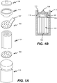
- Figures 1A and 1B are graphical representations of the main components of a cylindrical power cell according to an embodiment of the invention, with Figure 1A showing an exploded view of the cell.
- Alternating electrode and electrolyte (separator) layers are provided in a cylindrical assembly 101 (also called a "jellyroll").
- the cylindrical assembly or jellyroll 101 is positioned inside a can 113 or other containment vessel.
- a negative collector disk 103 and a positive collector disk 105 are attached to opposite ends of cylindrical assembly 101.
- the negative and positive collector disks function as internal terminals, with the negative collector disk electrically connected to the negative electrode and the positive collector disk electrically connected to the positive electrode.
- a cap 109 and the can 113 serve as external terminals.
- negative collector disk 103 includes a tab 107 for connecting the negative collector disk 103 to cap 109.
- Positive collector disk 105 is welded or otherwise electrically connected to can 113.
- the negative collector disk connects to the can and the positive collector disk connects to the cap.
- the negative and positive collector disks 103 and 105 are shown with perforations, which may be employed to facilitate bonding to the jellyroll and/or passage of electrolyte from one portion of a cell to another.
- the disks may employ slots (radial or peripheral), grooves, or other structures to facilitate bonding and/or electrolyte distribution.
- a flexible gasket 111 rests on a circumferential bead 115 provided along the perimeter in the upper portion of can 113, proximate to the cap 109.
- the gasket 111 serves to electrically isolate cap 109 from can 113.
- the bead 115 on which gasket 111 rests is coated with a polymer coating.
- the gasket may be made from any material that electrically isolates the cap from the can. Preferably the material does not appreciably distort at high temperatures; one such material is nylon. In other embodiments, it may be desirable to use a relatively hydrophobic material to reduce the driving force that causes the alkaline electrolyte to creep and ultimately leak from the cell at seams or other available egress points.
- An example of a less wettable material is polypropylene.
- the vessel is sealed to isolate the electrodes and electrolyte from the environment as shown in Figure 1B .
- the gasket is typically sealed by a crimping process.
- a sealing agent is used to prevent leakage.
- suitable sealing agents include bituminous sealing agents, tar and VERSAMID® available from Cognis of Cincinnati, OH.
- the cell is configured to operate in an electrolyte "starved" condition.
- a nickel-zinc cells of this invention employ a starved electrolyte format.
- Such cells have relatively low quantities electrolyte in relation to the amount of active electrode material. They can be easily distinguished from flooded cells, which have free liquid electrolyte in interior regions of the cell.
- a starved cell is generally understood to be one in which the total void volume within the cell electrode stack is not fully occupied by electrolyte.
- the void volume of a starved cell after electrolyte fill may be at least about 10% of the total void volume before fill.
- the battery cells of this invention can have any of a number of different shapes and sizes.
- cylindrical cells of this invention may have the diameter and length of conventional AAA cells, AA cells, A cells, C cells, etc. Custom cell designs are appropriate in some applications.
- the cell size is a sub-C cell size of diameter 22 mm and length 43 mm.
- the present invention also may be employed in relatively small prismatic cell formats, as well as various larger format cells employed for various non-portable applications. Often the profile of a battery pack for, e.g., a power tool or lawn tool will dictate the size and shape of the battery cells.
- This invention also pertains to battery packs including one or more nickel-zinc battery cells of this invention and appropriate casing, contacts, and conductive lines to permit charge and discharge in an electric device.
- the embodiment shown in Figures 1A and 1B has a polarity reverse of that in a conventional nickel-cadmium cell, in that the cap is negative and the can is positive.
- the polarity of the cell is such that the cap is positive and the can or vessel is negative. That is, the positive electrode of the cell assembly is electrically connected with the cap and the negative electrode of the cell assembly is electrically connected with the can that retains the cell assembly.
- the polarity of the cell is opposite of that of a conventional cell.
- the negative electrode is electrically connected with the cap and the positive electrode is electrically connected to the can. It should be understood that in certain embodiments of this invention, the polarity remains the same as in conventional designs - with a positive cap.
- the can is the vessel serving as the outer housing or casing of the final cell.
- the can In conventional cells, where the can is the negative terminal, it is typically nickel-plated steel.
- the can may be either the negative or positive terminal.
- the can material may be of a composition similar to that employed in a conventional nickel cadmium battery, such as steel, as long as the material is coated with another material compatible with the potential of the zinc electrode.
- a negative can may be coated with a material such as copper to prevent corrosion.
- the can may be a composition similar to that used in convention nickel-cadmium cells, typically nickel-plated steel.
- the interior of the can may be coated with a material to aid hydrogen recombination.
- a material to aid hydrogen recombination Any material that catalyzes hydrogen recombination may be used.
- An example of such a material is silver oxide.
- the cell is generally sealed from the environment, the cell may be permitted to vent gases from the battery that are generated during charge and discharge.
- a typical nickel cadmium cell vents gas at pressures of approximately 200 Pounds per Square Inch (PSI).
- PSI Pounds per Square Inch
- a nickel zinc cell is designed to operate at this pressure and even higher (e.g., up to about 300 PSI) without the need to vent. This may encourage recombination of any oxygen and hydrogen generated within the cell.
- the cell is constructed to maintain an internal pressure of up to about 450 PI and or even up to about 600 PSI.
- a nickel zinc cell is designed to vent gas at relatively lower pressures. This may be appropriate when the design encourages controlled release of hydrogen and/or oxygen gases without their recombination within the cell.
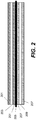
- FIG. 2 illustrates layers in the negative electrode-separator-positive electrode sandwich structure which may be used in a jellyroll or prismatic cell structure.
- the separator 205 mechanically and electrically separates the negative electrode (components 201 and 203) from the positive electrode (components 207 and 209) while allowing ionic current to flow between the electrodes.
- the negative electrode includes electrochemically active layers 201 and an electrode substrate 203.
- the electrochemically active layers 201 of the zinc negative electrode typically include zinc oxide and/or zinc metal as the electrochemically active material.
- the layer 201 may also include other additives or electrochemically active compounds such as calcium zincate, bismuth oxide, aluminum oxide, indium oxide, hydroxyethyl cellulose, and a dispersant.
- the composition of zinc negative electrodes in accordance with certain embodiments will be described in more detail below.
- the negative electrode substrate 203 should be electrochemically compatible with the negative electrode materials 201.
- the electrode substrate may have the structure of a perforated metal sheet, an expanded metal, a metal foam, or a patterned continuous metal sheet.
- the substrate is simply a metal layer such as a metal foil.
- the positive electrode Opposite from the negative electrode on the other side of the separator 205 is the positive electrode.
- the positive electrode also includes electrochemically active layers 207 and an electrode substrate 209.
- the layers 207 of the positive electrode may include nickel hydroxide, nickel oxide, and/or nickel oxyhydroxide as electrochemically active materials and various additives, all of which are described herein.
- the electrode substrate 209 may be, for example, a nickel metal foam matrix or nickel metal sheets. Note that if a nickel foam matrix is used, then layers 907 would form one continuous electrode.
- a separator will have small pores.
- the separator includes multiple layers.
- the pores and/or laminate structure may provide a tortuous path for zinc dendrites and therefore effectively bar penetration and shorting by dendrites.
- the porous separator has a tortuosity of between about 1.5 and 10, more preferably between about 2 and 5.
- the average pore diameter is preferably at most about 0.2 microns, and more preferably between about 0.02 and 0.1 microns.
- the pore size is preferably fairly uniform in the separator.
- the separator has a porosity of between about 35 and 55% with one preferred material having 45% porosity and a pore size of 0.1 micron.
- the separator comprises at least two layers (and preferably exactly two layers) - a barrier layer to block zinc penetration and a wetting layer to keep the cell wet with electrolyte, allowing ionic current to flow. This is generally not the case with nickel cadmium cells, which employ only a single separator material between adjacent electrode layers.
- Performance of the cell may be aided by keeping the positive electrode wet and the negative electrode relatively dry.
- the barrier layer is located adjacent to the negative electrode and the wetting layer is located adjacent to the positive electrode. This arrangement improves performance of the cell by maintaining electrolyte in intimate contact with the positive electrode.
- the wetting layer is placed adjacent to the negative electrode and the barrier layer is placed adjacent to the positive electrode. This arrangement aids recombination of oxygen at the negative electrode by facilitating oxygen transport to the negative electrode via the electrolyte.
- the barrier layer is typically a microporous membrane. Any microporous membrane that is ionically conductive may be used. Often a polyolefin having a porosity of between about 30 and 80 per cent, and an average pore size of between about 0.005 and 0.3 micron will be suitable. In a preferred embodiment, the barrier layer is a microporous polypropylene. The barrier layer is typically about 0.5 - 4 mils thick, more preferably between about 1 and 3 mils thick.
- the wetting layer may be made of any suitable wettable separator material.
- the wetting layer has a relatively high porosity e.g., between about 50 and 85% porosity.
- examples include polyamide materials such as nylon-based as well as wettable polyethylene and polypropylene materials.
- the wetting layer is between about 1 and 10 mils thick, more preferably between about 3 and 6 mils thick.
- Examples of separate materials that may be employed as the wetting material include NKK VL100 (NKK Corporation, Tokyo, Japan), Freudenberg FS2213E, Scimat 650/45 (SciMAT Limited, Swindon, UK), and Vilene FV4365.
- nylon-based materials and microporous polyolefins are very often suitable.
- the separator serves as a "bag" for one of the electrode sheets, effectively encapsulating an electrode layer.
- encapsulating the negative electrode in a separator layer will aid in preventing dendrite formation.
- use of a barrier layer sheet without encapsulating an electrode is sufficient protection against dendrite penetration.
- the electrolyte composition limits dendrite formation and other forms of material redistribution in the zinc electrode.
- suitable electrolytes are described in U.S. Patent No. 5,215,836 issued to M. Eisenberg on June 1, 1993 .
- the electrolyte includes (1) an alkali or earth alkali hydroxide, (2) a soluble alkali or earth alkali fluoride, and (3) a borate, arsenate, and/or phosphate salt (e.g., potassium borate, potassium metaborate, sodium borate, sodium metaborate, and/or a sodium or potassium phosphate).
- the electrolyte comprises about 4.5 to 10 equiv/liter of potassium hydroxide, from about 2 to 6 equiv/liter boric acid or sodium metaborate and from about 0.01 to 1 equivalents of potassium fluoride.
- a specific preferred electrolyte for high rate applications comprises about 8.5 equiv/liter of hydroxide, about 4.5 equivalents of boric acid and about 0.2 equivalents of potassium fluoride.
- the invention is not limited to the electrolyte compositions presented in the Eisenberg patent. Generally, any electrolyte composition meeting the criteria specified for the applications of interest will suffice. Assuming that high power applications are desired, then the electrolyte should have very good conductivity. Assuming that long cycle life is desired, then the electrolyte should resist dendrite formation. In the present invention, the use of borate and/or fluoride containing KOH electrolyte along with appropriate separator layers reduces the formation of dendrites thus achieving a more robust and long-lived power cell.
- the electrolyte composition includes an excess of between about 3 and 5 equiv/liter hydroxide (e.g., KOH, NaOH, and/or LiOH).
- KOH equiv/liter hydroxide
- NaOH equiv/liter hydroxide
- LiOH equiv/liter hydroxide
- an appropriate electrolyte for calcium zincate has the following composition: about 15 to 25% by weight KOH, about 0.5 to 5.0% by weight LiOH.
- the electrolyte may comprise a liquid and a gel.
- the gel electrolyte may comprise a thickening agent such as CARBOPOL® available from Noveon of Cleveland, OH.
- a fraction of the active electrolyte material is in gel form.
- about 5-25% by weight of the electrolyte is provided as gel and the gel component comprises about 1-2% by weight CARBOPOL®.
- the electrolyte may contain a relatively high concentration of phosphate ion as discussed in previous referenced US Patent Publication No. US20060127761 .
- the negative electrode includes one or more electroactive sources of zinc or zincate ions optionally in combination with one or more additional materials such as conductivity enhancing materials, corrosion inhibitors, wetting agents, etc. as described below.
- additional materials such as conductivity enhancing materials, corrosion inhibitors, wetting agents, etc.
- the electrode When the electrode is fabricated it will be characterized by certain physical, chemical, and morphological features such as coulombic capacity, chemical composition of the active zinc, porosity, tortuosity, etc.
- the electrochemically active zinc source may include one or more of the following components: zinc oxide, calcium zincate, zinc metal, and various zinc alloys. Any of these materials may be provided during fabrication and/or be created during normal cell cycling. As a particular example, consider calcium zincate, which may be produced from a paste or slurry containing, e.g., calcium oxide and zinc oxide. Metallic zinc particles may create and maintain a conductive matrix during cycling.
- a zinc alloy may in certain embodiments include bismuth and/or indium. In certain embodiments, it may include up to about 20 parts per million lead and in other embodiments up to about 10 parts per million lead.
- a commercially available source of zinc alloy meeting this composition requirement is PG101 provided by Noranda Corporation of Canada.
- the zinc active material exists in the form of a powder particles which are less than 100 microns in size.
- each of the components employed in a zinc electrode paste formulation has a relatively small particle size. This is to reduce the likelihood that a particle may penetrate or otherwise damage the separator between the positive and negative electrodes.
- the negative electrode may include one or more additional materials that facilitate or otherwise impact certain processes within the electrode such as ion transport, electron transport (e.g., the material enhances conductivity), wetting, porosity, structural integrity (e.g., binding), gassing, active material solubility, barrier properties (e.g., reducing the amount of zinc leaving the electrode), corrosion inhibition etc.
- additional materials that facilitate or otherwise impact certain processes within the electrode such as ion transport, electron transport (e.g., the material enhances conductivity), wetting, porosity, structural integrity (e.g., binding), gassing, active material solubility, barrier properties (e.g., reducing the amount of zinc leaving the electrode), corrosion inhibition etc.
- the negative electrode includes an oxide such as bismuth oxide, indium oxide, and/or aluminum oxide.
- Bismuth oxide and indium oxide may interact with zinc and reduce gassing at the electrode.
- Bismuth oxide may be provided in a concentration of between about 1 and 10% by weight of a dry negative electrode formulation. It may facilitate recombination of hydrogen and oxygen.
- Indium oxide may be present in a concentration of between about 0.05 and 1% by weight of a dry negative electrode formulation.
- Aluminum oxide may be provided in a concentration of between about 1 and 5% by weight of a dry negative electrode formulation.
- one or more additives may be included to improve corrosion resistance of the zinc electroactive material and thereby facilitate long shelf life.
- the shelf life can be critical to the commercial success or failure of a battery cell. Recognizing that batteries are intrinsically chemically unstable devices, steps may be taken to preserve battery components, including the negative electrode, in their chemically useful form. When electrode materials corrode or otherwise degrade to a significant extent over weeks or months without use, their value becomes limited by short shelf life. The inventors have found that an addition of small amounts of lead and tin is very effective to improve zinc corrosion resistance.
- Chireau et al. in US patent 4,118,551 discusses the use of salts of lead and cadmium to reduce corrosion of zinc.
- the present method of adding lead and/or tin not only reduces corrosion of zinc, but also improves the cycle life and stability of the fabrication mixture (e.g., a slurry or paste) for making the negative electrode. This is accomplished with a much lower amount of lead than that disclosed in Chireau. In the present method, typical lead addition is only 0.02% by weight, where as in Chireau, the amount is about 1% by weight.
- the zinc negative electrode is made by first treating zinc particles, mixing the remaining paste ingredients, and incorporating the paste into a zinc electrode.
- Lead and/or tin are coated onto the zinc particles in the first step.
- a soluble source of lead and/or a soluble source of tin is added to zinc particles in a liquid medium, preferably water.
- a binding agent and a dispersant are added too to create a coated zinc particle slurry.
- the soluble lead may be one or more of lead acetate, lead chloride, lead fluoborate, and lead nitrate.
- the soluble tin may be one or more of tin sulfate, tin acetate, tin chloride, tin fluoborate, and tin nitrate.
- the soluble lead and tin may be added together in a premix or added separately, in powder form or pre-dissolved.
- the coated zinc particles are obtained pre-made and the inventive process dispenses with the initial treatment operation.
- the uncoated zinc metal (or zinc alloy) powder particles used in the negative electrode are less than 40 microns in size, or less than about 25 microns in size, or about 5-15 microns in size. In some cases, they may be selected by size by passing through a sieve. Thus, the "size" of a zinc particle may often be viewed as the minimum dimension of the particles, as the particles may have many different shapes and aspect ratios.
- Suitable zinc alloy particles include zinc alloys of lead, bismuth, and indium.
- the zinc metal particles may be completely or partially coated.
- the lead coating may be less than about 0.25% percent by weight of the coated zinc particle.
- the tin coating may be less than about 5% percent by weight of the coated particle.
- the zinc metal particles may be 5-30% or about 20% of the dry paste by weight.
- the lead concentration in the dry paste may be less about 0.08% or less than about 0.05%, and the tin coating less than about 1.5% or less than about 1% in the dry paste by weight.
- the remaining zinc electrode constituents may be mixed into the slurry or paste. Note that some dissolved lead and tin salt may remain in the slurry.
- the remaining zinc electrode constituents include zinc oxide, and optionally bismuth oxide, alumina, indium, and potassium fluoride or calcium. More zinc particles may be added at this stage. These remaining zinc electrode constituents may be premixed in a powder form.
- a negative paste or slurry is thus formed and is used to coat the negative electrode substrate.
- the lead is preferably between 0% and about 0.05% by weight.
- the tin is preferably between 0% and about 1% by weight.
- the agglomeration reduction process involves mixing the binding agent, dispersant, and lead acetate together first for, e.g., about 5 minutes in a mixer.
- the binding agent may be a hydroxy-ethyl cellulose.
- the dispersant may be a commercially available oxide dispersant such as Nopcosperse available from San Nopco Ltd. of Kyoto Japan. After this initial mixing, the remainder of the zinc electrode constituent is added to the mixer in a pre-mixed powder form.
- the remaining constituent may include zinc oxide, zinc powder, alumina, bismuth oxide, indium, potassium fluoride or calcium. These ingredients are mixed at a high rpm (e.g., over 2000) for about 5 minutes. Lastly, a pre-dissolved tin salt, e.g., tin sulfate, is added slowly to the mixture. The entire batch may be further mixed for up to 25 minutes. In this anti-agglomeration process, the dissolved tin salt may not coat the zinc particle as much as if it were added earlier. The lead deposit therefore may account for the redox potential.
- tin salt e.g., tin sulfate
- the first mixture may include soluble tin acetate without the zinc particles, which is added in the bulk mixing step. It is believed that the zinc particles are adequately coated with lead and/or tin even when they are added with other constituents.
- one mode of corrosion mitigation is having the lead and tin available to alloy with cobalt wherein the resulting alloy is less catalytic in the zinc corrosion reaction.
- Another mode of corrosion mitigation is the physical coating of the zinc particle and rendering its surfaces unavailable for the corrosion reaction. Note that the zinc particle coating operation is not believed to create a zinc alloy with lead or tin. The reaction appears to be a displacement reaction on the zinc particle surface.
- anions that may be included to reduce the solubility of zinc in the electrolyte include phosphate, fluoride, borate, zincate, silicate, stearate, etc.
- these anions may be present in a negative electrode in concentrations of up to about 5% by weight of a dry negative electrode formulation. It is believed that at least certain of these anions go into solution during cell cycling and there they reduce the solubility of zinc. Examples of electrode formulations including these materials are included in the following patents and patent applications: U.S. Patent No.
- Examples of materials that may be added to the negative electrode to improve wetting include titanium oxides, alumina, silica, alumina and silica together, etc. Generally, these materials are provided in concentrations of up to about 10% by weight of a dry negative electrode formulation. A further discussion of such materials may be found in U.S. Patent No. 6,811,926, issued November 2, 2004 , titled, "Formulation of Zinc Negative Electrode for Rechargeable Cells Having an Alkaline Electrolyte,” by Jeffrey Phillips.
- Examples of materials that may be added to the negative electrode to improve electronic conductance include various electrode compatible materials having high intrinsic electronic conductivity. Examples include titanium oxides, etc. Generally, these materials are provided in concentrations of up to about 10% by weight of a dry negative electrode formulation. The exact concentration will depend, of course, on the properties of chosen additive.
- organic materials may be added to the negative electrode for the purpose of binding, dispersion, and/or as surrogates for separators.
- examples include hydroxylethyl cellulose (HEC), carboxymethyl cellulose (CMC), the free acid form of carboxymethyl cellulose (HCMC), polytetrafluoroethylene (PTFE), polystyrene sulfonate (PSS), polyvinyl alcohol (PVA), nopcosperse dispersants (available from San Nopco Ltd. of Kyoto Japan), etc.
- HEC hydroxylethyl cellulose
- CMC carboxymethyl cellulose
- HCMC free acid form of carboxymethyl cellulose
- PTFE polytetrafluoroethylene
- PSS polystyrene sulfonate
- PVA polyvinyl alcohol
- nopcosperse dispersants available from San Nopco Ltd. of Kyoto Japan
- polymeric materials such as PSS and PVA may be mixed with the paste formation (as opposed to coating) for the purpose of burying sharp or large particles in the electrode that might otherwise pose a danger to the separator.
- an electrode composition when defining an electrode composition herein, it is generally understood as being applicable to the composition as produced at the time of fabrication (e.g., the composition of a paste, slurry, or dry fabrication formulation), as well as compositions that might result during or after formation cycling or during or after one or more charge-discharge cycles while the cell is in use such as while powering a portable tool.
- Negative electrode additives in the above references include, for example, silica and fluorides of various alkaline earth metals, transition metals, heavy metals, and noble metals.
- the nickel hydroxide electrode has been used as the positive electrode in high power and high energy nickel-metal hydride batteries, nickel-cadmium batteries and nickel-zinc batteries.
- the pasted nickel hydroxide electrode typically includes nickel hydroxide particles, cobalt/cobalt compound powder particles, nickel powder and binding materials.
- the cobalt compound is included to increase the conductivity of the nickel electrode. However, as explained, the same cobalt compound causes detrimental effects if it migrates to the zinc negative electrode.
- the positive electrode formulation may include nickel oxide particles and cobalt.
- a nickel foam matrix is preferably used to support the electro-active nickel oxide (e.g., Ni(OH) 2 ) electrode material.
- the foam substrate thickness may be may be between 15 and 60 mils (0.39-1.5 mm).
- the thickness of the positive electrode, comprising nickel foam filled with the electrochemically active and other electrode materials ranges from about 16 - 24 mils (0.41-0.61 mm), preferably about 20 mils thick (0.51 mm).
- a nickel foam density of about 350 g/m 2 and thickness ranging from about 16 - 18 mils (0.41-0.46 mm) is used.
- the positive electrode generally includes an electrochemically active nickel oxide or hydroxide and one or more additives to facilitate manufacturing, electron transport, wetting, mechanical properties, etc.
- a positive electrode formulation may include nickel hydroxide particles, zinc oxide, cobalt oxide (CoO), cobalt metal, nickel metal, and a thixotropic agent such as carboxymethyl cellulose (CMC).
- CMC carboxymethyl cellulose
- the metallic nickel and cobalt may be chemically pure or alloys.
- the positive electrode may be made from paste containing these materials and binder such as Teflon suspension.
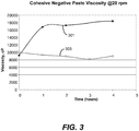
- Composition 1 (shown as 103 in Figure 1 ) is referred to as Cohesive w/PbAc-SnSO 4 and contains 3000 parts by weight of ZnO, 97 parts by weight of Bi 2 O 3 , 20 parts by weight of hydroxy-ethyl cellulose, 2100 parts by weight water, 240 parts by weight of a slurry containing 60% Teflon binder, 600 parts by weight metallic zinc powder, 1.4 parts lead salt containing 55% lead and 40 parts tin salt containing 55% tin.
- Composition 2 (shown as 101 in Figure 1 ) is called the Cohesive Control. It is identical to Composition 1 without any tin and lead added.
- Figure 3 compares the stability of the viscosity over time for these two compositions, as the slurry was mildly stirred at 20 rpm. As shown, composition 2 (line 303) maintained its viscosity much better than the control. The two compositions started with very similar viscosities; however, for the control paste 301, viscosity increased significantly during the first hour and stayed fairly constant. The increased viscosity after only one hour reduces the ability for the paste to be worked after one hour and reduces manufacturability.
- Standard sub-C size cells were made with negative pastes with various concentrations of tin and lead and keeping all other components the same.
- the cells employed an electrolyte having a composition of 760g H 2 O, 1220g 45% potassium hydroxide solution, 84.7g sodium phosphate (Na 3 PO 4 ⁇ 12H 2 O), 59g Sodium hydroxide, 16.8g Lithium hydroxide, 3.2g Zinc oxide (ZnO).
- a microporous 50 micron separator manufactured by UBE and a cellulose - polyvinyl alcohol wicking separator were used in between the two electrodes.
- the cells were then tested for cycling and gassing reduction.
- the positive electrodes were prepared with nickel hydroxide that included a cobalt (III) coated layer that provided inter-particle conductivity. Cobalt metal powder (2%) and nickel powder (9%) was added to the positive paste mix to provide additional conductivity for high discharge rate capability. During the 1-2 hour soak times that exist between filling the cell and the application of the first formation charge the added cobalt can dissolve and migrate to the negative electrode.
- Formation of cells refers to the initial electrical charging. Each cell was charged at 91mA for 20.5 hrs and discharged at 1A to 1.0V. Then they were charged at 0.1A for 18 hrs and at 0.075A for 6.5 hrs.
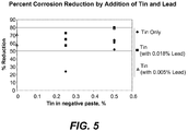
- Negative containing lead Cell Gassing: Lead Acetate Added to Negative Paste Group Description Composition Gassing Rate % Gassing Reduction Added % Pb % Sn cc/day 83501 - Control 0 0 4.38 57.53 83507 - Pb Acetate 0.05 0 1.86 84502 - Control 0 0 4.00 71.25 84503 - Pb Acetate 0.05 0 1.15 Zn+2OH(-) ⁇ ZnO 2 (2-)+ H 2
- Table 1 shows the test results for two sets of comparisons. In both sets, a control cell and a cell containing 0.05% lead in the negative paste are compared. The lead in the negative electrode is added by coating the zinc particles with lead acetate. In one set, the gassing was reduced by 58%. In another, the gassing was reduced by 71%. Table 2. A Comparison of Cell Gassing Rates (Control Cell vs.
- Negative containing tin Cell Gassing:Tin Sulfate Added to Negative Paste Group Description Composition Gassing Rate % Gassing Reduction Added % Pb % Sn cc/day 83601 - Control 0 0 3.55 78.87 83606 - SnSO4 0 0.507 0.75 84302 - Control 0 0 3.80 60.53 84304 - SnSO4 0 0.507 1.50 84901 - Control 0 0 7.30 52.05 84902 - SnSO4 0 0.507 3.50 85201 - Control 0 0 9.40 63.83 85202 - SnSO4 0 0.507 3.40 90101 - Control 0 0 12.23 63.21 90103 - SnSO4 0 0.507 4.50 90501 - Control 0 0 8.85 23.73 90502 - SnSO4 0 0.254 6.75
- Table 2 Six sets of comparisons were made in Table 2. In these sets, a control cell and a cell containing tin in the negative electrode are compared. The tin in the negative electrode is added by coating the zinc particles with tin sulfate. In five sets, the negative paste contained 0.5% tin. In one set, the negative paste contained 0.25% tin. The results show a gassing reduction between about 50-80% for the higher tin concentration cell and a 24% reduction for the lower tin concentration cell. According to Table 2, more tin coating improves zinc corrosion mitigation. Table 3. A Comparison of Cell Gassing Rates (Control vs.
- Negative containing tin & lead Cell Gassing: Lead Acetate/Tin Sulfate Added to Negative Paste Group Description Composition Added % Pb % Sn Gassing Rate cc/day % Gassing Reduction 90601 - Control 0 0 6.95 90602A - Pb Acetate / SnSO4 0.050 0.507 1.45 79.14 90701 - Control 0 0 7.95 90702 - Pb Acetate / SnSO4 0.018 0.254 3.40 57.23 90801 - Control 0 0 6.40 90802A - Pb Acetate / SnSO4 0.018 0.254 2.25 64.84 90901 - Control 0 0 8.80 90902A - Pb Acetate / Sn Acetate 0.018 0.231 2.40 72.73 91143B - Control 0 0 8.90 91101 - Pb Acetate / SnSO4 0.018 0.254 3.10 65
- Table 3 shows 5 sets of data for various combinations of lead and tin concentrations. Two levels of lead and approximately two levels of tin were compared with no lead or tin. In every case significant gassing reductions were achieved. The best gassing reductions were found at the tin sulfate level of 0.5%, with the lead concentration either at 0.05% or 0.018%. Note that the low level of lead used in these cells is below the level forbidden by RoHS' environmental standard (Restriction of Hazardous Substances Directive prohibits the use of lead above 1000 ppm in an homogeneous material). However, this small amount of lead coating (about 400 ppm or less) is beneficial against zinc corrosion. Results from Tables 1-3 are also summarized in Figure 5 .
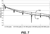
- Figures 6A, 6B , and 7 are examples of improvement in cycling of cells built with the addition of lead and tin individually and then combination of the two. They are then compared with control cells referring to cells with no addition of tin and lead. In each case, it is shown that the cycle life is improved.
- Figure 6A compares the control cell (plotted as line 403) and the cell made with lead coated zinc particles (line 401), with lead at 0.05%. Both cells behaved similarly until about cycle 150. The cell with lead coated zinc lasted longer a more consistent discharge capacity. The control cell failed earlier and deteriorated at a much faster rate.
- Figure 6B compares a control cell (407) and a cell made with tin coated zinc particles (405).
- the tin concentration was 0.507%, from tin sulfate.
- the cell with tin coated zinc (405) lasted longer. Its capacity also decreased slower, though the cell with tin coated zinc (405) appears to have a slightly lower initial discharge capacity.
- Figure 7 compares a control cell and a cell having 0.018% lead and 0.254% tin in the negative electrode paste. In this comparison, the cell with tin and lead coated zinc particles consistently has higher discharge capacity. These figures show that cycling performance is improved by coating the zinc particles with lead or lead and tin.
- the effect of the additives appears to be in mitigating the catalytic effect of cobalt contamination of the negative electrode. While this is expected to be most beneficial to pasted positive electrodes where either cobalt metal or cobalt (II) oxide is added to the paste there is also expected to be a benefit in nickel zinc cells where cobalt is primarily present as cobalt (III) on the surface of the nickel hydroxide particles. Even though this material should be relatively insoluble in alkaline electrolytes there appears to be some migration of the cobalt to the negative after several hours of soaking. In these cases it is suspected that the either the surface cobalt may not be fully oxidized or that it has been reduced over time to soluble cobalt (II) oxide by other materials in the positive paste.
Landscapes
- Chemical & Material Sciences (AREA)
- Chemical Kinetics & Catalysis (AREA)
- Electrochemistry (AREA)
- General Chemical & Material Sciences (AREA)
- Engineering & Computer Science (AREA)
- Manufacturing & Machinery (AREA)
- Dispersion Chemistry (AREA)
- Materials Engineering (AREA)
- Battery Electrode And Active Subsutance (AREA)
- Powder Metallurgy (AREA)
- Secondary Cells (AREA)
Applications Claiming Priority (2)
| Application Number | Priority Date | Filing Date | Title |
|---|---|---|---|
| US12/467,993 US8501351B2 (en) | 2009-05-18 | 2009-05-18 | Pasted zinc electrode for rechargeable nickel-zinc batteries |
| PCT/US2010/035266 WO2010135331A1 (en) | 2009-05-18 | 2010-05-18 | Pasted zinc electrode for rechargeable zinc batteries |
Publications (2)
| Publication Number | Publication Date |
|---|---|
| EP2433325A1 EP2433325A1 (en) | 2012-03-28 |
| EP2433325B1 true EP2433325B1 (en) | 2019-04-24 |
Family
ID=42358303
Family Applications (1)
| Application Number | Title | Priority Date | Filing Date |
|---|---|---|---|
| EP10724181.2A Active EP2433325B1 (en) | 2009-05-18 | 2010-05-18 | Pasted zinc electrode for rechargeable zinc batteries |
Country Status (6)
| Country | Link |
|---|---|
| US (2) | US8501351B2 (enExample) |
| EP (1) | EP2433325B1 (enExample) |
| JP (1) | JP5771193B2 (enExample) |
| KR (1) | KR101769630B1 (enExample) |
| CN (1) | CN102439764B (enExample) |
| WO (1) | WO2010135331A1 (enExample) |
Families Citing this family (42)
| Publication number | Priority date | Publication date | Assignee | Title |
|---|---|---|---|---|
| US20080057386A1 (en) | 2002-10-15 | 2008-03-06 | Polyplus Battery Company | Ionically conductive membranes for protection of active metal anodes and battery cells |
| US7645543B2 (en) | 2002-10-15 | 2010-01-12 | Polyplus Battery Company | Active metal/aqueous electrochemical cells and systems |
| EP1661195B1 (en) * | 2003-08-18 | 2016-01-13 | PowerGenix Systems, Inc. | Method of manufacturing nickel zinc batteries |
| US20080166632A1 (en) * | 2003-08-18 | 2008-07-10 | Powergenix, Inc. | Method of manufacturing nickel zinc batteries |
| US9368775B2 (en) | 2004-02-06 | 2016-06-14 | Polyplus Battery Company | Protected lithium electrodes having porous ceramic separators, including an integrated structure of porous and dense Li ion conducting garnet solid electrolyte layers |
| US7282295B2 (en) | 2004-02-06 | 2007-10-16 | Polyplus Battery Company | Protected active metal electrode and battery cell structures with non-aqueous interlayer architecture |
| US8703330B2 (en) * | 2005-04-26 | 2014-04-22 | Powergenix Systems, Inc. | Nickel zinc battery design |
| EP2272124B1 (en) * | 2008-04-02 | 2016-03-23 | PowerGenix Systems, Inc. | Cylindrical nickel-zinc cell with negative can |
| EP2301105A4 (en) | 2008-06-16 | 2013-06-19 | Polyplus Battery Co Inc | AQUEOUS LITHIUM / AIR BATTERY CELLS |
| US8501351B2 (en) | 2009-05-18 | 2013-08-06 | Powergenix Systems, Inc. | Pasted zinc electrode for rechargeable nickel-zinc batteries |
| EP2476156B1 (en) | 2009-09-08 | 2017-04-05 | Powergenix Systems, Inc. | Selective heat sealing of separators for nickel zinc cells |
| WO2011047105A1 (en) * | 2009-10-14 | 2011-04-21 | Research Foundation Of The City University Of New York | Nickel-zinc flow battery |
| CN102544453A (zh) * | 2010-12-17 | 2012-07-04 | 广州市云通磁电有限公司 | 一种镍氢动力电池专用正极制造方法 |
| US20140205909A1 (en) * | 2011-08-23 | 2014-07-24 | Nippon Shokubai Co., Ltd. | Negative electrode mixture or gel electrolyte, and battery using said negative electrode mixture or said gel electrolyte |
| JP6246999B2 (ja) * | 2011-08-23 | 2017-12-13 | 株式会社日本触媒 | 亜鉛負極合剤及び該亜鉛負極合剤を使用した電池 |
| US9660265B2 (en) | 2011-11-15 | 2017-05-23 | Polyplus Battery Company | Lithium sulfur batteries and electrolytes and sulfur cathodes thereof |
| US9337683B2 (en) | 2012-12-20 | 2016-05-10 | Powergenix Systems, Inc. | Controlling battery states of charge in systems having separate power sources |
| EP2822087A1 (en) * | 2013-07-02 | 2015-01-07 | Hangzhou Neucell Energy Co., Ltd. | Nickel-zinc battery assembly and manufacturing method thereof |
| CN103346283A (zh) * | 2013-07-02 | 2013-10-09 | 杭州新研动力能源有限公司 | 一种镍锌电池的保护方法 |
| JP6576462B2 (ja) * | 2015-11-06 | 2019-09-18 | 日産自動車株式会社 | 二次電池用亜鉛負極材 |
| WO2017092981A1 (de) * | 2015-12-03 | 2017-06-08 | Varta Microbattery Gmbh | Zur herstellung einer anode geeignete metallpartikel, herstellung einer anode, hergestellte anode und elektrochemische zelle mit der hergestellten anode |
| CN109964345B (zh) * | 2016-12-28 | 2022-11-04 | 松下知识产权经营株式会社 | 非水电解质二次电池用正极及非水电解质二次电池 |
| CN106935865B (zh) * | 2017-05-12 | 2023-04-18 | 中塑新材料技术(吉林)有限公司 | 一种电池负极及其制备方法、锌镍电池 |
| KR102048400B1 (ko) * | 2017-12-13 | 2019-11-25 | 재단법인 포항산업과학연구원 | 이중 충진구조를 갖는 니켈-아연 이차전지용 음극 |
| CN110364660B (zh) * | 2018-04-10 | 2022-07-15 | 浙江浙能中科储能科技有限公司 | 一种水系锌离子电池复合隔膜及制备方法 |
| KR20210035302A (ko) * | 2018-08-14 | 2021-03-31 | 샐리언트 에너지 인크. | 충전식 아연 셀 및 배터리를 위한 보호된 아연 금속 전극 및 방법 |
| JP7566452B2 (ja) * | 2018-11-19 | 2024-10-15 | エナジーウィズ株式会社 | 亜鉛電池 |
| CN110755200B (zh) * | 2019-10-08 | 2022-07-22 | 东华大学 | 一种Ag/Zn微电流医用敷料的制备方法 |
| CN111146431B (zh) * | 2020-02-11 | 2022-11-29 | 河南创力新能源科技股份有限公司 | 一种铁镍电池负极复合材料及其制备方法 |
| CN111463408A (zh) * | 2020-03-18 | 2020-07-28 | 山东合泰新能源有限公司 | 一种涂布式锌电极制备方法 |
| JP2021158028A (ja) * | 2020-03-27 | 2021-10-07 | 日本碍子株式会社 | 亜鉛二次電池 |
| CN111916744B (zh) * | 2020-07-31 | 2022-03-08 | 中南大学 | 一种锌离子电池液态金属复合负极及其制备方法和应用 |
| WO2022118610A1 (ja) * | 2020-12-03 | 2022-06-09 | 日本碍子株式会社 | 負極及び亜鉛二次電池 |
| CN116391289A (zh) * | 2020-12-03 | 2023-07-04 | 日本碍子株式会社 | 负极及锌二次电池 |
| CN112436203B (zh) * | 2020-12-28 | 2021-12-14 | 中国科学技术大学 | 一种降低锌钴电池自放电的充电方法 |
| CN113140708B (zh) * | 2021-03-22 | 2022-08-19 | 复旦大学 | 一种基于锡负极的碱性蓄电池 |
| US20230074320A1 (en) * | 2021-09-06 | 2023-03-09 | Mohammad Shafikul Huq | System and method for recharagable battery module by combining cells of varying sizes |
| KR102627841B1 (ko) | 2021-12-17 | 2024-01-23 | 한국과학기술연구원 | 아연금속 전극 및 그 제조방법 |
| WO2023225072A1 (en) * | 2022-05-18 | 2023-11-23 | The Regents Of The University Of California | Flow-assisted battery |
| JPWO2024034132A1 (enExample) * | 2022-08-12 | 2024-02-15 | ||
| CN115275201B (zh) * | 2022-08-15 | 2024-07-26 | 中南大学 | 一种半固态锌浆料负极及其制备方法和应用、水系锌离子电池 |
| JP7849853B2 (ja) * | 2023-03-23 | 2026-04-22 | Ngk株式会社 | 負極及び亜鉛二次電池 |
Citations (1)
| Publication number | Priority date | Publication date | Assignee | Title |
|---|---|---|---|---|
| US6787265B2 (en) * | 2000-11-10 | 2004-09-07 | Powergenix Systems, Inc. | Positive and negative interactive electrode formulation for a zinc-containing cell having an alkaline electrolyte |
Family Cites Families (28)
| Publication number | Priority date | Publication date | Assignee | Title |
|---|---|---|---|---|
| JPS5461B2 (enExample) * | 1973-11-21 | 1979-01-05 | ||
| US4118551A (en) | 1977-10-31 | 1978-10-03 | Yardney Electric Corporation | Mercury-free zinc electrode |
| JPS58218761A (ja) | 1982-06-11 | 1983-12-20 | Toshiba Battery Co Ltd | アルカリ電池 |
| JPS59175557A (ja) * | 1983-03-25 | 1984-10-04 | Toshiba Battery Co Ltd | アルカリ電池 |
| JP2562664B2 (ja) * | 1988-06-07 | 1996-12-11 | 三井金属鉱業株式会社 | アルカリ電池およびその負極活物質 |
| US5215836A (en) | 1991-07-18 | 1993-06-01 | Electrochimica Corporation | Alkaline galvanic cells |
| JPH10144313A (ja) | 1996-11-13 | 1998-05-29 | Dowa Mining Co Ltd | アルカリ二次電池 |
| JP3692965B2 (ja) * | 2000-05-15 | 2005-09-07 | 株式会社デンソー | リチウム二次電池およびその正極の製造方法 |
| CA2325791A1 (en) | 2000-11-10 | 2002-05-10 | Jeffrey Phillips | Negative electrode formulation for a low toxicity zinc electrode having additives with redox potentials positive to zinc potential |
| CA2325308A1 (en) | 2000-11-10 | 2002-05-10 | Jeffrey Phillips | Negative electrode formulation for a low toxicity zinc electrode having additives with redox potentials negative to zinc potential |
| CA2377065A1 (en) | 2001-03-15 | 2002-09-15 | Powergenix Systems Inc. | Alkaline cells having low toxicity rechargeable zinc electrodes |
| US7550230B2 (en) | 2001-03-15 | 2009-06-23 | Powergenix Systems, Inc. | Electrolyte composition for nickel-zinc batteries |
| NZ510554A (en) | 2001-03-15 | 2003-08-29 | Univ Massey | Rechargeable zinc electrode comprising a zinc salt and a derivative of a fatty acid or alkyl sulfonic acid |
| US6709788B2 (en) | 2001-05-11 | 2004-03-23 | Denso Corporation | Lithium secondary cell and method of producing lithium nickel metal oxide positive electrode therefor |
| JP4821075B2 (ja) * | 2001-09-04 | 2011-11-24 | 株式会社デンソー | リチウム二次電池用電極及びリチウム二次電池 |
| US7273680B2 (en) * | 2002-08-28 | 2007-09-25 | The Gillette Company | Alkaline battery including nickel oxyhydroxide cathode and zinc anode |
| US7435395B2 (en) * | 2003-01-03 | 2008-10-14 | The Gillette Company | Alkaline cell with flat housing and nickel oxyhydroxide cathode |
| US6991872B2 (en) * | 2003-03-26 | 2006-01-31 | The Gillette Company | End cap seal assembly for an electrochemical cell |
| US20060207084A1 (en) | 2004-08-17 | 2006-09-21 | Powergenix, Inc. | Method of manufacturing nickel zinc batteries |
| EP1661195B1 (en) | 2003-08-18 | 2016-01-13 | PowerGenix Systems, Inc. | Method of manufacturing nickel zinc batteries |
| JP4661059B2 (ja) | 2004-02-23 | 2011-03-30 | パナソニック株式会社 | アルカリ蓄電池とその製造方法 |
| JP3742828B2 (ja) | 2004-05-19 | 2006-02-08 | 三井金属鉱業株式会社 | 非水電解液二次電池用負極 |
| JP2006179430A (ja) * | 2004-12-24 | 2006-07-06 | Matsushita Electric Ind Co Ltd | アルカリ電池用亜鉛合金粉体 |
| EP1859504A2 (en) * | 2005-03-01 | 2007-11-28 | Powergenix Systems, Inc. | Method of manufacturing nickel zinc batteries |
| US8703330B2 (en) | 2005-04-26 | 2014-04-22 | Powergenix Systems, Inc. | Nickel zinc battery design |
| CN101740762B (zh) | 2008-11-25 | 2012-06-06 | 比亚迪股份有限公司 | 锌负极及其制备方法以及使用该锌负极的锌二次电池 |
| US8501351B2 (en) | 2009-05-18 | 2013-08-06 | Powergenix Systems, Inc. | Pasted zinc electrode for rechargeable nickel-zinc batteries |
| KR101839158B1 (ko) * | 2009-10-13 | 2018-03-15 | 파워지닉스 시스템즈, 인코포레이티드 | 양성 캔을 포함하는 원통형 니켈-아연 전지 |
-
2009
- 2009-05-18 US US12/467,993 patent/US8501351B2/en active Active
-
2010
- 2010-05-18 CN CN201080022093.8A patent/CN102439764B/zh active Active
- 2010-05-18 EP EP10724181.2A patent/EP2433325B1/en active Active
- 2010-05-18 JP JP2012511964A patent/JP5771193B2/ja active Active
- 2010-05-18 WO PCT/US2010/035266 patent/WO2010135331A1/en not_active Ceased
- 2010-05-18 KR KR1020117030313A patent/KR101769630B1/ko active Active
-
2013
- 2013-07-10 US US13/938,520 patent/US9048488B2/en active Active
Patent Citations (1)
| Publication number | Priority date | Publication date | Assignee | Title |
|---|---|---|---|---|
| US6787265B2 (en) * | 2000-11-10 | 2004-09-07 | Powergenix Systems, Inc. | Positive and negative interactive electrode formulation for a zinc-containing cell having an alkaline electrolyte |
Also Published As
| Publication number | Publication date |
|---|---|
| JP5771193B2 (ja) | 2015-08-26 |
| WO2010135331A1 (en) | 2010-11-25 |
| US9048488B2 (en) | 2015-06-02 |
| US20100291439A1 (en) | 2010-11-18 |
| KR20120023806A (ko) | 2012-03-13 |
| US20140157586A1 (en) | 2014-06-12 |
| KR101769630B1 (ko) | 2017-08-18 |
| US8501351B2 (en) | 2013-08-06 |
| JP2012527733A (ja) | 2012-11-08 |
| CN102439764B (zh) | 2015-11-25 |
| CN102439764A (zh) | 2012-05-02 |
| EP2433325A1 (en) | 2012-03-28 |
Similar Documents
| Publication | Publication Date | Title |
|---|---|---|
| EP2433325B1 (en) | Pasted zinc electrode for rechargeable zinc batteries | |
| US8043748B2 (en) | Pasted nickel hydroxide electrode for rechargeable nickel-zinc batteries | |
| US8048566B2 (en) | Nickel hydroxide electrode for rechargeable batteries | |
| US8940430B2 (en) | Metallic zinc-based current collector | |
| US9337483B2 (en) | Pasted nickel hydroxide electrode and additives for rechargeable alkaline batteries | |
| Jindra | Sealed nickel—zinc cells | |
| EP1176649A1 (en) | An alkaline secondary battery with an improved positive nickel electrode and procedure for its activation |
Legal Events
| Date | Code | Title | Description |
|---|---|---|---|
| PUAI | Public reference made under article 153(3) epc to a published international application that has entered the european phase |
Free format text: ORIGINAL CODE: 0009012 |
|
| 17P | Request for examination filed |
Effective date: 20111212 |
|
| AK | Designated contracting states |
Kind code of ref document: A1 Designated state(s): AL AT BE BG CH CY CZ DE DK EE ES FI FR GB GR HR HU IE IS IT LI LT LU LV MC MK MT NL NO PL PT RO SE SI SK SM TR |
|
| RIN1 | Information on inventor provided before grant (corrected) |
Inventor name: WU, JAMES, J. Inventor name: PHILLIPS, JEFFREY Inventor name: MOHANTA, SAMARESH Inventor name: BOSE, DEEPAN, CHAKKARAVARTHI Inventor name: MASKE, CECILIA Inventor name: MCKINNEY, BRYAN, L. |
|
| DAX | Request for extension of the european patent (deleted) | ||
| 17Q | First examination report despatched |
Effective date: 20130222 |
|
| RAP1 | Party data changed (applicant data changed or rights of an application transferred) |
Owner name: ZINCFIVE POWER, INC. |
|
| RIC1 | Information provided on ipc code assigned before grant |
Ipc: H01M 10/30 20060101ALI20181003BHEP Ipc: H01M 4/26 20060101ALI20181003BHEP Ipc: H01M 4/04 20060101ALI20181003BHEP Ipc: H01M 4/24 20060101AFI20181003BHEP Ipc: H01M 4/32 20060101ALI20181003BHEP |
|
| GRAP | Despatch of communication of intention to grant a patent |
Free format text: ORIGINAL CODE: EPIDOSNIGR1 |
|
| STAA | Information on the status of an ep patent application or granted ep patent |
Free format text: STATUS: GRANT OF PATENT IS INTENDED |
|
| INTG | Intention to grant announced |
Effective date: 20181114 |
|
| GRAS | Grant fee paid |
Free format text: ORIGINAL CODE: EPIDOSNIGR3 |
|
| GRAA | (expected) grant |
Free format text: ORIGINAL CODE: 0009210 |
|
| STAA | Information on the status of an ep patent application or granted ep patent |
Free format text: STATUS: THE PATENT HAS BEEN GRANTED |
|
| AK | Designated contracting states |
Kind code of ref document: B1 Designated state(s): AL AT BE BG CH CY CZ DE DK EE ES FI FR GB GR HR HU IE IS IT LI LT LU LV MC MK MT NL NO PL PT RO SE SI SK SM TR |
|
| REG | Reference to a national code |
Ref country code: GB Ref legal event code: FG4D |
|
| REG | Reference to a national code |
Ref country code: CH Ref legal event code: EP |
|
| REG | Reference to a national code |
Ref country code: AT Ref legal event code: REF Ref document number: 1125204 Country of ref document: AT Kind code of ref document: T Effective date: 20190515 Ref country code: IE Ref legal event code: FG4D |
|
| REG | Reference to a national code |
Ref country code: DE Ref legal event code: R096 Ref document number: 602010058407 Country of ref document: DE |
|
| REG | Reference to a national code |
Ref country code: NL Ref legal event code: MP Effective date: 20190424 |
|
| REG | Reference to a national code |
Ref country code: LT Ref legal event code: MG4D |
|
| PG25 | Lapsed in a contracting state [announced via postgrant information from national office to epo] |
Ref country code: NL Free format text: LAPSE BECAUSE OF FAILURE TO SUBMIT A TRANSLATION OF THE DESCRIPTION OR TO PAY THE FEE WITHIN THE PRESCRIBED TIME-LIMIT Effective date: 20190424 |
|
| PG25 | Lapsed in a contracting state [announced via postgrant information from national office to epo] |
Ref country code: LT Free format text: LAPSE BECAUSE OF FAILURE TO SUBMIT A TRANSLATION OF THE DESCRIPTION OR TO PAY THE FEE WITHIN THE PRESCRIBED TIME-LIMIT Effective date: 20190424 Ref country code: NO Free format text: LAPSE BECAUSE OF FAILURE TO SUBMIT A TRANSLATION OF THE DESCRIPTION OR TO PAY THE FEE WITHIN THE PRESCRIBED TIME-LIMIT Effective date: 20190724 Ref country code: HR Free format text: LAPSE BECAUSE OF FAILURE TO SUBMIT A TRANSLATION OF THE DESCRIPTION OR TO PAY THE FEE WITHIN THE PRESCRIBED TIME-LIMIT Effective date: 20190424 Ref country code: ES Free format text: LAPSE BECAUSE OF FAILURE TO SUBMIT A TRANSLATION OF THE DESCRIPTION OR TO PAY THE FEE WITHIN THE PRESCRIBED TIME-LIMIT Effective date: 20190424 Ref country code: SE Free format text: LAPSE BECAUSE OF FAILURE TO SUBMIT A TRANSLATION OF THE DESCRIPTION OR TO PAY THE FEE WITHIN THE PRESCRIBED TIME-LIMIT Effective date: 20190424 Ref country code: PT Free format text: LAPSE BECAUSE OF FAILURE TO SUBMIT A TRANSLATION OF THE DESCRIPTION OR TO PAY THE FEE WITHIN THE PRESCRIBED TIME-LIMIT Effective date: 20190824 Ref country code: AL Free format text: LAPSE BECAUSE OF FAILURE TO SUBMIT A TRANSLATION OF THE DESCRIPTION OR TO PAY THE FEE WITHIN THE PRESCRIBED TIME-LIMIT Effective date: 20190424 Ref country code: FI Free format text: LAPSE BECAUSE OF FAILURE TO SUBMIT A TRANSLATION OF THE DESCRIPTION OR TO PAY THE FEE WITHIN THE PRESCRIBED TIME-LIMIT Effective date: 20190424 |
|
| PG25 | Lapsed in a contracting state [announced via postgrant information from national office to epo] |
Ref country code: BG Free format text: LAPSE BECAUSE OF FAILURE TO SUBMIT A TRANSLATION OF THE DESCRIPTION OR TO PAY THE FEE WITHIN THE PRESCRIBED TIME-LIMIT Effective date: 20190724 Ref country code: PL Free format text: LAPSE BECAUSE OF FAILURE TO SUBMIT A TRANSLATION OF THE DESCRIPTION OR TO PAY THE FEE WITHIN THE PRESCRIBED TIME-LIMIT Effective date: 20190424 Ref country code: GR Free format text: LAPSE BECAUSE OF FAILURE TO SUBMIT A TRANSLATION OF THE DESCRIPTION OR TO PAY THE FEE WITHIN THE PRESCRIBED TIME-LIMIT Effective date: 20190725 Ref country code: LV Free format text: LAPSE BECAUSE OF FAILURE TO SUBMIT A TRANSLATION OF THE DESCRIPTION OR TO PAY THE FEE WITHIN THE PRESCRIBED TIME-LIMIT Effective date: 20190424 |
|
| REG | Reference to a national code |
Ref country code: AT Ref legal event code: MK05 Ref document number: 1125204 Country of ref document: AT Kind code of ref document: T Effective date: 20190424 |
|
| REG | Reference to a national code |
Ref country code: CH Ref legal event code: PL |
|
| PG25 | Lapsed in a contracting state [announced via postgrant information from national office to epo] |
Ref country code: IS Free format text: LAPSE BECAUSE OF FAILURE TO SUBMIT A TRANSLATION OF THE DESCRIPTION OR TO PAY THE FEE WITHIN THE PRESCRIBED TIME-LIMIT Effective date: 20190824 |
|
| REG | Reference to a national code |
Ref country code: DE Ref legal event code: R097 Ref document number: 602010058407 Country of ref document: DE |
|
| PG25 | Lapsed in a contracting state [announced via postgrant information from national office to epo] |
Ref country code: CH Free format text: LAPSE BECAUSE OF NON-PAYMENT OF DUE FEES Effective date: 20190531 Ref country code: SK Free format text: LAPSE BECAUSE OF FAILURE TO SUBMIT A TRANSLATION OF THE DESCRIPTION OR TO PAY THE FEE WITHIN THE PRESCRIBED TIME-LIMIT Effective date: 20190424 Ref country code: RO Free format text: LAPSE BECAUSE OF FAILURE TO SUBMIT A TRANSLATION OF THE DESCRIPTION OR TO PAY THE FEE WITHIN THE PRESCRIBED TIME-LIMIT Effective date: 20190424 Ref country code: LI Free format text: LAPSE BECAUSE OF NON-PAYMENT OF DUE FEES Effective date: 20190531 Ref country code: MC Free format text: LAPSE BECAUSE OF FAILURE TO SUBMIT A TRANSLATION OF THE DESCRIPTION OR TO PAY THE FEE WITHIN THE PRESCRIBED TIME-LIMIT Effective date: 20190424 Ref country code: CZ Free format text: LAPSE BECAUSE OF FAILURE TO SUBMIT A TRANSLATION OF THE DESCRIPTION OR TO PAY THE FEE WITHIN THE PRESCRIBED TIME-LIMIT Effective date: 20190424 Ref country code: AT Free format text: LAPSE BECAUSE OF FAILURE TO SUBMIT A TRANSLATION OF THE DESCRIPTION OR TO PAY THE FEE WITHIN THE PRESCRIBED TIME-LIMIT Effective date: 20190424 Ref country code: DK Free format text: LAPSE BECAUSE OF FAILURE TO SUBMIT A TRANSLATION OF THE DESCRIPTION OR TO PAY THE FEE WITHIN THE PRESCRIBED TIME-LIMIT Effective date: 20190424 Ref country code: EE Free format text: LAPSE BECAUSE OF FAILURE TO SUBMIT A TRANSLATION OF THE DESCRIPTION OR TO PAY THE FEE WITHIN THE PRESCRIBED TIME-LIMIT Effective date: 20190424 |
|
| REG | Reference to a national code |
Ref country code: BE Ref legal event code: MM Effective date: 20190531 |
|
| PG25 | Lapsed in a contracting state [announced via postgrant information from national office to epo] |
Ref country code: SM Free format text: LAPSE BECAUSE OF FAILURE TO SUBMIT A TRANSLATION OF THE DESCRIPTION OR TO PAY THE FEE WITHIN THE PRESCRIBED TIME-LIMIT Effective date: 20190424 Ref country code: IT Free format text: LAPSE BECAUSE OF FAILURE TO SUBMIT A TRANSLATION OF THE DESCRIPTION OR TO PAY THE FEE WITHIN THE PRESCRIBED TIME-LIMIT Effective date: 20190424 Ref country code: LU Free format text: LAPSE BECAUSE OF NON-PAYMENT OF DUE FEES Effective date: 20190518 |
|
| PLBE | No opposition filed within time limit |
Free format text: ORIGINAL CODE: 0009261 |
|
| STAA | Information on the status of an ep patent application or granted ep patent |
Free format text: STATUS: NO OPPOSITION FILED WITHIN TIME LIMIT |
|
| PG25 | Lapsed in a contracting state [announced via postgrant information from national office to epo] |
Ref country code: TR Free format text: LAPSE BECAUSE OF FAILURE TO SUBMIT A TRANSLATION OF THE DESCRIPTION OR TO PAY THE FEE WITHIN THE PRESCRIBED TIME-LIMIT Effective date: 20190424 |
|
| 26N | No opposition filed |
Effective date: 20200127 |
|
| PG25 | Lapsed in a contracting state [announced via postgrant information from national office to epo] |
Ref country code: IE Free format text: LAPSE BECAUSE OF NON-PAYMENT OF DUE FEES Effective date: 20190518 |
|
| PG25 | Lapsed in a contracting state [announced via postgrant information from national office to epo] |
Ref country code: BE Free format text: LAPSE BECAUSE OF NON-PAYMENT OF DUE FEES Effective date: 20190531 Ref country code: SI Free format text: LAPSE BECAUSE OF FAILURE TO SUBMIT A TRANSLATION OF THE DESCRIPTION OR TO PAY THE FEE WITHIN THE PRESCRIBED TIME-LIMIT Effective date: 20190424 |
|
| REG | Reference to a national code |
Ref country code: DE Ref legal event code: R082 Ref document number: 602010058407 Country of ref document: DE Representative=s name: HL KEMPNER PATENTANWAELTE, SOLICITORS (ENGLAND, DE Ref country code: DE Ref legal event code: R082 Ref document number: 602010058407 Country of ref document: DE Representative=s name: HL KEMPNER PARTG MBB, DE Ref country code: DE Ref legal event code: R082 Ref document number: 602010058407 Country of ref document: DE Representative=s name: HL KEMPNER PATENTANWALT, RECHTSANWALT, SOLICIT, DE |
|
| PG25 | Lapsed in a contracting state [announced via postgrant information from national office to epo] |
Ref country code: CY Free format text: LAPSE BECAUSE OF FAILURE TO SUBMIT A TRANSLATION OF THE DESCRIPTION OR TO PAY THE FEE WITHIN THE PRESCRIBED TIME-LIMIT Effective date: 20190424 |
|
| PG25 | Lapsed in a contracting state [announced via postgrant information from national office to epo] |
Ref country code: HU Free format text: LAPSE BECAUSE OF FAILURE TO SUBMIT A TRANSLATION OF THE DESCRIPTION OR TO PAY THE FEE WITHIN THE PRESCRIBED TIME-LIMIT; INVALID AB INITIO Effective date: 20100518 Ref country code: MT Free format text: LAPSE BECAUSE OF FAILURE TO SUBMIT A TRANSLATION OF THE DESCRIPTION OR TO PAY THE FEE WITHIN THE PRESCRIBED TIME-LIMIT Effective date: 20190424 |
|
| PG25 | Lapsed in a contracting state [announced via postgrant information from national office to epo] |
Ref country code: MK Free format text: LAPSE BECAUSE OF FAILURE TO SUBMIT A TRANSLATION OF THE DESCRIPTION OR TO PAY THE FEE WITHIN THE PRESCRIBED TIME-LIMIT Effective date: 20190424 |
|
| P01 | Opt-out of the competence of the unified patent court (upc) registered |
Effective date: 20230523 |
|
| PGFP | Annual fee paid to national office [announced via postgrant information from national office to epo] |
Ref country code: DE Payment date: 20250529 Year of fee payment: 16 |
|
| PGFP | Annual fee paid to national office [announced via postgrant information from national office to epo] |
Ref country code: GB Payment date: 20250527 Year of fee payment: 16 |
|
| PGFP | Annual fee paid to national office [announced via postgrant information from national office to epo] |
Ref country code: FR Payment date: 20250526 Year of fee payment: 16 |