EP2431822A2 - Kartusche und Bilderzeugungsvorrichtung - Google Patents
Kartusche und Bilderzeugungsvorrichtung Download PDFInfo
- Publication number
- EP2431822A2 EP2431822A2 EP11181932A EP11181932A EP2431822A2 EP 2431822 A2 EP2431822 A2 EP 2431822A2 EP 11181932 A EP11181932 A EP 11181932A EP 11181932 A EP11181932 A EP 11181932A EP 2431822 A2 EP2431822 A2 EP 2431822A2
- Authority
- EP
- European Patent Office
- Prior art keywords
- bearing member
- supporting
- process means
- frame
- supporting portion
- Prior art date
- Legal status (The legal status is an assumption and is not a legal conclusion. Google has not performed a legal analysis and makes no representation as to the accuracy of the status listed.)
- Withdrawn
Links
- 238000000034 method Methods 0.000 claims abstract description 84
- 230000008569 process Effects 0.000 claims abstract description 78
- 238000012546 transfer Methods 0.000 claims description 16
- 239000000463 material Substances 0.000 description 21
- 230000006835 compression Effects 0.000 description 12
- 238000007906 compression Methods 0.000 description 12
- 238000004140 cleaning Methods 0.000 description 8
- 239000000470 constituent Substances 0.000 description 5
- 238000004064 recycling Methods 0.000 description 4
- 229930182556 Polyacetal Natural products 0.000 description 3
- 230000015572 biosynthetic process Effects 0.000 description 3
- 230000003287 optical effect Effects 0.000 description 3
- 229920006324 polyoxymethylene Polymers 0.000 description 3
- 229920005989 resin Polymers 0.000 description 3
- 239000011347 resin Substances 0.000 description 3
- 230000008878 coupling Effects 0.000 description 2
- 238000010168 coupling process Methods 0.000 description 2
- 238000005859 coupling reaction Methods 0.000 description 2
- 238000007599 discharging Methods 0.000 description 2
- 239000004744 fabric Substances 0.000 description 1
- 238000003780 insertion Methods 0.000 description 1
- 230000037431 insertion Effects 0.000 description 1
- 238000007689 inspection Methods 0.000 description 1
- 238000012423 maintenance Methods 0.000 description 1
- 238000012986 modification Methods 0.000 description 1
- 230000004048 modification Effects 0.000 description 1
- 238000000465 moulding Methods 0.000 description 1
- 229920005990 polystyrene resin Polymers 0.000 description 1
- 230000001681 protective effect Effects 0.000 description 1
- 230000009467 reduction Effects 0.000 description 1
- 230000000717 retained effect Effects 0.000 description 1
- 238000012216 screening Methods 0.000 description 1
- 239000002699 waste material Substances 0.000 description 1
Images




Classifications
-
- G—PHYSICS
- G03—PHOTOGRAPHY; CINEMATOGRAPHY; ANALOGOUS TECHNIQUES USING WAVES OTHER THAN OPTICAL WAVES; ELECTROGRAPHY; HOLOGRAPHY
- G03G—ELECTROGRAPHY; ELECTROPHOTOGRAPHY; MAGNETOGRAPHY
- G03G21/00—Arrangements not provided for by groups G03G13/00 - G03G19/00, e.g. cleaning, elimination of residual charge
- G03G21/16—Mechanical means for facilitating the maintenance of the apparatus, e.g. modular arrangements
- G03G21/18—Mechanical means for facilitating the maintenance of the apparatus, e.g. modular arrangements using a processing cartridge, whereby the process cartridge comprises at least two image processing means in a single unit
- G03G21/1803—Arrangements or disposition of the complete process cartridge or parts thereof
- G03G21/181—Manufacturing or assembling, recycling, reuse, transportation, packaging or storage
-
- G—PHYSICS
- G03—PHOTOGRAPHY; CINEMATOGRAPHY; ANALOGOUS TECHNIQUES USING WAVES OTHER THAN OPTICAL WAVES; ELECTROGRAPHY; HOLOGRAPHY
- G03G—ELECTROGRAPHY; ELECTROPHOTOGRAPHY; MAGNETOGRAPHY
- G03G21/00—Arrangements not provided for by groups G03G13/00 - G03G19/00, e.g. cleaning, elimination of residual charge
- G03G21/16—Mechanical means for facilitating the maintenance of the apparatus, e.g. modular arrangements
- G03G21/18—Mechanical means for facilitating the maintenance of the apparatus, e.g. modular arrangements using a processing cartridge, whereby the process cartridge comprises at least two image processing means in a single unit
- G03G21/1839—Means for handling the process cartridge in the apparatus body
- G03G21/1842—Means for handling the process cartridge in the apparatus body for guiding and mounting the process cartridge, positioning, alignment, locks
-
- G—PHYSICS
- G03—PHOTOGRAPHY; CINEMATOGRAPHY; ANALOGOUS TECHNIQUES USING WAVES OTHER THAN OPTICAL WAVES; ELECTROGRAPHY; HOLOGRAPHY
- G03G—ELECTROGRAPHY; ELECTROPHOTOGRAPHY; MAGNETOGRAPHY
- G03G2221/00—Processes not provided for by group G03G2215/00, e.g. cleaning or residual charge elimination
- G03G2221/16—Mechanical means for facilitating the maintenance of the apparatus, e.g. modular arrangements and complete machine concepts
- G03G2221/18—Cartridge systems
- G03G2221/183—Process cartridge
- G03G2221/1853—Process cartridge having a submodular arrangement
- G03G2221/1876—Process cartridge having a submodular arrangement for production purposes, e.g. manufacture or mass production
-
- Y—GENERAL TAGGING OF NEW TECHNOLOGICAL DEVELOPMENTS; GENERAL TAGGING OF CROSS-SECTIONAL TECHNOLOGIES SPANNING OVER SEVERAL SECTIONS OF THE IPC; TECHNICAL SUBJECTS COVERED BY FORMER USPC CROSS-REFERENCE ART COLLECTIONS [XRACs] AND DIGESTS
- Y10—TECHNICAL SUBJECTS COVERED BY FORMER USPC
- Y10T—TECHNICAL SUBJECTS COVERED BY FORMER US CLASSIFICATION
- Y10T29/00—Metal working
- Y10T29/49—Method of mechanical manufacture
- Y10T29/49815—Disassembling
-
- Y—GENERAL TAGGING OF NEW TECHNOLOGICAL DEVELOPMENTS; GENERAL TAGGING OF CROSS-SECTIONAL TECHNOLOGIES SPANNING OVER SEVERAL SECTIONS OF THE IPC; TECHNICAL SUBJECTS COVERED BY FORMER USPC CROSS-REFERENCE ART COLLECTIONS [XRACs] AND DIGESTS
- Y10—TECHNICAL SUBJECTS COVERED BY FORMER USPC
- Y10T—TECHNICAL SUBJECTS COVERED BY FORMER US CLASSIFICATION
- Y10T29/00—Metal working
- Y10T29/49—Method of mechanical manufacture
- Y10T29/49826—Assembling or joining
Definitions
- the present invention relates to a cartridge detachably mountable to a main assembly of an image forming apparatus and the image forming apparatus including the cartridge.
- an electrophotographic image forming apparatus using an electrophotographic image forming process.
- a process cartridge type is employed in some cases.
- an electrophotographic photosensitive member and a process means acting on the photosensitive member are integrally assembled into a cartridge which is detachably mountable to the image forming apparatus main assembly.
- this process cartridge type maintenance of the image forming apparatus can be performed by a user himself (herself) without relying on a service person and therefore operativity can be improved remarkably. For that reason, this process cartridge type has been widely used with respect to the image forming apparatus.
- Such a process cartridge forms an image on a recording material (medium) by using a developer. With the formation of the image, the developer is correspondingly consumed. Then, when the developer is consumed to the extent that the image of a satisfactory quality to the user of the process cartridge cannot be formed, the process cartridge loses its commercial value.
- the process cartridge has been conventionally remanufactured (e.g., Japanese Patent No. 3363889 ). Parts used for the process cartridge are disassembled or exchanged, so that the process cartridge is commercialized again. For that reason, the parts used for the process cartridge have been required to have disassembling easiness.
- a bearing member rotatably supporting the process means is supported by a frame in a retained state (e.g., Japanese Laid-Open Patent Application No. Hei 6-301249 ). For that reason, when the bearing member is dismounted from the frame, there is a need to elastically deform the frame to dismount the bearing member from the frame.
- a principal object of the present invention is to provide a cartridge capable of supporting a bearing member of a process means by a frame with high accuracy and capable of easily performing dismounting of the bearing member from the frame.
- cartridge detachably mountable to a main assembly of an image forming apparatus comprising:
- an electrophotographic image forming apparatus forms an image on a recording material by using an electrophotographic image forming method.
- the electrophotographic image forming apparatus include, e.g., an electrophotographic copying machine, an electrophotographic printer (such as a laser beam printer or an LED printer), a facsimile machine, a word processor and the like.
- a process cartridge is prepared by integrally assembling an electrophotographic photosensitive member, which is an image bearing member, and a process means acting on the electrophotographic photosensitive member into a cartridge which is detachably mountable to an image forming apparatus main assembly.
- a charging means at least one of a charging means, a developing means, a cleaning means and a transfer means is included.
- a longitudinal direction of the process cartridge refers to a direction crossing a mounting and demounting direction in which the process cartridge is mounted to and dismounted from the main assembly (i.e., refers to a direction substantially perpendicular to the mounting and dismounting direction or refers to an axial direction of the image bearing member).
- Figure 2 is a schematic sectional view of the electrophotographic image forming apparatus in this embodiment. More specifically, Figure 2 is a schematic sectional view of a laser beam printer as an example of the image forming apparatus.
- a recording material e.g., recording paper, OHP sheet, cloth or the like
- a recording material 2 is separated and fed one by one from a cassette 3a by a pick-up roller 3b and a press-contact member 3c which press-contacts the pick-up roller 3b.
- the fed recording material 2 is conveyed to a transfer portion T where the photosensitive drum 7 of a process cartridge B and a transfer roller 4 as a transfer means oppose each other.
- the toner image formed on the photosensitive drum 7 is transferred by the transfer roller 4 to which a voltage is applied, and then the recording material 2 is conveyed to a fixing means 5.
- the fixing means 5 includes a driving roller 5a and a heater 5b and applies heat and pressure to the recording material 2 passing through the fixing means 5, thus fixing the transferred toner image on the recording material 2.
- a discharging roller 3d is constituted so that it conveys the recording material 2 on which the toner image is fixed and discharges the recording material 2 from a discharging portion 6 via a reverse conveying path.
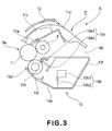
- Figure 3 is a schematic sectional view of the process cartridge B in this embodiment.
- the process cartridge B includes a drum unit 11 in which the photosensitive drum 7 and at least one process means are provided.
- the process means there are, e.g., a charging means for electrostatically charging the photosensitive drum 7, a developing means for developing the electrostatic latent image formed on the photosensitive drum 7, a cleaning means for removing the toner remaining on the photosensitive drum 7, and the like.
- the process cartridge B in this embodiment includes the photosensitive drum 7 provided with a photosensitive layer.
- a voltage is applied from a charging roller 8 which is the charging means (charging member), by which the surface of the photosensitive drum 7 is uniformly charged.
- the charged surface of the photosensitive drum 7 is exposed, through an exposure opening 9b, to information light (light image) on the basis of image information from an optical system 1 ( Figure 1 ).
- the electrostatic latent image is formed on the surface of the photosensitive drum 7.
- the electrostatic latent image is to be developed by a developing unit 10.
- the developing unit 10 feeds the toner, contained in a toner chamber 10a which is a toner accommodating portion, by a rotatable toner feeding member 10b. Then, a developer carrying member 10d containing a fixed magnet 10c is rotated. With this, a toner layer to which a triboelectric charge is provided by a developing blade 10e is formed on the developer carrying member 10d and then the toner (layer) is transferred onto the photosensitive drum 7 depending on the electrostatic latent image. By this operation, the toner image is formed into a visualized image.
- the process cartridge B in this embodiment rotatably supports the photosensitive drum 7. Further, the process cartridge B is constituted by a drum supporting frame 11d into which the cleaning blade 11a and the charging roller 8 are incorporated and by a developing device frame 10f into which the developer carrying member 10d and the toner chamber 10a are incorporated.
- Figure 4 is a perspective view for illustrating assembling and disassembling of the drum unit 11 in this embodiment.
- a drum shutter 12 show in Figure 3 is omitted.
- the drum unit 11 is constituted by the photosensitive drum 7, the drum supporting frame 11d, the charging roller 8, the cleaning blade 11a and the drum shutter 12.
- a drum gear 50 is connected at an end of the photosensitive drum 7.
- the drum gear 50 is prepared by integrally assembling a coupling 40 which is a drive transmitting means for transmitting a driving force from the image forming apparatus main assembly to the process cartridge B, a shaft portion 52 for permitting the photosensitive drum 7 to be rotatably supported by the drum supporting frame 11d, and a drive transmitting gear 41 for transmitting the driving force to the developer carrying member 10d.
- a flange 51 provided with a supporting hole 53 is connected to the photosensitive drum 7.
- a bearing 60 is connected to the drum supporting frame 11d by a fixing means such as a screw. Further, at the other side of the photosensitive drum 7, a metallic positioning pin 61 is press-fitted into a positioning portion 62 of the drum supporting frame 11d. As a result, the photosensitive drum is rotatably supported by the drum supporting frame 11d.
- a metal-made earth plate (not shown) is attached so as to contact an inner diameter portion of a drum cylinder and by contact of the earth plate to the cylinder inner diameter portion of the photosensitive drum 7 and the positioning pin 61, electrical conduction between the photosensitive drum 7 and the positioning pin 61 is ensured.
- the charging roller 8 is used for charging the surface of the photosensitive drum 7 and is rotatably provided on the drum supporting frame 11d.
- This charging roller 8 is prepared by providing successively, on a metal-mode roller shaft 8a, an electroconductive elastic layer, a high-resistance elastic layer and a protective film.
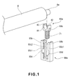
- Figure 1 is a perspective view of the supporting structure for a bearing member in this embodiment.
- Part (a) of Figure 5 is a side view of the supporting structure for the bearing member in this embodiment, and (b) and (c) of Figure 5 are sectional views of the supporting structure for the bearing member in this embodiment.
- roller shaft 8a Each of both ends of the roller shaft 8a is rotatably supported by a bearing member 80a. Further, the bearing member 80a is attached to a supporting portion 90a. The supporting portion 90a is provided on the drum supporting frame 11d.
- the supporting portion 90a has an arm pair-like shape as described later.
- the bearing member 80a is forcedly inserted into a space between arm-like portions while elastically deforming the supporting portion 90a.
- the bearing member 80a is attached to the supporting portion 90a along inner rails of the supporting portion 90a so as to be slidable in a radial direction of the photosensitive drum 7.
- the supporting portion 90a is provided with projections (preventing portions) 90b at its (upper) ends. By the projections 90b, during drum assembling, the bearing member 80a is prevented from disconnecting from the supporting portion 90a.
- a compression spring 71 is attached by using the bearing member 80a as an urging member.
- the charging roller 8 is urged toward the photosensitive drum 7 via the bearing member 80a.
- the bearing member 80a is supported by the supporting portion 90a and is constituted so as to be slidable and movable between a position (first position) in which the charging roller 8 is contacted to the photosensitive drum 7 and a position (second position) in which the charging roller 8 is separated (spaced) from the photosensitive drum 7.
- the first position is such a position that the process means (process member) such as the charging roller 8 acts on the photosensitive drum 7.
- the charging roller 8 is contacted to the photosensitive drum 7 to charge the photosensitive drum 7 but the present invention is not limited thereto.
- the position of the bearing member 80a in which the charging roller 8 and the photosensitive drum 7 form the minute gap is the first position.
- the second position is such a position that the bearing member 80a is moved away from the photosensitive drum 7.
- (a) of Figure 5 is the side view at the first position in which the charging roller 8 is contacted to the photosensitive drum 7
- (b) of Figure 5 is the sectional view at the first position
- (c) of Figure 5 is the sectional view at the second position in which the charging roller 8 is separated from the photosensitive drum 7.
- the bearing member 80a is provided with a bearing-side longitudinal direction movement preventing portion 80b having a projected shape extending in the sliding direction described above.
- the bearing longitudinal direction movement preventing portion 80b is sandwiched by a frame-side longitudinal direction movement preventing portion 90c of the supporting portion 90a, i.e., sandwiched between a frame-side inner longitudinal direction movement preventing portion 90c1 and a frame-side outer longitudinal direction movement preventing portion 90c2.
- the longitudinal direction movement of the bearing member 80a is prevented by the contact of the bearing-side longitudinal direction movement preventing portion 80b to the frame-side inner longitudinal direction movement preventing portion 90c1 and the frame-side outer longitudinal direction movement preventing portion 90c2.
- the frame-side inner longitudinal direction movement preventing portion 90c1 is provided with a cut-away portion (dismount portion) 90d having a size such that the bearing-side longitudinal direction movement preventing portion 80b can pass through the frame-side inner longitudinal direction movement preventing portion 90c1 via the cut-away portion 90d.
- the bearing-side longitudinal direction movement preventing portion 80b does not contact the frame-side inner longitudinal direction movement preventing portion 90c1 or the frame-side outer longitudinal direction movement preventing portion 90c2, so that the bearing member 80a can be dismounted from the drum supporting frame 11d.
- the cut-away portion 90d is provided to any one of the frame-side inner longitudinal direction movement preventing portion 90c1 and the frame-side outer longitudinal direction movement preventing portion 90c2.
- a direction in which the bearing member 80a is dismounted from the drum supporting frame 11d can be limited to one of two directions with respect to the longitudinal direction.
- the cut-away portion 90d is provided to the frame-side longitudinal direction movement preventing portion preventing portion 90c1 as a longitudinal inner portion, so that the bearing member 80a can be dismounted, at the second position, toward the longitudinal side (an arrow direction in (c) of Figure 5 ). Further, the movement of the bearing member 80a toward the longitudinal outside is prevented by the contact between the bearing-side longitudinal direction movement preventing portion 80b and the frame-side longitudinal direction movement preventing portion 90c2 provided at the longitudinal outside.
- the bearing member 80a includes, at the first position, the bearing-side longitudinal direction movement preventing portion 80b provided in at least one of the two directions with respect to the axial direction of the charging roller 8. At the first position, the bearing-side longitudinal direction movement preventing portion 80b overlaps with the supporting portion 90a as seen from the axial direction of the charging roller 8. On the other hand, at the second position, the bearing-side longitudinal direction movement preventing portion 80b does not overlap with the supporting portion 90a as seen from the axial direction of the charging roller 8, thus being dismountable.
- the assembling of the bearing member 80a to the supporting portion 90a is performed from the photosensitive drum 7 side.
- the assembling direction is not limited thereto but may also be the longitudinal direction.
- the bearing member 80a can be assembled to the supporting portion 90a in the longitudinal direction (a position opposite to the arrow direction in (c) of Figure 5 ) so that the bearing-side longitudinal direction movement preventing portion 80b enter the supporting portion 90a through the cut-away portion 90d provided to the frame-side inner longitudinal direction movement preventing portion 90c1.
- the cut-away portion 90d constitutes an assembling portion.
- an assembling position with respect to the longitudinal direction is the second position.
- the bearing member 80a is moved toward the frame by urging force of the compression spring 71 and is stopped at an abutting position in which the bearing member 80a abuts against the projection 90b provided at the end of the supporting portion 90a.
- the bearing member 80a includes, as shown in Figure 1 , a U-shaped engaging portion 81, so that the roller shaft 8a is constituted so as not to be disengaged from the surface member 80a.
- an entering opening 82 provided at an end of the engaging portion 81 is constituted so as to have a diameter narrower (smaller) than that of the roller shaft 8a.
- the charging roller 8 is rotated by the rotation of the photosensitive drum 7 and at this time, a voltage is applied to the charging roller 8 to uniformly charge the surface of the photosensitive drum 7.
- one of the bearing members 80a provided at longitudinal ends of the charging roller 8 is constituted by an electroconductive member of an electroconductive polyacetal resin material or the like.
- the voltage is applied to the roller shaft 8a via a contact member 60 ( Figure 4 ) and the compression spring 71, which is electroconductive, for urging the bearing member 80a.
- the bearing member 80a provided at the other end side is also constituted with a polyacetal resin material which has a good sliding property with the metal-mode roller shaft 8a and which is excellent in anti-wearing property.
- the charging roller 8 and the developer carrying member and the like are reassembled through the steps of screening, cleaning, inspection and the like and then are used but the drum supporting frame 11d and the like are crushed and then are reused as a material.
- the drum supporting frame 11d and the bearing member 80a are constituted by different materials, when those members are crushed together, a mechanical property is deteriorated during the reuse as the material.
- the drum supporting frame 11d are the bearing member 80a may desirably be originally formed of the same material.
- the bearing member 80a is formed of the polyacetal resin material as described above and the drum supporting frame 11d is formed of a polystyrene resin material, thus being constituted by different materials. For this reason, there is a need to remove and fractionate the bearing member 80a, so that a constitution by which the bearing member 80a is easily dismountable from the drum supporting frame 11d is required.
- a disassembling method of a spent process cartridge B will be specifically described with reference to Figures 4 to 6 .
- Figure 6 is a perspective view for illustrating assembling of a developing unit to the drum unit in this embodiment.
- a pin 30 engaged in a hole 11e and a connecting hole 10g 8 is pulled out in the longitudinal direction to separate the developing unit 10 and the drum unit 11.
- a screw fixed to a bearing 60 of the drum unit 11 is disconnected and then the bearing 60 and a positioning pin 61 are disconnected, so that the photosensitive drum 7 is dismounted from the drum supporting frame 11d.
- the charging roller 8 is pulled out in the photosensitive drum 7 axial direction, so that the charging roller 8 is dismounted from the bearing member 80a.
- the diameter of the roller shaft 8a of the charging roller 8 is smaller than the gap of the pair of projections 90b and therefore the charging roller 8 can be pulled out in the photosensitive drum 7 axial direction.
- the cleaning blade 11a becomes dismountable by disconnecting the screws fixed at both ends. Then, the residual toner in the removed toner accommodating portion 11c is removed.
- the bearing member 80a is pushed from the photosensitive drum 7 side. Then, the bearing member 80a is slid to the second position and thereafter is shifted in the longitudinal direction. Thus, the bearing member 80a can easily be dismounted from the drum supporting frame 11d.
- the bearing member 80a and the compression spring 71 can be dismounted simultaneously from the drum supporting frame 11d.
- a circular projected-shaped press-fitting portion 80c is provided on the bearing member 80a and an inner diameter of the compression spring 71 is set to be smaller than an outer diameter of the press-fitting portion 80c, and then the press-fitting portion 80c may be inserted and fixed in the compression spring 71.
- Parts (a), (b) and (c) of Figure 7 are a side view and sectional views of the supporting structure for the bearing member in this embodiment.
- (a) of Figure 7 is the side view of the supporting structure at the first position in which the charging roller 8 is contacted to the photosensitive drum 7
- (b) of Figure 7 is the sectional view of the supporting structure at the first position
- (c) of Figure 7 is the sectional view of the supporting structure at the second position in which the charging roller 8 is separated from the photosensitive drum 7.
- Figure 8 is a perspective view of the bearing member in this embodiment.
- the supporting portion 90a is provided with a frame-side longitudinal direction movement preventing portion 90c having an arm pair-like shape constituted to sandwich the bearing member 80a.
- the bearing member 80a is provided, as the preventing portion, with a bearing-side inner longitudinal direction movement preventing portion 80b1 and a bearing-side outer longitudinal direction movement preventing portion 80b2 which are extended in the sliding direction.
- the bearing-side inner and outer longitudinal direction movement preventing portions 80b1 and 80b2 are adjacent. For this reason, at the first position, the movement of the bearing member 80a in the longitudinal direction is prevented by the contact of the frame-side longitudinal direction movement preventing portion 90c to the bearing-side inner and outer longitudinal direction movement preventing portions 80b1 and 80b2.
- the frame-side longitudinal direction movement preventing portion 90c is provided with a cut-away portion 90d.
- the bearing-side inner and outer longitudinal direction movement preventing portions 80b1 and 80b2 does not contact the frame-side longitudinal direction movement preventing portion 90c.
- the bearing member 80a can be dismounted from the drum supporting frame 11d in the longitudinal direction (arrow direction).
- a preventing width in the sliding direction is set so that only one of the bearing-side inner and outer longitudinal direction movement preventing portions 80b1 and 80b2 is longer than the other.
- the direction in which the bearing member 80a is dismounted from the drum supporting frame 11d can be limited to one direction.
- the width, with respect to the sliding direction, of the bearing-side inner longitudinal direction movement preventing portion 80b1 at the longitudinal inside is set at a larger value.
- the bearing member 80a can be dismounted only toward the longitudinal inside (the arrow direction in (c) of Figure 7 ).
- the movement of the bearing member 80a toward the longitudinal outside is prevented by the contact between the frame-side longitudinal direction movement preventing portion 90c and the bearing-side inner longitudinal direction movement preventing portion 80b1.
- the bearing member 80a may also be provided with an abutting portion (contact portion) 83 for preventing the movement of the charging roller 8 in the longitudinal direction.
- rigidity of the supporting portion 90a can be set at a low level. For this reason, the insertion of the bearing member 80a while elastically deforming the supporting portion 90a becomes easy.
- Figure 9 is a schematic view for illustrating the supporting structure for the bearing member in this embodiment.
- Parts (a), (b) and (c) of Figure 10 are a side view and sectional views of the supporting structure for the bearing member in this embodiment.
- FIG. 10 is the side view of the supporting structure at the first position in which the charging roller 8 is contacted to the photosensitive drum 7
- (b) of Figure 10 is the sectional view of the supporting structure at the first position
- (c) of Figure 10 is the sectional view of the supporting structure at the second position in which the charging roller 8 is separated from the photosensitive drum 7.
- Figure 11 is a perspective view of the supporting structure for the bearing member in this embodiment.
- the supporting portion 90a is provided with a guiding portion 91 which is inclined at an angle with respect to the sliding portion.
- the bearing member 80a When the bearing member 80a is moved from the first position to the second position, the bearing member 80a is guided in the longitudinal inside direction while being contacted to the guiding portion 91.
- the longitudinal inside direction is the axial direction of the charging roller 8 and a direction toward a central portion of the charging roller 8.
- the preventing widths, with respect to the sliding direction, of the bearing-side inner and outer longitudinal direction movement preventing portions 80b1 and 80b2 are set so that only the bearing-side inner longitudinal direction movement preventing portion 80b1 is long as shown in (b) of Figure 10 .
- the direction in which the bearing member 80a is dismounted from the drum supporting frame 11d can be limited to the longitudinal inside direction.
- Figure 12 is a schematic view for illustrating the supporting structure for the bearing member in the modified example of this embodiment.
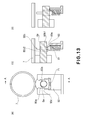
- Parts (a), (b) and (c) of Figure 13 are a side view and sectional views of the supporting structure for the bearing member in the modified example of this embodiment.
- (a) of Figure 13 is the side view of the supporting structure at the first position in which the charging roller 8 is contacted to the photosensitive drum 7
- (b) of Figure 13 is the sectional view of the supporting structure at the first position
- (c) of Figure 13 is the sectional view of the supporting structure at a position in which the bearing member 80a contacts the guiding portion 91.
- Figure 14 is a schematic sectional view of the process cartridge in this embodiment.
- the transfer 4 is integrally disposed in the process cartridge B. Both shaft ends of the transfer roller 4 are rotatably supported by bearing members (not shown). The bearing members are attached to supporting portions (not shown) provided on the drum supporting frame 11d. Further, the transfer roller 4 is attached so as to be slidable with respect to a radial direction of the photosensitive drum 7 by using the supporting portions as rails and is urged toward the photosensitive drum 7 by compression springs (not shown) as urging means.
- the process means is the transfer means (transfer member) and the supporting structure of the transfer roller 4 for the drum supporting frame 11d has the same constitution as that in the case of the charging roller 8 described above.
- dismounting of the bearing member from the drum supporting frame 11d becomes easy and thus disassembling easiness is improved.
- the bearing member 80a is supported by the supporting portion 90a and is constituted so as to be slidable and movable between the position (first position) in which the charging roller 8 is contacted to the photosensitive drum 7 and the position (second position) in which the charging roller 8 is separated from the photosensitive drum 7.
- An end portion 90e of the supporting portion 90a is a suppressing portion for suppressing disconnection, from the supporting portion 90a, of the bearing member 80a urged by the compression spring 71.
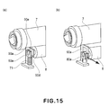
- (a) of Figure 15 is a perspective view of the process cartridge at the first position in which the charging roller 8 is contacted to the photosensitive drum 7, and
- (b) of Figure 15 is a perspective view of the process cartridge at the second position in which the charging roller 8 is separated from the photosensitive drum 7.
- the bearing member 80a cannot be dismounted at the first position but can be dismounted at the second position in an arrow direction (cross-sectional direction perpendicular to the axis of the photosensitive drum 7) in (b) of Figure 15 . Further, the dismounting direction is different from a presence direction of the photosensitive drum 7 and therefore the dismounting of the bearing member 80a becomes possible even in the state in which the photosensitive drum 7 is mounted, so that disassembling easiness is improved.
- the present invention is not limited thereto.
- a cleaning roller for collecting the transfer residual toner on the photosensitive drum 7 in contact with the photosensitive drum 7 may also be used.
- a cartridge detachably mountable to a main assembly of an image forming apparatus includes a process member including a shaft acting on an image bearing member; a bearing member for supporting the process means; and a frame including a supporting portion for movably supporting the bearing member.
- the bearing member is movable, by moving the supporting portion, between a first position in which the process member acts on the image bearing member and a second position which is remote from the image bearing member more than the first position.
- the cartridge further includes an urging member for urging the bearing member from the second position toward the first position; a suppressing portion for suppressing dismounting of the bearing member, urged by the urging member, from the supporting portion; and a dismounting portion for permitting dismounting of the bearing member from the frame at the second position.
Landscapes
- Engineering & Computer Science (AREA)
- Computer Vision & Pattern Recognition (AREA)
- Physics & Mathematics (AREA)
- General Physics & Mathematics (AREA)
- Life Sciences & Earth Sciences (AREA)
- Manufacturing & Machinery (AREA)
- Sustainable Development (AREA)
- Electrophotography Configuration And Component (AREA)
- Discharging, Photosensitive Material Shape In Electrophotography (AREA)
- Electrostatic Charge, Transfer And Separation In Electrography (AREA)
Applications Claiming Priority (2)
| Application Number | Priority Date | Filing Date | Title |
|---|---|---|---|
| JP2010210497 | 2010-09-21 | ||
| JP2011190350A JP2012088689A (ja) | 2010-09-21 | 2011-09-01 | カートリッジ及び画像形成装置 |
Publications (1)
| Publication Number | Publication Date |
|---|---|
| EP2431822A2 true EP2431822A2 (de) | 2012-03-21 |
Family
ID=45047554
Family Applications (1)
| Application Number | Title | Priority Date | Filing Date |
|---|---|---|---|
| EP11181932A Withdrawn EP2431822A2 (de) | 2010-09-21 | 2011-09-20 | Kartusche und Bilderzeugungsvorrichtung |
Country Status (4)
| Country | Link |
|---|---|
| US (1) | US20120070187A1 (de) |
| EP (1) | EP2431822A2 (de) |
| JP (1) | JP2012088689A (de) |
| CN (1) | CN102411295A (de) |
Families Citing this family (12)
| Publication number | Priority date | Publication date | Assignee | Title |
|---|---|---|---|---|
| US8874003B2 (en) * | 2012-05-17 | 2014-10-28 | Fuji Xerox Co., Ltd. | Supporting mechanism and image forming apparatus |
| JP5953930B2 (ja) * | 2012-05-18 | 2016-07-20 | 富士ゼロックス株式会社 | 支持機構及び画像形成装置 |
| US9176456B2 (en) * | 2013-08-09 | 2015-11-03 | Kyocera Document Solutions Inc. | Image forming unit and image forming apparatus comprising first process roller and second process roller |
| JP5860853B2 (ja) * | 2013-08-09 | 2016-02-16 | 京セラドキュメントソリューションズ株式会社 | 画像形成ユニット及び画像形成装置 |
| JP6415198B2 (ja) | 2013-09-12 | 2018-10-31 | キヤノン株式会社 | カートリッジ |
| JP6208001B2 (ja) * | 2013-12-24 | 2017-10-04 | シャープ株式会社 | プロセスユニットおよびそれを備える画像形成装置、ならびに帯電器の離間方法 |
| JP5822967B2 (ja) * | 2014-03-10 | 2015-11-25 | キヤノン株式会社 | ベルト搬送装置及び画像形成装置 |
| US9285758B1 (en) | 2014-12-19 | 2016-03-15 | Lexmark International, Inc. | Positional control features between replaceable units of an electrophotographic image forming device |
| US9291992B1 (en) | 2014-12-19 | 2016-03-22 | Lexmark International, Inc. | Positional control features for an imaging unit in an electrophotographic image forming device |
| US9411303B1 (en) * | 2015-04-10 | 2016-08-09 | Lexmark International, Inc. | Positioning stop assembly for a replaceable unit of an electrophotographic image forming device |
| JP6590563B2 (ja) * | 2015-07-09 | 2019-10-16 | キヤノン株式会社 | 加熱ベルトユニット |
| JP6409798B2 (ja) | 2016-03-01 | 2018-10-24 | 京セラドキュメントソリューションズ株式会社 | 帯電装置及びそれを備えた像担持体ユニット並びに画像形成装置 |
Citations (2)
| Publication number | Priority date | Publication date | Assignee | Title |
|---|---|---|---|---|
| JPH06301249A (ja) | 1992-09-04 | 1994-10-28 | Canon Inc | プロセスカートリッジの組み立て方法及び帯電ローラの組み付け方法及び画像形成装置及びプロセスカートリッジ及びプロセス手段の組み付け方法 |
| JP3363889B2 (ja) | 2001-03-09 | 2003-01-08 | キヤノン株式会社 | プロセスカートリッジの再生産方法 |
Family Cites Families (9)
| Publication number | Priority date | Publication date | Assignee | Title |
|---|---|---|---|---|
| GB2214575B (en) * | 1988-01-20 | 1992-05-20 | Xerox Corp | Magnetic brush development apparatus. |
| JP3200141B2 (ja) * | 1991-04-08 | 2001-08-20 | キヤノン株式会社 | 画像形成装置及び画像形成装置に着脱自在なプロセスカートリッジ |
| JP2001201915A (ja) * | 2000-01-18 | 2001-07-27 | Canon Inc | プロセスカートリッジ及び画像形成装置 |
| JP2002214885A (ja) * | 2001-01-15 | 2002-07-31 | Canon Inc | プロセスカートリッジ |
| CN2906694Y (zh) * | 2006-05-09 | 2007-05-30 | 周茂柏 | 充电辊的支撑装置 |
| JP5036240B2 (ja) * | 2006-07-21 | 2012-09-26 | 株式会社リコー | 帯電ローラ軸受部材、プロセスカートリッジ及び画像形成装置 |
| JP4538026B2 (ja) * | 2007-08-20 | 2010-09-08 | 株式会社沖データ | 帯電装置、画像形成ユニット及び画像形成装置 |
| JP2011048133A (ja) * | 2009-08-27 | 2011-03-10 | Ricoh Co Ltd | プロセスカートリッジおよび画像形成装置 |
| JP2011186378A (ja) * | 2010-03-11 | 2011-09-22 | Canon Inc | プロセスカートリッジおよび画像形成装置 |
-
2011
- 2011-09-01 JP JP2011190350A patent/JP2012088689A/ja not_active Withdrawn
- 2011-09-14 US US13/232,205 patent/US20120070187A1/en not_active Abandoned
- 2011-09-20 EP EP11181932A patent/EP2431822A2/de not_active Withdrawn
- 2011-09-21 CN CN2011102806663A patent/CN102411295A/zh active Pending
Patent Citations (2)
| Publication number | Priority date | Publication date | Assignee | Title |
|---|---|---|---|---|
| JPH06301249A (ja) | 1992-09-04 | 1994-10-28 | Canon Inc | プロセスカートリッジの組み立て方法及び帯電ローラの組み付け方法及び画像形成装置及びプロセスカートリッジ及びプロセス手段の組み付け方法 |
| JP3363889B2 (ja) | 2001-03-09 | 2003-01-08 | キヤノン株式会社 | プロセスカートリッジの再生産方法 |
Also Published As
| Publication number | Publication date |
|---|---|
| US20120070187A1 (en) | 2012-03-22 |
| JP2012088689A (ja) | 2012-05-10 |
| CN102411295A (zh) | 2012-04-11 |
Similar Documents
| Publication | Publication Date | Title |
|---|---|---|
| EP2431822A2 (de) | Kartusche und Bilderzeugungsvorrichtung | |
| CN101715570B (zh) | 处理盒以及电子照相成像设备 | |
| US10197967B2 (en) | Cartridge and electrophotographic image forming apparatus | |
| EP0570249B1 (de) | Verfahren zum Einbau einer Klinge in den Rahmen einer Arbeitseinheit | |
| EP0753800A2 (de) | Kopierkassette, Verfahren zum Zusammenbau dieser Kassette und elektrophotographisches Bilderzeugungsgerät | |
| AU2024204679A1 (en) | Drum unit, cartridge, electrophotographic image forming apparatus and coupling member | |
| US20150010320A1 (en) | Cartridge, image forming apparatus and main assembly of image forming apparatus | |
| EP1843216B1 (de) | Montageverfahren für lichtempfindliche Trommel für eine Druckerkassette | |
| CN106547187B (zh) | 盒和支承部件 | |
| KR20020001649A (ko) | 프로세스 카트리지를 위한 재생 방법 | |
| CN111077752B (zh) | 显影盒及采用此的电子照相方式的图像形成装置 | |
| JP2009210630A (ja) | タンデム型感光体ユニットおよび画像形成装置 | |
| JPH10240102A (ja) | プロセスカートリッジ | |
| KR102921072B1 (ko) | 카트리지 및 카트리지를 분해하는 방법 | |
| JP3110581B2 (ja) | ブレード部材及びブレード部材の取り付け方法及びプロセスカートリッジ及びクリーニング装置 | |
| JP2002082579A (ja) | プロセスカートリッジ | |
| JP5683221B2 (ja) | プロセス手段の支持固定構造及びこれを有する画像形成装置、プロセスカートリッジ、現像装置 | |
| KR20180002514A (ko) | 화상 형성 장치 및 카트리지 | |
| JP3241826B2 (ja) | プロセスカートリッジ及び画像形成装置 | |
| JP2003208077A (ja) | プロセスカートリッジ及び該プロセスカートリッジを備えた画像形成装置 | |
| US12554215B2 (en) | Image forming apparatus | |
| US20260126742A1 (en) | Image forming apparatus | |
| JP2015191070A (ja) | プロセスカートリッジ及びこれを用いた画像形成装置 | |
| JP2020134560A (ja) | 画像形成装置、及び、プロセスカートリッジ | |
| JP2008039902A (ja) | 現像装置、プロセスカートリッジ及び電子写真画像形成装置 |
Legal Events
| Date | Code | Title | Description |
|---|---|---|---|
| PUAI | Public reference made under article 153(3) epc to a published international application that has entered the european phase |
Free format text: ORIGINAL CODE: 0009012 |
|
| AK | Designated contracting states |
Kind code of ref document: A2 Designated state(s): AL AT BE BG CH CY CZ DE DK EE ES FI FR GB GR HR HU IE IS IT LI LT LU LV MC MK MT NL NO PL PT RO RS SE SI SK SM TR |
|
| AX | Request for extension of the european patent |
Extension state: BA ME |
|
| STAA | Information on the status of an ep patent application or granted ep patent |
Free format text: STATUS: THE APPLICATION HAS BEEN WITHDRAWN |
|
| 18W | Application withdrawn |
Effective date: 20140102 |