EP2431129A1 - Werkzeugteil oder Werkzeughalter für eine Werkzeugmaschine - Google Patents
Werkzeugteil oder Werkzeughalter für eine Werkzeugmaschine Download PDFInfo
- Publication number
- EP2431129A1 EP2431129A1 EP11193304A EP11193304A EP2431129A1 EP 2431129 A1 EP2431129 A1 EP 2431129A1 EP 11193304 A EP11193304 A EP 11193304A EP 11193304 A EP11193304 A EP 11193304A EP 2431129 A1 EP2431129 A1 EP 2431129A1
- Authority
- EP
- European Patent Office
- Prior art keywords
- tool
- input shaft
- output shaft
- front portion
- rear portion
- Prior art date
- Legal status (The legal status is an assumption and is not a legal conclusion. Google has not performed a legal analysis and makes no representation as to the accuracy of the status listed.)
- Granted
Links
- 230000008878 coupling Effects 0.000 claims description 6
- 238000010168 coupling process Methods 0.000 claims description 6
- 238000005859 coupling reaction Methods 0.000 claims description 6
- 230000005540 biological transmission Effects 0.000 description 8
- 125000006850 spacer group Chemical group 0.000 description 7
- 230000001351 cycling effect Effects 0.000 description 1
- 230000007246 mechanism Effects 0.000 description 1
- 238000012986 modification Methods 0.000 description 1
- 230000004048 modification Effects 0.000 description 1
Images


Classifications
-
- B—PERFORMING OPERATIONS; TRANSPORTING
- B25—HAND TOOLS; PORTABLE POWER-DRIVEN TOOLS; MANIPULATORS
- B25B—TOOLS OR BENCH DEVICES NOT OTHERWISE PROVIDED FOR, FOR FASTENING, CONNECTING, DISENGAGING OR HOLDING
- B25B23/00—Details of, or accessories for, spanners, wrenches, screwdrivers
- B25B23/14—Arrangement of torque limiters or torque indicators in wrenches or screwdrivers
-
- B—PERFORMING OPERATIONS; TRANSPORTING
- B25—HAND TOOLS; PORTABLE POWER-DRIVEN TOOLS; MANIPULATORS
- B25B—TOOLS OR BENCH DEVICES NOT OTHERWISE PROVIDED FOR, FOR FASTENING, CONNECTING, DISENGAGING OR HOLDING
- B25B15/00—Screwdrivers
- B25B15/001—Screwdrivers characterised by material or shape of the tool bit
-
- B—PERFORMING OPERATIONS; TRANSPORTING
- B25—HAND TOOLS; PORTABLE POWER-DRIVEN TOOLS; MANIPULATORS
- B25B—TOOLS OR BENCH DEVICES NOT OTHERWISE PROVIDED FOR, FOR FASTENING, CONNECTING, DISENGAGING OR HOLDING
- B25B23/00—Details of, or accessories for, spanners, wrenches, screwdrivers
- B25B23/02—Arrangements for handling screws or nuts
- B25B23/08—Arrangements for handling screws or nuts for holding or positioning screw or nut prior to or during its rotation
- B25B23/12—Arrangements for handling screws or nuts for holding or positioning screw or nut prior to or during its rotation using magnetic means
-
- B—PERFORMING OPERATIONS; TRANSPORTING
- B25—HAND TOOLS; PORTABLE POWER-DRIVEN TOOLS; MANIPULATORS
- B25B—TOOLS OR BENCH DEVICES NOT OTHERWISE PROVIDED FOR, FOR FASTENING, CONNECTING, DISENGAGING OR HOLDING
- B25B23/00—Details of, or accessories for, spanners, wrenches, screwdrivers
- B25B23/14—Arrangement of torque limiters or torque indicators in wrenches or screwdrivers
- B25B23/141—Mechanical overload release couplings
Definitions
- This application relates to a tool bit or a tool holder for use with a power tool, such as an impact driver, a screwgun, a drill, a hammer drill, or a screwdriver.
- a power tool such as an impact driver, a screwgun, a drill, a hammer drill, or a screwdriver.
- a large driving torque e.g., approximately 500 inch-lbs
- that torque may be generated in rapid cycles (e.g., approximately every 2 milliseconds). Due to the large driving torque and the rapid cycling, current tool bits (e.g., screwdriving bits) and/or tool holders often fail when used with these types of power tools, especially with impact drivers.
- This application relates to a tool, such as a tool bit (e.g., a screwdriving bit or drill bit) or tool holder (e.g., for a screwdriving bit, a drill bit, or a screw or nut), for use with a power tool (e.g., an impact driver, a screwgun, a drill, a hammer drill, or a screwdriver).
- the tool bit or tool holder includes a clutch that that releases the force transmitted from the power tool to the tool when the torque exceeds a predetermined amount.
- the clutch makes use of a radial band-spring to prevent a series of rollers from slipping over an incline.
- a tool for use with a power tool includes an input shaft, an output shaft, and a clutch assembly.
- the input shaft has a rear portion with a shank configured to be removably coupled to a power tool, and a front portion.
- the output shaft has a front portion configured to be coupled to a tool bit, and a rear portion, the rear portion of the output shaft rotatably coupled to the front portion of the input shaft.
- the clutch assembly releasably couples the input shaft to the output shaft, and includes: (i) at least one recess defined in one of the front portion of the input shaft and the rear portion of the output shaft; (ii) at least one aperture defined in the other of the front portion of the input shaft and the portion of the output shaft; (iii) at least one roller received in the at least one aperture; and (iv) a spring that biases the at least one roller radially inwardly into the at least one recess such that torque is transmitted from the input shaft to the output shaft when a predetermined torque threshold is not exceeded, and that enables release of the at least one roller radially outwardly from the at least one recess such that torque is not transmitted from the input shaft to the output shaft when the predetermined torque threshold is exceeded.
- the shank may have at least a portion having a hex shaped cross-section.
- the shank may also include a portion having a round cross-section disposed between the portion having the hex-shaped cross-section and the front portion of the input shaft to enable attachment of the shank to a screwgun.
- the front portion of the output shaft may define a socket configured to removably receive and a retain a tool bit.
- a tool bit may be integral with the front portion of the output shaft.
- the at least one recess may include a plurality of longitudinal grooves.
- the at least one aperture may include a plurality of longitudinal slots.
- the at least one roller may include a plurality of pins, each pin received in one of the plurality of longitudinal slots.
- the spring may include at least one spring band received around the longitudinal slots and pins to bias the pins into the longitudinal grooves when the predetermined torque threshold is not exceeded, and that expands to release the pins from the longitudinal grooves when the predetermined torque threshold is exceeded.
- the at least one spring band may include an inner spring band and an outer spring band at least partially overlapping the inner spring band.
- a clutch lock-out member may be moveable between a first position and a second position, wherein in the second position the clutch lock-out member prevents interruption of torque transmission from the input shaft to the output shaft
- a tool for use with a power tool includes an input shaft, an output shaft, a spring-biased clutch, and a clutch lock-out assembly.
- the input shaft has a rear portion with a shank configured to be removably coupled to an output of a power tool.
- the output shaft has a front portion configured to be coupled to a tool bit.
- the spring-biased clutch couples a front portion of the input shaft to a rear portion of the output shaft so that torque is transmitted from the input shaft to the output shaft when a predetermined torque threshold is not exceeded, and torque transmission from the input shaft to the output shaft is interrupted when the predetermined torque threshold is exceeded.
- the clutch lock-out assembly is moveable between a first position and a second position, wherein in the second position the clutch lock-out member prevents interruption of torque transmission from the input shaft to the output shaft.
- the spring biased clutch may include: (i) a generally cylindrical shaft formed on one of a front portion of the input shaft and a rear portion of the output shaft, the cylindrical shaft defining at least one recess; (ii) a generally cylindrical sleeve formed on the other of the front portion of the input shaft and the rear portion of the output shaft, the sleeve received over the cylindrical shaft, and defining at least one aperture; (iii) at least one roller received in the at least one aperture; and (iv) at least one spring band received over the generally cylindrical sleeve, wherein the spring band biases the at least one roller into the at least one recess such that torque is transmitted from the input shaft to the output shaft when a predetermined torque threshold is not exceeded, and that expands to enable release of the at least one roller from the at least one recess such that torque is not transmitted from the input shaft to the output shaft when the predetermined torque threshold is exceeded.
- the clutch lock-out assembly may include a longitudinally moveable bushing received over the spring band, the busing having an internal shoulder, such that when the bushing is in the first position, the bushing enables expansion of the spring band, and when the bushing is in the second position, the shoulder abuts the spring band to prevent expansion of the spring band.
- the at least one recess may include a plurality of longitudinal grooves
- the at least one aperture may include a plurality of longitudinal slots
- the at least one roller may include a plurality of pins, each pin received in one of the plurality of longitudinal slots.
- the at least one spring band may include an inner spring band and an outer spring band at least partially overlapping the inner spring band.
- the shank may include a fitting having a hex shaped cross-section.
- the front portion of the output shaft may define a socket configured to removably receive and a retain a tool bit. A tool bit may be integral with the front portion of the output shaft.
- a tool for use with a power tool includes an input shaft having a rear portion with a shank of hex-shaped cross-section configured to be removably coupled to an output of a power tool, an output shaft having a front portion defining a socket and a retaining member configured to receive a tool bit; and a clutch assembly coupling the input shaft to the output shaft.
- the clutch assembly includes: (i) a generally cylindrical shaft formed on one of a front portion of the input shaft and a rear portion of the output shaft, the cylindrical shaft defining a plurality of longitudinal grooves; (ii) a generally cylindrical sleeve formed on the other of the front portion of the input shaft and the rear portion of the output shaft, the sleeve received over the cylindrical shaft, and defining a plurality of longitudinal slots; (iii) a plurality of roller pins, each roller pin received in one of the plurality of longitudinal slots; and (iv) at least one spring band received over the generally cylindrical sleeve, the spring band biasing the roller pins into the longitudinal grooves such that torque is transmitted from the input shaft to the output shaft when a predetermined torque threshold is not exceeded, and spring band expanding to enable release of the roller pins from the longitudinal grooves such that torque is not transmitted from the input shaft to the output shaft when the predetermined torque threshold is exceeded.
- a clutch lock-out assembly that includes a bushing with an internal shoulder is received over the spring band and moveable between a first position and a second position, wherein when the bushing is in the first position, the bushing enables expansion of the spring band and interruption of torque transmission from the input shaft to the output shaft when the predetermined torque threshold is exceeded, and when the bushing is in the second position, the shoulder abuts the spring band to prevent expansion of the spring band and prevent interruption of torque transmission from the input shaft to the output shaft even when the predetermined torque threshold is exceeded.
- a tool 10 for use with a power tool has a generally cylindrical input shaft 12, a generally cylindrical output shaft 20, and a clutch assembly 30 releasably coupling the input shaft 12 to the output shaft 20.
- the input shaft 12 has a rear portion 14, a middle portion 13, and a front portion 18.
- the rear portion 14 comprises a shank 16 with a hex-shaped cross-section and an annular groove 17, for coupling the rear portion 14 to a tool holder, such as a chuck, of the power tool.
- the shank could have a different cross-sectional shape, such as round or square.
- the middle portion 13 is has a round cross-section and receives a large sleeve bearing 15.
- the front portion 18 has a round gross-section and plurality of recesses in the form of longitudinal grooves 38, the purpose of which will be described below.
- the front portion 18 also has a smaller diameter nose 19 of round cross-section, over which a small sleeve bearing 21 is received.
- the output shaft 20 has a rear portion 23 and a front portion 33.
- the rear portion 23 defines a longitudinal bore 22 in which the front portion 18 of the input shaft 12, the small bearing 21, the middle portion 13 of the input shaft, and the large bearing 15 are rotatably received.
- the large sleeve bearing 15 and the small sleeve bearing 21 function as bearings between the input shaft 12 and the output shaft 20 to enable the shafts to rotate relative to one another.
- Received over the middle portion 13 of the input shaft 12 is an end cap 25 that axially retains the input shaft 12 relative to the output shaft 20.
- the rear portion 23 of the output shaft 20 also defines a plurality apertures in the form of longitudinal slots 34 that receive a plurality of rollers in the form of pins 36, the purpose of which will be described below.
- the front portion 33 has a socket 26 for receiving a tool bit, such as a screwdriving bit or a drill bit.
- the socket 26 has a hex shape for receiving a bit having a hex shaped shank.
- the socket 26 can have alternative shapes and/or configurations, such as a round shape.
- a magnet 28 Inside the socket 26 is a magnet 28 that helps retain the tool bit inside the socket 26.
- additional or other bit retaining features may be included such as a retaining ring or a biased ball.
- the bit may be made integral with the output shaft (not shown).
- the clutch assembly 30 releasably couples the input shaft 12 to the output shaft 20.
- the clutch assembly 30 includes the longitudinal grooves 38 in the input shaft 18, the longitudinal slots 34 and the pins 36 in the output shaft 36 and a spring band 42 that substantially surrounds the rear portion 23 of the output shaft 20, the pins 36, and the front portion 18 of the input shaft 12.
- the large bearing 15 and the cap 25 are received over the input shaft 12 to keep the input shaft 12, output shaft 20, and spring band 30 attached together in an axial direction.
- the spring 42 biases the rollers 36 into the grooves 38 of the input shaft 12 so that rotation of the input shaft 12 by the power tool is transmitted to the output shaft 20, and thus to the bit being held in the socket 26.
- the torque input to the input shaft 12 exceeds a predetermined amount (e.g., when the toque output from the power tool exceeds the torque rating on the clutch assembly)
- the spring 42 expands, and the rollers 36 escape from the grooves 38 on the input shaft 12 so that no torque is transmitted from the input shaft 12 to the output shaft 20. In this way, the clutch assembly 30 protects the tool 10 and the bit from instances of excessively high torque.
- the spring is a split band spring with overlapping halves. This design enables the spring to be tuned to the amount of force required to have the clutch release upon a predetermined amount of torque being applied to the shank.
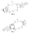
- a tool 10 for use with a power tool has a generally cylindrical input shaft 112, a generally cylindrical output shaft 120, and a clutch assembly 130 releasably coupling the input shaft 112 to the output shaft 120.
- the input shaft 112 has a rear portion 114, a middle portion 113, and a front portion 118.
- the rear portion 114 comprises a shank 116 with a hex-shaped cross-section and an annular groove 117, for coupling the rear portion 114 to a tool holder, such as a chuck, of the power tool.
- the shank could have a different cross-sectional shape, such as round or square.
- the middle portion 113 is has a round cross-section and receives a large sleeve bearing 115 and a large hog ring 127.that axially retains the sleeve bearing 115 on the middle portion 113 of the input shaft 112.
- a spacer sleeve 125 is received on the middle portion 113 of the input shaft 112 behind the large hog ring 127, and a small hog ring 129 axially retains the spacer sleeve 125 on the middle portion 113.
- the front portion 118 of the input shaft 112 has a round cross-section and plurality of recesses in the form of longitudinal grooves 138, the purpose of which will be described below.
- the front portion 118 also has a smaller diameter nose 119 of round cross-section, over which a washer 131 and a small sleeve bearing 121 are received.
- the output shaft 120 has a rear portion 123 and a front portion 133.
- the rear portion 123 defines a longitudinal bore 122 in which the front portion 118 of the input shaft 112, the small bearing 121, the a part of the middle portion 113 of the input shaft 112, and the large bearing 115 are rotatably received.
- the large sleeve bearing 115 and the small sleeve bearing 121 together function as bearings between the input shaft 112 and the output shaft 120 so that the shafts can rotate relative to one another.
- the rear portion 123 also defines a plurality apertures in the form of longitudinal slots 134 that receive a plurality of rollers in the form of pins 136, the purpose of which will be described below.
- a spacer ring 160 is held onto rear portion 123 by a C-clip 162.
- the front portion 133 of the output shaft 120 has a socket 126 for receiving a tool bit, such as a screwdriving bit or a drill bit.
- the socket 126 has a hex shape for receiving a bit having a hex shaped shank.
- the socket 126 can have alternative shapes and/or configurations, such as a round shape.
- Inside the socket 126 is a magnet 128 and a retaining ring 135 that help retain the tool bit inside the socket 126.
- additional or other bit retaining features may be included such as a biased ball.
- the bit may be made integral with the output shaft (not shown).
- the clutch assembly 130 releasably couples the input shaft 112 to the output shaft 120.
- the clutch assembly 130 includes the longitudinal grooves 138 in the input shaft 118, the longitudinal slots 134 and the pins 136 in the output shaft 136 and a pair of nested spring bands in the form of an inner spring band 142 and an outer spring band 143 that substantially surround the rear portion 123 of the output shaft 120, the pins 136, and the front portion 118 of the input shaft 112.
- the spring bands 142 and 143 bias the rollers 136 into the grooves 138 of the input shaft 112 so that rotation of the input shaft 112 by the power tool is transmitted to the output shaft 120, and thus to the bit being held in the socket 126.
- the torque input to the input shaft 112 exceeds a predetermined amount (e.g., when the torque output from the power tool exceeds the torque rating on the clutch assembly)
- the spring 142 expands, and the rollers 36 escape from the grooves 38 on the input shaft 12 so that no torque is transmitted from the input shaft 12 to the output shaft 20. In this way, the clutch assembly 30 protects the tool 10 and the bit from instances of excessively high torque.
- the tool 100 further includes a clutch lock-out assembly 150 for selectively locking out operation of the clutch 130.
- the clutch lock-out assembly 130 includes a bushing 152 with a front portion 153 and a rear portion 155.
- the bushing 152 is received over the outer spring band 143 and axially moveable between a forward or locked-out position ( FIG. 14 ) and a rearward or unlocked-out position ( FIG. 15 ).
- the front portion 153 of the busing 152 includes an internal annular groove 154 in which is received an O-ring 156, which supports the front portion 153 of the bushing 152 on the output shaft 120. When the bushing is in the forward position ( FIG.
- the O-ring 156 surrounds a portion of the front portion 133 of the output shaft 120, and when bushing is in the rearward position ( FIG. 15 ), the O-ring 156 is seated in an annular groove 158 in the front portion 133 of the output shaft 120 to help retain the bushing 152 in the latter position.
- the rear portion 155 of the bushing 152 is supported on the spacer ring 160 and includes a retaining ring 158 that abuts the spacer ring 160 when in the forward position to prevent the bushing 152 from being removed in a forward axial direction.
- the internal surface of the bushing 152 defines a shoulder 164.
- the shoulder 164 abuts against the outer spring band 143, preventing expansion of the inner spring band 142 and the outer spring band 143, which prevents disengagement of the pins 136 from the longitudinal grooves 138 of the input shaft 112.
- the input shaft 112 and output shaft 120 rotate together regardless of the amount of torque applied to the input shaft 112.
- the shoulder 164 is clear of the spring bands 142, 143, and they are allowed to expand and release the pins 136 from the longitudinal grooves 138 in the input shaft 112 when the predetermined torque threshold is exceeded.
- the clutch 130 is permitted to act to prevent torque transmission from the input shaft 112 to the output shaft 120 when the predetermined torque threshold is exceeded.
- the hex-shaped shank 116 of the input shaft 112 is received inside and coupled to a hex-shaped cavity of a tool holder 502 of an impact driver 500.
- a bit, e.g., a screwdriving bit 504 is received in and coupled to the recess 126 of the output shaft 120 to drive a fastener, e.g., a screw 506 into a workpiece W.
- the clutch 150 is engaged and the impact driver 502 is actuated by the user to drive the screw 506 into the workpiece.
- the clutch assembly 130 protects the screwdriving bit 504 from excessively high torque.
- the entire rear portion 114 of the input shaft 112, and at least a portion of the spacer sleeve 125 is received inside and coupled to a cavity of a nosepiece 602 of a drywall screwgun 600.
- the spacer sleeve 125 provides clearance for the nosepiece 602 to move axially relative to the input shaft 112 without releasing the input shaft 112 to actuate the clutch (not shown) that is inside the nosepiece 602.
- the structure and operation of the clutch inside of the nosepiece 602 is well understood to those of ordinary skill in the art.
- a bit, e.g., a screwdriving bit 604 is received in and coupled to the recess 126 of the output shaft 120 to drive a fastener, e.g., a screw 606 into a workpiece W.
- the clutch 150 is engaged and the screwgun 600 is actuated by the user to drive the screw 606 into the workpiece. If the torque input to the input shaft 112 exceeds a predetermined amount (e.g., when the torque output from the power tool exceeds the torque rating on the clutch assembly), the spring 142 expands, and the rollers 136 escape from the grooves 138 on the input shaft 112 so that no torque transmission from the input shaft 112 to the output shaft 120 is interrupted. In this way, the clutch assembly 130 protects the screwdriving bit 604 from excessively high torque.
- a tool 210 for use with a power tool has a generally cylindrical input shaft 212, a generally cylindrical output shaft 220, and a clutch assembly 230 that are substantially the same as the input shaft 112, the output shaft 112 and the clutch assembly 130 of the second embodiment of the tool 110.
- the third embodiment of the tool 230 differs from the second embodiment of the tool 110 only in that the output shaft 220 is integrally coupled to a tool bit 222 (e.g., a screwdriving bit or a drill bit) so that the tool 210 functions as a tool bit, as opposed to a tool bit holder.
- a tool bit 222 e.g., a screwdriving bit or a drill bit
- a tool 310 for use with a power tool has a generally cylindrical input shaft 312, a generally cylindrical output shaft 320, and a clutch assembly 330 that are substantially the same as the input shaft 112, the output shaft 112 and the clutch assembly 130 of the second embodiment of the tool 110.
- the fourth embodiment of the tool 330 differs from the second embodiment of the tool 110 only in that the output shaft 320 includes a front portion 333 having a hex-shaped recess 326 that is configured to receive a head of a screw or a nut, so that the tool 320 functions as a nutdriver.
- a different design for the clutch can be used, such as by using round recesses and openings in the input and output shafts, and balls instead of pins.
- other types of springs may be used in the clutch.
- the tension on the springs may be user adjustable to adjust the threshold torque setting of the clutch.
- the tool holder can include other mechanisms for holding a bit instead of a magnet, such as spring clips and/or spring loaded balls.
Landscapes
- Engineering & Computer Science (AREA)
- Mechanical Engineering (AREA)
- Details Of Spanners, Wrenches, And Screw Drivers And Accessories (AREA)
Applications Claiming Priority (3)
| Application Number | Priority Date | Filing Date | Title |
|---|---|---|---|
| US27404209P | 2009-08-12 | 2009-08-12 | |
| US12/846,912 US8540580B2 (en) | 2009-08-12 | 2010-07-30 | Tool bit or tool holder for power tool |
| EP10171845.0A EP2283974B1 (de) | 2009-08-12 | 2010-08-04 | Werkzeug für eine Werkzeugmaschine |
Related Parent Applications (3)
| Application Number | Title | Priority Date | Filing Date |
|---|---|---|---|
| EP10171845.0 Division | 2010-08-04 | ||
| EP10171845.0A Division-Into EP2283974B1 (de) | 2009-08-12 | 2010-08-04 | Werkzeug für eine Werkzeugmaschine |
| EP10171845.0A Division EP2283974B1 (de) | 2009-08-12 | 2010-08-04 | Werkzeug für eine Werkzeugmaschine |
Publications (2)
| Publication Number | Publication Date |
|---|---|
| EP2431129A1 true EP2431129A1 (de) | 2012-03-21 |
| EP2431129B1 EP2431129B1 (de) | 2014-11-19 |
Family
ID=42829931
Family Applications (2)
| Application Number | Title | Priority Date | Filing Date |
|---|---|---|---|
| EP11193304.0A Active EP2431129B1 (de) | 2009-08-12 | 2010-08-04 | Werkzeugteil oder Werkzeughalter für eine Werkzeugmaschine |
| EP10171845.0A Active EP2283974B1 (de) | 2009-08-12 | 2010-08-04 | Werkzeug für eine Werkzeugmaschine |
Family Applications After (1)
| Application Number | Title | Priority Date | Filing Date |
|---|---|---|---|
| EP10171845.0A Active EP2283974B1 (de) | 2009-08-12 | 2010-08-04 | Werkzeug für eine Werkzeugmaschine |
Country Status (3)
| Country | Link |
|---|---|
| US (2) | US8540580B2 (de) |
| EP (2) | EP2431129B1 (de) |
| CN (1) | CN201816046U (de) |
Families Citing this family (20)
| Publication number | Priority date | Publication date | Assignee | Title |
|---|---|---|---|---|
| TWI491477B (zh) * | 2012-09-21 | 2015-07-11 | Nitto Kohki Co | Electric screwdriver |
| USD779905S1 (en) * | 2013-03-15 | 2017-02-28 | Juan C. Trejo | Combination driver and holder for a threaded fastener |
| JP6024567B2 (ja) * | 2013-04-01 | 2016-11-16 | マックス株式会社 | 工具 |
| USD736053S1 (en) * | 2013-09-27 | 2015-08-11 | Chervon (Hk) Limited | Bit |
| CN103586848B (zh) * | 2013-11-14 | 2016-03-02 | 何全政 | 气动工具的冲击组 |
| US20160031017A1 (en) * | 2014-07-31 | 2016-02-04 | Black & Decker Inc. | Tool bit holder for power tool |
| CN104802122B (zh) * | 2015-04-02 | 2016-08-24 | 殷翠萍 | 简易加固型气动扳手套筒 |
| US9855060B2 (en) * | 2015-06-10 | 2018-01-02 | OrthoDrill Medical Ltd. | Device for modifying the operation of surgical bone tools and/or methods thereof |
| US20170100822A1 (en) * | 2015-10-08 | 2017-04-13 | Brian James Cutler | Power torque limiting adapter |
| USD861453S1 (en) * | 2016-02-22 | 2019-10-01 | Malco Products, Inc. | 4-in-1 multiple socket driver |
| CN106002857B (zh) * | 2016-05-26 | 2017-11-28 | 江苏苏美达五金工具有限公司 | 一种快速更换工作头的连接装置 |
| US10570966B2 (en) | 2016-11-04 | 2020-02-25 | Milwaukee Electric Tool Corporation | Clutch mechanism for rotary power tool |
| CN107214655B (zh) * | 2017-06-19 | 2019-09-03 | 吴昆霖 | 与冲击驱动器一起使用的螺丝驱动装置 |
| USD889925S1 (en) * | 2018-07-30 | 2020-07-14 | Holley Performance Products, Inc. | Adapter |
| US11491554B2 (en) | 2019-07-18 | 2022-11-08 | Apex Brands, Inc. | Compact flexible impact bit holder |
| CN115315331A (zh) | 2020-03-18 | 2022-11-08 | 艾沛克斯品牌公司 | 具有径向箍楔块的冲击式驱动装置 |
| US11583989B2 (en) | 2020-04-03 | 2023-02-21 | Apex Brands, Inc. | Multi-start threaded impact driving device |
| EP3915729A1 (de) * | 2020-05-27 | 2021-12-01 | Hilti Aktiengesellschaft | Schraubeneinstellvorrichtung und elektroschraubendreher |
| WO2022055933A1 (en) * | 2020-09-08 | 2022-03-17 | Apex Brands, Inc. | Impact driving device with offset axis torque transfer assembly |
| US11235448B1 (en) | 2020-09-08 | 2022-02-01 | Apex Brands, Inc. | Overload protected impact driving device |
Citations (4)
| Publication number | Priority date | Publication date | Assignee | Title |
|---|---|---|---|---|
| DE19843452A1 (de) * | 1998-09-22 | 2000-03-23 | Bihler Otto Handels Beteiligungs Gmbh | Werkzeugmaschine mit Drehmomentkupplung |
| US6364318B1 (en) * | 1999-08-13 | 2002-04-02 | Maxtech Manufacturing Inc. | Device for holding a tool bit and selectively transmitting or releasing torque between a torque generating means and the tool bit |
| DE202005017686U1 (de) * | 2005-11-11 | 2006-01-12 | TRANMAX MACHINERY Co., Ltd., Taiping | Drehmoment-Mechanismus für eine Übertragungswelle |
| US20070114050A1 (en) * | 2005-11-18 | 2007-05-24 | Metabowerke Gmbh | Electric motor driven screw driving or drilling tool device with planetary gear |
Family Cites Families (125)
| Publication number | Priority date | Publication date | Assignee | Title |
|---|---|---|---|---|
| US1398763A (en) | 1921-11-29 | bearens | ||
| US1325464A (en) * | 1919-12-16 | Saeety-ratchet | ||
| US516894A (en) * | 1894-03-20 | Wire-reeling machine | ||
| US636431A (en) * | 1899-01-25 | 1899-11-07 | James A Hinson | Draft-sill for railway-cars. |
| US1651822A (en) | 1926-02-09 | 1927-12-06 | Hobart Mfg Co | Transmission mechanism |
| US1812445A (en) | 1927-08-27 | 1931-06-30 | Fred W Mayer | Torque controlled gear changing mechanism |
| US1795135A (en) | 1929-03-04 | 1931-03-03 | Zahnradfabrik Ag | Gear |
| US1805692A (en) | 1929-10-22 | 1931-05-19 | American Mach & Foundry | Automatic slip coupling |
| US1810450A (en) | 1929-11-28 | 1931-06-16 | Broembsen Maxwell Louis Fr Von | Variable speed-gear mechanism |
| US2256478A (en) | 1938-05-21 | 1941-09-23 | James M Hill | Tension wrench |
| US2246996A (en) | 1938-10-27 | 1941-06-24 | Konstruktion Und Verwertung Au | Change-speed gearing |
| US2263709A (en) | 1939-12-11 | 1941-11-25 | Cleveland Pneumatic Tool Co | Clutch device |
| US2344673A (en) * | 1942-02-16 | 1944-03-21 | Lowell H Brown | Safety roller coupling |
| US2409385A (en) * | 1943-03-26 | 1946-10-15 | Clarence B Pletcher | Coupling |
| US2514569A (en) | 1944-09-01 | 1950-07-11 | Enquist Gosta Thure Harry | Releasable coupling device |
| US2668426A (en) | 1948-10-01 | 1954-02-09 | Vaino A Hoover | Torque limiting clutch |
| US2631696A (en) | 1949-05-02 | 1953-03-17 | Boeing Co | Brake control mechanism |
| US2692486A (en) | 1952-08-19 | 1954-10-26 | Underwood Corp | Rotary drive coupling |
| US2773370A (en) * | 1953-04-24 | 1956-12-11 | Intraub Julius | Torque limit clutch |
| DE1712948U (de) | 1955-03-24 | 1955-12-15 | Jean Walterscheid Fa | Wellenkupplung mit drehmomentbegrenzung. |
| US2860498A (en) | 1955-04-04 | 1958-11-18 | North American Aviation Inc | Ball action slip clutch |
| DE1725799U (de) | 1956-04-21 | 1956-07-05 | Moenus Maschf | Schraubentreiber fuer schraubmaschinen. |
| US2854831A (en) | 1956-09-11 | 1958-10-07 | Milwaukee Electric Tool Corp | Torque adjustment for power driven tools |
| US2882704A (en) | 1957-06-18 | 1959-04-21 | Robert C Quackenbush | Clutch with overload release |
| US3005325A (en) | 1958-09-08 | 1961-10-24 | Reed Roller Bit Co | Clutch mechanism |
| US2957323A (en) | 1958-09-17 | 1960-10-25 | Reed Roller Bit Co | Rolling impulse clutch |
| US3205985A (en) | 1963-03-18 | 1965-09-14 | Gardner Denver Co | Torque responsive clutch |
| US3208316A (en) * | 1963-12-16 | 1965-09-28 | Albert W Scribner | Torque limiting tool |
| DE2134506C3 (de) | 1967-04-19 | 1974-11-28 | Marcel Pierre Alexis Paris Bouhot | Kupplung mit drehmomentabhängiger Stillsetzung |
| FR93592E (fr) | 1967-04-19 | 1969-04-18 | Marcel Alexis | Dispositif mécanique de limitation de couple conjugué avec un débrayage. |
| US3667575A (en) | 1967-04-19 | 1972-06-06 | Marcel Pierre Alexis Bouhot | Double acting free wheel |
| US3631945A (en) | 1969-06-09 | 1972-01-04 | Olivetti & Co Spa | Speed-changing device for a rotary member |
| DE1948055A1 (de) | 1969-09-23 | 1971-04-01 | Impex Essen Vertrieb | Elektrisch betriebener Bohrhammer |
| US3616883A (en) | 1970-06-08 | 1971-11-02 | Black & Decker Mfg Co | Adjustable clutch |
| US3744350A (en) * | 1971-03-11 | 1973-07-10 | Raff Analytic Study Ass Inc | Impact wrench torque limiting device |
| BE794484A (fr) | 1972-01-31 | 1973-05-16 | Atlas Copco Ab | Cle a percussion |
| US3804222A (en) | 1972-03-16 | 1974-04-16 | Us Navy | Clutch with centrifugal engaging and releasing weights |
| US3859821A (en) * | 1972-06-22 | 1975-01-14 | Vanmark Corp | Flexible coupling |
| US3877253A (en) | 1972-12-01 | 1975-04-15 | Skuttle Mfg Co | Slip clutch assembly for torque limiting drive for humidifier rotors and the like |
| DE2335184C3 (de) | 1973-07-11 | 1980-07-17 | Dieter Haubold Industrielle Nagelgeraete, 3005 Hemmingen-Westerfeld | Schutzvorrichtung gegen Überlastung eines maschinell angetriebenen Werkzeugvorsatzes |
| DE7403870U (de) | 1973-12-14 | 1974-05-30 | Irvator Ab | Momentenwerkzeug, besonders Momentenaufsteckschlüssel |
| SE377900B (de) | 1974-01-15 | 1975-08-04 | Atlas Copco Ab | |
| US3991590A (en) * | 1974-05-06 | 1976-11-16 | F. Jos. Lamb Company | Safety overload clutch |
| DE2427352A1 (de) | 1974-06-06 | 1975-12-18 | Ulrich Schmidt | Vorsatzschraubendreher |
| DE2511469C2 (de) | 1975-03-15 | 1985-06-27 | Robert Bosch Gmbh, 7000 Stuttgart | Elektrowerkzeug - insbesondere Handbohrmaschine - mit einem Zweiganggetriebe |
| DE2709946C2 (de) | 1977-03-08 | 1982-12-23 | Novopress GmbH Pressen und Presswerkzeuge & Co KG, 4000 Düsseldorf | Tragbares Handwerkzeug |
| US4238978A (en) | 1979-03-16 | 1980-12-16 | Lowell Corporation | Torque wrench |
| US4253554A (en) | 1979-07-16 | 1981-03-03 | Nisenson Technology Corp. | Bi-directional clutch |
| US4362161A (en) * | 1980-10-27 | 1982-12-07 | Codman & Shurtleff, Inc. | Cranial drill |
| DE3104626A1 (de) | 1981-02-10 | 1982-09-23 | Kernforschungszentrum Karlsruhe Gmbh, 7500 Karlsruhe | "fernbedienbarer schraubendreher" |
| US4619567A (en) * | 1984-05-11 | 1986-10-28 | Campbell James H | Bit holder with impact release mechanism |
| DE3437083C2 (de) | 1984-10-05 | 1986-08-14 | Horst-Günter 1000 Berlin Rißmann | Werkzeug, insbesondere Schraubenwerkzeug mit begrenzt übertragbarem Drehmoment |
| DE3443072A1 (de) | 1984-11-26 | 1986-05-28 | Rudolf Dipl.-Ing. Höpfner (FH), 8500 Nürnberg | Drehmomentbegrenzer |
| FR2584644B1 (fr) * | 1985-07-11 | 1987-11-27 | Facom | Tournevis dynamometrique |
| DE3538383C3 (de) * | 1985-10-29 | 1993-09-30 | Braun Ag | Elektrische Küchenmaschine |
| DE8607168U1 (de) | 1986-03-15 | 1987-07-23 | Robert Bosch Gmbh, 7000 Stuttgart, De | |
| US4830001A (en) * | 1987-08-10 | 1989-05-16 | Codman & Shurtleff, Inc. | Assembly sleeve for cranial drill |
| DE3807308A1 (de) | 1988-03-05 | 1989-09-14 | Licentia Gmbh | Sicherheitsrutschkupplung eines elektrowerkzeuges mit radialer wirkungsweise |
| US4901610A (en) | 1988-07-07 | 1990-02-20 | Precision Instruments, Inc. | Adjustable torque controlling mechanism |
| US4986369A (en) | 1988-07-11 | 1991-01-22 | Makita Electric Works, Ltd. | Torque adjusting mechanism for power driven rotary tools |
| DE3832202C1 (en) * | 1988-09-22 | 1990-03-22 | Robert Bosch Gmbh, 7000 Stuttgart, De | Hand-held machine tool |
| JPH0798311B2 (ja) * | 1988-10-12 | 1995-10-25 | 富士写真フイルム株式会社 | ねじ締め装置 |
| US5072650A (en) | 1990-08-03 | 1991-12-17 | Techco Corporation | Power steering system with improved stability |
| JPH04141332A (ja) | 1990-09-28 | 1992-05-14 | Fujitsu Ltd | 螺子締め装置 |
| US5123313A (en) * | 1990-12-21 | 1992-06-23 | Ab Momento | Torsion socket |
| SE9100070L (sv) | 1991-01-10 | 1992-04-27 | Atlas Copco Tools Ab | Kraftskruvdragare |
| DE4143218C3 (de) | 1991-02-27 | 2003-03-20 | Holland Letz Felo Werkzeug | Vorrichtung zur Verbindung von Schraubendreher-Einsätzen |
| DE4143678B4 (de) | 1991-02-27 | 2005-03-10 | Holland Letz Felo Werkzeug | Halter für Schraubendreher-Einsätze |
| DE4243608C2 (de) * | 1992-12-22 | 2000-10-19 | Werner Hermann Wera Werke | Werkzeug |
| DE4300083A1 (de) | 1993-01-06 | 1994-07-07 | Masch Und Werkzeugbau Gmbh | Überlastkupplung |
| DE4302083A1 (de) * | 1993-01-19 | 1994-07-21 | Black & Decker Inc | Kraftgetriebenes Werkzeug, insbesondere Elektrowerkzeug |
| US5346023A (en) | 1993-02-11 | 1994-09-13 | Hitachi Koki Company Limited | Slipping torque changing apparatus for impact tool |
| US5309799A (en) * | 1993-08-05 | 1994-05-10 | Jore Matthew B | Transparent-sleeve screw holding and driving tool |
| DE4341378A1 (de) * | 1993-12-04 | 1995-06-08 | Fischer Artur Werke Gmbh | Bohrvorrichtung mit radial auslenkbarer Bohrspindel |
| DE4344849A1 (de) | 1993-12-29 | 1995-07-06 | Fein C & E | Werkzeugmaschine |
| SE501811C2 (sv) * | 1994-03-31 | 1995-05-22 | Gustav Rennerfelt | Momentnyckel |
| US5577426A (en) * | 1994-11-08 | 1996-11-26 | Snap-On Technologies, Inc. | Magnetic bit holder and hand tool incorporating same |
| US6321855B1 (en) * | 1994-12-29 | 2001-11-27 | George Edward Barnes | Anti-vibration adaptor |
| US6123157A (en) * | 1994-12-29 | 2000-09-26 | Ergonomics Specialties | Anti-vibration adaptor |
| JP2910599B2 (ja) | 1995-01-26 | 1999-06-23 | ノーリツ鋼機株式会社 | トルク制御装置 |
| SE9600933D0 (sv) | 1996-03-11 | 1996-03-11 | Atlas Copco Tools Ab | Power nutrunner |
| SE9600934D0 (sv) | 1996-03-11 | 1996-03-11 | Atlas Copco Tools Ab | Power nutrunner with torque release xclutch |
| US5746298A (en) * | 1996-07-19 | 1998-05-05 | Snap-On Technologies, Inc. | Adjustable torque-limiting mini screwdriver |
| DE19722798C2 (de) | 1997-05-30 | 2002-11-14 | Feinmechanik Gmbh | Kupplung |
| EP0988134B1 (de) | 1997-06-02 | 2002-01-09 | WERA WERK HERMANN WERNER GMBH & CO. | Spannfutter für bits oder dergleichen |
| US5862705A (en) | 1997-08-13 | 1999-01-26 | Lee; Chi-Nan | Speed transferring system for a lathe |
| US6053675A (en) * | 1998-06-26 | 2000-04-25 | Black & Decker Inc. | Quick-acting tool bit holder |
| DE19901662B4 (de) * | 1999-01-18 | 2013-10-10 | Wera-Werk Hermann Werner Gmbh & Co. Kg | Spannfutter für Bits oder dergleichen |
| US6536536B1 (en) | 1999-04-29 | 2003-03-25 | Stephen F. Gass | Power tools |
| US7150680B2 (en) * | 1999-05-14 | 2006-12-19 | Precimed S.A. | Drive shaft coupling |
| US6918913B2 (en) * | 1999-05-14 | 2005-07-19 | Precimed S.A. | Tool bit drive shaft connection and method |
| US6132435A (en) * | 1999-09-14 | 2000-10-17 | Synthes (Usa) | Torque limiting device for surgical use |
| SE9903639L (sv) * | 1999-10-11 | 2000-09-18 | Kapman Ab | Momentbegränsad skruvmejsel |
| US6568693B2 (en) * | 2000-05-24 | 2003-05-27 | Black & Decker Inc. | Ratcheting hand held tool |
| DE10026205A1 (de) * | 2000-05-26 | 2001-11-29 | Wuerth Adolf Gmbh & Co Kg | Vorrichtung zum Verbinden eines Werkzeugs mit einem Antrieb |
| WO2002000396A1 (de) | 2000-06-27 | 2002-01-03 | Wera Werk Hermann Werner Gmbh & Co. Kg | Schraubwerkzeug und verfahren zur herstellung eines schraubwerkzeuges |
| DE10037808A1 (de) | 2000-08-03 | 2002-02-14 | Bosch Gmbh Robert | Handwerkzeugmaschine |
| JP2002337062A (ja) | 2001-03-14 | 2002-11-26 | Daijiro Nakamura | 回転出力装置 |
| US6702090B2 (en) | 2001-03-14 | 2004-03-09 | Milwaukee Electric Tool Corporation | Power tool and spindle lock system |
| AUPR389601A0 (en) * | 2001-03-22 | 2001-04-12 | Abw Australia Pty. Ltd. | A driver bit holder |
| DE10122272A1 (de) | 2001-05-08 | 2002-11-14 | Bosch Gmbh Robert | Überlastkupplung zur Übertragung eines in der Höhe begrenzten Drehmoments |
| SE520640C2 (sv) | 2001-10-16 | 2003-08-05 | Atlas Copco Tools Ab | Handhållet kraftverktyg med en roterande utgående axel |
| US7063201B2 (en) | 2001-11-27 | 2006-06-20 | Milwaukee Electric Tool Corporation | Power tool and spindle lock system |
| US6644150B2 (en) * | 2002-01-25 | 2003-11-11 | Tsai-Ching Chen | Tool bit holding device with an improved retaining effect |
| CA98829S (en) * | 2002-03-04 | 2004-08-31 | Maxtech Mfg Inc | Screw guide |
| USD488695S1 (en) | 2003-02-25 | 2004-04-20 | Malco Products, Inc. | Drill shear attachment |
| US6796921B1 (en) | 2003-05-30 | 2004-09-28 | One World Technologies Limited | Three speed rotary power tool |
| ES2272850T3 (es) | 2003-06-20 | 2007-05-01 | Zimmer Gmbh | Herramienta de atornillar para tornillos de implantacion. |
| WO2005000530A1 (ja) * | 2003-06-25 | 2005-01-06 | Vessel Industrial Co., Ltd. | ビットホルダ装置 |
| US7685899B2 (en) | 2003-07-22 | 2010-03-30 | Nautitech Pty Ltd. | Single clutch transmission |
| DE10341697B3 (de) * | 2003-09-10 | 2004-10-07 | Felo-Werkzeugfabrik Holland-Letz Gmbh | Schraubwerkzeug mit einer Vorrichtung zur Begrenzung des übertragenen Drehmomentes |
| US6974011B2 (en) | 2003-12-22 | 2005-12-13 | The Timken Company | Directional clutch |
| US7032476B2 (en) * | 2004-06-14 | 2006-04-25 | Lotuskate Sports Industrial Co., Ltd. | Torque adjustable tool |
| US20060016283A1 (en) | 2004-07-20 | 2006-01-26 | Junji Owa | Torque limiter, and garbage dewatering apparatus using the same |
| US7318691B2 (en) * | 2004-09-10 | 2008-01-15 | Engineered Spring Products, Inc. | Tool apparatus for milling machine |
| US7677844B2 (en) | 2005-04-19 | 2010-03-16 | Black & Decker Inc. | Electronic clutch for tool chuck with power take off and dead spindle features |
| JP2006315093A (ja) | 2005-05-10 | 2006-11-24 | Hitachi Koki Co Ltd | インパクト工具 |
| DE102005057368B4 (de) | 2005-12-01 | 2007-12-20 | Deudiam Diamantwerkzeuge Und Maschinen Gmbh | In eine handführbare Bohrmaschine einsetzbare Kupplung |
| JP2007190666A (ja) | 2005-12-22 | 2007-08-02 | Kts:Kk | トルク伝達工具 |
| DE102006012385B3 (de) | 2006-03-15 | 2007-10-11 | Iav Gmbh Ingenieurgesellschaft Auto Und Verkehr | Ventiltriebsanordnung für eine Brennkraftmaschine |
| US20080060849A1 (en) | 2006-09-12 | 2008-03-13 | Entchev Pavlin B | Shape memory alloy vibration isolation device |
| USD589319S1 (en) * | 2007-02-08 | 2009-03-31 | Black & Decker Inc. | Pivoting bit holder |
| JP5073321B2 (ja) * | 2007-03-07 | 2012-11-14 | 株式会社マキタ | 回転工具のビット取り付け装置 |
| US7793560B2 (en) * | 2007-09-11 | 2010-09-14 | Black & Decker Inc. | Transmission and variable radially expanding spring clutch assembly |
| US8083596B1 (en) * | 2007-11-26 | 2011-12-27 | Holmed Corporation | Torque limiter |
-
2010
- 2010-07-30 US US12/846,912 patent/US8540580B2/en active Active
- 2010-08-04 EP EP11193304.0A patent/EP2431129B1/de active Active
- 2010-08-04 EP EP10171845.0A patent/EP2283974B1/de active Active
- 2010-08-12 CN CN2010205275652U patent/CN201816046U/zh not_active Expired - Fee Related
-
2013
- 2013-08-21 US US13/971,920 patent/US8641536B2/en active Active
Patent Citations (4)
| Publication number | Priority date | Publication date | Assignee | Title |
|---|---|---|---|---|
| DE19843452A1 (de) * | 1998-09-22 | 2000-03-23 | Bihler Otto Handels Beteiligungs Gmbh | Werkzeugmaschine mit Drehmomentkupplung |
| US6364318B1 (en) * | 1999-08-13 | 2002-04-02 | Maxtech Manufacturing Inc. | Device for holding a tool bit and selectively transmitting or releasing torque between a torque generating means and the tool bit |
| DE202005017686U1 (de) * | 2005-11-11 | 2006-01-12 | TRANMAX MACHINERY Co., Ltd., Taiping | Drehmoment-Mechanismus für eine Übertragungswelle |
| US20070114050A1 (en) * | 2005-11-18 | 2007-05-24 | Metabowerke Gmbh | Electric motor driven screw driving or drilling tool device with planetary gear |
Also Published As
| Publication number | Publication date |
|---|---|
| EP2283974B1 (de) | 2015-07-22 |
| US20110036212A1 (en) | 2011-02-17 |
| EP2431129B1 (de) | 2014-11-19 |
| US8641536B2 (en) | 2014-02-04 |
| EP2283974A1 (de) | 2011-02-16 |
| US8540580B2 (en) | 2013-09-24 |
| US20130340579A1 (en) | 2013-12-26 |
| CN201816046U (zh) | 2011-05-04 |
Similar Documents
| Publication | Publication Date | Title |
|---|---|---|
| EP2431129B1 (de) | Werkzeugteil oder Werkzeughalter für eine Werkzeugmaschine | |
| EP1803515B1 (de) | Universaler Schaft für ein Werkzeug oder für einen Einsatz | |
| US9101987B2 (en) | Tool connector having multiple seating positions | |
| US9289886B2 (en) | Impact tool with adjustable clutch | |
| EP1627700B1 (de) | Schlüsselloses Spannfutter mit automatischer und Handverriegelung | |
| US8220367B2 (en) | Transmission extension adapter for power hand tool | |
| US7712546B2 (en) | Power tool having torque limiter | |
| US7455303B2 (en) | Chuck with internal nut | |
| EP1375071A2 (de) | Einsatzhalter | |
| US20130093142A1 (en) | Tool attachment | |
| US7125021B2 (en) | Self-locking drill chuck | |
| AU2006201470A1 (en) | Rotatable chuck | |
| US11292109B2 (en) | Multi-size tool bit holder for a rotary power tool | |
| US10953521B2 (en) | Driver | |
| US7370561B2 (en) | Electric driver | |
| US20070074350A1 (en) | Multi-purpose tool | |
| JP2711948B2 (ja) | 軸等の固定構造 | |
| EP3162506A1 (de) | Befestigungswerkzeuge mit beweglichen magnethülsen | |
| EP3137263B1 (de) | Werkzeug mit mehreren bohrmeisseln mit bidirektionalem ratschenmechanismus | |
| US20220305626A1 (en) | Quick release socket | |
| EP0433284B1 (de) | Einrastvorrichtung für den antrieb eines steckschrauben-schlüssels | |
| CN113766987A (zh) | 具有锁定离合器的夹头 |
Legal Events
| Date | Code | Title | Description |
|---|---|---|---|
| PUAI | Public reference made under article 153(3) epc to a published international application that has entered the european phase |
Free format text: ORIGINAL CODE: 0009012 |
|
| AC | Divisional application: reference to earlier application |
Ref document number: 2283974 Country of ref document: EP Kind code of ref document: P |
|
| AK | Designated contracting states |
Kind code of ref document: A1 Designated state(s): AL AT BE BG CH CY CZ DE DK EE ES FI FR GB GR HR HU IE IS IT LI LT LU LV MC MK MT NL NO PL PT RO SE SI SK SM TR |
|
| AX | Request for extension of the european patent |
Extension state: BA ME RS |
|
| 17P | Request for examination filed |
Effective date: 20120329 |
|
| GRAP | Despatch of communication of intention to grant a patent |
Free format text: ORIGINAL CODE: EPIDOSNIGR1 |
|
| INTG | Intention to grant announced |
Effective date: 20140714 |
|
| GRAS | Grant fee paid |
Free format text: ORIGINAL CODE: EPIDOSNIGR3 |
|
| GRAA | (expected) grant |
Free format text: ORIGINAL CODE: 0009210 |
|
| AC | Divisional application: reference to earlier application |
Ref document number: 2283974 Country of ref document: EP Kind code of ref document: P |
|
| AK | Designated contracting states |
Kind code of ref document: B1 Designated state(s): AL AT BE BG CH CY CZ DE DK EE ES FI FR GB GR HR HU IE IS IT LI LT LU LV MC MK MT NL NO PL PT RO SE SI SK SM TR |
|
| REG | Reference to a national code |
Ref country code: GB Ref legal event code: FG4D |
|
| REG | Reference to a national code |
Ref country code: CH Ref legal event code: EP |
|
| REG | Reference to a national code |
Ref country code: AT Ref legal event code: REF Ref document number: 696712 Country of ref document: AT Kind code of ref document: T Effective date: 20141215 |
|
| REG | Reference to a national code |
Ref country code: IE Ref legal event code: FG4D |
|
| REG | Reference to a national code |
Ref country code: DE Ref legal event code: R096 Ref document number: 602010020470 Country of ref document: DE Effective date: 20141231 |
|
| REG | Reference to a national code |
Ref country code: NL Ref legal event code: VDEP Effective date: 20141119 |
|
| REG | Reference to a national code |
Ref country code: AT Ref legal event code: MK05 Ref document number: 696712 Country of ref document: AT Kind code of ref document: T Effective date: 20141119 |
|
| REG | Reference to a national code |
Ref country code: LT Ref legal event code: MG4D |
|
| PG25 | Lapsed in a contracting state [announced via postgrant information from national office to epo] |
Ref country code: PT Free format text: LAPSE BECAUSE OF FAILURE TO SUBMIT A TRANSLATION OF THE DESCRIPTION OR TO PAY THE FEE WITHIN THE PRESCRIBED TIME-LIMIT Effective date: 20150319 Ref country code: FI Free format text: LAPSE BECAUSE OF FAILURE TO SUBMIT A TRANSLATION OF THE DESCRIPTION OR TO PAY THE FEE WITHIN THE PRESCRIBED TIME-LIMIT Effective date: 20141119 Ref country code: NO Free format text: LAPSE BECAUSE OF FAILURE TO SUBMIT A TRANSLATION OF THE DESCRIPTION OR TO PAY THE FEE WITHIN THE PRESCRIBED TIME-LIMIT Effective date: 20150219 Ref country code: NL Free format text: LAPSE BECAUSE OF FAILURE TO SUBMIT A TRANSLATION OF THE DESCRIPTION OR TO PAY THE FEE WITHIN THE PRESCRIBED TIME-LIMIT Effective date: 20141119 Ref country code: ES Free format text: LAPSE BECAUSE OF FAILURE TO SUBMIT A TRANSLATION OF THE DESCRIPTION OR TO PAY THE FEE WITHIN THE PRESCRIBED TIME-LIMIT Effective date: 20141119 Ref country code: LT Free format text: LAPSE BECAUSE OF FAILURE TO SUBMIT A TRANSLATION OF THE DESCRIPTION OR TO PAY THE FEE WITHIN THE PRESCRIBED TIME-LIMIT Effective date: 20141119 Ref country code: IS Free format text: LAPSE BECAUSE OF FAILURE TO SUBMIT A TRANSLATION OF THE DESCRIPTION OR TO PAY THE FEE WITHIN THE PRESCRIBED TIME-LIMIT Effective date: 20150319 |
|
| PG25 | Lapsed in a contracting state [announced via postgrant information from national office to epo] |
Ref country code: GR Free format text: LAPSE BECAUSE OF FAILURE TO SUBMIT A TRANSLATION OF THE DESCRIPTION OR TO PAY THE FEE WITHIN THE PRESCRIBED TIME-LIMIT Effective date: 20150220 Ref country code: SE Free format text: LAPSE BECAUSE OF FAILURE TO SUBMIT A TRANSLATION OF THE DESCRIPTION OR TO PAY THE FEE WITHIN THE PRESCRIBED TIME-LIMIT Effective date: 20141119 Ref country code: PL Free format text: LAPSE BECAUSE OF FAILURE TO SUBMIT A TRANSLATION OF THE DESCRIPTION OR TO PAY THE FEE WITHIN THE PRESCRIBED TIME-LIMIT Effective date: 20141119 Ref country code: AT Free format text: LAPSE BECAUSE OF FAILURE TO SUBMIT A TRANSLATION OF THE DESCRIPTION OR TO PAY THE FEE WITHIN THE PRESCRIBED TIME-LIMIT Effective date: 20141119 Ref country code: HR Free format text: LAPSE BECAUSE OF FAILURE TO SUBMIT A TRANSLATION OF THE DESCRIPTION OR TO PAY THE FEE WITHIN THE PRESCRIBED TIME-LIMIT Effective date: 20141119 Ref country code: LV Free format text: LAPSE BECAUSE OF FAILURE TO SUBMIT A TRANSLATION OF THE DESCRIPTION OR TO PAY THE FEE WITHIN THE PRESCRIBED TIME-LIMIT Effective date: 20141119 Ref country code: CY Free format text: LAPSE BECAUSE OF FAILURE TO SUBMIT A TRANSLATION OF THE DESCRIPTION OR TO PAY THE FEE WITHIN THE PRESCRIBED TIME-LIMIT Effective date: 20141119 |
|
| PG25 | Lapsed in a contracting state [announced via postgrant information from national office to epo] |
Ref country code: DK Free format text: LAPSE BECAUSE OF FAILURE TO SUBMIT A TRANSLATION OF THE DESCRIPTION OR TO PAY THE FEE WITHIN THE PRESCRIBED TIME-LIMIT Effective date: 20141119 Ref country code: SK Free format text: LAPSE BECAUSE OF FAILURE TO SUBMIT A TRANSLATION OF THE DESCRIPTION OR TO PAY THE FEE WITHIN THE PRESCRIBED TIME-LIMIT Effective date: 20141119 Ref country code: CZ Free format text: LAPSE BECAUSE OF FAILURE TO SUBMIT A TRANSLATION OF THE DESCRIPTION OR TO PAY THE FEE WITHIN THE PRESCRIBED TIME-LIMIT Effective date: 20141119 Ref country code: RO Free format text: LAPSE BECAUSE OF FAILURE TO SUBMIT A TRANSLATION OF THE DESCRIPTION OR TO PAY THE FEE WITHIN THE PRESCRIBED TIME-LIMIT Effective date: 20141119 Ref country code: EE Free format text: LAPSE BECAUSE OF FAILURE TO SUBMIT A TRANSLATION OF THE DESCRIPTION OR TO PAY THE FEE WITHIN THE PRESCRIBED TIME-LIMIT Effective date: 20141119 |
|
| REG | Reference to a national code |
Ref country code: DE Ref legal event code: R097 Ref document number: 602010020470 Country of ref document: DE |
|
| PLBE | No opposition filed within time limit |
Free format text: ORIGINAL CODE: 0009261 |
|
| STAA | Information on the status of an ep patent application or granted ep patent |
Free format text: STATUS: NO OPPOSITION FILED WITHIN TIME LIMIT |
|
| 26N | No opposition filed |
Effective date: 20150820 |
|
| PG25 | Lapsed in a contracting state [announced via postgrant information from national office to epo] |
Ref country code: IT Free format text: LAPSE BECAUSE OF FAILURE TO SUBMIT A TRANSLATION OF THE DESCRIPTION OR TO PAY THE FEE WITHIN THE PRESCRIBED TIME-LIMIT Effective date: 20141119 |
|
| PG25 | Lapsed in a contracting state [announced via postgrant information from national office to epo] |
Ref country code: SI Free format text: LAPSE BECAUSE OF FAILURE TO SUBMIT A TRANSLATION OF THE DESCRIPTION OR TO PAY THE FEE WITHIN THE PRESCRIBED TIME-LIMIT Effective date: 20141119 |
|
| PG25 | Lapsed in a contracting state [announced via postgrant information from national office to epo] |
Ref country code: MC Free format text: LAPSE BECAUSE OF FAILURE TO SUBMIT A TRANSLATION OF THE DESCRIPTION OR TO PAY THE FEE WITHIN THE PRESCRIBED TIME-LIMIT Effective date: 20141119 Ref country code: LU Free format text: LAPSE BECAUSE OF FAILURE TO SUBMIT A TRANSLATION OF THE DESCRIPTION OR TO PAY THE FEE WITHIN THE PRESCRIBED TIME-LIMIT Effective date: 20150804 |
|
| REG | Reference to a national code |
Ref country code: CH Ref legal event code: PL |
|
| PG25 | Lapsed in a contracting state [announced via postgrant information from national office to epo] |
Ref country code: CH Free format text: LAPSE BECAUSE OF NON-PAYMENT OF DUE FEES Effective date: 20150831 Ref country code: LI Free format text: LAPSE BECAUSE OF NON-PAYMENT OF DUE FEES Effective date: 20150831 |
|
| REG | Reference to a national code |
Ref country code: IE Ref legal event code: MM4A |
|
| REG | Reference to a national code |
Ref country code: FR Ref legal event code: ST Effective date: 20160429 |
|
| PG25 | Lapsed in a contracting state [announced via postgrant information from national office to epo] |
Ref country code: IE Free format text: LAPSE BECAUSE OF NON-PAYMENT OF DUE FEES Effective date: 20150804 |
|
| PG25 | Lapsed in a contracting state [announced via postgrant information from national office to epo] |
Ref country code: FR Free format text: LAPSE BECAUSE OF NON-PAYMENT OF DUE FEES Effective date: 20150831 |
|
| PG25 | Lapsed in a contracting state [announced via postgrant information from national office to epo] |
Ref country code: MT Free format text: LAPSE BECAUSE OF FAILURE TO SUBMIT A TRANSLATION OF THE DESCRIPTION OR TO PAY THE FEE WITHIN THE PRESCRIBED TIME-LIMIT Effective date: 20141119 |
|
| PG25 | Lapsed in a contracting state [announced via postgrant information from national office to epo] |
Ref country code: SM Free format text: LAPSE BECAUSE OF FAILURE TO SUBMIT A TRANSLATION OF THE DESCRIPTION OR TO PAY THE FEE WITHIN THE PRESCRIBED TIME-LIMIT Effective date: 20141119 Ref country code: HU Free format text: LAPSE BECAUSE OF FAILURE TO SUBMIT A TRANSLATION OF THE DESCRIPTION OR TO PAY THE FEE WITHIN THE PRESCRIBED TIME-LIMIT; INVALID AB INITIO Effective date: 20100804 Ref country code: BG Free format text: LAPSE BECAUSE OF FAILURE TO SUBMIT A TRANSLATION OF THE DESCRIPTION OR TO PAY THE FEE WITHIN THE PRESCRIBED TIME-LIMIT Effective date: 20141119 |
|
| PG25 | Lapsed in a contracting state [announced via postgrant information from national office to epo] |
Ref country code: TR Free format text: LAPSE BECAUSE OF FAILURE TO SUBMIT A TRANSLATION OF THE DESCRIPTION OR TO PAY THE FEE WITHIN THE PRESCRIBED TIME-LIMIT Effective date: 20141119 |
|
| PG25 | Lapsed in a contracting state [announced via postgrant information from national office to epo] |
Ref country code: BE Free format text: LAPSE BECAUSE OF FAILURE TO SUBMIT A TRANSLATION OF THE DESCRIPTION OR TO PAY THE FEE WITHIN THE PRESCRIBED TIME-LIMIT Effective date: 20141119 |
|
| PG25 | Lapsed in a contracting state [announced via postgrant information from national office to epo] |
Ref country code: MK Free format text: LAPSE BECAUSE OF FAILURE TO SUBMIT A TRANSLATION OF THE DESCRIPTION OR TO PAY THE FEE WITHIN THE PRESCRIBED TIME-LIMIT Effective date: 20141119 |
|
| PG25 | Lapsed in a contracting state [announced via postgrant information from national office to epo] |
Ref country code: AL Free format text: LAPSE BECAUSE OF FAILURE TO SUBMIT A TRANSLATION OF THE DESCRIPTION OR TO PAY THE FEE WITHIN THE PRESCRIBED TIME-LIMIT Effective date: 20141119 |
|
| PGFP | Annual fee paid to national office [announced via postgrant information from national office to epo] |
Ref country code: GB Payment date: 20230615 Year of fee payment: 14 |
|
| PGFP | Annual fee paid to national office [announced via postgrant information from national office to epo] |
Ref country code: DE Payment date: 20230607 Year of fee payment: 14 |