EP3162506A1 - Befestigungswerkzeuge mit beweglichen magnethülsen - Google Patents
Befestigungswerkzeuge mit beweglichen magnethülsen Download PDFInfo
- Publication number
- EP3162506A1 EP3162506A1 EP16196701.3A EP16196701A EP3162506A1 EP 3162506 A1 EP3162506 A1 EP 3162506A1 EP 16196701 A EP16196701 A EP 16196701A EP 3162506 A1 EP3162506 A1 EP 3162506A1
- Authority
- EP
- European Patent Office
- Prior art keywords
- bit
- sleeve
- torsion
- floating sleeve
- shoulder
- Prior art date
- Legal status (The legal status is an assumption and is not a legal conclusion. Google has not performed a legal analysis and makes no representation as to the accuracy of the status listed.)
- Pending
Links
Images


Classifications
-
- B—PERFORMING OPERATIONS; TRANSPORTING
- B25—HAND TOOLS; PORTABLE POWER-DRIVEN TOOLS; MANIPULATORS
- B25B—TOOLS OR BENCH DEVICES NOT OTHERWISE PROVIDED FOR, FOR FASTENING, CONNECTING, DISENGAGING OR HOLDING
- B25B23/00—Details of, or accessories for, spanners, wrenches, screwdrivers
- B25B23/0007—Connections or joints between tool parts
- B25B23/0035—Connection means between socket or screwdriver bit and tool
-
- B—PERFORMING OPERATIONS; TRANSPORTING
- B23—MACHINE TOOLS; METAL-WORKING NOT OTHERWISE PROVIDED FOR
- B23B—TURNING; BORING
- B23B31/00—Chucks; Expansion mandrels; Adaptations thereof for remote control
- B23B31/02—Chucks
- B23B31/10—Chucks characterised by the retaining or gripping devices or their immediate operating means
- B23B31/107—Retention by laterally-acting detents, e.g. pins, screws, wedges; Retention by loose elements, e.g. balls
- B23B31/1079—Retention by spring or wire
-
- B—PERFORMING OPERATIONS; TRANSPORTING
- B25—HAND TOOLS; PORTABLE POWER-DRIVEN TOOLS; MANIPULATORS
- B25B—TOOLS OR BENCH DEVICES NOT OTHERWISE PROVIDED FOR, FOR FASTENING, CONNECTING, DISENGAGING OR HOLDING
- B25B15/00—Screwdrivers
- B25B15/001—Screwdrivers characterised by material or shape of the tool bit
-
- B—PERFORMING OPERATIONS; TRANSPORTING
- B25—HAND TOOLS; PORTABLE POWER-DRIVEN TOOLS; MANIPULATORS
- B25B—TOOLS OR BENCH DEVICES NOT OTHERWISE PROVIDED FOR, FOR FASTENING, CONNECTING, DISENGAGING OR HOLDING
- B25B23/00—Details of, or accessories for, spanners, wrenches, screwdrivers
- B25B23/02—Arrangements for handling screws or nuts
- B25B23/08—Arrangements for handling screws or nuts for holding or positioning screw or nut prior to or during its rotation
- B25B23/12—Arrangements for handling screws or nuts for holding or positioning screw or nut prior to or during its rotation using magnetic means
Definitions
- the present disclosure relates to fastening tools, such as tool bits and tool bit holders, alone and with floating magnet sleeves.
- auxiliary chucks for power and hand tools have become increasingly common, especially as the need and desirability of wider versatility in the use of power tools and hand tools has increased.
- Such auxiliary chucks allow the hand or power tool to be used with any of a number of interchangeable bits. This, in turn, has resulted in demands for greater speed, convenience and ease of insertion and removal of tool bits from such chucks.
- one or more detent balls are positioned within a hollow, barrel-shaped tool bit holder body and are resiliently biased into engagement with a circumferentially-extending groove or recess on the shank of the tool bit.
- An example of such a ball-type mechanism is disclosed in commonly assigned U.S. Patent No. 5,988,957 which is herein incorporated by reference.
- a spring biased clip is used to engage the bit within the tool bit holder body. Examples of the spring biased clip design are disclosed in commonly assigned U.S. Patent Nos. 7,086,813 and 6,929,266 which are herein incorporated by reference.
- a fastener driving tool includes a shaft with a working region disposed at a first end of the shaft and configured to drive a fastener, a shank portion disposed proximate a second end of the shaft and configured to couple the shaft to a power tool, and a reduced diameter torsion zone disposed between the shank portion and the working region, the torsion zone extending from a first shoulder closer to the working region to a second shoulder closer to the shank portion.
- a length (L) and a radius (c) of the torsion zone have been optimized so that approximately half of breakages occur in the working region and approximately half of breakages occur in the torsion zone.
- Implementations of this aspect may include one or more of the following features.
- the working region may include one of a fastening bit tip and a holder for a fastening bit.
- the torsion zone may include a first reduced diameter torsion zone extending from the first shoulder to an intermediate shoulder between the first and second shoulders, and a second reduced diameter torsion zone extending from the intermediate shoulder to the second shoulder, the length (L) extending from the first shoulder to the second shoulder.
- Each of the first and second torsion zones may have the same radius (c).
- the first torsion zone may have a first length (L1) and the second torsion zone may have a second length (L2) that is equal to the first length (L1) or that is different from the first length (L1).
- a band may be around one of the first and second torsion zones.
- a floating sleeve may have a radially inwardly projecting retention member and a magnet at a front end of the sleeve.
- the floating sleeve may be receivable over the shaft with the retention mechanism received in the torsion zone such that the floating sleeve may move axially between a forward position in which the magnet is proximate the working region and able to engage a fastener being driven by the working region and a rearward position in which the retention member abuts the second shoulder.
- the retention member may include one of an O-ring, a C-ring, a hog ring, a flexible finger, and a ball received in a window with a spring band biasing the ball radially inward.
- a fastener driving tool may include a shaft with a first working region disposed at a first end of the shaft and configured to drive a fastener, a second portion disposed proximate a second end of the shaft and configured to couple the shaft to a power tool, and a reduced diameter torsion zone disposed between the second portion and the first working region.
- a floating sleeve may have a radially inwardly projecting retention member and a magnet at a front end of the sleeve.
- the floating sleeve may be receivable over the shaft with the retention mechanism may be received in the torsion zone such that the floating sleeve may move axially between a forward position in which the magnet is proximate the working region and able to engage a fastener being driven by the working region and a rearward position in which the magnet is retracted from the working region.
- a length (L) and a radius (c) of the torsion zone may have been optimized so that approximately half of breakages occur in the working region and approximately half of breakages occur in the torsion zone.
- Implementations of this aspect may include one or more of the following features.
- the working region may include one of a fastening bit tip and a holder for a fastening bit.
- the torsion zone may include a first reduced diameter torsion zone extending from the first shoulder to an intermediate shoulder between the first and second shoulders, and a second reduced diameter torsion zone extending from the intermediate shoulder to the second shoulder, the length (L) extending from the first shoulder to the second shoulder.
- Each of the first and second torsion zones may have the same radius (c).
- the first torsion zone may have a first length (L1) and the second torsion zone may have a second length (L2) that is equal to the first length (L1) or that is different from the first length (L1).
- a band may be around one of the first and second torsion zones.
- a second working region may be disposed at the second end of the shaft and may be configured to drive a fastener, and the first end of the shaft may be further configured to couple the shaft to a power tool.
- the retention member may include one of an O-ring, a C-ring, a hog ring, a flexible finger, and a ball received in a window with a spring band biasing the ball radially inward.
- Example embodiments are provided so that this disclosure will be thorough, and will fully convey the scope to those who are skilled in the art. Numerous specific details are set forth such as examples of specific components, devices, and methods, to provide a thorough understanding of embodiments of the present disclosure. It will be apparent to those skilled in the art that specific details need not be employed, that example embodiments may be embodied in many different forms and that neither should be construed to limit the scope of the disclosure. In some example embodiments, well-known processes, well-known device structures, and well-known technologies are not described in detail.
- first, second, third, etc. may be used herein to describe various elements, components, regions, layers and/or sections, these elements, components, regions, layers and/or sections should not be limited by these terms. These terms may be only used to distinguish one element, component, region, layer or section from another region, layer or section. Terms such as “first,” “second,” and other numerical terms when used herein do not imply a sequence or order unless clearly indicated by the context. Thus, a first element, component, region, layer or section discussed below could be termed a second element, component, region, layer or section without departing from the teachings of the example embodiments.
- spatially relative terms such as “inner,” “outer,” “beneath,” “below,” “lower,” “above,” “upper,” and the like, may be used herein for ease of description to describe one element or feature's relationship to another element(s) or feature(s) as illustrated in the figures.
- Spatially relative terms may be intended to encompass different orientations of the device in use or operation in addition to the orientation depicted in the figures. For example, if the device in the figures is turned over, elements described as “below” or “beneath” other elements or features would then be oriented “above” the other elements or features.
- the example term “below” can encompass both an orientation of above and below.
- the device may be otherwise oriented (rotated 90 degrees or at other orientations) and the spatially relative descriptors used herein interpreted accordingly.
- the bit holder 10 includes a body 12 and retraction collar 14 slidably mounted on the body and retained in place by a sleeve bushing 32, as illustrated in Figure 2 .
- the body 12 can include a hex or polygonal-shaped shank 16 for mounting the bit holder 10 for rotation by a hand tool or a power tool.
- the body 12 also includes a hex or polygonal-shaped socket or bore 20 with the bore 20 opening axially outwardly toward the front or forward end of the bit holder 10.
- a plunger bore 22 extends axially from the hex-shaped socket or bore 20 toward the rear end of the bit holder assembly 10.
- an ejection spring 24 can be disposed in the plunger bore 22.
- the body 12 includes an angular slot 26 formed transversely therein, with the slot 26 extending from the radially outer surface of the body 12 in an axially forward and radially inward direction to communicate with the interior of the hex bore or socket 20.
- a coil spring 30 surrounds a portion of the body 12 and is disposed between the body 12 and the retraction collar 14.
- the coil spring 30 abuttingly engages a clip 44 which is received in a groove around a mid-portion of the body 12 and terminates in an integrally formed clip 34 that is disposed in the angular slot 26 and is designed to releasably engage a recess 38 in a hex or polygonal-shaped bit tip 40 as illustrated in Figure 3 .
- An internal annular sleeve 32 attaches to the rear portion of the retraction collar 14.
- the sleeve 32 can be secured to the collar 14 by adhesive, a press fit, thermal bonding, fasteners, pins, or other known attachment techniques.
- a clip 44 Received in a groove around a mid-portion of the body 12 is a clip 44 that acts as a stop against the sleeve 32 to limit forward travel of the retractable collar 14.
- the retractable collar 14 includes a forward shoulder portion 48 that, when pulled rearward, can engage the spring 30 and pull the clip portion 34 of the spring 30 pulling it rearward out of engagement with a bit 40 received in the hex-shaped cavity 20.
- the retractable collar 14 is of a non-magnetic material with the exception of a magnetic tip 50 that can be in the form of a ring magnet.
- Alternative magnetic arrangements can be used including multiple non-ring shaped magnets combined to form a ring-like shape mounted at the tip of the collar 14. Both faces and the internal bore of the magnet, however, may remain accessible.
- the collar 14 starts in a neutral position with the collar biased forward and the spring clip 34 extending into the bore 20.
- a bit 40 is inserted into the bore 20 so that the spring clip 34 engages a notch 38 in the side of the bit 40 to prevent removal of the bit 40 from the bore 20.
- the bit 40 also compresses the ejection spring 24.
- the retraction collar 14 remains in the neutral position.
- the collar 14 floats as a result of the magnetic force radiating from the outer face to a forward position until the outer face of the magnet 50 reaches the fastener, enabling the outer face of the ring magnet 50 to magnetically adhere to the screw 54. This occurs before the bearing sleeve 32 engages the stop ring 44.
- the magnetic force generating from the inner face of the magnet 50 by design, then draws the fastener 54 and the sleeve 14 jointly towards the body 12, the material of which it is made exhibiting magnet attractable properties resulting in holding the fastener 54 tight against the bit 40.
- the outer face of the magnet 50 also provides a stable surface to reduce movement of the fastener (wobble) during installation.
- the surface geometry of the face of the magnet 50 being such as to provide support to fasteners of multiple sizes, shapes, and configurations.
- the bit holder 60 includes a body 62 and a retraction collar assembly 64 mounted thereon.
- the body 62 includes a hex shank 66 and a hex-shaped socket or bore 70 formed in the body 62, with the bore 70 opening axially outwardly toward the front or forward end of the bit holder assembly 60.
- a plunger bore 72 extends axially from the hex-shaped socket or bore 70 toward the rear end of the bit holder assembly 60.
- an ejection spring 74 can be disposed in the plunger bore 72.
- the body 62 includes an angular slot 76 similar to the slot 26 as described above.
- a coil spring 80 having an integral spring clip 84 surrounds the body 62 and is disposed between the body and the clip 84 such that the spring clip 84 is disposed in the angular slot 76 for engaging a bit tip 40 in the manner as discussed above with regard to the previous embodiment.
- the retraction collar assembly 64 includes a rear collar 64a, an intermediate collar 64b and a forward collar 64c.
- a retainer clip 86 is disposed in a recessed groove in the outer surface of the body 62 and is disposed against a forward facing shoulder 88 of the rearward collar 64a.
- the intermediate collar 64b is press fit onto the rearward collar 64a to trap the retainer clip 86 therebetween.
- a rearward facing shoulder 90 is provided in a forward direction from the spring 80 on the intermediate collar 64b.
- the forward collar 64c is slidably supported on a forward end of the intermediate collar 64b and includes a magnetic tip 50 in the form of a magnet ring.
- the forward collar 64c acts as a floating sleeve and includes a rearward shoulder portion 90 that engages a forward shoulder portion 92 of the intermediate collar 64b to limit the forward travel of the forward collar 64c.
- the rear end of the forward collar 64c can be stretched over the forward end of the intermediate collar 64b to complete the collar assembly 64. Slots can be provided in the rear end of the forward collar 64c to facilitate assembly on the intermediate collar 64b.
- the collar could be retained through the usage of a spring ring mounted in a groove on the OD of the intermediate collar 64b and a mating taper and groove in the ID of the forward collar 64c.
- a bit tip 40 can be inserted into the hex-shaped bore 70 of the bit holder body 62.
- the spring clip 84 engages a recess 38 in the bit tip 40 in order to retain the bit tip 40 within the bore 70.
- the forward collar 64c is able to float in a forward direction to engage a fastener that is engaged by the bit tip 40 in order to magnetically retain the fastener to the bit tip 40.
- the retraction collar 64 can be pulled in a rearward direction so that rearward facing shoulder 94 of intermediate collar 64c pulls rearward on the spring 80 to disengage the spring clip portion 84 from the recess 38 in the bit tip 40.
- the magnetic sleeve on this bit holder 60 works just like the other in that it grabs the screw and pulls it back towards the body 62 and against the bit while reducing wobble.
- the bit holder 10, 60 can be mounted to a drill 2 as shown in Figure 8 by inserting the hex-shaped shank 16, 66 into a chuck device.
- the bit holder of the present disclosure can be integrally constructed into the chuck device of the power tool 2, as shown in Figure 9 .
- the present disclosure discloses a spring clip 34, 84 that is integral with the spring 30, 80, other arrangements of spring clips that are separate from the coil spring have also been utilized and can be utilized with the present disclosure. Examples of other arrangements include U.S. Patent Nos. 7,086,813 ; 6,929,266 ; 6,261,035 ; and 5,988,957 which are incorporated herein by reference in their entirety.
- a ball detent mechanism is also known in the art, and can be used in place of the integral spring clip and spring arrangement of the present disclosure.
- other previous bit holder designs can be modified to include a ring magnet near the front of the outer actuation sleeve to allow the magnet and/or actuation sleeve to float forward to magnetize a fastener during operation.
- the bit holder 110 includes a body 112 and a retraction collar 114 slidably mounted on the body 112 and retained in place by a sleeve bushing 132, as illustrated in Figure 11 .
- the body 112 can include a hex or polygonal-shaped shank 116 for mounting the bit holder 110 for rotation by a hand tool or a power tool.
- the body 112 also includes a hex or polygonal-shaped socket or bore 120 with the bore 120 opening axially outwardly toward the front end of the bit holder 110.
- a plunger bore 122 extends axially from the hex-shaped socket or bore 120 toward the rear end of the bit holder assembly 110.
- an ejection spring 124 can be disposed in the plunger bore 122.
- the body 112 includes an angular slot 126 formed transversely therein, with the slot 126 extending from the radially outward surface of the body 112 in and axially forward and radially inward direction to communicate with the interior of the hex bore or socket 120.
- a coil spring 130 surrounds a portion of the body 112 and is disposed between the body 112 and the retraction collar 114.
- the coil spring 130 abuttingly engages a clip 144 which is received in a groove 145 around a mid-portion of the body 112 and terminates as an integrally formed clip 134 that is disposed in the angular slot 126 and is designed to releasably engage a recess 38 in a hex or polygonal-shaped bit tip 40 in the same manner as the embodiment illustrated in Figures 3 and 4 .
- the internal annular sleeve 132 attaches to the rear portion of the retraction collar 114.
- Sleeve 132 can be secured to the collar 114 by adhesive, a press fit, thermal bonding, fasteners, pins, or other known attachment techniques.
- the clip 144 acts as a stop against the sleeve 132 to limit for travel of the retractable collar 114.
- Retractable collar 114 includes a forward shoulder portion 148 that when pulled rearward can engage the spring 130 and pull the clip portion 134 of the spring 130, pulling it rearward out of engagement with a bit 40 received in the hex-shaped cavity 120.
- Retractable collar 114 supports a removable magnet ring 150 that is supported by a removable sleeve 152.
- Removable sleeve 152 is secured to the retractable collar 114 by a retainer such as an O-ring or bull nose ring 154 that is received in a groove in a forward portion thereof.
- the sleeve 152' is press fit over top of the retainer ring in order to releasably secure the sleeve 152 to the retraction collar 114.
- bit tip holder 110 The operation of the bit tip holder 110 as described is the same as the bit tip holder 10 as described above.
- a bit holder 160 including a hex-shaped or polygonal-shaped shank 162 and a body portion 164 including a hex-shaped or polygonal-shaped bore 166 in an end thereof for receiving a bit 40.
- the outer surface of the body 164 is provided with an elongated annular recess 168.
- a floating sleeve 170 is provided on the end of the body 164 and supports a ring magnet 50 at an end thereof.
- the floating sleeve 170 includes an interior annular groove 172 that receives a retainer 174 therein.
- the floating sleeve 170 can be removably attached to the body 164 by force fitting the body 164 into a rear opening 176 of the floating sleeve 170 until the retainer 174 is received in the recess 168 of the body 164.
- the recess 168 is provided with a forward shoulder 178 and a rearward shoulder 180 that allow the floating sleeve 170 to travel in a forward and rearward direction as indicated by arrow A while the shoulders 178 and 180 limit the travel of the floating sleeve 170 by engagement with the retainer member 174.
- the floating sleeve can float freely between a front position, as shown in Fig. 12B , in which the retainer 174 engages the front shoulder 178, and a rear position as shown in Fig. 12C , in which the retainer 174 engages the rear shoulder 180.
- the retainer 174 can take the form of a non-elastic member, such as a steel or elastic hog ring 174A, as shown in Figure 13 , or an elastic member, such as an elastic O-ring 174B as shown in Figure 14A or an elastic C-ring 174C as shown in Figure 14B .
- the floating sleeve 170 can also be moved rearward to a parked position in which the retainer 174 is positioned rearward of the rear shoulder 180.
- the retainer 174 comprises an elastic element (such as an elastic O-ring 174A or an elastic C-ring 174B) that is stretched and expands when the sleeve 170 is pulled axially rearward to the parked position.
- the expanded elastic retainer 174 frictionally engages the outer wall of the body portion 164 in a tight manner to maintain the sleeve in the parked position until the user pulls the outer sleeve forward back to one of the floating positions shown in Figures 12A-12C .
- the body portion 164 may be formed with an annular parking groove 175 rearward of the annular recess 168 to more securely retain the retainer 174 and the sleeve 170 in the parked position.
- the bit holder 160' can use an alternative retainer in the form of a ball 190 which can be received in an opening 192 in the floating sleeve 170' and can be retained therein by an annular spring band 194 that can be made of steel or plastic or other suitable material.
- the ball is received in an annular recess 168' so that the floating sleeve 170' can float between a forward position in which the ball 190 engages a front shoulder 178' of the annular recess 168 and a rear position in which the ball engages a rear shoulder 180' of the annular recess 168'.
- the bit holder 160, 160' can be used to engage a fastener via the tool bit 40 and the floating sleeve 170, 170' allows the ring magnet 50 to float forward under its magnetic force to engage the fastener and magnetize the fastener to improve the retention of the fastener with the tool bit 40.
- the floating sleeve 170' may be moveable to a parked position where the ball 190 is rearward of the rear shoulder 180' and engages the body portion 164 or a parking groove in the body portion 164, to facilitate easier removal of the tool bit 40.
- the bit holder 200 can be configured as a six-in-one rotary tool that includes a floating ring magnet 50.
- the tool holder 200 includes a shank 202 that is integral with, and that extends rearwardly from a socket 204.
- Shank 202 is preferably hex-shaped or polygonal and includes a circumferential groove 206.
- the tool socket 204 includes a bore 208 that extends axially from the socket end and that is also preferably hex-shaped or polygonal.
- a reversible bit assembly 210 is received in the bore 208 and includes a sleeve 212 having a pair of axial storage cavities 216, 218 separated by a web 220.
- the sleeve 212 receives a first and a second bit driver 222, 224 therein.
- the outer surface of the sleeve 212, each of the cavities 216, 218, as well as a center section of the first and second bit drivers 222, 224 are each again preferably hex-shaped or polygonal such that each of the bit drivers 222, 224 rotate with the sleeve 212 and socket 204.
- Each of the first and second bit drivers 222, 224 are reversible within their respective cavities such that either of the bit ends 22a, 22b, 224a, 224b of the first and second bit drivers 222, 224 can extend from the sleeve 212. Additionally, sleeve 212 is reversible within the socket bore 208 such that either the first or second bit drivers 222, 224 operably extend from the socket 204. Accordingly, the tool may be configured such that any of the four bit driver ends 222a, 222b, 224a, 224b operably project from the socket 204.
- Either of the bit drivers 222, 224 may be removed from the sleeve 212 to expose the hex-shaped cavity 216, 218 for use as a nut driver.
- the tools sixth driver is provided by removing the reversible bit assembly 210 from the socket bore to expose the hex-shaped bore 208 for use as a second nut driver.
- the bore 208 is larger than the cavities 216, 218 thereby providing the ability to accommodate larger hex-shaped screw heads or nuts.
- the bore 208 is a 5/16 inch hex-opening while the cavities 216, 218 are each 1 ⁇ 4 inch hex openings.
- the outer surface of the socket 204 can be provided with an elongated annular recess 228 that can be engaged by a retainer 230 of a floating sleeve 232 that supports a ring magnet 50 at a forward end thereof. Accordingly, as the tool holder 200 is used to engage a fastener, one of the bit drivers 222, 224 engage the fastener and the floating sleeve 232 allows the ring magnet 50 to move in a forward direction to engage the fastener to secure the fastener to the bit driver 222, 224.
- the floating sleeve 232 can be removed by applying a slight force in a forward direction to overcome the retaining force of the retainer 230 within the elongated annular recess 228. Upon removal of the floating sleeve 232, the reversible bit assembly 210 can be removed from the socket 204 so that the bit drivers 222, 224 can be chosen for use. In another embodiment, similar to the embodiments described above, the floating sleeve 232 can be moved to a parked position in which the retainer 230 engages the socket 204 or a parking groove in the socket 204, rearward of the annular recess 228 to facilitate easier removal of the bits from the sleeve 212.
- a pivotal/rigid accessory 250 for power and hand tools includes a drive component 252 adapted to be connected to a power tool or hand tool and a driven component 254 that is pivotally connected to the drive component 252.
- a locking sleeve 256 is provided for securing the driven component 254 for non-pivotal movement relative to the drive component 252, or the locking sleeve 256 can be moved to a disengaged position that allows the driven component 254 to pivot relative to the drive component 252.
- a pivot mechanism of this type is disclosed in U.S. Patent No. 7,942,426 , which is herein incorporated by reference.
- a floating sleeve 260 can be provided at the forward end of the driven component 254 and supports a magnetic ring 50 at a forward end thereof to aid in retaining a fastener on a bit 40 received in a hex-shaped bore in the driven component 254.
- the floating sleeve can include a retainer 262 that can be received in an elongated annular recess 264 on the outer surface of the driven component 254 to allow the floating sleeve 260 to move in a forward and rearward axial direction as indicated by arrow A.
- the floating sleeve 260 can be moved to and retained in a parked position in which the retainer 262 frictionally engages the driven component 254 or a parking groove in the driven component 254, rearward of the annular recess 264, to facilitate easier removal of the bit 40 from the driven component 254.
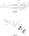
- the ring magnet 50 can be secured to the front end of the locking sleeve 256' which can be allowed to float in a forward direction to allow the ring magnet 50 to engage a fastener secured to the tool bit 40 received in a bore in the driven component 254 of the tool holder.
- Figure 21 illustrates the pivoting arrangement between the driving component and the driven component which, again, is detailed in U.S. Patent No. 7,942,426 , which is herein incorporated by reference in its entirety.
- the tool bit 300 includes a shaft having a hex-shaped shank 302 at a first end, and a working region 304 disposed at a second end.
- the shaft can have a section between the hex-shaped shank 302 and the working region 304 that has a reduced diameter region 306 that is disposed between two shoulders 308, 310.
- the reduced diameter region 306 provides a torsion zone that allows the shaft to twist to absorb forces while the tool bit 300 is being used to drive a fastener.
- a tool bit 300 having a torsion zone of this type is generally known in the art as disclosed by U.S. Patent No. 5,704,261 .
- the working region 304 of the tool bit 300 can be provided with various types of drive heads such as Phillips, flat, hex, square, and other known types of drive heads.
- a recessed groove 312 is provided in the working region 304 for receiving a retainer ring 314 therein.
- a ring magnet 50 is supported by a sleeve 316 that is retained on the tool bit 300 by the retainer ring 314 that is received within the recessed groove 312.
- the floating sleeve 316 is moved in a forward direction to allow the ring magnet 50 to engage the fastener to assist in retaining the fastener to the tool bit 300.
- the floating sleeve 316 includes an interior shoulder 318 that engages the retainer 314 to limit the sleeve's forward axial travel.
- the tool bit 300 includes a shoulder 320 at an end of the working region 304 that limits the axial travel of the floating sleeve 316 in the opposite direction.
- the floating sleeve 316 can optionally be removed from the tool bit 300 by pulling on the floating sleeve 316 in an axial direction to overcome the retainer 314.
- the retainer 314 can be a rubber O-ring or a steel hog ring that can be flexed inward when the floating sleeve 316 is either inserted onto or pulled off of the tool bit 300.
- the ring magnet 50 is supported by a floating sleeve 330 that is slidably received on a forward end of the tool bit 300.
- the floating sleeve 330 includes a plurality of axially extending fingers 332 that are integrally formed with the sleeve 330 and releasably engage the reduced diameter region of the tool bit between the two shoulders 308, 310.
- Figure 28 illustrates the floating sleeve 330 in a rearward position
- Figure 29 illustrates the floating sleeve 330 in a forward position for the ring magnet 50 to engage a fastener to help retain the fastener on the tool bit 300.
- the floating sleeve 330 can be removed from the tool bit by pulling forward on the floating sleeve 330, thus causing the fingers 332 to flex radially outward over top of the increased diameter portion at the head 304 of the tool bit 300.
- the floating sleeve 330 can be made from plastic, rubber, or other materials that allow flexibility of the fingers 332.
- the ring magnet 50 can be secured to the floating sleeve 330 by adhesives, in-molding, or other known fastening techniques.
- an alternative floating sleeve 340 design is shown for supporting a ring magnet 50 that can be received on a tool bit 300.
- the sleeve 340 includes a first end 342 supporting the ring magnet 50 and a second end 344 including a single elongated slot 346 that allows the second end 344 of the sleeve 340 to flex outward for insertion of a tool bit 300 therein.
- the interior of second end 344 of the sleeve 340 includes a plurality of radially inwardly extending tabs 348 that are received in the reduced diameter portion 306 of the tool bit 300 and engage the forward and rearward shoulders 308, 310 to limit axial movement of the sleeve 340 along the length of the tool bit 300.
- the floating sleeve 340 can be made from plastic or rubber
- a floating sleeve 350 can include a plastic cup 352 that receives the ring magnet 50 at a forward end thereof and a rubber sleeve 354 at a rearward end thereof.
- the interior surface of the rubber sleeve 354 includes a plurality of radially inwardly extending tabs 356 at its rearward end, as illustrated in phantom in Figure 31 .
- the radially inwardly extending tabs 356 are flexible to allow a tool bit 300 to be inserted into the sleeve 350 so that the tabs 356 engage the reduced diameter portion 306 between the forward and rearward shoulders 308, 310 of the tool bit 300.
- the sleeve 350 is allowed to float in a forward and rearward direction in the manner as described with regard to the above described embodiments.
- an alternative floating sleeve 360 design is provided in which a floating ring magnet 50 is supported at a first end of a rubber sleeve 360.
- the second end of the sleeve includes a plurality of radially inwardly extending tabs 362 that are flexible to allow a tool bit 300 to be inserted into the sleeve 360 wherein the tabs 362 are disposed in the reduced diameter portion 306 between the forward and rearward shoulders 308, 310 of the tool bit 300.
- the ring magnet 50 can be reinforced with a metal or plastic cap 364 disposed between the ring magnet 50 and the first end of the rubber sleeve 360.
- an alternative floating sleeve 370 is provided for supporting a ring magnet 50 in a forward end 372 thereof.
- the floating sleeve 370 can be made from plastic and can include one or more flexible fingers 374 that engage the reduced diameter portion 306 of the tool bit 300 between the forward and rearward shoulders 308, 310 thereof.
- the fingers 374 can include a radially inwardly protruding end portion 376 that engages the reduced diameter portion 306 of the tool bit 300.
- the elongated fingers 374 are integrally formed with the plastic sleeve 370 to allow the fingers 374 to flex radially outward when a tool bit 300 is inserted therein or removed therefrom.
- FIG. 37-39 an alternative arrangement of a floating sleeve 380 is provided wherein the flexible fingers 382 are made from a spring steel and are separately attached to the floating sleeve 380 which can be made from plastic or metal.
- the flexible fingers 382 operate in the same manner as the fingers 374 disclosed in Figures 33-36 to retain the floating sleeve 380 onto a tool bit 300 while allowing the sleeve 380 to float in a forward and rearward direction until the fingers 382 engage the forward or rearward shoulders 308, 310 of the tool bit 300.
- the fingers 382 include radially inwardly protruding portions 384 that engage the reduced diameter portion 306 of the tool bit 300.
- the flexible fingers 382 can be secured to the sleeve 380 by a rivet 386 or can be in-molded into the sleeve 380.
- the sleeve 380 includes a pair of opposing windows 388 to receive the fingers 382.
- an alternative floating sleeve 390 is provided for supporting a ring magnet 50 in a forward end thereof.
- the floating sleeve 390 can be made from plastic, rubber, or metal and can include a recessed annular groove 392 on an exterior surface thereof as well as a pair of oppositely disposed windows 394 that extend from the groove 392 into the interior of the sleeve 390.
- a rubber O-ring or a hog ring 396 can be provided in the annular groove 392 so as to extend into the window portion 394 of the annular sleeve 390 in such a manner that the O-ring or hog ring 396 can be received in the reduced diameter portion 306 of the tool bit 300 between the forward and rearward shoulders 308, 310 thereby retaining the floating sleeve 390 onto the tool bit 300.
- the reduced diameter portion 306 of the tool bit allows the floating sleeve 390 to move in a forward and rearward direction to allow the ring magnet 50 to engage a fastener for securing the fastener to the tool bit 300.
- FIG. 43-46 a still further alternative embodiment of the floating sleeve 400 is shown wherein the floating sleeve 400 supports a ring magnet 50 at a forward end and includes an exterior annular groove 402 with an opening 404 on one side that communicates to the interior of the sleeve 400.
- the annual groove 402 receives a D-shaped ring 406 having a generally flat portion 408 along one side thereof that is received in the window opening 404 of the annular groove 402 so that it communicates to the interior of the sleeve 400.
- the flat portion 408 of the D-shaped ring 406, as shown in Figure 46 is received in the reduced diameter portion 306 of the tool bit 300 between the forward and rearward shoulders 308, 310 to limit the axial movement of the floating sleeve 400 in the forward and rearward directions.
- the floating sleeve 410 includes an elongated annular recess 412 on an outer surface thereof and a plurality of window openings 414 extending therethrough within the elongated annular recess 412.
- the openings 414 each receive a ball 416 therein and a spring band 418 is received within the elongated annular recess 412 over top of the balls 416 to secure the balls 416 within the openings 414.
- the balls 416 are designed to be received in the reduced diameter portion 306 of the tool bit 300 between the forward and rearward shoulders 308, 310 to limit the axial movement of the floating sleeve 410 in the forward and rearward directions.
- the spring band 418 allows the balls 414 to be pushed radially outward against the spring force of the band 418 while the head of the tool bit 300 is inserted into, or removed from, the sleeve 410.
- the balls 416 move radially inward reducing the force of the spring band 418 on the balls 414. It is intended that the balls 414 provide an interference when engaging the forward and rearward shoulders 308, 310 of the reduced diameter portion 306, but do not provide significant resistance to the floating motion of the sleeve 410 along the tool bit 300.
- an alternative floating sleeve 420 is shown utilizing a single ball 422 wherein the spring band 424 is provided with an opening 426 therein for maintaining the position of the spring band 424 relative to the ball 422 that is received in the single opening 426 of the floating sleeve 420.
- the floating sleeve 430 supports a ring magnet 50 at a forward end thereof and includes a pair of lock jaws 432 that are pivotally mounted to the floating sleeve by pivots 434.
- the lock jaws 432 each include radially inwardly extending tabs 436 that are designed to be engaged within the reduced diameter portion 306 of the tool bit 300.
- the lock jaws 432 can be pivoted to an engaged position, as illustrated in Figure 54 , and a lock collar 438 can be pulled over top of the lock jaws 432, as illustrated in Figure 56 , to secure the lock jaws 432 to the tool bit 300.
- the ring magnet 50 is supported at the forward end of the floating sleeve 430 and the lockjaws 432 limit the axial movement of the floating sleeve 430 along the tool bit 300 to allow the ring magnet 50 to float to an engaged position when the tool bit 300 is engaged with a fastener.
- the lock collar 438 can be pulled in a forward position allowing the lock jaws 432 to be pivoted radially outward so that the tool bit 300 can be removed from the floating sleeve 430.
- the lock collar 438 can be made of a flexible material, or can have a rigid outer ring with a flexible material on the interior thereof that allows the lock collar 438 to be retained on the lock jaws 432 when they are in the locked position.
- an alternative floating sleeve 440 including a ring magnet 50 at a forward end of a plastic sleeve.
- the plastic sleeve 440 has a slot 442 therein and has exterior cam surfaces 444 thereon.
- a rotating sleeve 446 is engaged with the cam surfaces 444 of the sleeve 440 and the rotating sleeve 446 can be rotated to cause plastic sleeve 440 to be retained in a radially inward direction to positively engaged the radially inwardly extending tabs 448 of the sleeve 440 within the reduced diameter portion 306 of the tool bit 300 between the forward and rearward shoulders 308, 310 thereof.
- the rotating sleeve 446 can also be rotated to an unlocking position that allows the sleeve 440 to flex outwardly sufficiently enough to allow removal of the bit 300 from the floating sleeve 440.
- a floating sleeve 454 is provided with two interior ring magnets 456, 458 (as illustrated in Figure 58 with the sleeve 454 removed) which are positioned with both poles opposing one another at approximately 10mm apart. With both poles of the ring magnets 456, 458 opposing one another, the sleeve 454 will move freely along a length of the tool bit 452 as they are captured by the non-magnetic sleeve 454.
- An O-ring 460 can optionally be placed between the two magnets 456, 458 to provide resistance to movement of the floating sleeve 454 if so desired.
- the opposing poles of the magnets 456, 458 cause the sleeve 454 to float on the bit 450 until a face of the forward magnet 458 contacts a head of a fastener that has been placed on the driving end 462 of the tool bit 450. Once that contact is made, the sleeve 454 then positions itself such that the fastener remains in place on the bit 450 during installation. Once the faster is securely started, the sleeve 454 can be drawn back onto the bit 450 if desired where it will remain during the driving and seating of the fastener.
- a bit holder assembly 470 including a body 472 and a floating sleeve 474.
- the body 472 includes a first end defining a shank 476 and a second end defining a polygonal cavity 478 that can be hex-shaped or can have another polygonal shape.
- an additional bore 480 can be provided for receiving a magnet 482 therein.
- An exterior surface of the body 472 at the second end includes a threaded portion 484 which is adapted to receive a threaded cap 486.
- the threaded cap 486 includes interior threads 488 that engage the threaded portion 484.
- the threaded cap 486 also includes a radially inwardly extending shoulder 490 that captures an O-ring 492 axially between the shoulder 490 and an end surface 494 of the body 472.
- a radially inwardly extending shoulder 490 that captures an O-ring 492 axially between the shoulder 490 and an end surface 494 of the body 472.
- an annular groove 496 is formed having a forward shoulder 498.
- a shoulder 500 is formed for engagement with the shoulder 498 at the forward end of the annular groove 496. The shoulders 498, 500 limit the axial movement of the threaded cap 486 in the forward axial direction.
- the threaded cap 486 When a bit 40 (not shown) is inserted into the polygonal cavity 478, the threaded cap 486 can be tightened against the O-ring 492 causing the O-ring 492 to expand radially inwardly to engage the bit 40 and secure the bit 40 within the cavity 478. In order to remove the bit 40, the threaded cap 486 can be rotated to release the clamping force against the O-ring 492 thereby allowing the O-ring 492 to disengage the bit 40 and allow the bit 40 to be removed.
- the body 472 also includes an annular groove 502 located at an intermediate location along the body 472.
- the annular groove 502 is disposed in the exterior surface of the body and is elongated in the axial direction so as to receive a C-shaped hog ring 504 that is received in an annular recess 506 on the interior of the floating sleeve 474.
- the C-shaped hog ring 504 can travel axially along the length of the annular groove 502 to allow the floating sleeve 474 to float in a forward and rearward direction.
- the annular groove 502 has forward and rearward shoulders that limit the axial movement of the floating sleeve.
- the C-shaped hog ring 504 is flexible to allow removal of the floating sleeve 474 from the body 472 in order to gain access to the threaded cap 486 for tightening and loosening the cap 486 to allow insertion and removal of bits 40 from the polygonal cavity 478.
- a forward end of the floating sleeve 474 supports a ring magnet 50 that is allowed to move in forward and rearward directions to engage and magnetize a fastener to retain the fastener to the tool bit 40.
- a spacer sleeve 508 can be disposed rearward of the ring magnet 50 and can limit the rearward movement of the floating sleeve 474 by engagement with a forward end of the threaded cap 486.
- the shank 476 can be inserted into a drill either directly or indirectly via a quick release chuck device.
- the floating sleeve 474 can be removed from the body 472 and a bit 40 can be inserted into the polygonal cavity 478.
- the magnet 482 would attract the tool bit 40 to the rearward-most location within the polygonal cavity 478.
- the threaded cap 486 can then be tightened in the rearward direction R to cause the O-ring 492 to expand radially inward while being compressed and thereby engage the bit 40 and secure the bit 40 in the polygonal cavity 478.
- the floating sleeve 474 can then be slid over the end of the body 472 so that the C-shaped hog ring 504 is received within the annular groove 502 to limit the axial movement of the floating sleeve 474.
- a fastener 54 (not shown) is brought into engagement with the tool bit 40, the floating sleeve 474 under the influence of the ring magnet 50 can slide axially forward to engage the fastener 54 to thereby magnetize the fastener 54 and retain it to the bit 40.
- a bit holder assembly 470' may comprise the body 472, shank 476 and threaded cap 486 described above with a modified floating sleeve 474'.
- the floating sleeve 474' may include a retainer 504', such as an O-shaped or C-shaped elastic ring, that is received in the annular groove 502 on the exterior of the body 472 to allow the floating sleeve 474' to float between a forward position and a rearward position as limited by a forward shoulder 503 and a rearward shoulder 501 of the annular groove 502.
- the floating sleeve 474' supports a ring magnet 450 and that is allowed to move in forward and rearward directions to engage and magnetize a fastener to retain the fastener to the tool bit 40, as described above.
- the floating sleeve 474' differs from the floating sleeve 474 of Figure 61A in that there is no spacer 508 and the floating sleeve 474' can be moved further rearward to a parked position as shown in Figure 61B .
- the retainer 504' engages an outer wall of the body 472 (or a parking groove formed in the outer wall of the body 472). This exposes the threaded cap 486 to enable the threaded cap 486 to be removed from the body 472 without removing the floating sleeve 474' from the body 472.
- the floating sleeve 510 includes an elongated annular recess 512 on an outer surface thereof and a pair of tapered window openings 514 extending through the sleeve 510 opposite one another within the elongated annular recess 512.
- the window openings 514 each receive a ball 516 therein and a spring band 518 is received within the elongated annular recess 512 over top of the balls 516 to secure the balls 516 within the tapered window openings 514.
- the balls 516 are designed to be received in a reduced diameter portion 306 of the tool bit 300 between the forward and rearward shoulders 308, 310 to limit the axial movement of the floating sleeve 510 in the forward and rearward directions.
- the spring band 518 allows the balls 514 to be pushed radially outward against the spring force of the band 518 while the working region 304 of the tool bit 300 is inserted into, or removed from, the sleeve 510.
- the balls 516 move radially inwardly reducing the force of the spring band 518 on the balls 514. It is intended that the balls 514 provide an interference when engaging the forward and rearward shoulders 308, 310 of the reduced diameter portion 306, but do not provide significant resistance to the floating motion of the sleeve 510 along the tool bit 300.
- a ring magnet 50 is disposed at the forward end of the floating sleeve 510 and is designed to magnetize a fastener 54 (not shown) that is engaged to the bit 300.
- Figure 65 shows the floating sleeve 510 in a forward position while Figure 66 shows the floating sleeve 510 in a rearward position.
- the floating sleeve 510 can be received over the end of a double ended tool bit 900.
- the double ended tool bit 900 comprises a shaft 902 with a first working portion (e.g., a screwdriving head) 904 at a first end 906 and a second working portion (e.g., a screwdriving head) 908 at a second end 910.
- the shaft also includes a first reduced diameter portion 912 proximate the first working portion 904 and a second reduced diameter portion 914 proximate the second working portion 908.
- Each of the reduced diameter portions 912, 914 is defined by a front shoulder 916, 918 that is closer to the respective working portion 904, 908, and a rear shoulder 920, 922 that is further from the respective working portion 904, 908.
- the reduced diameter portions 912, 914 may function as torsion zones that reduce torsional stresses and breakage in the shaft 902.
- first and second shank portions 924, 926 Adjacent the first and second working portions 904, 908 are first and second shank portions 924, 926, each of which is disposed between the respective working portion 904, 908 and reduced diameter portion 912, 914.
- the shank portions 924, 926 each have a hex-shaped cross-section and are interrupted by an annular groove 928, 930.
- the first shank portion 924 is configured to be retained in a tool holder of a fastening tool when the second working region 908 is being used to drive a fastener.
- the second shank portion 926 is configured to be retained in a tool holder of a fastening tool when the first working region 904 is being used to drive a fastener.
- Disposed between the reduced diameter portions 912, 914 is an intermediate portion 932 also having a hex-shaped cross-section.
- the floating sleeve 510 is alternatively receivable over the first end 906 of the tool bit 900 ( FIG. 90A ) or the second end 910 of the tool bit 900 ( FIG. 90B ).
- the spring band 518 allows the balls 514 to be pushed radially outward against the spring force of the band 518 while the working region 904, 908 of the tool bit 900 is inserted into, or removed from, the sleeve 510.
- the balls 516 move radially inwardly reducing the force of the spring band 518 on the balls 514.
- the balls 514 provide an interference when engaging the forward shoulder 916, 918 and the rearward shoulder 920, 922 of the first and second reduced diameter portions 912, 914, but do not provide significant resistance to the floating motion of the sleeve 510 along the tool bit 900.
- the ring magnet 50 disposed at the forward end of the floating sleeve 510 floats forward to attract and magnetize the head of a fastener (not shown) that is engaged to the respective working region 904, 908 of the tool bit 900.
- FIG. 92 another embodiment of a double ended tool bit 900' to be used with the floating sleeve 510 includes a shaft 902' with a first working portion (e.g., a screwdriving head) 904' at a first end 906' and a second working portion (e.g., a screwdriving head) 908' at a second end 910'.
- the shaft includes a single reduced diameter portion 912' disposed equidistant between the first working portion 904' and the second working portion 908'.
- the reduced diameter portion 912' is defined by a first shoulder 916' that is closer to the first working portion 904' and a second shoulder 920' that is closer to the second working portion 908'.
- the reduced diameter portions 912', 914' may function as torsion zones that reduce torsional stresses and breakage in the shaft 902'.
- first and second shank portions 924', 926' Adjacent the first and second working portions 904', 908' are first and second shank portions 924', 926', each of which is disposed between the respective working portion 904', 908' and reduced diameter portion 912', 914'.
- the shank portions 924', 926' each have a hex-shaped cross-section and are interrupted by an annular groove 928', 930'.
- the first shank portion 924 is configured to be retained in a tool holder of a fastening tool when the second working region 908 is being used to drive a fastener.
- the second shank portion 926 is configured to be retained in a tool holder of a fastening tool when the first working region 904 is being used to drive a fastener.
- the floating sleeve 510 is alternatively receivable over the first end 906' or the second end 910' of the tool bit 900'. In either case, the balls 514 are received in the reduced diameter portion 912' and move between the first shoulder 916' and the second shoulder 920', which allows the sleeve 510 to float relative to the respective working region 904', 908' of the tool bit 900'.
- FIG. 93 another embodiment of a double ended tool bit 900" to be used with the floating sleeve 510 includes a shaft 902" with a first working portion (e.g., a screwdriving head) 904" at a first end 906" and a second working portion (e.g., a screwdriving head) 908" at a second end 910".
- the shaft also includes a first reduced diameter portion 912" proximate the first working portion 904" and a second reduced diameter portion 914" proximate the second working portion 908".
- Each of the reduced diameter portions 912", 914" is defined by a front shoulder 916", 918" that is closer to the respective working portion 904", 908", and a rear shoulder 920", 922" that is further from the respective working portion 904", 908".
- the reduced diameter portions 912", 914" may function as torsion zones that reduce torsional stresses and breakage in the shaft 902".
- first and second shank portions 924", 926 Adjacent the first and second working portions 904", 908" are first and second shank portions 924", 926", each of which is disposed between the respective working portion 904", 908" and reduced diameter portion 912", 914".
- the shank portions 924", 926" each have a hex-shaped cross-section and are interrupted by an annular groove 928", 930".
- the first shank portion 924" is configured to be retained in a tool holder of a fastening tool when the second working region 908" is being used to drive a fastener.
- the second shank portion 926" is configured to be retained in a tool holder of a fastening tool when the first working region 904" is being used to drive a fastener.
- the intermediate portion 932" Disposed between the reduced diameter portions 912", 914" is an intermediate portion 932" having a hex-shaped cross-section and a third reduced diameter portion 934".
- the third reduced diameter portion 934" may function as yet another torsion zone that reduces torsional stresses and breakage in the shaft 902".
- the floating sleeve 510 is alternatively receivable over the first end 906" or the second end 910" of the tool bit 900". In either case, the balls 514 are received in the reduced diameter portion 912" and move between the first shoulder 916" and the second shoulder 920", which allows the sleeve 510 to float relative to the respective working region 904", 908" of the tool bit 900".
- Figures 71-75 illustrate an alternative arrangement of the floating sleeve 530 which is arranged with the same construction as the floating sleeve 510 with different external dimensions and appearance. Accordingly, the same reference numerals used for describing the components of the floating sleeve 510 are used for the components of the floating sleeve 530 and a detailed description of the floating sleeve 530 is not believed to be necessary, other than to note that its dimensions are different from that of the ring magnet assembly 510 in order to be used with a different type of bit having a smaller working head region and/or longer reduced diameter portion.
- the tool bit assembly 550 includes a tool bit 552, a base collar 554 that is received on the tool bit 552, and a floating sleeve 556 that is slidably received on the base collar 554.
- a front end of the sleeve 556 is tapered inwardly. This intuitively prevents the user from attaching the sleeve backwards on the bit.
- the tool bit 552 can be of the type that includes a shank portion 558 and a working end 560 with a reduced diameter portion 561 and an annular groove 562 disposed in an intermediate location thereon.
- the tool bit 552' as shown in Figure 77 , can include recessed grooves at the corner edges of the hex-shaped shank 558 instead of the annular groove 562.
- the base collar 554 includes an internal recessed groove 568 that receives a retainer ring 570 therein.
- the retainer ring 570 is designed to be received in the annular groove 562 of the tool bit 552 or within the recessed grooves 564 of the alternative bit 552'.
- Retainer ring 570 secures the base collar to the tool bit 552, 552'.
- the base collar 554 includes a reduced diameter portion 572 having a recessed groove 574 in an outer surface thereof.
- a stop shoulder 576 is disposed at a rearward end of the reduced diameter portion 572.
- the floating sleeve 556 is movably received on the reduced diameter portion 572.
- the floating sleeve 556 includes an internal annular groove 578 that receives a retaining ring 580 received in the recessed groove 574. Retaining ring 580 limits the axial movement of the floating sleeve 556 via the forward and rearward shoulders 582, 584 of the annular groove 578. The rearward end 586 of the floating sleeve 556 engages the stop shoulder 576 of the base collar 554.
- a ring magnet 50 is received in a forward end of the floating sleeve 556 and is designed to magnetize a fastener to retain the fastener to the working head region 560 of the tool bit 552.
- the base collar 554' of the tool bit assembly 550 of Figures 76-81 has been modified to include an internal shoulder portion 590 that engages a forward shoulder 592 of the reduced diameter portion 561 of the tool bit 552.
- the shoulder portion 590 and the retainer ring 570 secure the base collar 554' relative to the tool bit 552 so that the movement of the floating sleeve 556 can be better controlled.
- Figures 82 and 84 show the modified base collar 554' engaged with alternative tool bits 552, 552'.
- a bit holder assembly 800 includes a body portion 820 coupled to a shank 840, and a floating sleeve 810 received over the body portion 820.
- the body portion 820 and shank 840 are similar to the sleeve 20 and connecting rod 40 of the bit holder described in U.S. Pat. App. Pub. No. 2012/0126497 , titled “Small Outer Diameter Quick Release Extension Rod,” which is incorporated herein by reference (“the '497 application”).
- the body 820 includes a socket 823 configured to receive a tool bit 40.
- a pair of lateral accommodation portions 832 is defined in a circumference of the socket 823.
- Each elongated elastic element 870 is sheet shaped and includes a body portion 871 connected between a pushed end portion 872 and an engaging end portion 873, which extends from the body portion 871 at an angle of approximately 45 ⁇ 15 degrees.
- An actuator sleeve 830 is received over the shank 840 and a rear end of the body 820 and is moveable axially relative to the body 820 and the shank 840.
- a return spring 860 is held axially by a first positioning ring 850 that is fixedly connected to the shank 840.
- the return spring 860 biases the actuator sleeve 830 toward a forward or locked position.
- the actuation sleeve 830 is fixedly connected to a second positioning ring 880.
- the second positioning ring 880 is fixedly connected to the pushed end portions 872 of the elongated elastic elements 871.
- the engaging end portions 873 of the elongated elastic elements 870 project into the socket 823 to engage and retain a tool bit 40 in the socket 823.
- the actuator sleeve 830 is retracted against the force of the return spring 860 (as shown in Fig. 6 of the '497 application)
- the second positioning ring 880 pulls the end portions 872 of the elongated elastic elements 870 to retract the engaging end portions 873 from the socket 823, enabling removal of the tool bit 40 from the socket 823.
- an ejection mechanism 890 Inside of the socket 823 is an ejection mechanism 890 includes a plunger 891, a magnetic element 892 and an elastic element 893.
- the magnetic element 892 is disposed on one end of the plunger 891, and the other end of the plunger 891 abuts against one end of the elastic element 893.
- the other end of the elastic element 893 abuts against an end of the connecting rod 840.
- the magnetic element 892 faces toward front end of the socket 823.
- the elastic element 893 When a tool bit is inserted into the socket 823, the elastic element 893 is compressed.
- the elastic element 893 pushes the plunger 891 toward the open end of the socket, causing at least partial ejection of the tool bit out of the socket 823. This helps enable removal of the tool bit from the socket 823.
- the magnetic element 892 prevents the tool bit from being fully ejected from the socket 823 when the actuator sleeve 830 is retracted to release the
- the outer surface of the body 820 is provided with an elongated annular recess 812.
- the floating sleeve 810 is substantially surrounds the body 820 and supports a ring magnet 814 at an end thereof.
- the floating sleeve 810 includes an interior annular groove 816 that receives a retainer 818 therein.
- the floating sleeve 810 can be removably attached to the body 820 by force fitting the body 820 into a rear opening 822 of the floating sleeve 810 until the retainer 818 is received in the recess 812 of the body 820.
- the recess 812 is provided with a forward shoulder 824 and a rearward shoulder 826 that allow the floating sleeve 170 to travel in a forward and rearward direction as indicated by arrow A while the shoulders 824 and 826 limit the travel of the floating sleeve 810 by engagement with the retainer member 818.
- the floating sleeve can float freely between a rear position, as shown in Fig. 87A , in which the retainer 818 engages the rear shoulder 826, and a front position as shown in Fig. 87B , in which the retainer 818 engages the front shoulder 824 and the ring magnet 814 can engage the head of a threaded fastener 819.
- the retainer 818 can take the form of a non-elastic member, such as a steel hog ring 818a, as shown in Figure 88A , or an elastic member, such as an elastic O-ring 818b as shown in Figure 88B or an elastic C-ring 818c as shown in Figure 88C .
- the floating sleeve 810 can also be moved rearward to a parked position in which the retainer 818 is positioned rearward of the rear shoulder 826.
- the retainer 818 comprises an elastic element (such as an elastic O-ring 818b or an elastic C-ring 818c) that is stretched and expands when the floating sleeve 810 is pulled axially rearward to the parked position.
- the expanded elastic retainer 818 frictionally engages the outer wall of the body portion 820 in a tight manner to maintain the floating sleeve 810 in the parked position until the user pulls the floating sleeve 810 forward back to one of the floating positions shown in Figures 87A and 87B .
- An internal shoulder 877 on the front end of the floating sleeve 810 abuts a front end 879 of the body portion 820 to prevent further rearward movement of the floating sleeve 810 beyond the parked position. In the parked position, it is easier for the user to grasp and remove the bit 40 when it is ejected from the socket 823 when the actuator sleeve 830 is retracted.
- the body portion 820 may be formed with an annular parking groove rearward of the annular recess 812 to more securely retain the retainer 818 and the floating sleeve 810 in the parked position.
- the tool bit 1010 is formed from a shaft 1016 having a polyogonal (e.g., hex-shaped) shank 1018 at a first end, and a fastening bit tip or working region 1020 disposed at a second end.
- the shank 1018 includes an annular groove 1019 that is configured to receive a retaining member in a bit holder of a power tool.
- the shaft 1016 includes the torsion zone 1011, which in this example, includes a pair of torsion sub-zones 1012, 1014 defined by a pair of reduced diameter regions disposed between two shoulders 1022, 1024 and an intermediate shoulder 1026.
- the pair of torsion sub-zones 1012, 1014 allow the shaft 1016 to twist to absorb forces while the tool bit 1010 is being used to drive a fastener.
- the torsion tool bit is particularly well suited for use with an impact tool that delivers drive impulses at high speeds and at high toque levels.
- the two torsion sub-zones 1012, 1014 can have the same or different lengths L1, L2 and the same or different diameters D1, D2, while the torsion zone 1011 has an overall length L.
- the working region 1020 of the torsion tool bit 1010 can be provided with a Phillips head fastening bit tip 1021 while other fastening bit tips such as a star tip 1070 (as shown in Fig. 14 ), flat, hex, square, and other known types of drive heads can also be used with a dual torsion zone and/or optimized torsion zone according to the principles of the present disclosure.
- a floating sleeve 1030 supporting a ring magnet 1032 at a forward end can be retained on the tool bit 1010.
- the floating sleeve 1030 may be similar to the floating sleeve 510 shown in FIGS. 64-70 .
- the floating sleeve 1030 includes an elongated annular recess 34 on an outer surface thereof and a pair of tapered window openings 1036 extending through the sleeve 1030 opposite one another within the region of the elongated annular recess 1034.
- the window openings 1036 each receive a ball 1038 therein and a spring band 1040 is received within the elongated annular recess 1034 over top of the balls 1038 to secure the balls 1038 within the tapered window openings 1036.
- the balls 1038 are designed to be received in the forward torsion zone 1012 of the tool bit 1010 between the forward and intermediate shoulders 1022, 1026.
- the length of the forward torsion zone 1012 can be designed to allow a desired amount of movement of the floating sleeve 1030 on the tool bit 1010.
- the ring magnet 1032 is disposed at a forward end of the floating sleeve 1030 and is designed to magnetize a fastener that is engaged to the fastening bit tip 1020.
- Other embodiments of floating magnet sleeves usable with the tool bit 1010 are disclosed elsewhere in this application.
- One or both of the torsion zones 1012, 1014 can be provided with an over-molded plastic or elastomeric branding strip or band 1050 that can include the company or product name or other information.
- the branding strip 1050 can extend over a predetermined length of the torsion zone(s) and can alternatively be in the form of an adhesive band.
- the present disclosure provides a method of designing the torsion bit 1010 with a torsion zone 1011 that is geometrically optimized for fatigue life when used with an impact driver.
- the optimization uses the principle of wave attenuation. More specifically, an energy wave can be attenuated as it travels through the torsion zone 1011. An energy wave in a fastening tool bit generated by modern powerful impact drivers delivers a large amount of torsional impact energy to the screw driving bit 1010. The amplitude of the energy wave may be far greater than what an ordinary fastening tool bit (even with a torsion zone) can handle, causing an ordinary fastening tool bit to break instantly, or at a low impact cycle count.
- the design optimization method uses a geometrically optimized torsion zone 1011 between the shank 1018 (starting point of the wave) and the fastening bit tip 1020 (end point of the wave).
- the torsion zone 1011 is used to attenuate the amplitude of the wave by dissipating at least some of the wave energy to elastically twist the torsion zone 1011.
- the torsion zone 1011 functions as a torsion spring.
- the simplest and most well understood mathematical model for the torsion zone 1011 is a cylinder.
- the torsion zone 1011 can comprise a single torsion zone (e.g., as disclosed in the embodiments of Figures 16-19 ) or a dual or multiple torsion sub-zones 1012/1014 (e.g., as disclosed in the embodiments of Figures 1-9 , 14 and 15 ).
- the intermediate shoulder 1026 between the torsion subzones 12/14 has little effect on the torsion spring properties of the overall torsion zone 1011. Instead, the main purpose of the intermediate shoulder 1026 is to provide a stop for the floating magnet sleeve.
- the torsion zone 1011 (whether single or multiple sub-zones) is mathematically modeled as a cylinder functioning as a torsion spring.
- the two dimensions to be optimized are the cylinder length (L) and its diameter (D) or radius (c), as illustrated in FIGS. 102 and 103 .
- PE spring potential energy of a torsion spring
- ⁇ twist angle
- Heat Q is the amount of heat generated is a function of the frequency of the energy wave (Ei n ) and the angle of twist ( ⁇ ). The higher the frequency and the higher the angle of twist, the higher the heat is expected to be.
- PE spring can be increased by either increasing k or increasing ⁇ .
- the present disclosure focuses on the fact that the ⁇ is inversely proportional to k (see Equation 3 below). In other words, as the spring constant k increases, ⁇ decreases. So both k and ⁇ are working against each other. The important thing to recognize is that ⁇ is squared in Equation 1, so it will dominate over k. Based on the above analysis, it is clear that the objective is to optimize length (L) and the cross sectional radius (c) (the torsion zone geometry) to achieve the highest angle of twist ⁇ .
- the geometric parameters L and c are arranged inside the parenthesis. For any given torque T, ⁇ will increase if the length L is increased, or the radius c is decreased. And, as discussed above, an increase in ⁇ will attenuate the input energy wave E in by converting more of the energy into spring potential PE spring and heat (Q).
- Equation 6 presents a simplified picture because the torque T is not a constant. In fact, torque T is a function of the spring constant k. Without knowing the relation between torque T and the spring constant k, then Equation 6 can only be used as a guide as to how to alter the parameters length L and radius c.
- the cycle life of the tool bit tends to be at a maximum.
- the fatigue life of the bit is directly related to the cross sectional areas of the torsion zone and the tip.
- the torsion zone fails first and when the stress on the tip area is higher than the stress on the torsion zone, the tip fails first.
- the maximum stress on the tip equals the maximum stress on the torsion zone, the bit reaches its optimal fatigue life.
- test samples were created using the above equations as a guide and the samples were tested.
- the experimental results are shown in the graph in FIG. 104A .
- the graph in Figure 104A is a plot of the spring constant k vs. cycle life (time in seconds) for a 2.5 inch tool bit with a Phillips #2 Head.
- the peak represents the optimized spring constant k where approximately half of the bits failed in the torsion zone and approximately half of the bits fail at the bit tip. It is anticipated that every bit-tip type and geometry will have a similar graph.
- the torsion zone length and diameter is tuned to the particular bit-tip geometry in-order to operate at the optimized peak where an approximate equal number of bits fail at the bit tip and at the torsion zone.
- the first torsion sub-zone 1012 had a length L1 in a range from approximately 8mm to approximately 12 mm, e.g. approximately 10 mm and a radius (c) in a range from approximately 1.6 mm to approximately 2.0 mm, e.g. approximately 1.8 mm and the second torsion sub zone 1014 had a length L2 in a range from approximately 10 mm to approximately 15 mm, e.g. approximately 12.5 mm and a radius (c) in a range from approximately 1.6 mm to approximately 2.0 mm, e.g. approximately 1.8 mm.
- FIG. 104B illustrates Table 6 of ISO 8764-1 which lists the minimum torque (M machine ) at which the driver tips shall not exhibit any fracture or permanent distortion.
- the optimized torsion zone must be able to transmit at least this minimal amount of torque to the bit tip. For example, for a type 2 Phillips tip a minimum torque of 10.3 N ⁇ m is required to be transmitted. If the optimized torsion zone for a particular bit tip does not satisfy this minimal ISO torque requirement, the bit design may need to be altered accordingly. There also may be a limit on how long the bit can be for user ergonomics.
- the graph in FIG. 105 shows the relative performance of the optimized 2.5 inch Phillips #2 screwdriver bit 1010 designed according to the principles discussed above versus other competitor Philips #2 torsion bit products.
- the vertical axis shows the run time in seconds until breakage of a tool bit that is installed in a test apparatus that simulates an impact driver driving a screw that is fully inserted.
- the optimized design according to the principles of the present disclosure averaged 91 seconds until breakage while the closest similarly sized competitor torsion bit lasted an average of 59 seconds until breakage.
- Other competitor torsion bit designs averaged even less time until breakage.
- a 1.5 inch torsion bit 1110 is shown including a torsion zone having dual torsion sub-zones 1112, 1114 separated by an intermediate shoulder 1126, similar to the 2.5 inch torsion bit 1010 shown in Figures 93-97 .
- the remaining reference numerals designate the same or similar elements as those referenced in Figures FIGS. 93-97 with a leading "11" instead of a leading "10".
- the floating sleeve 1130 has a design similar to the floating sleeve 170 in FIGS. 12A-12C , although it should be understood that the floating sleeve 1130 can be similar to any of the other floating sleeves disclosed elsewhere in this application.
- the torsion bit 1110 differs from the torsion bit 1010 in that the first torsion sub-zone 1112 has a length L1 that is shorter than a length L2 of the second torsion sub-zone 1112, with both torsion sub-zones 1112, 1114 having the same diameter D.
- the length L1 of sub-zone 1112 has been selected for desired movement of the above-described floating magnet sleeve 1130.
- the length L and diameter D of the torsion zone 1111 has been optimized according to the principles of the present disclosure. It should be noted that although a 1.5 inch and 2.5 inch torsion bit is shown, other lengths of torsion bits can be utilized with an optimized torsion zone (whether including one or multiple torsion zones) according to the principles of the present disclosure.
- a working region 1220 of a torsion tool bit 1210 can be provided with a star tip 1270 or other alternative shapes.
- the torsion tool bit 1210 is formed from a shaft 1216 having a polyogonal (e.g., hex-shaped) shank 1218 at a first end, and a fastening bit tip or working region 1220 disposed at a second end.
- the shank 1218 includes an annular groove 1219 that is configured to receive a retaining member in a bit holder of a power tool.
- the shaft 1216 includes the torsion zone 1211, which in this example, includes a pair of torsion sub-zones 1212, 1214 defined by a pair of reduced diameter regions disposed between two shoulders 1222, 1224 and an intermediate shoulder 1226.
- the pair of torsion sub-zones 1212, 1214 allow the shaft 1216 to twist to absorb forces while the tool bit 1210 is being used to drive a fastener.
- the torsion tool bit is particularly well suited for use with an impact tool that delivers drive impulses at high speeds and at high toque levels.
- the two torsion sub-zones 1212, 1214 can have the same or different lengths L1, L2 and the same or different diameters D1, D2, while the torsion zone 11 has an overall length L.
- a double ended tool bit 1310 including a shaft 1312 with a first working portion (e.g., screwdriving head) 1314 at a first end and a second working portion (e.g., a screwdriving head) 1316 at a second and.
- the shaft 1312 includes a torsion zone 1311 having three reduced diameter torsion sub-zones 1318A-1318C.
- the combined torsion zones 1318A-1318C can be optimized with the overall torsion zone 1311 having a combined length (L) and diameter (d) that have been optimized according to the method of the present disclosure, as described above.
- the torsion sub-zones 1318A, 1318C are of equal length and are longer than the torsion sub-zone 1318B.
- the torsion sub-zone 1318B can be provided with a shrink band 1320 for branding.
- a pair of ball grooves 1320 are disposed adjacent to the tips 1314, 1316 which are used for securing the bit 1310 within a bit holder or chuck.
- the ball grooves are of a shorter length and a shallower depth that the sub-torsion zones 1318A, 1318B, 1318C.
- a nut setter bit 1410 including a shaft 1412 having a working end 1414 having a recessed cavity 1416 for receiving a hex head of a screw or a nut and a shank 1418.
- a reduced diameter torsion zone 1420 is disposed between the working end 1414 and the shank 1418.
- the torsion zone 1420 has a length (L) and diameter (d) that have been optimized according to the method of the present disclosure, as described above.
- a magnetic drive guide 1510 including a shaft 1512 having a shank 1514 at a first end and a bit receiving cavity 1516 at a second working end 1517.
- the second working end 1517 can be formed integral with or as a separate attachment to the shaft 1512.
- a magnet 1518 can be disposed within the cavity 1516 and a sliding sleeve 1520 can be slidably received on an outer surface of the working end for guiding an elongated screw received within the sleeve 1520.
- the shaft includes a reduced diameter torsion zone 1522.
- the torsion zone 1522 has a length (L) and diameter (d) that have been optimized according to the method of the present disclosure, as discussed above, with a bit received in the drive guide.
- bit holder 1610 and floating magnet sleeve 1620 is shown, which is similar to the bit holder 800 and floating magnet sleeve 810 shown in FIGS. 86-88C .
- the bit holder 1610 differs from the bit holder 800 in that it includes a shaft 1612 with a reduced diameter torsion zone 1622.
- the torsion zone 1622 has a length (L) and diameter (d) that have been optimized according to the method of the present disclosure with a bit received in the bit holder 1610.
- Figure 106 is a graph showing the run time until breakage of the bit holder 1610 when holding a Phillips #2 1-inch bit tip in the holder, as compared to several competitor bit holders.
- the average time until breakage for the optimized tool bit holder 1610 was 12.66 seconds (with far less variability) as compared to 10.53 seconds for the next closest design, with each of the remaining competitor designs having significantly less time until breakage.
- the length and diameter of the torsion zones in the other disclosed embodiments of tool bits and tool bit holders may be optimized according to the method of the present disclosure, as described above.
Applications Claiming Priority (2)
| Application Number | Priority Date | Filing Date | Title |
|---|---|---|---|
| US201562249403P | 2015-11-02 | 2015-11-02 | |
| US15/296,546 US10150205B2 (en) | 2012-02-15 | 2016-10-18 | Fastening tools with floating magnet sleeves |
Publications (1)
| Publication Number | Publication Date |
|---|---|
| EP3162506A1 true EP3162506A1 (de) | 2017-05-03 |
Family
ID=57240898
Family Applications (1)
| Application Number | Title | Priority Date | Filing Date |
|---|---|---|---|
| EP16196701.3A Pending EP3162506A1 (de) | 2015-11-02 | 2016-11-01 | Befestigungswerkzeuge mit beweglichen magnethülsen |
Country Status (1)
| Country | Link |
|---|---|
| EP (1) | EP3162506A1 (de) |
Cited By (1)
| Publication number | Priority date | Publication date | Assignee | Title |
|---|---|---|---|---|
| CN112045613A (zh) * | 2019-06-05 | 2020-12-08 | 施耐宝公司 | 棘轮工具的带槽的传动器 |
Citations (10)
| Publication number | Priority date | Publication date | Assignee | Title |
|---|---|---|---|---|
| US5704261A (en) | 1992-12-22 | 1998-01-06 | Wera Werk Hermann Werner Gmbh & Co. | Torque-transmitting tool |
| US5988957A (en) | 1998-12-21 | 1999-11-23 | Black & Decker Inc. | Quick clamp |
| US6261035B1 (en) | 1998-11-12 | 2001-07-17 | Black & Decker Inc. | Chuck, bit, assembly thereof and methods of mounting |
| US6929266B2 (en) | 2002-06-18 | 2005-08-16 | Black & Decker Inc. | Bit holder |
| US7086813B1 (en) | 1998-06-26 | 2006-08-08 | Black & Decker Inc. | Quick-acting tool bit holder |
| US7942426B2 (en) | 2006-07-12 | 2011-05-17 | Black & Decker Inc. | Pivotal/rigid accessories for power and hand tools |
| US20120126497A1 (en) | 2010-11-23 | 2012-05-24 | Ying-Mo Lin | Small outer diameter quick release extension rod |
| EP2628570A2 (de) * | 2012-02-15 | 2013-08-21 | Black & Decker Inc. | Schnellwechsel-Bithalter mit Ringmagnet |
| US20130328276A1 (en) * | 2012-02-15 | 2013-12-12 | Black & Decker Inc. | Quick Change Bit Holder With Ring Magnet |
| US20140333037A1 (en) * | 2012-02-15 | 2014-11-13 | Black & Decker Inc. | Bit holder with floating magnet sleeve |
-
2016
- 2016-11-01 EP EP16196701.3A patent/EP3162506A1/de active Pending
Patent Citations (10)
| Publication number | Priority date | Publication date | Assignee | Title |
|---|---|---|---|---|
| US5704261A (en) | 1992-12-22 | 1998-01-06 | Wera Werk Hermann Werner Gmbh & Co. | Torque-transmitting tool |
| US7086813B1 (en) | 1998-06-26 | 2006-08-08 | Black & Decker Inc. | Quick-acting tool bit holder |
| US6261035B1 (en) | 1998-11-12 | 2001-07-17 | Black & Decker Inc. | Chuck, bit, assembly thereof and methods of mounting |
| US5988957A (en) | 1998-12-21 | 1999-11-23 | Black & Decker Inc. | Quick clamp |
| US6929266B2 (en) | 2002-06-18 | 2005-08-16 | Black & Decker Inc. | Bit holder |
| US7942426B2 (en) | 2006-07-12 | 2011-05-17 | Black & Decker Inc. | Pivotal/rigid accessories for power and hand tools |
| US20120126497A1 (en) | 2010-11-23 | 2012-05-24 | Ying-Mo Lin | Small outer diameter quick release extension rod |
| EP2628570A2 (de) * | 2012-02-15 | 2013-08-21 | Black & Decker Inc. | Schnellwechsel-Bithalter mit Ringmagnet |
| US20130328276A1 (en) * | 2012-02-15 | 2013-12-12 | Black & Decker Inc. | Quick Change Bit Holder With Ring Magnet |
| US20140333037A1 (en) * | 2012-02-15 | 2014-11-13 | Black & Decker Inc. | Bit holder with floating magnet sleeve |
Cited By (2)
| Publication number | Priority date | Publication date | Assignee | Title |
|---|---|---|---|---|
| CN112045613A (zh) * | 2019-06-05 | 2020-12-08 | 施耐宝公司 | 棘轮工具的带槽的传动器 |
| US11548125B2 (en) | 2019-06-05 | 2023-01-10 | Snap-On Incorporated | Grooved drive for ratchet tools |
Similar Documents
| Publication | Publication Date | Title |
|---|---|---|
| US10150205B2 (en) | Fastening tools with floating magnet sleeves | |
| US10556329B2 (en) | Tool bits with floating magnet sleeves | |
| US9505108B2 (en) | Bit holder with floating magnet sleeve | |
| EP2628570B1 (de) | Schnellwechsel-Bithalter mit Ringmagnet | |
| US9227309B2 (en) | Quick change bit holder with ring magnet | |
| EP2837468B1 (de) | Bithalter mit beweglicher Magnethülse | |
| US20060254394A1 (en) | Fastener driver | |
| EP1803515B1 (de) | Universaler Schaft für ein Werkzeug oder für einen Einsatz | |
| EP2431129B1 (de) | Werkzeugteil oder Werkzeughalter für eine Werkzeugmaschine | |
| US9352455B2 (en) | Fastener driver and extension | |
| US20150102567A1 (en) | Tool joint | |
| US20090174157A1 (en) | Tool connecting device | |
| US7563061B2 (en) | Self-centering drill bit chuck | |
| US7174812B1 (en) | Driving tool having fastener retaining device | |
| EP3009234B1 (de) | Werkzeugteile mit beweglichen magnethülsen | |
| US8770069B2 (en) | Automatically-configurable screwdriver assembly | |
| EP3162506A1 (de) | Befestigungswerkzeuge mit beweglichen magnethülsen | |
| US10792793B2 (en) | Tool bits with floating magnet sleeves | |
| CN109202798A (zh) | 螺丝刀 | |
| US11607779B2 (en) | Shaft spring clutch apparatus | |
| WO2018106976A1 (en) | Anti-marring bit holder | |
| CN116619281A (zh) | 一种爪式螺丝刀 |
Legal Events
| Date | Code | Title | Description |
|---|---|---|---|
| PUAI | Public reference made under article 153(3) epc to a published international application that has entered the european phase |
Free format text: ORIGINAL CODE: 0009012 |
|
| STAA | Information on the status of an ep patent application or granted ep patent |
Free format text: STATUS: THE APPLICATION HAS BEEN PUBLISHED |
|
| AK | Designated contracting states |
Kind code of ref document: A1 Designated state(s): AL AT BE BG CH CY CZ DE DK EE ES FI FR GB GR HR HU IE IS IT LI LT LU LV MC MK MT NL NO PL PT RO RS SE SI SK SM TR |
|
| AX | Request for extension of the european patent |
Extension state: BA ME |
|
| STAA | Information on the status of an ep patent application or granted ep patent |
Free format text: STATUS: REQUEST FOR EXAMINATION WAS MADE |
|
| 17P | Request for examination filed |
Effective date: 20171101 |
|
| RBV | Designated contracting states (corrected) |
Designated state(s): AL AT BE BG CH CY CZ DE DK EE ES FI FR GB GR HR HU IE IS IT LI LT LU LV MC MK MT NL NO PL PT RO RS SE SI SK SM TR |
|
| STAA | Information on the status of an ep patent application or granted ep patent |
Free format text: STATUS: EXAMINATION IS IN PROGRESS |
|
| 17Q | First examination report despatched |
Effective date: 20210325 |
|
| STAA | Information on the status of an ep patent application or granted ep patent |
Free format text: STATUS: EXAMINATION IS IN PROGRESS |