EP2429828B1 - Method of printing - Google Patents
Method of printing Download PDFInfo
- Publication number
- EP2429828B1 EP2429828B1 EP10719059A EP10719059A EP2429828B1 EP 2429828 B1 EP2429828 B1 EP 2429828B1 EP 10719059 A EP10719059 A EP 10719059A EP 10719059 A EP10719059 A EP 10719059A EP 2429828 B1 EP2429828 B1 EP 2429828B1
- Authority
- EP
- European Patent Office
- Prior art keywords
- ink
- passes
- dose
- printed
- radiation
- Prior art date
- Legal status (The legal status is an assumption and is not a legal conclusion. Google has not performed a legal analysis and makes no representation as to the accuracy of the status listed.)
- Active
Links
Images


Classifications
-
- B—PERFORMING OPERATIONS; TRANSPORTING
- B41—PRINTING; LINING MACHINES; TYPEWRITERS; STAMPS
- B41M—PRINTING, DUPLICATING, MARKING, OR COPYING PROCESSES; COLOUR PRINTING
- B41M7/00—After-treatment of prints, e.g. heating, irradiating, setting of the ink, protection of the printed stock
- B41M7/0081—After-treatment of prints, e.g. heating, irradiating, setting of the ink, protection of the printed stock using electromagnetic radiation or waves, e.g. ultraviolet radiation, electron beams
-
- B—PERFORMING OPERATIONS; TRANSPORTING
- B41—PRINTING; LINING MACHINES; TYPEWRITERS; STAMPS
- B41J—TYPEWRITERS; SELECTIVE PRINTING MECHANISMS, i.e. MECHANISMS PRINTING OTHERWISE THAN FROM A FORME; CORRECTION OF TYPOGRAPHICAL ERRORS
- B41J11/00—Devices or arrangements of selective printing mechanisms, e.g. ink-jet printers or thermal printers, for supporting or handling copy material in sheet or web form
- B41J11/0015—Devices or arrangements of selective printing mechanisms, e.g. ink-jet printers or thermal printers, for supporting or handling copy material in sheet or web form for treating before, during or after printing or for uniform coating or laminating the copy material before or after printing
- B41J11/002—Curing or drying the ink on the copy materials, e.g. by heating or irradiating
-
- B—PERFORMING OPERATIONS; TRANSPORTING
- B41—PRINTING; LINING MACHINES; TYPEWRITERS; STAMPS
- B41M—PRINTING, DUPLICATING, MARKING, OR COPYING PROCESSES; COLOUR PRINTING
- B41M7/00—After-treatment of prints, e.g. heating, irradiating, setting of the ink, protection of the printed stock
- B41M7/0072—After-treatment of prints, e.g. heating, irradiating, setting of the ink, protection of the printed stock using mechanical wave energy, e.g. ultrasonics; using magnetic or electric fields, e.g. electric discharge, plasma
-
- B—PERFORMING OPERATIONS; TRANSPORTING
- B41—PRINTING; LINING MACHINES; TYPEWRITERS; STAMPS
- B41M—PRINTING, DUPLICATING, MARKING, OR COPYING PROCESSES; COLOUR PRINTING
- B41M3/00—Printing processes to produce particular kinds of printed work, e.g. patterns
- B41M3/008—Sequential or multiple printing, e.g. on previously printed background; Mirror printing; Recto-verso printing; using a combination of different printing techniques; Printing of patterns visible in reflection and by transparency; by superposing printed artifacts
Definitions
- This invention relates to printing using a curable printing medium.
- Examples of the invention relate to the printing using curable printing materials, including, without limitation, curable ink.
- aspects of the invention find particular application in the printing of images using ink, but are also applicable more widely to the printing of any curable material onto a substrate.
- Particular aspects of the invention relate to the printing of material onto a substrate in which the printed material has a particular surface structure or appearance.
- Some aspects relate to methods of printing images having a varied surface structure, appearance or gloss.
- Aspects of the invention relate to the printing of images which are wholly or partly glossy. Aspects of the invention find application in printing using an inkjet printer.
- curable print materials in printing is well known.
- Curable inks typically solidify by reaction, for example by polymerisation and/or crosslinking, on exposure to radiation.
- UV curable inks which cure on exposure to UV light.
- Curable inks are commonly used in inkjet printing processes, in which droplets of ink are emitted from the nozzles of an inkjet printhead that is moved relative to a substrate. The droplets of ink contact the substrate and are subsequently cured, commonly using a radiation source.
- the printed image is typically built up in successive scans or passes of one or more printheads relative to the substrate. Ink laid down in subsequent scans or passes is deposited onto the substrate and/or onto previously laid down ink deposited in previous passes.
- the surface appearance, for example gloss level, of the printed image may be changed by selecting the power emitted by the radiation source on different passes.
- the radiation source is typically operated at a constant high power (e.g. full power) throughout the printing process, giving a relatively rough, and therefore matt, surface.
- a matt finish is required, the radiation source is typically operated at a constant high power (e.g. full power) throughout the printing process, giving a relatively rough, and therefore matt, surface.
- the radiation source is operated at a lower power (for example at 5% power), causing the ink to partially cure.
- partially cured ink has a non-solidified surface allowing greater wetting of the surface by ink droplets that are applied in a subsequent pass, leading to a flatter and/or less rough final surface and a glossier finish to the print.
- the radiation source can then be switched to a higher power (for example full 100% power) for one or more additional passes to fully cure the ink film, thereby rendering the surface relatively glossy.
- the white areas in the final image will normally contain little or no ink and consequently will have a gloss level or surface finish similar to that of the substrate.
- differential gloss levels may result across the surface of the image, particularly where a substrate having a matt finish is employed for the printed image.
- WO-A1-2008/129298 describes a large scale ink jet printer having an array of print heads substantially the full width of the image to be printed.
- WO-A1-2008/068211 describes a multi-pass curing method for an inkjet printing apparatus.
- the dose is measured as energy per unit area applied to the printed ink (for example measured in J/m2).
- Alternative methods for determining the dose could be used, where appropriate.
- the first dose range and the second dose range are such that the curing effected of the printed ink in the first set of passes is different from the curing effected of the printed ink of the second set of passes, and
- the first dose and the second dose are such that the surface finish of the printed ink of the first set of passes is different from the printed ink of the second set of passes.
- the ink of one set is more glossy than that of the other set, the other ink being more matt.
- the radiation source of the first set may be the same or different from that of the second set.
- the power output of the source may be adjustable.
- the use of different sources having different power outputs will be preferred. Other options are described below.
- the first set and/or the second set preferably include a plurality of passes comprising deposition of ink.
- the desired image is formed, and it is also possible in some examples to achieve the desired surface effects.
- the matt surface effect is preferably formed by depositing ink onto a previously deposited, and fully cured, layer of ink.
- a matt surface can be built up in a plurality of passes. It is thought that the use of a plurality of passes is less important for the formation of a gloss finish, but in practice in many examples, a plurality of passes will be desirable to build up the image on the substrate at the desired print resolution.
- one of the first set and the second set of passes effects partial cure of the ink, the other effecting substantially full cure of the ink.
- the curing step is carried out such that the upper or exterior surface of the partially cured material is not solidified, and preferably is in liquid and/or gel form.
- the external surface of the partially cured material is such that a subsequent layer of print material applied to the partially cured material will wet the partially cured layer.
- a more glossy surface can be obtained compared with methods in which a subsequent layer of ink is applied to a substantially solidified layer. Examples of methods for carrying out a partial cure are described in International Patent Application No. WO2004/002746 . Examples of radiation sources for carrying out partial curing and/or full curing are described in International Patent Application No. WO2004/056581 .
- the dose of the emitted radiation one of the first set of passes and the second set of passes may be less than about 20% or less than about 10%, preferably about 5% or less of the dose of the emitted radiation of the other set of passes.
- the power of the emitted radiation of one set may be less than about 20%, or less than about 10% preferably less than 5% of the power of the other set.
- the lower dose of radiation can effect partial curing in some examples. It will be appreciated that the dose of the radiation emitted in each of the passes of a set might not all be the same, but preferably the range of dose emitted is lower in one set than in the other set, preferably the upper value of the lower range is less than 20%, or less than about 10% of the lower value of the upper range.
- one of the surface finishes is more glossy than the other, more matt, one to give regions of the printed substrate different surface finishes.
- a glossy logo could be provided on a matt background.
- the first set of passes effects sprinting of ink onto a first region of the substrate
- the second set of passes effecting printing of ink onto a second region of the substrate different from the first region
- the first and/or second sets of passes may of course effect printing onto a plurality of different areas of the substrate. There may be overlap between the first and second regions so that some regions are printed in both the first set and the second set of passes. In some examples, this would be less preferred as it may lead to the use of additional ink compared with examples of less overlap. However, in other arrangements, such an overlap will be preferred, for example to achieve the desired surface effects. Such examples are described in more detail below.
- the method may further include a transitional set of passes between the first and second sets of passes, the transitional set of passes including one or more ink deposition passes and/or one or more passes including emitting radiation from a radiation source.
- first curing mode it is possible to have an "overlap" between a first curing mode and second curing mode as discussed further below.
- further printing and/or curing passes may be provided before, between, or after the passes of the first and/or second set, as desired.
- Each set of passes may include one or more passes.
- a single radiation source, or multiple radiation sources could be used, as appropriate.
- the first set of passes may include emitting radiation having a relatively lower dose to effect partial curing of the ink, and the second set of passes include emitting radiation having a relatively higher dose to effect substantially full cure of the ink.
- first and second sets of passes of ink are deposited in different areas, this can give rise to glossy regions and matt regions of the printed substrate.
- glossy regions formed in the first passes can be made to look more matt by reason of the addition of ink from the second passes.
- the gloss areas are printed first, because the partially cured ink of the gloss printing can be further cured during the subsequent curing of the ink of the matt printing.
- the method may include a transitional pass including the deposition of ink onto regions including partially cured ink, and onto regions not including partially cured ink, and emitting radiation to effect substantially full cure of the ink on the regions including partially cured ink, and onto the regions not including partially cured ink.
- the transitional pass comprises an "overlap" of the last pass of the printing of the gloss print, and the first pass of the printing of the matt print.
- the high dose radiation can be applied to the whole printed region, and effects both cure of the gloss and matt areas.
- a separate final "partial curing" pass for the gloss print can be avoided, thus increasing efficiency of the printing, by reducing the number of passes required.
- Print material may be printed onto the second portion prior to, concurrently with or after printing of print material onto the first portion of the substrate.
- print material is printed onto the second portion after print material on the first portion has been partially cured, and optionally after further print material has been printed onto said first portion.
- print material is printed onto said second portion prior to printing print material on said first portion.
- Ink of the second set of passes may be printed onto ink deposited in the first set of passes.
- the surface finish of the ink deposited can be further controlled.
- the relatively glossy surface can be changed during the second set of passes by applying a relatively matt surface onto it in one or more regions.
- Ink of the first and/or second set of passes may include substantially transparent or translucent ink or varnish.
- one or more passes of the second set of passes includes printing at least a part of the pass using translucent or transparent ink. It will be appreciated that other surface effects could be provided by printing using different print materials.
- varnish, transparent or translucent ink or other printing material could be used to make a matt print more glossy.
- the area of the substrate onto which print material is printed may be the whole or part of the substrate.
- the printer is a digital inkjet printer.
- the printheads of the printer extend substantially the full width of the substrate being printed.
- the printer is a full width printer, although other arrangements are possible and aspects of the invention described herein are applicable to a wide range of different printers.
- the printer is a flatbed printer.
- the ink is preferably UV curable ink and the radiation source includes a UV radiation source.
- one of the surface finishes is more glossy than the other.
- a method in which the image to be printed includes heavy print areas for which a relatively high dose of ink is to be deposited and further includes light print areas for which a relatively low dose of ink is to be deposited, the method comprising:
- the additional ink deposited does not change the appearance of the print significantly other than the surface finish.
- the additional ink has a colour similar to that of the substrate, or is translucent or transparent.
- the additional ink may be white, or may comprise a varnish.
- the additional ink may be printed in the same pass as ink of the image.
- the additional ink may be printed in one or more of the existing printing passes for printing the image, and/or separate printing passes may be added to print the additional ink. If the light area is to be matt, or gloss, the additional ink is preferably printed as a part of the relevant first or second set of passes.
- the method of the invention may be used to print an image comprising a portion which is substantially white.
- a substantially white or colourless print material may be printed onto said portion of the substrate and cured. In this way, the gloss level of the portion can be controlled such that there is less variation in relation to the remainder of the printed image.
- the methods disclosed herein are generally applicable to a wide variety of ink-jet printers.
- Features of the method are suitable where a continuous array of printhead nozzles is provided as in the inkjet printers, so that the printed image can be built up in layers.
- the curable print material used in the methods disclosed herein is preferably a curable ink, in particular a UV curable ink.
- the term "ink” should be interpreted broadly to include any appropriate printing material to be deposited on the substrate.
- the ink has low volatility.
- the substrate and the ink are such that there is little absorption of the ink into the substrate.
- a substantial proportion of the deposited ink remains on the substrate, preferably on the surface of the substrate.
- preferably at least 50%, more preferably at least 60%, 70%, 80% or at least 90% of the ink remains on the substrate, preferably on the surface of the substrate. This is to be contrasted with solvent-based inks where only a small amount of the ink deposited remains on the substrate.
- a radiation source may comprise one or more elements, for example one or more mercury lamps or LEDs.
- a radiation source extends across the full width of the image being printed, and preferably across the full printable width of the substrate. In other arrangements, smaller radiation sources may be used.
- a method requires the application of different doses of radiation, this may achieved in various ways, for example using a different number of sources, a different power input to the sources, a different configuration of sources, or by turning off one or more elements of the sources or by varying the relative speed of the source and the substrate.
- one or more radiation sources may be used.
- different radiation sources may be used for the first and second curing steps.
- one source may comprise a subset of another source and/or an altered version of another source.
- the printer may include one or more radiation sources having a baffle, a screen or a shutter.
- baffles, screens or shutters can effectively change the dose of radiation received at the substrate for curing the ink. Screens or shutters are thought to be particularly useful in the case where the first dose is required to be less than 20%, less than 10% or about 5% of the further dose. It is difficult to control the power input to a radiation source to be less than 10% of power, as the source (particularly in the case of mercury lamps) may have a tendency to turn off. In some cases, turning radiation sources on and off to obtain the required radiation dose is also not an attractive option because some sources take some considerable time to warm up from being off to being ready for use.
- the use of movable shutters provides a potentially simple but effective solution. Where a plurality of radiation sources are used, each radiation source may comprise a baffle or screen in a different configuration.
- the speed of relative movement of the radiation source and the substrate during the first and further curing steps may be different. In this way, different curing doses can be obtained for each curing step. In some cases the same radiation source, operating at the same power, could be used for both steps, the different dose being delivered by means of selecting an appropriate speed of relative movement of the radiation source and substrate.
- the percentage of the effective dose of the radiation (for example, the dose or curing energy per unit area received at the substrate) in a first curing step compared with a further curing step may be, for example, determined by consideration of the relative power outputs of the radiation sources used for the first and further curing steps, preferably taking into account the effect of any baffles or screens and the like, and the relative speed of movement of the source and substrate. In some cases, in particular where the speed of relative movement between the printheads and the substrate is the same for the first and any further curing steps, it may be convenient to consider the relative doses of radiation to be equivalent to the dose of radiation emitted by the radiation source in the first and further curing steps.
- the wavelength of the radiation used in a partial curing step is greater than about 370 nm, preferably approximately between 380 nm and 420 nm, and more preferably approximately between 385 nm and 400 nm.
- the phrase "wavelength" preferably connotes a nominal wavelength, for example as might be used by manufacturers to identify a type of curing lamp, or by reference to the most dominant wavelength in a group of wavelengths emitted by a given radiation source, for example.
- the wavelength of the radiation used in a partial curing step may even be greater than about 420 nm, for example using different colours of the visible and infrared spectrum.
- the desired wavelength will depend on the type of ink used, in particular the curing initiators used in the ink. However, the use of relatively long wavelengths will tend to cure the part of the drop adjacent the surface more than the exposed surface, which is desirable in that it can aid immobilisation of the drop on the substrate.
- the long wavelength radiation is thought to be more penetrating into ink drops close to the substrate and thus effect cure deep in the droplets.
- one or more curing steps may be conducted in the presence of an inerting or low oxygen environment, for example a nitrogen inerting environment.
- an inerting or low oxygen environment for example a nitrogen inerting environment.
- a nitrogen inerting environment there are several ways in which to achieve this.
- Using a local nitrogen atmosphere can reduce the inhibition of the free radical reaction by the presence of oxygen, which diffuses into the ink surface.
- Mercury arc lamps overcome the effect of oxygen inhibition by emitting enough power such that the rate of free radical production exceeds the rate at which oxygen diffusion can inhibit the reaction. Whereas the need to use a nitrogen atmosphere adds complexity to the system, this is more than compensated by the other advantages described above.
- inerting is to be understood to include reference to an argument in which the inerting gas or environment has the effect of reducing inhibition of cure of the ink.
- the inerting gas or environment may be itself inert, but in many cases it will be sufficiently inerting without itself being completely inert.
- a low-oxygen gas may provide an inerting environment.
- carbon dioxide gas and/or nitrogen gas may be used.
- the radiation used in any fully curing step preferably includes radiation having a wavelength less than the wavelength used in partial curing steps.
- this shorter wavelength radiation can overwhelm the oxygen inhibition effect at the surface and effect solidification of the ink at the surface.
- the radiation used in a full curing step includes radiation having a wavelength less than about 360 nm, preferably approximately between 300 nm and 350 nm, and more preferably approximately between 320 nm and 340 nm.
- the radiation used in the full curing step may include radiation having a wavelength greater than about 370 nm, preferably approximately between 380 nm and 420 nm, and more preferably approximately between 385 nm and 400 nm, for example by employing the same radiation source used in the partial curing step, preferably in addition to a further radiation source of shorter wavelength.
- the use of both short and long wavelengths afforded by this combination can effect the full cure within the ink as well as substantially at the surface of the ink.
- the method disclosed herein may include carrying out further printing passes and curing steps.
- the invention also provides an apparatus for carrying out the method described herein, said apparatus being defined in claim 12.
- FIGS 1a and 1b show schematically two examples of printing apparatus which can be used in examples described herein. The skilled person will understand that other printer arrangements could be used to carry out printing operations described herein.
- Figure 1a shows a part of an ink jet printer arranged to print an image 1 on a substrate 3.
- the printer includes a support beam 5, the support beam 5 and the substrate 3 mounted for relative movement in a printing direction A.
- the beam 5 and/or the substrate may be movable.
- the substrate 3 may be mounted on a movable substrate table or bed (not shown) in a known way.
- a printhead arrangement 7 is mounted on the beam 5 and includes a plurality of printheads 9 arranged in an appropriate array.
- the printhead arrangement further includes one or more radiation sources 11, 13 mounted adjacent the printheads upstream and/or downstream relative to the printing direction A.
- the number and arrangement of the radiation sources being chosen having regard to the printer arrangement and operation, for example as to whether bidirectional printing is to be used (in which case curing devices on both sides of the printheads are preferred), and whether a single radiation source or different radiation sources are to be used to generate the different power curing radiation.
- the image 1 is printed on the substrate 3 in a series of layers as the printhead arrangement 9 moves relative to the substrate 3 in the printing direction A.
- the printhead arrangement 9 is indexed in a direction perpendicular to the printing direction A so that the image can be printed onto the substrate.
- the printheads extend substantially the full width of the substrate; arrangements in which the printheads extend less than the full width are possible, in which case greater indexing of the printheads will be necessary to print the full area of the substrate.
- the radiation source 11, 13 is activated to emit radiation to cure the deposited ink.
- the wavelength and power of the radiation is chosen so as to produce the desired level of cure given the speed of relative movement of the source and the substrate.
- Figure 1b shows an alternative arrangement in which the image 1' is printed on the substrate 3' in a series of swathes as the printhead arrangement 9' moves relative to the substrate 3' in a scan direction perpendicular to the printing direction A. Between scans of the printhead 9', the beam 5' and substrate 3' move relative to each other in the printing direction A.
- the radiation source 11' on the printhead arrangement 7' is activated if a partial curing is being carried out. If a full cure is being carried out, a full substrate width radiation source mounted at the beam 5' is used. As the beam 5' indexes during printing, the radiation source passes over the full area of the printed substrate to cure the ink.
- the radiation sources may be any appropriate source having regard to the arrangement used and the nature of the material to be cured. In some arrangements mercury lamps could be used. As an alternative or in addition, arrays of LEDs or other radiation sources could be used for the partial cure and/or the full cure.
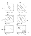
- Figures 2 to 5 illustrate four different methods for obtaining a printed surface having a controlled surface finish.
- Figures 2a and b and Figures 3a and b show the forming of a single gloss region 20 having a relatively glossy surface finish, the remainder of the printed image being a matt region 22 having a relatively less glossy surface finish.
- the regions to be glossy 28 are printed first in a first set of printing passes, and the matt areas are subsequently printed in a second set of printing passes.
- four printing passes are required to print the full image onto each area of the substrate.
- four printing passes are carried out to print ink into the area to be glossy 28.
- the radiation source emits a relatively low dose of radiation on the substrate including the printed area 20 so that each printed pass of ink in the gloss area 28 is partially cured after printing. In this way, a subsequent pass of ink printed onto the area wets the previously applied ink to give a low contact angle with the surface and thus a relatively glossy printed area 20.
- the radiation source applies a relatively high dose of radiation to the substrate. This high dose substantially fully cures the print deposited in each of the passes of the second set of passes.
- the radiation applied also acts to complete the cure of ink applied in the glossy area 20.
- ink laid down on a previously cured pass has a low contact angle on the cured surface and thus a relatively matt surface is formed.
- An optional further curing pass may be carried out to ensure substantially full cure of the printed image.
- the same image may be printed using fewer than eight passes.
- a transitional set of passes is used. This set includes one pass in which ink is deposited both in the gloss region 28 and in the matt region 22 and a high dose cure is carried out. Because the ink deposited in the gloss region 28 is printed onto a partially cured layer, a gloss surface is formed and is fully cured in the transitional set. Because the ink printed in the matt region is printed onto the substrate and fully cured, this then forms the first pass of the matt printed area 22. The printing then follows with a second set of passes comprising three passes including deposition of ink onto the matt area 22, the ink being substantially fully cured after each pass. Thus four passes of ink have been applied to each area and the curing carried out to produce a gloss region 20 and a matt region 22 using only seven passes.
- the gloss regions printed in the first set of passes may be preferred for the gloss regions printed in the first set of passes to extend slightly into the area to be matt, the matt regions being printed onto this overlap region to give a better interface between the areas.
- the method illustrated in Figures 3a and 3b is similar to that of Figures 2a and 2b , except that the regions to be matt 22 are printed first in the first set of printing passes, the gloss region 20 being printed in the second set of printing passes.
- the image is formed in four printing passes for each printed area.
- ink is deposited in the areas to be matt 22 and each pass of ink is substantially fully cured to form the matt surface.
- the regions to be gloss are printed and a partial cure is carried out after each pass of ink is deposited to form a relatively gloss surface.
- one or more further curing passes are carried out at high dose to effect substantially full cure of the ink on the substrate.
- FIG. 4a and 4b A further alternative is shown in Figures 4a and 4b in which an image is produced in which a glossy surface 25 has areas of matt surface finish 24.
- a first set of printing passes passes of ink are deposited, each followed by a partial cure at relatively low dose to form a glossy surface 23.
- a subsequent second set of passes further ink is deposited in one or more regions 24, the ink being substantially fully cured after each printing pass to form regions 24 having a relatively matt surface.
- the ink in the glossy areas also achieves substantially full cure.
- substantially the full surface is covered with the second set of printing passes, so that the overall surface texture of the image can be controlled.
- the second set of printing passes By controlling for example the distribution of ink of the second set of passes and the curing regime, relatively close control of the resulting surface finish can be achieved.
- covering a gloss underlayer with a small number of matt mode passes maintains the high colour saturation of the gloss mode whilst avoiding the distracting highlights of full gloss. This is a different finish from that achievable with a single range of dose applied throughout all the passes.
- the surface finish may be different at different regions of the surface; it may be different in different matt regions.
- the print material or "ink” applied in the second set of passes may be ink for printing the image itself or may be for example transparent or a varnish, applied to effect the surface finish without changing substantially the printed image itself.
- varnish can be used to make a glossy print matt.
- a preprinted image can have its surface texture adjusted using this method.
- Figure 5 illustrates an image printed onto a substantially white substrate 30.
- the image includes several regions of different colour 32 to 36.
- the image In the light areas 37, 37', the image is substantially white and so in known methods, little or no ink would be printed.
- at least one layer of white ink is printed into the light areas 37, 37'.
- This ink can be printed as a part of the printing passes of the image, and/or additional passes could be used.
- the white ink is printed in the light areas in the first set of passes or second set of passes depending on whether those areas are to have a relatively gloss or relatively matt surface finish.
- a varnish for example a colourless or transparent varnish, or a different coloured ink, could be applied in the light areas 37, 37'.
- the substrate or base layer being printed is a colour other than white
- an appropriate colour ink or varnish could be used in those regions intended to be substantially the same colour as the substrate.
Landscapes
- Physics & Mathematics (AREA)
- Health & Medical Sciences (AREA)
- Electromagnetism (AREA)
- General Health & Medical Sciences (AREA)
- Toxicology (AREA)
- Engineering & Computer Science (AREA)
- Mechanical Engineering (AREA)
- Plasma & Fusion (AREA)
- Ink Jet (AREA)
- Ink Jet Recording Methods And Recording Media Thereof (AREA)
Applications Claiming Priority (2)
| Application Number | Priority Date | Filing Date | Title |
|---|---|---|---|
| GB0907924.5A GB2470067B (en) | 2009-05-08 | 2009-05-08 | Method of printing |
| PCT/GB2010/050749 WO2010128335A2 (en) | 2009-05-08 | 2010-05-07 | Method of printing |
Publications (2)
| Publication Number | Publication Date |
|---|---|
| EP2429828A2 EP2429828A2 (en) | 2012-03-21 |
| EP2429828B1 true EP2429828B1 (en) | 2013-02-13 |
Family
ID=40833677
Family Applications (1)
| Application Number | Title | Priority Date | Filing Date |
|---|---|---|---|
| EP10719059A Active EP2429828B1 (en) | 2009-05-08 | 2010-05-07 | Method of printing |
Country Status (5)
| Country | Link |
|---|---|
| US (1) | US8960889B2 (enExample) |
| EP (1) | EP2429828B1 (enExample) |
| JP (1) | JP2012526001A (enExample) |
| GB (1) | GB2470067B (enExample) |
| WO (1) | WO2010128335A2 (enExample) |
Families Citing this family (18)
| Publication number | Priority date | Publication date | Assignee | Title |
|---|---|---|---|---|
| JP5421323B2 (ja) * | 2011-05-06 | 2014-02-19 | 富士フイルム株式会社 | インクジェット記録装置及び画像形成方法 |
| AT512061B1 (de) | 2011-10-19 | 2013-07-15 | Durst Phototech Digital Tech | Tintenstrahldrucker und druckverfahren zum drucken eines bildes mit matten und glänzenden bildbereichen |
| JP2014101479A (ja) * | 2012-11-22 | 2014-06-05 | Seiren Co Ltd | インクジェット印刷用インクおよび印刷方法 |
| EP2951021B1 (en) * | 2013-01-31 | 2022-06-22 | HP Scitex Ltd | Printer and image processing |
| EP2810783B1 (en) | 2013-06-03 | 2015-10-21 | Hewlett-Packard Industrial Printing Ltd. | Inkjet printing method |
| US8915585B1 (en) * | 2013-07-19 | 2014-12-23 | Mimaki Engineering Co., Ltd. | Printing apparatus and printing method |
| GB201404640D0 (en) * | 2014-03-14 | 2014-04-30 | Sericol Ltd | Printing method |
| JP2016000487A (ja) * | 2014-06-12 | 2016-01-07 | セイコーエプソン株式会社 | 印刷装置、および印刷方法 |
| US10000075B2 (en) * | 2015-04-08 | 2018-06-19 | Electronics For Imaging, Inc. | Multilayer imaging with a high-gloss clear ink layer |
| US10589506B2 (en) | 2015-10-30 | 2020-03-17 | Nike, Inc. | Adjustable gloss level for compact printhead arrangement |
| US10279614B2 (en) * | 2015-10-30 | 2019-05-07 | Nike, Inc. | Adjustable gloss level for printing |
| CN109071977B (zh) * | 2016-02-25 | 2022-01-28 | 维罗斯-纯粹数字有限公司 | 印刷制剂和方法 |
| EP3587135B1 (fr) * | 2018-04-18 | 2022-05-25 | MGI Digital Technology | Procede d'impression sans contact de vernis-uv |
| DE102019204966A1 (de) * | 2018-04-19 | 2019-10-24 | Heidelberger Druckmaschinen Ag | Verfahren zum Bedrucken eines Substrats mit Tinte |
| DE102018128843A1 (de) | 2018-11-16 | 2020-05-20 | Dr. Ing. H.C. F. Porsche Aktiengesellschaft | Verfahren zur Erzeugung eines Ornamentes in einer Klarlackschicht |
| DE102022103993A1 (de) * | 2021-03-17 | 2022-09-22 | Heidelberger Druckmaschinen Aktiengesellschaft | Verfahren zum Härten von Beschichtungen in einer Druckmaschine mittels unterschiedlich angesteuerter Gasentladungslampen |
| EP4292829A1 (en) * | 2022-06-14 | 2023-12-20 | Canon Production Printing Holding B.V. | Printer apparatus and print method for preparing an image having matt portions and glossy portions |
| CN118683226A (zh) * | 2024-07-29 | 2024-09-24 | 东莞市图创智能制造有限公司 | 光油打印方法、装置、设备及存储介质 |
Family Cites Families (22)
| Publication number | Priority date | Publication date | Assignee | Title |
|---|---|---|---|---|
| US4309452A (en) * | 1980-10-01 | 1982-01-05 | Gaf Corporation | Dual gloss coating and process therefor |
| JP4619480B2 (ja) * | 1999-03-16 | 2011-01-26 | セイコーエプソン株式会社 | 光硬化型インクジェット記録用インク組成物およびそれを用いたインクジェット記録方法 |
| US7073901B2 (en) * | 2001-04-13 | 2006-07-11 | Electronics For Imaging, Inc. | Radiation treatment for ink jet fluids |
| GB2390332B (en) * | 2002-07-01 | 2005-09-14 | Inca Digital Printers Ltd | Printing with ink |
| US8011299B2 (en) | 2002-07-01 | 2011-09-06 | Inca Digital Printers Limited | Printing with ink |
| GB2396331A (en) | 2002-12-20 | 2004-06-23 | Inca Digital Printers Ltd | Curing ink |
| JP4724999B2 (ja) * | 2002-12-13 | 2011-07-13 | コニカミノルタホールディングス株式会社 | インクジェット記録装置及びインクジェット記録方法 |
| KR101159159B1 (ko) | 2002-12-20 | 2012-06-25 | 세리콜 리미티드 | 액체를 경화시키기 위하여 사용되는 방사선원 |
| GB0304761D0 (en) * | 2003-03-01 | 2003-04-02 | Integration Technology Ltd | Ultraviolet curing |
| US7275804B2 (en) * | 2004-02-12 | 2007-10-02 | Konica Minolta Medical & Graphic, Inc. | Inkjet recording apparatus |
| GB0503532D0 (en) * | 2005-02-21 | 2005-03-30 | Contra Vision Ltd | UV inkjet printing of vision control panels |
| JP4714949B2 (ja) * | 2005-04-26 | 2011-07-06 | 富士フイルム株式会社 | 画像形成方法及びインクジェット記録装置 |
| US7789503B2 (en) * | 2005-08-17 | 2010-09-07 | Fujifilm Corporation | Image forming apparatus and image forming method |
| JP5350584B2 (ja) | 2005-10-27 | 2013-11-27 | オセ−テクノロジーズ・ベー・ヴエー | インクジェット印刷の方法およびプリンタ |
| JP2007268789A (ja) | 2006-03-30 | 2007-10-18 | Fujifilm Corp | 像形成装置 |
| JP2007276248A (ja) | 2006-04-06 | 2007-10-25 | Canon Inc | 活性エネルギー線硬化型インクジェット記録方法 |
| JP5028862B2 (ja) * | 2006-05-24 | 2012-09-19 | コニカミノルタエムジー株式会社 | インクジェット記録装置 |
| WO2008068211A1 (en) * | 2006-12-08 | 2008-06-12 | Agfa Graphics Nv | Curing method for inkjet printing apparatus |
| US7837318B2 (en) * | 2007-03-16 | 2010-11-23 | Hewlett-Packard Development Company, L.P. | Photo-curable ink-jet ink compositions, systems, and methods |
| GB2484021B (en) * | 2007-04-23 | 2012-06-13 | Inca Digital Printers Ltd | Large-scale inkjet printer |
| GB2448695B (en) * | 2007-04-23 | 2012-07-11 | Inca Digital Printers Ltd | Large-scale inkjet printer |
| US7699918B2 (en) * | 2007-05-31 | 2010-04-20 | Xerox Corporation | Reactive ink components and methods for forming images using reactive inks |
-
2009
- 2009-05-08 GB GB0907924.5A patent/GB2470067B/en active Active
-
2010
- 2010-05-07 JP JP2012509095A patent/JP2012526001A/ja active Pending
- 2010-05-07 WO PCT/GB2010/050749 patent/WO2010128335A2/en not_active Ceased
- 2010-05-07 EP EP10719059A patent/EP2429828B1/en active Active
- 2010-05-07 US US13/319,046 patent/US8960889B2/en active Active
Also Published As
| Publication number | Publication date |
|---|---|
| US8960889B2 (en) | 2015-02-24 |
| GB2470067B (en) | 2013-07-17 |
| EP2429828A2 (en) | 2012-03-21 |
| JP2012526001A (ja) | 2012-10-25 |
| US20120069109A1 (en) | 2012-03-22 |
| GB2470067A (en) | 2010-11-10 |
| GB0907924D0 (en) | 2009-06-24 |
| WO2010128335A2 (en) | 2010-11-11 |
| WO2010128335A3 (en) | 2011-03-24 |
Similar Documents
| Publication | Publication Date | Title |
|---|---|---|
| EP2429828B1 (en) | Method of printing | |
| EP1519839B1 (en) | Printing with ink | |
| EP2522519B1 (en) | Inkjet recording apparatus and image forming method | |
| JP5112360B2 (ja) | インクジェットプリンタ及びプリント方法 | |
| US8702225B2 (en) | Inkjet recording apparatus and image forming method | |
| EP2674300B1 (en) | Inkjet recording apparatus and method for controlling the same | |
| WO2012133082A1 (ja) | インクジェット記録装置及び画像形成方法 | |
| US20160243820A1 (en) | Image forming apparatus, image forming method, and non-transitory computer-readable medium | |
| US7766473B2 (en) | Inkjet recording device and inkjet recording | |
| JP4816148B2 (ja) | インクジェット記録装置 | |
| JP6773517B2 (ja) | 立体造形物、立体造形物製造方法、及び立体造形物製造装置 | |
| JP2015168067A (ja) | 画像形成装置及び画像形成方法 | |
| JP2005104116A (ja) | インクジェットプリンタ | |
| US20120176437A1 (en) | Recording apparatus | |
| JP6699941B2 (ja) | 造形装置及び造形方法 | |
| JP2006035688A (ja) | インクジェット記録装置 | |
| JP6740601B2 (ja) | 画像形成装置及び画像形成方法、並びに画像形成用プログラム | |
| JP2018069550A (ja) | インクジェットプリンタおよび印刷方法 | |
| JP2008105268A (ja) | 光硬化型インクのインクジェット画像形成装置、及びインクジェット画像形成方法 | |
| JP2010241145A (ja) | 光硬化型インクのインクジェット画像形成装置、及びインクジェット画像形成方法 | |
| HK1072748B (en) | Printing with ink | |
| WO2024214512A1 (ja) | 印刷装置及び印刷方法 | |
| JP2004291319A (ja) | インクジェット記録装置 | |
| JP2005153328A (ja) | インクジェットプリンタ |
Legal Events
| Date | Code | Title | Description |
|---|---|---|---|
| PUAI | Public reference made under article 153(3) epc to a published international application that has entered the european phase |
Free format text: ORIGINAL CODE: 0009012 |
|
| 17P | Request for examination filed |
Effective date: 20111207 |
|
| AK | Designated contracting states |
Kind code of ref document: A2 Designated state(s): AL AT BE BG CH CY CZ DE DK EE ES FI FR GB GR HR HU IE IS IT LI LT LU LV MC MK MT NL NO PL PT RO SE SI SK SM TR |
|
| DAX | Request for extension of the european patent (deleted) | ||
| GRAP | Despatch of communication of intention to grant a patent |
Free format text: ORIGINAL CODE: EPIDOSNIGR1 |
|
| RIN1 | Information on inventor provided before grant (corrected) |
Inventor name: ANDERSON, PAUL ANTHONY Inventor name: WALKLEY, ROGER MATTHEW |
|
| GRAS | Grant fee paid |
Free format text: ORIGINAL CODE: EPIDOSNIGR3 |
|
| RAP1 | Party data changed (applicant data changed or rights of an application transferred) |
Owner name: INCA DIGITAL PRINTERS LIMITED |
|
| GRAA | (expected) grant |
Free format text: ORIGINAL CODE: 0009210 |
|
| AK | Designated contracting states |
Kind code of ref document: B1 Designated state(s): AL AT BE BG CH CY CZ DE DK EE ES FI FR GB GR HR HU IE IS IT LI LT LU LV MC MK MT NL NO PL PT RO SE SI SK SM TR |
|
| REG | Reference to a national code |
Ref country code: GB Ref legal event code: FG4D |
|
| REG | Reference to a national code |
Ref country code: AT Ref legal event code: REF Ref document number: 596256 Country of ref document: AT Kind code of ref document: T Effective date: 20130215 |
|
| REG | Reference to a national code |
Ref country code: IE Ref legal event code: FG4D |
|
| REG | Reference to a national code |
Ref country code: DE Ref legal event code: R096 Ref document number: 602010005020 Country of ref document: DE Effective date: 20130411 |
|
| REG | Reference to a national code |
Ref country code: AT Ref legal event code: MK05 Ref document number: 596256 Country of ref document: AT Kind code of ref document: T Effective date: 20130213 |
|
| REG | Reference to a national code |
Ref country code: NL Ref legal event code: VDEP Effective date: 20130213 |
|
| REG | Reference to a national code |
Ref country code: LT Ref legal event code: MG4D |
|
| PG25 | Lapsed in a contracting state [announced via postgrant information from national office to epo] |
Ref country code: AT Free format text: LAPSE BECAUSE OF FAILURE TO SUBMIT A TRANSLATION OF THE DESCRIPTION OR TO PAY THE FEE WITHIN THE PRESCRIBED TIME-LIMIT Effective date: 20130213 Ref country code: BG Free format text: LAPSE BECAUSE OF FAILURE TO SUBMIT A TRANSLATION OF THE DESCRIPTION OR TO PAY THE FEE WITHIN THE PRESCRIBED TIME-LIMIT Effective date: 20130513 Ref country code: SE Free format text: LAPSE BECAUSE OF FAILURE TO SUBMIT A TRANSLATION OF THE DESCRIPTION OR TO PAY THE FEE WITHIN THE PRESCRIBED TIME-LIMIT Effective date: 20130213 Ref country code: LT Free format text: LAPSE BECAUSE OF FAILURE TO SUBMIT A TRANSLATION OF THE DESCRIPTION OR TO PAY THE FEE WITHIN THE PRESCRIBED TIME-LIMIT Effective date: 20130213 Ref country code: IS Free format text: LAPSE BECAUSE OF FAILURE TO SUBMIT A TRANSLATION OF THE DESCRIPTION OR TO PAY THE FEE WITHIN THE PRESCRIBED TIME-LIMIT Effective date: 20130613 Ref country code: NO Free format text: LAPSE BECAUSE OF FAILURE TO SUBMIT A TRANSLATION OF THE DESCRIPTION OR TO PAY THE FEE WITHIN THE PRESCRIBED TIME-LIMIT Effective date: 20130513 Ref country code: ES Free format text: LAPSE BECAUSE OF FAILURE TO SUBMIT A TRANSLATION OF THE DESCRIPTION OR TO PAY THE FEE WITHIN THE PRESCRIBED TIME-LIMIT Effective date: 20130524 |
|
| PG25 | Lapsed in a contracting state [announced via postgrant information from national office to epo] |
Ref country code: SI Free format text: LAPSE BECAUSE OF FAILURE TO SUBMIT A TRANSLATION OF THE DESCRIPTION OR TO PAY THE FEE WITHIN THE PRESCRIBED TIME-LIMIT Effective date: 20130213 Ref country code: BE Free format text: LAPSE BECAUSE OF FAILURE TO SUBMIT A TRANSLATION OF THE DESCRIPTION OR TO PAY THE FEE WITHIN THE PRESCRIBED TIME-LIMIT Effective date: 20130213 Ref country code: GR Free format text: LAPSE BECAUSE OF FAILURE TO SUBMIT A TRANSLATION OF THE DESCRIPTION OR TO PAY THE FEE WITHIN THE PRESCRIBED TIME-LIMIT Effective date: 20130514 Ref country code: PT Free format text: LAPSE BECAUSE OF FAILURE TO SUBMIT A TRANSLATION OF THE DESCRIPTION OR TO PAY THE FEE WITHIN THE PRESCRIBED TIME-LIMIT Effective date: 20130613 Ref country code: LV Free format text: LAPSE BECAUSE OF FAILURE TO SUBMIT A TRANSLATION OF THE DESCRIPTION OR TO PAY THE FEE WITHIN THE PRESCRIBED TIME-LIMIT Effective date: 20130213 Ref country code: FI Free format text: LAPSE BECAUSE OF FAILURE TO SUBMIT A TRANSLATION OF THE DESCRIPTION OR TO PAY THE FEE WITHIN THE PRESCRIBED TIME-LIMIT Effective date: 20130213 Ref country code: PL Free format text: LAPSE BECAUSE OF FAILURE TO SUBMIT A TRANSLATION OF THE DESCRIPTION OR TO PAY THE FEE WITHIN THE PRESCRIBED TIME-LIMIT Effective date: 20130213 |
|
| PG25 | Lapsed in a contracting state [announced via postgrant information from national office to epo] |
Ref country code: HR Free format text: LAPSE BECAUSE OF FAILURE TO SUBMIT A TRANSLATION OF THE DESCRIPTION OR TO PAY THE FEE WITHIN THE PRESCRIBED TIME-LIMIT Effective date: 20130213 |
|
| PG25 | Lapsed in a contracting state [announced via postgrant information from national office to epo] |
Ref country code: RO Free format text: LAPSE BECAUSE OF FAILURE TO SUBMIT A TRANSLATION OF THE DESCRIPTION OR TO PAY THE FEE WITHIN THE PRESCRIBED TIME-LIMIT Effective date: 20130213 Ref country code: SK Free format text: LAPSE BECAUSE OF FAILURE TO SUBMIT A TRANSLATION OF THE DESCRIPTION OR TO PAY THE FEE WITHIN THE PRESCRIBED TIME-LIMIT Effective date: 20130213 Ref country code: EE Free format text: LAPSE BECAUSE OF FAILURE TO SUBMIT A TRANSLATION OF THE DESCRIPTION OR TO PAY THE FEE WITHIN THE PRESCRIBED TIME-LIMIT Effective date: 20130213 Ref country code: NL Free format text: LAPSE BECAUSE OF FAILURE TO SUBMIT A TRANSLATION OF THE DESCRIPTION OR TO PAY THE FEE WITHIN THE PRESCRIBED TIME-LIMIT Effective date: 20130213 Ref country code: DK Free format text: LAPSE BECAUSE OF FAILURE TO SUBMIT A TRANSLATION OF THE DESCRIPTION OR TO PAY THE FEE WITHIN THE PRESCRIBED TIME-LIMIT Effective date: 20130213 Ref country code: CZ Free format text: LAPSE BECAUSE OF FAILURE TO SUBMIT A TRANSLATION OF THE DESCRIPTION OR TO PAY THE FEE WITHIN THE PRESCRIBED TIME-LIMIT Effective date: 20130213 |
|
| PLBE | No opposition filed within time limit |
Free format text: ORIGINAL CODE: 0009261 |
|
| STAA | Information on the status of an ep patent application or granted ep patent |
Free format text: STATUS: NO OPPOSITION FILED WITHIN TIME LIMIT |
|
| PG25 | Lapsed in a contracting state [announced via postgrant information from national office to epo] |
Ref country code: MC Free format text: LAPSE BECAUSE OF FAILURE TO SUBMIT A TRANSLATION OF THE DESCRIPTION OR TO PAY THE FEE WITHIN THE PRESCRIBED TIME-LIMIT Effective date: 20130213 Ref country code: IT Free format text: LAPSE BECAUSE OF FAILURE TO SUBMIT A TRANSLATION OF THE DESCRIPTION OR TO PAY THE FEE WITHIN THE PRESCRIBED TIME-LIMIT Effective date: 20130213 |
|
| 26N | No opposition filed |
Effective date: 20131114 |
|
| REG | Reference to a national code |
Ref country code: DE Ref legal event code: R097 Ref document number: 602010005020 Country of ref document: DE Effective date: 20131114 |
|
| REG | Reference to a national code |
Ref country code: IE Ref legal event code: MM4A |
|
| PG25 | Lapsed in a contracting state [announced via postgrant information from national office to epo] |
Ref country code: IE Free format text: LAPSE BECAUSE OF NON-PAYMENT OF DUE FEES Effective date: 20130507 |
|
| REG | Reference to a national code |
Ref country code: CH Ref legal event code: PL |
|
| PG25 | Lapsed in a contracting state [announced via postgrant information from national office to epo] |
Ref country code: CH Free format text: LAPSE BECAUSE OF NON-PAYMENT OF DUE FEES Effective date: 20140531 Ref country code: LI Free format text: LAPSE BECAUSE OF NON-PAYMENT OF DUE FEES Effective date: 20140531 |
|
| PG25 | Lapsed in a contracting state [announced via postgrant information from national office to epo] |
Ref country code: MT Free format text: LAPSE BECAUSE OF FAILURE TO SUBMIT A TRANSLATION OF THE DESCRIPTION OR TO PAY THE FEE WITHIN THE PRESCRIBED TIME-LIMIT Effective date: 20130213 |
|
| REG | Reference to a national code |
Ref country code: FR Ref legal event code: PLFP Year of fee payment: 6 |
|
| PG25 | Lapsed in a contracting state [announced via postgrant information from national office to epo] |
Ref country code: SM Free format text: LAPSE BECAUSE OF FAILURE TO SUBMIT A TRANSLATION OF THE DESCRIPTION OR TO PAY THE FEE WITHIN THE PRESCRIBED TIME-LIMIT Effective date: 20130213 |
|
| PG25 | Lapsed in a contracting state [announced via postgrant information from national office to epo] |
Ref country code: TR Free format text: LAPSE BECAUSE OF FAILURE TO SUBMIT A TRANSLATION OF THE DESCRIPTION OR TO PAY THE FEE WITHIN THE PRESCRIBED TIME-LIMIT Effective date: 20130213 Ref country code: CY Free format text: LAPSE BECAUSE OF FAILURE TO SUBMIT A TRANSLATION OF THE DESCRIPTION OR TO PAY THE FEE WITHIN THE PRESCRIBED TIME-LIMIT Effective date: 20130213 |
|
| PG25 | Lapsed in a contracting state [announced via postgrant information from national office to epo] |
Ref country code: MK Free format text: LAPSE BECAUSE OF FAILURE TO SUBMIT A TRANSLATION OF THE DESCRIPTION OR TO PAY THE FEE WITHIN THE PRESCRIBED TIME-LIMIT Effective date: 20130213 Ref country code: HU Free format text: LAPSE BECAUSE OF FAILURE TO SUBMIT A TRANSLATION OF THE DESCRIPTION OR TO PAY THE FEE WITHIN THE PRESCRIBED TIME-LIMIT; INVALID AB INITIO Effective date: 20100507 Ref country code: LU Free format text: LAPSE BECAUSE OF NON-PAYMENT OF DUE FEES Effective date: 20130507 |
|
| REG | Reference to a national code |
Ref country code: FR Ref legal event code: PLFP Year of fee payment: 7 |
|
| REG | Reference to a national code |
Ref country code: FR Ref legal event code: PLFP Year of fee payment: 8 |
|
| REG | Reference to a national code |
Ref country code: FR Ref legal event code: PLFP Year of fee payment: 9 |
|
| PG25 | Lapsed in a contracting state [announced via postgrant information from national office to epo] |
Ref country code: AL Free format text: LAPSE BECAUSE OF FAILURE TO SUBMIT A TRANSLATION OF THE DESCRIPTION OR TO PAY THE FEE WITHIN THE PRESCRIBED TIME-LIMIT Effective date: 20130213 |
|
| REG | Reference to a national code |
Ref country code: GB Ref legal event code: 732E Free format text: REGISTERED BETWEEN 20220915 AND 20220921 |
|
| REG | Reference to a national code |
Ref country code: DE Ref legal event code: R081 Ref document number: 602010005020 Country of ref document: DE Owner name: AGFA NV, BE Free format text: FORMER OWNER: INCA DIGITAL PRINTERS LTD., CAMBRIDGE, CAMBRIDGESHIRE, GB Ref country code: DE Ref legal event code: R082 Ref document number: 602010005020 Country of ref document: DE Representative=s name: WALLINGER RICKER SCHLOTTER TOSTMANN PATENT- UN, DE |
|
| PGFP | Annual fee paid to national office [announced via postgrant information from national office to epo] |
Ref country code: DE Payment date: 20250507 Year of fee payment: 16 |
|
| PGFP | Annual fee paid to national office [announced via postgrant information from national office to epo] |
Ref country code: GB Payment date: 20250507 Year of fee payment: 16 |
|
| PGFP | Annual fee paid to national office [announced via postgrant information from national office to epo] |
Ref country code: FR Payment date: 20250507 Year of fee payment: 16 |