EP2425905B1 - Metallrollverfahren - Google Patents
Metallrollverfahren Download PDFInfo
- Publication number
- EP2425905B1 EP2425905B1 EP11191508.8A EP11191508A EP2425905B1 EP 2425905 B1 EP2425905 B1 EP 2425905B1 EP 11191508 A EP11191508 A EP 11191508A EP 2425905 B1 EP2425905 B1 EP 2425905B1
- Authority
- EP
- European Patent Office
- Prior art keywords
- strip
- rolling
- product
- winder
- leader
- Prior art date
- Legal status (The legal status is an assumption and is not a legal conclusion. Google has not performed a legal analysis and makes no representation as to the accuracy of the status listed.)
- Not-in-force
Links
Images




Classifications
-
- B—PERFORMING OPERATIONS; TRANSPORTING
- B23—MACHINE TOOLS; METAL-WORKING NOT OTHERWISE PROVIDED FOR
- B23K—SOLDERING OR UNSOLDERING; WELDING; CLADDING OR PLATING BY SOLDERING OR WELDING; CUTTING BY APPLYING HEAT LOCALLY, e.g. FLAME CUTTING; WORKING BY LASER BEAM
- B23K11/00—Resistance welding; Severing by resistance heating
- B23K11/10—Spot welding; Stitch welding
- B23K11/11—Spot welding
-
- B—PERFORMING OPERATIONS; TRANSPORTING
- B21—MECHANICAL METAL-WORKING WITHOUT ESSENTIALLY REMOVING MATERIAL; PUNCHING METAL
- B21C—MANUFACTURE OF METAL SHEETS, WIRE, RODS, TUBES, PROFILES OR LIKE SEMI-MANUFACTURED PRODUCTS OTHERWISE THAN BY ROLLING; AUXILIARY OPERATIONS USED IN CONNECTION WITH METAL-WORKING WITHOUT ESSENTIALLY REMOVING MATERIAL
- B21C47/00—Winding-up, coiling or winding-off metal wire, metal band or other flexible metal material characterised by features relevant to metal processing only
- B21C47/24—Transferring coils to or from winding apparatus or to or from operative position therein; Preventing uncoiling during transfer
- B21C47/247—Joining wire or band ends
-
- B—PERFORMING OPERATIONS; TRANSPORTING
- B21—MECHANICAL METAL-WORKING WITHOUT ESSENTIALLY REMOVING MATERIAL; PUNCHING METAL
- B21B—ROLLING OF METAL
- B21B1/00—Metal-rolling methods or mills for making semi-finished products of solid or profiled cross-section; Sequence of operations in milling trains; Layout of rolling-mill plant, e.g. grouping of stands; Succession of passes or of sectional pass alternations
- B21B1/22—Metal-rolling methods or mills for making semi-finished products of solid or profiled cross-section; Sequence of operations in milling trains; Layout of rolling-mill plant, e.g. grouping of stands; Succession of passes or of sectional pass alternations for rolling plates, strips, bands or sheets of indefinite length
- B21B1/30—Metal-rolling methods or mills for making semi-finished products of solid or profiled cross-section; Sequence of operations in milling trains; Layout of rolling-mill plant, e.g. grouping of stands; Succession of passes or of sectional pass alternations for rolling plates, strips, bands or sheets of indefinite length in a non-continuous process
- B21B1/32—Metal-rolling methods or mills for making semi-finished products of solid or profiled cross-section; Sequence of operations in milling trains; Layout of rolling-mill plant, e.g. grouping of stands; Succession of passes or of sectional pass alternations for rolling plates, strips, bands or sheets of indefinite length in a non-continuous process in reversing single stand mills, e.g. with intermediate storage reels for accumulating work
-
- B—PERFORMING OPERATIONS; TRANSPORTING
- B21—MECHANICAL METAL-WORKING WITHOUT ESSENTIALLY REMOVING MATERIAL; PUNCHING METAL
- B21B—ROLLING OF METAL
- B21B15/00—Arrangements for performing additional metal-working operations specially combined with or arranged in, or specially adapted for use in connection with, metal-rolling mills
- B21B15/0085—Joining ends of material to continuous strip, bar or sheet
-
- B—PERFORMING OPERATIONS; TRANSPORTING
- B23—MACHINE TOOLS; METAL-WORKING NOT OTHERWISE PROVIDED FOR
- B23K—SOLDERING OR UNSOLDERING; WELDING; CLADDING OR PLATING BY SOLDERING OR WELDING; CUTTING BY APPLYING HEAT LOCALLY, e.g. FLAME CUTTING; WORKING BY LASER BEAM
- B23K2101/00—Articles made by soldering, welding or cutting
- B23K2101/16—Bands or sheets of indefinite length
Definitions
- the present invention which relates to metal rolling performed by causing a product strip (strip to be rolled) to pass through a rolling mill back and forth in a reversible rolling mill, is to provide a welder for a metal rolling system, a metal rolling system equipped with the welder, and a metal rolling method.
- the rolling is performed with the rolling mill (mill proper body), equipped with an unwinder (pay-off reel) disposed on the entry side, and a winder disposed on each of the entry side and the delivery side.
- the front end portion of the strip is wound and held on the delivery side winder by two or three turns made at the beginning of the first pass rolling, and then the rear end portion of the strip is wound and held on the entry side winder by two or three turns made at the beginning of the second pass rolling, so that the rolling is performed while tension is given to the strip.
- the rolling is performed by a plurality of passes made back and forth while the front end portion and rear end portion are kept held on the winders.
- the strip After the strip is processed to a predetermined thickness by a predetermined number of passes of rolling, the strip is unloaded as a coil from one of the winders.
- the strip includes parts not to be product, which are off-gauge parts, at the front end portion and rear end portion because they are not rolled, and so these parts are cut off and discarded immediately before unloading or in the subsequent step.
- Patent Document 1 listed below discloses a metal rolling method arranged to reduce such a loss and thereby improve the yield ratio.
- a leader strip is held by the winder on the delivery side or on the entry side, and is welded to the front end portion or rear end portion of a product strip, so that the product strip is rolled by the rolling mill nearly up to the end portion thereof while tension is given from the winder through the leader strip.
- a product strip A is wound off from a coil (hot coil) CR1 attached to the unwinder 2, and is subjected to reversible rolling between a rolling mill 1 and winders 3 and 4, in accordance with the following steps.
- the leader strips are welded to the end portions of the product strip in the longitudinal direction (i.e., portions hard to roll with tension given thereto), most of the product strip is subjected to the rolling, whereby the loss is reduced. Further, since the rolling is performed while tension is given from the winders through the leader strips, other advantages, such that the feed of the product strip becomes stable without meanderings, and the product is formed accurately in shape and thickness, are brought about.
- Patent Document 1 discloses a method for reducing the off-gauge part loss in strip metal rolling performed by use of a reversible rolling mill, thereby improving the yield ratio, but this method cannot provide the most advantageous measure in light of the productivity as well.
- the yield ratio is remarkably improved, but, on the other hand, it takes time to treat the leader strips left inside the coil, thereby deteriorating the productivity.
- no optimum sequence for maximizing the productivities has been found in association with the welding and subsequent separation of leader strips. Further, for example, no specific welder or optimized welder has been provided to weld a leader strip to a product strip.
- objects of the present invention defined by the claims are to provide welders optimized to perform strip metal rolling, and to provide a metal rolling method that includes the most advantageous sequence for strip metal rolling in association with the welding and subsequent separation of a leader strip.
- the welding of the leader strip to the product strip is without rolling the leader strip or that part of the product strip welded to the leader strip. Further, the cutting of the leader strip is at a position out of the welded part at an ending of an even ordinal number pass toward the winder on the entry side.
- a welder for a metal rolling system, which is disposed in the metal rolling system and is configured to perform spot-welding on a product strip, comprising: a back bar disposed below the pass line (the passage route of the product strip) and welding guns (a welding mechanism including electrodes, electric feeder members for the same, and so forth) disposed above the pass line to perform series welding for welding a plurality of points at one time.
- the series welding is performed by spot-welding including two or more welding points (nugget) connected in series in one welding current circuit.
- the series welding is performed such that two electrodes are set in contact with one side of a pair of strips to be welded, and a back bar made of a metal having a high conductivity is set in contact with the other side.
- the welder for a metal rolling system described above provides preferable actions and effects set out below where it is used in strip metal rolling to weld a product strip. Since the welder is of a spot-welder, the system cost is lower and the production efficiency of the entire rolling process is higher because of a shorter time necessary for welding. Since the welding guns are disposed above the pass line to perform series welding, a cooling liquid, roll coolant, used for the rolling rolls hardly flows into the mechanical parts and electric current-carrying parts of the welding guns.
- the back bar is disposed below the pass line, no problem arises when the cooling liquid comes into contact with or flows onto the back bar. Since the back bar is used as described above to perform series welding, spot-welding can be performed on at least two points at one time. This is advantageous for swiftly welding a large number of places.
- the product strip is connected to another strip, it is required to provide a plurality of welding points, thereby making a weld strength necessary for them in relation to their dimensions and mechanical load (tensile and/or bending stresses act on the welded part).
- the arrangement of the back bar allows the welding to be efficiently performed to satisfy the requirements described above.
- the welder according to the present invention is preferably designed such that the back bar is fixedly disposed below the pass line, and the welding guns are disposed along with an electrical transformer and an elevator for the welding guns above the pass line, and the welding guns are arranged to apply welding on the plurality of points distributed at two or more positions in a longitudinal direction of the product strip (the number of welding guns is set to apply welding on the plurality of points at one time or the welding guns are disposed movable).
- This arrangement is advantageous, as follows. Since the welding guns are disposed along with the elevator and electrical transformer for the welding guns above the pass line and only the back bar is fixedly disposed below the pass line, the cooling liquid described above hardly flows into any of the mechanical parts and electric current-carrying parts used for welding.
- the water proofing structure or the like can be easily simplified to reduce the cost of the welder.
- the welding guns disposed as described above are used to perform series welding on two or more positions in the longitudinal direction of the product strip at one time, the weld strength between welded strips in a metal rolling system is advantageously improved.
- a bending stress is given to the product strip in the longitudinal direction of the strip when it comes into contact with various rolls or when the coils are being wound up.
- Even where a number of points are welded in the width direction of the strip if only one point is welded in the longitudinal direction (arrayed in one row), the welded part can be easily torn up because it can hardly resist bending stress given in the longitudinal direction of the strip as described above.
- the welded part can well resist a bending stress frequently caused in the metal rolling system as described above and thus is advantageously improved in strength.
- the welding guns are retractable to a position distant (upward or sideward) from the pass line when performing no welding, and are disposed along with a thickness gauge configured to measure a thickness of the product strip, as described below.
- the thickness gauge is preferably disposed to measure a thickness of the product strip near the pass line and is retractable to a position distant sideward from the pass line when performing no measurement, with such a positional relationship that a position of the thickness gauge for performing the measurement overlaps with a position of the welding guns for performing the welding (the position of the thickness gauge for performing the measurement at least partly overlaps with the position of the welding guns for performing the welding).
- the thickness gauge and welder described above are arranged to have such an overlapping positional relationship, their installation space is reduced, whereby the metal rolling system can be compact with a smaller stretch in the longitudinal direction of rolling. Therefore, the stretch of the metal rolling system in the rolling direction is smaller, and so the off-gauge part unprocessed by rolling is shorter when no leader strip is used; which is advantageous in the product yield ratio. Further, where the installation space of the welder is reduced, the welder according to the present invention can be installed in an existing metal rolling system without changing the position of winders and so forth. Although the position of the thickness gauge for performing the measurement overlaps with the position of the welding guns for performing the welding, this arrangement does not deteriorate their functions at all.
- the thickness gauge measures the thickness of the product strip while the product strip is being fed and subjected to rolling.
- the welder applies welding on the product strip when the feed of the product strip is stopped. Accordingly, the thickness gauge and the welding guns perform measurement and welding infallibly with different timings at their operating positions described above. When they are not used for measurement or welding, they are moved to their retracted positions separated from the pass line (or the product strip) so as not to interfere with the functions each other.
- the thickness gauge is subjected to calibration operations (such as zero point adjustment calibration) at a position where it has been retracted sideward or the like from the pass line.
- calibration operations such as zero point adjustment calibration
- the calibration operations of the thickness gauge are preferably performed once for each coil, although it depends on the accuracy required on the product thickness. Since the calibration operations are performed in a period of time necessary for replacing a coil with new one, the rolling down time is the same as that of a case where no calibration operations are performed, and thus the down time cannot be prolonged so much.
- a leader strip or the like is welded to a product strip by the welder before rolling is started on this specific product strip, for example.
- the calibration operations are performed on the thickness gauge, which has been retracted to a position distant from the pass line.
- the welding by the welder and the calibration operations for the thickness gauge can be performed at the same time, and so the rolling down time is the same as that of a case excluding the welding and calibration operations, and thus the down time cannot be prolonged so much. Further, in this case, there is a merit such that the time necessary for the coil replacement is shortened to a great extent. This merit will be explained later.
- the present invention is to provide a metal rolling system (reversible metal rolling system) including a rolling mill and a winder disposed on each of an entry side and a delivery side of the roiling mill, the metal rolling system comprising the welder according to any one of the paragraphs described above, which is disposed between the winder on the entry side or delivery side and the rolling mill, along with a cutter for separating a leader strip from a product strip after the leader strip held by the winder on the delivery side is welded to an end portion of the product strip.
- the "rolling mill” recited in the claims means a facility with one stand or a plurality of stands, or a rolling mill group comprising at least one facility, wherein the type of machine and the number of rolls are not specifically limited.
- the "entry side” means a side where a coil is first loaded and product strips are wound off therefrom
- the "delivery side” means a side opposite to the entry side with the rolling mill interposed therebetween.
- the leader strip is suitably welded to the product strip by the welder described above according to the present invention.
- the leader strip is held by the delivery side winder while the rolling is performed with an even ordinal number pass toward the entry side used as the final pass, and then the product strip is unloaded as a coil from the entry side winder. Consequently, the loss generated at the end portion of the product strip near the delivery side is reduced and the running operations can be efficiently performed.
- This efficiency is due to the fact that the leader strip welded to the delivery side end portion can be kept held by the delivery side winder, and can be used as it is on this winder when it is welded to the delivery side end portion of the next product strip. In other words, there is no need to detach the leader strip from the delivery side winder or to attach the leader strip to this winder again (specifically to the winding shaft); which is very advantageous in the running operation efficiency.
- the present invention is to provide a metal rolling method for rolling a product strip by use of a rolling mill and a winder disposed on each of an entry side and a delivery side of the rolling mill, while causing the product strip to pass through the rolling mill back and forth, the method comprising:
- the method comprises feeding another product strip from a pay-off reel on the entry side toward the delivery side (toward the rolling mill and the farther delivery side winder).
- the product strip including the welded part at the end portion is wound up onto the entry side winder and then unloaded, and thus the welded part is treated not on the rolling line but offline, whereby some merits are obtained in relation to the system and efficiency.
- the efficiency can be prominent by feeding another product strip from the pay-off reel on the entry side to the rolling line before cutting out the welded part from the wound up coil on the entry side winder as described above. This is because, after the rolling for the preceding product strip is finished and the leader strip is cut, the rolling for the next product strip can be started in a very short time independently from the treatment of the welded part. It is advantageous to make some preparation in advance, e.g., to feed the front edge of the product strip to a position near the front edge of the delivery table shown in FIG. 3 (a position closer to the delivery side, which does not interfere with the rolling for the preceding product strip), so that the rolling for the next product strip can be started much more quickly.
- the metal rolling method according to the present invention is particularly advantageous in a case where, after sequentially subjecting a plurality of product strips one by one to said reversible rolling and said unloaded while using the same leader strip, and then once taking out the leader strip from the winder on the delivery side (with a timing when the leader strip is used up, a roll is replaced, etc.), the method comprises:
- the welding described above, used in the metal rolling method according to the present invention is preferably performed by use of a spot-welder comprising a back bar disposed below the pass line and welding guns disposed above the pass line to perform series welding on a plurality of points at one time.
- a spot-welder comprising a back bar disposed below the pass line and welding guns disposed above the pass line to perform series welding on a plurality of points at one time.
- FIG. 1 is a view schematically showing a metal rolling method and metal rolling system, according to an embodiment of the present invention.
- FIG. 2 is a view showing the basic concept of an important portion of the metal rolling method.
- FIG. 3 is a view showing an example of the entire structure of the metal rolling system.
- FIGS. 4 to 7 are detail views showing a welder 10 used in the metal rolling system and the structure around the welder 10.
- FIG. 8 is a perspective view showing the welder 10 and so forth along with the rolling mill 1.
- FIGS. 9 to 11 are views for explaining an effect obtained by the metal rolling method and metal rolling system shown in the drawings.
- this exemplary system comprises a rolling line that includes a rolling mill (mill proper body) 1, a pay-off reel (unwinder) 2, an entry side winder (tension reel) 3, and a delivery side winder (tension reel) 4.
- the rolling line is further provided with a leveler 5, a cutter (automatic shearing machine or shear) 6, and a strip press 7, along with a welder 10 and a thickness gauge 20.
- the cutter 6, welder 10, and thickness gauge 20 are disposed at positions between the rolling mill 1 and delivery side winder 4, as shown in FIGS. 1 and 4 (or between the rolling mill 1 and entry side winder 3, as shown in FIG. 3 ).
- the welder 10 is formed of a spot-welder (which is shown as an image in FIG. 1 and is shown in detail in FIGS. 4 to 8 ) configured to perform series welding on two places in the longitudinal direction of rolling at the same time.
- a metal rolling method is performed such that a leader strip (leader strip) L is held by the delivery side winder 4 and is connected to the front end portion of a product strip (strip to be rolled) A by the welder, and the rolling is finished by an even number of passes.
- This is conceived to reduce the part unprocessed by rolling (off-gauge part) and thereby improve the yield ratio and increase the productivity.
- the metal rolling method is performed as shown in FIG. 1, (a) to (g) , in accordance with the following sequence.
- the leader strip L becomes too short after repetition of rolling for a number of product strips A
- the leader strip is taken out from the delivery side winder.
- a wider product strip A is processed by rolling of the ordinary type using no leader strip L and finished by an even number of passes, such that part of about 10m or more (10 to 20m) of this strip is cut out and left on the deliver side winder 4 at the ending of the final pass.
- this part of about 10m or more of the product strip A can be used as the leader strip L to subsequently process several tens of product strips A by rolling in accordance with the sequence of 1) to 5) described above, without labor for, e.g., preparing an additional leader strip L and attaching it to the delivery side winder 4.
- the important concept of this metal rolling method resides in the following matters a) and b).
- a) The leader strip L held by the delivery side winder 4 and the front end portion of the product strip A are connected by the spot-welder 10, and the rolling on the product strip A is finished by an even ordinal number pass toward the entry side winder 3.
- b) The welded part Lc formed by spot-welding is separated from the leader strip L by cutting the leader strip L by the cutter 6 after the ending of the even ordinal number pass rolling, so that the welded part Lc is included in the coil of the product strip A unloaded from the entry side winder 3 and is treated offline.
- FIG. 2 is a schematic view showing this concept. In FIG.
- reference symbols 1P, 3P, and 4P denote the start point or end point of the first, third, and fourth passes, and values, such as "2t” and "1.4t", denote the strip thickness of the respective portions after rolled, as examples.
- part with a length of about 800 mm including the welded part Lc becomes the off-gauge part of one product strip A. This part is short and thus light and so it can be easily handled after cut out.
- FIG. 3 is a structural view of the metal rolling system, which is schematically shown in FIG. 1, (a) to (g) .
- the constituent elements corresponding to those in FIG. 1 are denoted by the same reference symbols.
- FIG. 3 shows the welder 10 as being disposed between the rolling mill 1 and entry side winder 3, because the productivity can be improved even where the welder 10 is disposed on the entry side of the rolling mill 1.
- the cutter 6 is disposed on the entry side of the rolling mill 1.
- a coil carriage 8 for supporting and unloading the coil of a product strip A is disposed under each of the winders 3 and 4 on the entry side and delivery side.
- the coil carriage 8 includes cradle rolls 8a attached at the top of an upper elevating stage, so that the coil supported thereon can be rotated to feed out the welded part Lc at the end portion to a position where it can be easily cut by a hand cutter.
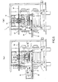
- FIGS. 4 and 5 are detail views showing the rolling mill 1 along with the welder 10, thickness gauge 20, and cutter 6 disposed at positions adjacent thereto (on the delivery side).
- FIG. 4, (a) shows a state where the welding guns 11 and so forth of the welder 10 are separated and retracted upward from the product strip A, while the thickness gauge 20 is set closer to the product strip A and is used to measure the thickness thereof.
- FIG. 4, (b) shows a state where the thickness gauge 20 is retracted sideward from the product strip A, while the welding guns 11 and so forth are set closer to the product strip A.
- FIG. 5, (a) shows a portion taken along a line Va-Va in FIG. 4, (a)
- FIG. 5, (b) shows a portion taken along a line Vb-Vb in FIG. 4, (b) .
- the welder 10 is formed of a spot-welder configured to perform series welding.
- the welding guns 11 each including an electrode provided with a pressing device and a electric feeder member for the same are disposed along with transformers (electrical transformers) 12 and an elevator (retraction cylinder) 13 for the welding guns 11.
- the welding guns 11 are configured to plunge the electrode by driving an air cylinder. Twelve welding guns 11 of this type are arrayed to form two rows in the rolling direction and six rows in the width direction and are connected to six transformers 12, so as to apply welding in two rows in the rolling direction by series welding.
- the welding guns 11 (specifically the driving electromagnetic valves thereof) and transformers 12 are structured such that machine parts and electric parts are contained in respective casings that are purged with air to protect the parts from water drops and vapor generated from a rolling coolant.
- the welding guns 11 and transformers 12 can be moved up and down by the elevator 13 between a retracted position shown in FIG. 4, (a) , separated upward from the line of the product strip A and an operating position shown in FIG. 4, (b) .
- the entire structure including the welding guns 11 and elevator 13 can be shifted sideward (toward the driving side of the rolling line) by a shifting mechanism including a shift cylinder 26 and a guide member 27 shown in FIG. 5 .
- a shifting mechanism including a shift cylinder 26 and a guide member 27 shown in FIG. 5 .
- a back bar 16 indispensable for series welding which is made of highly conductive chromium-copper, is fixedly disposed immediately below the pass line. Since liquid, such as the rolling coolant, flows down under the pass line, the components of the welder 10 are arranged such that only the back bar 16 is present below the pass line and the other components are present above the pass line.
- the welding guns 11 arrayed in six rows as described above are first used to apply spot-welding (series welding) on six places (twelve points) at one time, and then they are shifted sideward by several tens of millimeters (in the width direction) by the shift cylinder and used to apply welding on other six places (twelve points).
- spot-welding series welding
- the shift cylinder uses the shift cylinder to shift welding on other six places (twelve points).
- the thickness gauge 20 is formed of an X-ray thickness gauge (or it may be ⁇ -ray or ⁇ -ray thickness gauge), and includes an emitter 20a and a receiver 20b respectively attached to the upper and lower portions of a C-shaped frame, as shown in FIG. 5, (a) .
- the emitter 20a and receiver 20b are configured to sandwich the product strip A and measure the thickness of the product strip A by use of X-rays.
- the thickness gauge 20 can be moved by wheels 21 attached to the frame and rails 22 extending sideward (toward the driving side of the rolling line), between an operating position ( FIG. 5, (a) ) to sandwich the product strip A and measure the thickness thereof and a retracted position ( FIG. 5, (b) ) shifted sideward therefrom.
- the operating position of the thickness gauge 20 to measure the thickness overlaps with the operating position of the welding guns 11 moved down to apply welding on the product strip A (the positions of their center lines in the rolling direction align with each other).
- the thickness gauge 20 measures the thickness of the product strip A while the product strip A is being fed and subjected to rolling.
- the welding guns 11 apply welding on the product strip A when the feed of the product strip A is stopped. Accordingly, they perform measurement and welding infallibly with different timings at their operating positions described above. When they are not used for measurement or welding, they are moved to their retracted positions described above, which are separated from the product strip A.
- the welding guns 11 In a state where the welding guns 11 have been moved up to the retracted position or have been shifted sideward, they can be subjected to maintenance operations, such as replacement of the electrodes. In a state where the thickness gauge 20 has been retracted sideward, it can be subjected to calibration operations (such as zero point adjustment).
- a strip holding member 30 for pressing the product strip A in welding is disposed immediately above the pass line that is in contact with the upper surface of the back bar 16.
- the strip holding member 30 is formed of a flat plate with the front and rear end portions slightly inclined upward and can be moved by elevating cylinders 31.
- the strip holding member 30 is set at the upper position and serves to protect the thickness gauge 20.
- the strip holding member 30 has a hole 30a and holes 30b formed therein wherein the hole 30a allows X-rays of the thickness gauge 20 to pass through and the holes 30b allow the electrodes of the welding guns 11 to pass through.
- the back bar 16 formed of a flat plate fixed below the pass line has a hole at the center to allow X-rays of the thickness gauge 20 to pass through.
- FIG. 6 other elevating cylinders 35 and 36 are respectively disposed on the front and rear sides of the strip holding member 30. These cylinders are used to move up one of the end portions of the product strip A and leader strip L to prevent them from bumping into each other when the end portions are overlapped before they are connected by welding.
- reference symbols 6a and 6b respectively denote the upper blade and lower blade of the cutter 6.
- a reference symbol 9 denotes a pressing roll for the product strip A.
- FIG. 8 is a perspective view showing the structure and positional relationship of the welder 10, thickness gauge 20, and so forth described above, viewed from the driving side of the rolling line or the delivery side of the rolling mill 1. As shown in FIG. 8 , the welder 10 and thickness gauge 20 are arranged compact to minimize the occupancy space in the rolling line direction.
- FIG. 9 is a view for explaining the effect of reducing the part unprocessed, according to the present invention.
- the left part shows an off-gauge rate obtained by the ordinary metal rolling using no leader strip (the conventional rolling performed without a leader strip will be referred to as "ordinary metal rolling").
- the central part shows an off-gauge rate (on the lower side) and an improvement effect (on the upper side), both obtained by solely using a strip press.
- the right part shows an off-gauge rate (on the lower side) and an improvement effect (on the upper side), both obtained by use the system and method described above.
- Table 2 shows measurement results concerning the process time (excluding the rolling time) per unit coil of the product strip A.
- the metal rolling method described above As shown in Table 2, according to the metal rolling method described above, it is not necessary to wait for a rolled coil to be taken off the line, and it is not necessary to feed the next product strip A and wind it around the delivery side winder 4 by several turns. Consequently, as compared with the ordinary metal rolling performed without a leader strip, the metal rolling method described above shortens the process time (excluding the rolling time) per unit coil, even if it takes time to perform spot-welding. Further, since a small coil (Pup coil) formed of part unprocessed by rolling is not generated, it is possible to save a labor conventionally required to take out such a small coil by strapping it with a band.
- FIGS. 10 and 11 show production capacity obtained where the rolling of a product strip A was finished by an even number of passes.
- FIG. 10 is a view showing the average gauge of product for respective strip widths in a steel plant by the amount of production per unit of time (T/H) where the ordinary metal rolling is finished by four passes, five passes, and six passes.
- T/H amount of production per unit of time
- FIG. 11 is a view comparing a case where the metal rolling method described above was given to rolling finished by four passes and six passes and a case where the ordinary metal rolling is performed by five passes.
- FIG. 11 where the method described above was applied the rolling using four passes rendered a further improvement in productivity, and even the rolling using six passes rendered an improvement in productivity due to a shorter process time per unit coil as compared with the ordinary metal rolling using five passes.
- a welder for a metal rolling system, a metal rolling system, and a metal rolling method according to the present invention are industrially applicable to rolling techniques performed while causing a product strip (strip to be rolled or the like) to pass back and forth.
- a product strip strip to be rolled or the like
Landscapes
- Engineering & Computer Science (AREA)
- Mechanical Engineering (AREA)
- Metal Rolling (AREA)
- Resistance Welding (AREA)
- Winding, Rewinding, Material Storage Devices (AREA)
Claims (5)
- Metall-Walzverfahren zum Walzen eines Erzeugnisbands (A) unter Verwendung einer Walzeinrichtung (1) und einer Wickeleinrichtung (3, 4), die auf einer Eintrittsseite und einer Austrittsseite der Walzeinrichtung angeordnet ist, während diese das Erzeugnisband dazu bewegt, sich durch die Walzeinrichtung hin und her zu bewegen, wobei das Verfahren umfasst:Schweißen eines Führungsbandes (L), das durch die Wickeleinrichtung (4) auf der Austrittsseite gehalten wird, an einen Endabschnitt des Erzeugnisbands, und Aussetzen des Erzeugnisbands zu reversiblen Walzen durch die Walzeinrichtung, ohne das Führungsband und einen an das Führungsband angeschweißten Teil (Lc) des Erzeugnisbands zu walzen, während Spannung von der Wickeleinrichtung auf der Austrittsseite durch das Führungsband an das Erzeugnisband selbst in der Nähe des Endabschnitts davon angelegt wird; undSchneiden des Führungsbands an einer Position aus dem geschweißten Teil am Ende eines geraden Ordnungszahldurchlaufs in Richtung der Wickeleinrichtung (3) auf der Eintrittsseite, und Aufwickeln des Erzeugnisbands mit dem geschweißten Teil an dem Endabschnitt auf die Wickeleinrichtung auf der Eintrittsseite, ohne den geschweißten Teils auszuschneiden, gefolgt von Entnehmen einer so aufgewickelten Rolle des Erzeugnisbands.
- Metall-Walzverfahren nach Anspruch 1, wobei das Verfahren umfasst, Durchführen des Schweißen des Führungsbands an den Endabschnitt des Erzeugnisbands und des anschließenden Schneidens des Führungsbands mit einer Schweißeinrichtung (10) und einer Schneideinrichtung (6), die zwischen der Walzeinrichtung (1) und der Wickeleinrichtung auf Austrittsseite oder zwischen der Walzeinrichtung (1) und der Wickeleinrichtung auf der Eintrittsseite angeordnet sind.
- Metall-Walzverfahren nach Anspruch 1 oder 2, wobei, nach dem Schneiden des Führungsbands und dem Aufwickeln des Erzeugnisbands auf die Wickeleinrichtung auf der Eintrittsseite, und vor dem Schneiden des geschweißten Teils aus der Rolle des Erzeugnisbands, das Verfahren das Zuführen eines weiteren Erzeugnisbands von einer Abwickelrolle (2) auf der Eintrittsseite in Richtung der Austrittsseite umfasst.
- Metall-Walzverfahren nach einem der Ansprüche 1 bis 3, wobei, nach einzelnen sequentiellen Aussetzen einer Vielzahl von Erzeugnisbändern zu dem reversiblen Walzen und dem Entnehmen, während das gleiche Führungsband verwendet wird, und dann einmal das Führungsbands von der Wickeleinrichtung auf der Austrittsseite herausgenommen wird, das Verfahren umfasst:Halten eines Endabschnitts von einem Erzeugnisband direkt durch die Wickeleinrichtung auf der Austrittsseite, ohne ein Führungsband zu verwenden, und Aussetzen dieses einen Erzeugnisbands zu reversiblen Walzen durch die Walzeinrichtung, während Spannung von den Wickeleinrichtungen angelegt wird; undSchneiden dieses einen Erzeugnisbands, das durch die Wickelreinrichtung auf der Austrittseite gehalten wird, am Ende eines geraden Ordnungszahldurchlaufs in Richtung der Wickeleinrichtung auf der Eintrittsseite, wodurch von dem einen Erzeugnisband ein Führungsband erhalten wird, das für eine weitere Vielzahl von Erzeugnisbändern verwendet werden kann, die anschließend dem Walzen ausgesetzt werden.
- Metall-Walzverfahren nach einem der Ansprüche 1 bis 4, wobei das Verfahren umfasst, Ausführen des Schweißens durch eine Punkt-Schweißeinrichtung (10), die einen hinteren Balken (16) unterhalb der Durchgangslinie und Schweißpistolen (11) oberhalb der Durchgangslinie aufweist, um Serienschweißen auszuführen, um eine Vielzahl von Punkten zur gleichen Zeit zu schweißen.
Applications Claiming Priority (2)
| Application Number | Priority Date | Filing Date | Title |
|---|---|---|---|
| JP2007273253A JP5165335B2 (ja) | 2007-10-20 | 2007-10-20 | 圧延設備用溶接機、圧延設備および圧延方法 |
| EP08839073A EP2221120A4 (de) | 2007-10-20 | 2008-10-20 | Schweissmaschine für walzwerk, walzwerk und walzverfahren |
Related Parent Applications (1)
| Application Number | Title | Priority Date | Filing Date |
|---|---|---|---|
| EP08839073.7 Division | 2008-10-20 |
Publications (2)
| Publication Number | Publication Date |
|---|---|
| EP2425905A1 EP2425905A1 (de) | 2012-03-07 |
| EP2425905B1 true EP2425905B1 (de) | 2013-09-18 |
Family
ID=40567516
Family Applications (2)
| Application Number | Title | Priority Date | Filing Date |
|---|---|---|---|
| EP11191508.8A Not-in-force EP2425905B1 (de) | 2007-10-20 | 2008-10-20 | Metallrollverfahren |
| EP08839073A Withdrawn EP2221120A4 (de) | 2007-10-20 | 2008-10-20 | Schweissmaschine für walzwerk, walzwerk und walzverfahren |
Family Applications After (1)
| Application Number | Title | Priority Date | Filing Date |
|---|---|---|---|
| EP08839073A Withdrawn EP2221120A4 (de) | 2007-10-20 | 2008-10-20 | Schweissmaschine für walzwerk, walzwerk und walzverfahren |
Country Status (7)
| Country | Link |
|---|---|
| US (1) | US8424353B2 (de) |
| EP (2) | EP2425905B1 (de) |
| JP (1) | JP5165335B2 (de) |
| KR (1) | KR101203212B1 (de) |
| CN (1) | CN101835546B (de) |
| ES (1) | ES2437136T3 (de) |
| WO (1) | WO2009051257A1 (de) |
Families Citing this family (14)
| Publication number | Priority date | Publication date | Assignee | Title |
|---|---|---|---|---|
| JP5572046B2 (ja) * | 2010-09-13 | 2014-08-13 | 株式会社神戸製鋼所 | 異材接合方法 |
| CN103379969B (zh) * | 2011-03-18 | 2015-06-10 | 株式会社日立制作所 | 轧制控制装置及轧制控制方法 |
| CN102632388B (zh) * | 2012-04-28 | 2015-10-28 | 宝山钢铁股份有限公司 | 一种适用于单机架轧机的引带焊接生产线及方法 |
| JP5765328B2 (ja) * | 2012-12-26 | 2015-08-19 | Jfeスチール株式会社 | 冷間圧延設備及び冷間圧延方法 |
| JP6076234B2 (ja) * | 2013-11-01 | 2017-02-08 | Jfeプラントエンジ株式会社 | 鋼板コイルの冷間圧延方法およびその冷間圧延設備 |
| CN103736743A (zh) * | 2013-12-25 | 2014-04-23 | 烨辉(中国)科技材料有限公司 | 一种具有头尾卷焊接功能的单机架冷轧机 |
| CN105710128A (zh) * | 2016-04-01 | 2016-06-29 | 唐山钢铁集团有限责任公司 | 一种提高往复轧制板材成材率的方法 |
| CN106391724B (zh) * | 2016-11-08 | 2019-02-05 | 广西梧州市金海不锈钢有限公司 | 一种自动可逆冷轧轧制力控制装置及控制方法 |
| DE102017117145A1 (de) * | 2017-07-28 | 2019-01-31 | Hauni Maschinenbau Gmbh | Vorrichtung zum Verbinden von Materialbahnen |
| JP7042190B2 (ja) * | 2018-08-08 | 2022-03-25 | スチールプランテック株式会社 | リール装置、並びにそれを備えた圧延設備及び圧延方法 |
| EP3883701B1 (de) | 2018-11-23 | 2022-10-19 | John Cockerill S.A. | Flexible kaltwalzanlage und verfahren zur umwandlung davon |
| CN111687239A (zh) * | 2020-06-22 | 2020-09-22 | 成都亨通光通信有限公司 | 一种光缆生产用钢带分切与长盘收卷生产线及方法 |
| CN114618882B (zh) * | 2022-03-25 | 2025-02-18 | 中冶南方工程技术有限公司 | 一种冷轧带钢生产机组及生产工艺 |
| CN116689484A (zh) * | 2023-06-02 | 2023-09-05 | 首钢智新迁安电磁材料有限公司 | 一种用于可逆冷轧机的带钢轧制方法及装置 |
Family Cites Families (10)
| Publication number | Priority date | Publication date | Assignee | Title |
|---|---|---|---|---|
| US1844889A (en) * | 1926-12-31 | 1932-02-09 | Barrett Co | Distillation of tar, etc. |
| JPS63220902A (ja) * | 1987-03-10 | 1988-09-14 | Nkk Corp | 高珪素鋼板の温間圧延方法 |
| JP2721716B2 (ja) * | 1989-10-25 | 1998-03-04 | 株式会社日立製作所 | 可逆式冷間圧延方法および設備 |
| JPH0623559A (ja) * | 1992-06-24 | 1994-02-01 | Kawasaki Steel Corp | 金属ストリップの接続方法 |
| JP2771101B2 (ja) * | 1993-10-29 | 1998-07-02 | 川崎製鉄株式会社 | 鋼ストリップのスポット溶接による接続方法 |
| JPH11342402A (ja) * | 1998-05-29 | 1999-12-14 | Kawasaki Steel Corp | 冷間圧延設備 |
| CA2790773C (en) * | 2003-11-15 | 2015-06-30 | Tec-Option, Inc. | Modular welding equipment |
| JP4508949B2 (ja) * | 2005-06-03 | 2010-07-21 | スチールプランテック株式会社 | 圧延方法および圧延設備 |
| EP1844889B1 (de) | 2006-04-13 | 2019-07-17 | KUKA Deutschland GmbH | Verfahren und Vorrichtung zum punktförmigen Schweissen an mindestens einem Werkstück positionierter Schweisselektroden mittels mindestens eines Roboters |
| US10717032B2 (en) * | 2006-09-21 | 2020-07-21 | Acs Industries, Inc. | Expanded metal filters |
-
2007
- 2007-10-20 JP JP2007273253A patent/JP5165335B2/ja active Active
-
2008
- 2008-10-20 EP EP11191508.8A patent/EP2425905B1/de not_active Not-in-force
- 2008-10-20 WO PCT/JP2008/068980 patent/WO2009051257A1/ja not_active Ceased
- 2008-10-20 CN CN2008801123552A patent/CN101835546B/zh active Active
- 2008-10-20 KR KR1020107010791A patent/KR101203212B1/ko active Active
- 2008-10-20 EP EP08839073A patent/EP2221120A4/de not_active Withdrawn
- 2008-10-20 US US12/738,892 patent/US8424353B2/en not_active Expired - Fee Related
- 2008-10-20 ES ES11191508.8T patent/ES2437136T3/es active Active
Also Published As
| Publication number | Publication date |
|---|---|
| US20100218579A1 (en) | 2010-09-02 |
| EP2221120A4 (de) | 2011-07-13 |
| CN101835546A (zh) | 2010-09-15 |
| EP2221120A1 (de) | 2010-08-25 |
| CN101835546B (zh) | 2013-07-31 |
| EP2425905A1 (de) | 2012-03-07 |
| ES2437136T3 (es) | 2014-01-09 |
| KR20100072355A (ko) | 2010-06-30 |
| US8424353B2 (en) | 2013-04-23 |
| JP5165335B2 (ja) | 2013-03-21 |
| WO2009051257A1 (ja) | 2009-04-23 |
| KR101203212B1 (ko) | 2012-11-20 |
| JP2009101367A (ja) | 2009-05-14 |
Similar Documents
| Publication | Publication Date | Title |
|---|---|---|
| US8424353B2 (en) | Welder for metal rolling system, metal rolling system, and metal rolling method | |
| EP0661112B1 (de) | Verfahren und vorrichtung zum kontinuierlichen warmwalzen von metallischem walzgut | |
| US4976024A (en) | Method of and apparatus for rolling directly coupled with continuous casting | |
| US5190204A (en) | Laser butt-welding device and method | |
| US2078365A (en) | Means and method for making strip | |
| JP2528808B2 (ja) | 鋼片の連続熱間圧延方法 | |
| RU2563394C2 (ru) | Линия по производству прямошовных сварных труб большого диаметра | |
| EP3954478B1 (de) | Vorrichtung zur herstellung eines separators für eine brennstoffzelle und verfahren zur herstellung davon | |
| CN114535359A (zh) | 薄带铸轧高强钢平整生产线及平整工艺 | |
| JPH0839276A (ja) | 連続した金属シートを形成するための2つの金属シートコイルをレーザビームによって突き合せ接合及び溶接する装置 | |
| US3700157A (en) | Apparatus for feeding strip-like material to a processing apparatus | |
| CN111774422B (zh) | 降低连轧机停车损失的方法 | |
| CN102059490A (zh) | 卷钢尾板接头点焊设备 | |
| EP2812133B1 (de) | Einlaufabschnitt für eine beizlinie, für eine kontinuierliche tandemwalzstrasse oder für eine beizlinie, die mit einer tandemwalzstrasse gekoppelt ist | |
| EP3208005B1 (de) | Kombinierte schweiss- und walzanlage für metallbänder | |
| WO2019068388A1 (de) | Multiflexible walzanlage | |
| CN114682651A (zh) | 薄带铸轧高强钢拉矫生产线及拉矫工艺 | |
| KR101726089B1 (ko) | 연속공정의 분리연결장치 및, 이를 이용한 연속공정의 가동방법 | |
| CN208391329U (zh) | 冷轧硬卷卷芯焊接装置 | |
| CN108284327B (zh) | 复合卷撕分精整重卷设备及方法 | |
| CN210877811U (zh) | 带钢防松紧分坑装置 | |
| JP2015085371A (ja) | 鋼板コイルの冷間圧延方法およびその冷間圧延設備 | |
| KR100742889B1 (ko) | 열연코일 오작재 처리장치 | |
| JPH07164008A (ja) | 酸洗−冷間圧延設備 | |
| JPH0824926A (ja) | 金属帯の製造方法 |
Legal Events
| Date | Code | Title | Description |
|---|---|---|---|
| AC | Divisional application: reference to earlier application |
Ref document number: 2221120 Country of ref document: EP Kind code of ref document: P |
|
| AK | Designated contracting states |
Kind code of ref document: A1 Designated state(s): AT BE BG CH CY CZ DE DK EE ES FI FR GB GR HR HU IE IS IT LI LT LU LV MC MT NL NO PL PT RO SE SI SK TR |
|
| PUAI | Public reference made under article 153(3) epc to a published international application that has entered the european phase |
Free format text: ORIGINAL CODE: 0009012 |
|
| 17P | Request for examination filed |
Effective date: 20120720 |
|
| RIC1 | Information provided on ipc code assigned before grant |
Ipc: B21B 15/00 20060101AFI20130222BHEP Ipc: B23K 101/16 20060101ALI20130222BHEP Ipc: B21C 47/26 20060101ALI20130222BHEP Ipc: B21B 1/32 20060101ALI20130222BHEP Ipc: B23K 11/11 20060101ALI20130222BHEP |
|
| GRAP | Despatch of communication of intention to grant a patent |
Free format text: ORIGINAL CODE: EPIDOSNIGR1 |
|
| INTG | Intention to grant announced |
Effective date: 20130408 |
|
| GRAS | Grant fee paid |
Free format text: ORIGINAL CODE: EPIDOSNIGR3 |
|
| GRAA | (expected) grant |
Free format text: ORIGINAL CODE: 0009210 |
|
| AC | Divisional application: reference to earlier application |
Ref document number: 2221120 Country of ref document: EP Kind code of ref document: P |
|
| AK | Designated contracting states |
Kind code of ref document: B1 Designated state(s): AT BE BG CH CY CZ DE DK EE ES FI FR GB GR HR HU IE IS IT LI LT LU LV MC MT NL NO PL PT RO SE SI SK TR |
|
| REG | Reference to a national code |
Ref country code: GB Ref legal event code: FG4D |
|
| REG | Reference to a national code |
Ref country code: CH Ref legal event code: EP |
|
| REG | Reference to a national code |
Ref country code: IE Ref legal event code: FG4D |
|
| REG | Reference to a national code |
Ref country code: AT Ref legal event code: REF Ref document number: 632452 Country of ref document: AT Kind code of ref document: T Effective date: 20131015 |
|
| REG | Reference to a national code |
Ref country code: DE Ref legal event code: R096 Ref document number: 602008027728 Country of ref document: DE Effective date: 20131114 |
|
| REG | Reference to a national code |
Ref country code: ES Ref legal event code: FG2A Ref document number: 2437136 Country of ref document: ES Kind code of ref document: T3 Effective date: 20140109 |
|
| PG25 | Lapsed in a contracting state [announced via postgrant information from national office to epo] |
Ref country code: SE Free format text: LAPSE BECAUSE OF FAILURE TO SUBMIT A TRANSLATION OF THE DESCRIPTION OR TO PAY THE FEE WITHIN THE PRESCRIBED TIME-LIMIT Effective date: 20130918 Ref country code: CY Free format text: LAPSE BECAUSE OF FAILURE TO SUBMIT A TRANSLATION OF THE DESCRIPTION OR TO PAY THE FEE WITHIN THE PRESCRIBED TIME-LIMIT Effective date: 20130814 Ref country code: HR Free format text: LAPSE BECAUSE OF FAILURE TO SUBMIT A TRANSLATION OF THE DESCRIPTION OR TO PAY THE FEE WITHIN THE PRESCRIBED TIME-LIMIT Effective date: 20130918 Ref country code: NO Free format text: LAPSE BECAUSE OF FAILURE TO SUBMIT A TRANSLATION OF THE DESCRIPTION OR TO PAY THE FEE WITHIN THE PRESCRIBED TIME-LIMIT Effective date: 20131218 Ref country code: LT Free format text: LAPSE BECAUSE OF FAILURE TO SUBMIT A TRANSLATION OF THE DESCRIPTION OR TO PAY THE FEE WITHIN THE PRESCRIBED TIME-LIMIT Effective date: 20130918 |
|
| REG | Reference to a national code |
Ref country code: NL Ref legal event code: VDEP Effective date: 20130918 |
|
| REG | Reference to a national code |
Ref country code: AT Ref legal event code: MK05 Ref document number: 632452 Country of ref document: AT Kind code of ref document: T Effective date: 20130918 |
|
| REG | Reference to a national code |
Ref country code: LT Ref legal event code: MG4D |
|
| PG25 | Lapsed in a contracting state [announced via postgrant information from national office to epo] |
Ref country code: SI Free format text: LAPSE BECAUSE OF FAILURE TO SUBMIT A TRANSLATION OF THE DESCRIPTION OR TO PAY THE FEE WITHIN THE PRESCRIBED TIME-LIMIT Effective date: 20130918 Ref country code: GR Free format text: LAPSE BECAUSE OF FAILURE TO SUBMIT A TRANSLATION OF THE DESCRIPTION OR TO PAY THE FEE WITHIN THE PRESCRIBED TIME-LIMIT Effective date: 20131219 Ref country code: FI Free format text: LAPSE BECAUSE OF FAILURE TO SUBMIT A TRANSLATION OF THE DESCRIPTION OR TO PAY THE FEE WITHIN THE PRESCRIBED TIME-LIMIT Effective date: 20130918 Ref country code: LV Free format text: LAPSE BECAUSE OF FAILURE TO SUBMIT A TRANSLATION OF THE DESCRIPTION OR TO PAY THE FEE WITHIN THE PRESCRIBED TIME-LIMIT Effective date: 20130918 |
|
| PG25 | Lapsed in a contracting state [announced via postgrant information from national office to epo] |
Ref country code: BE Free format text: LAPSE BECAUSE OF FAILURE TO SUBMIT A TRANSLATION OF THE DESCRIPTION OR TO PAY THE FEE WITHIN THE PRESCRIBED TIME-LIMIT Effective date: 20130918 Ref country code: CY Free format text: LAPSE BECAUSE OF FAILURE TO SUBMIT A TRANSLATION OF THE DESCRIPTION OR TO PAY THE FEE WITHIN THE PRESCRIBED TIME-LIMIT Effective date: 20130918 |
|
| PG25 | Lapsed in a contracting state [announced via postgrant information from national office to epo] |
Ref country code: EE Free format text: LAPSE BECAUSE OF FAILURE TO SUBMIT A TRANSLATION OF THE DESCRIPTION OR TO PAY THE FEE WITHIN THE PRESCRIBED TIME-LIMIT Effective date: 20130918 Ref country code: SK Free format text: LAPSE BECAUSE OF FAILURE TO SUBMIT A TRANSLATION OF THE DESCRIPTION OR TO PAY THE FEE WITHIN THE PRESCRIBED TIME-LIMIT Effective date: 20130918 Ref country code: IS Free format text: LAPSE BECAUSE OF FAILURE TO SUBMIT A TRANSLATION OF THE DESCRIPTION OR TO PAY THE FEE WITHIN THE PRESCRIBED TIME-LIMIT Effective date: 20140118 Ref country code: CZ Free format text: LAPSE BECAUSE OF FAILURE TO SUBMIT A TRANSLATION OF THE DESCRIPTION OR TO PAY THE FEE WITHIN THE PRESCRIBED TIME-LIMIT Effective date: 20130918 Ref country code: NL Free format text: LAPSE BECAUSE OF FAILURE TO SUBMIT A TRANSLATION OF THE DESCRIPTION OR TO PAY THE FEE WITHIN THE PRESCRIBED TIME-LIMIT Effective date: 20130918 |
|
| PG25 | Lapsed in a contracting state [announced via postgrant information from national office to epo] |
Ref country code: PL Free format text: LAPSE BECAUSE OF FAILURE TO SUBMIT A TRANSLATION OF THE DESCRIPTION OR TO PAY THE FEE WITHIN THE PRESCRIBED TIME-LIMIT Effective date: 20130918 Ref country code: AT Free format text: LAPSE BECAUSE OF FAILURE TO SUBMIT A TRANSLATION OF THE DESCRIPTION OR TO PAY THE FEE WITHIN THE PRESCRIBED TIME-LIMIT Effective date: 20130918 |
|
| REG | Reference to a national code |
Ref country code: CH Ref legal event code: PL |
|
| REG | Reference to a national code |
Ref country code: DE Ref legal event code: R097 Ref document number: 602008027728 Country of ref document: DE |
|
| PG25 | Lapsed in a contracting state [announced via postgrant information from national office to epo] |
Ref country code: PT Free format text: LAPSE BECAUSE OF FAILURE TO SUBMIT A TRANSLATION OF THE DESCRIPTION OR TO PAY THE FEE WITHIN THE PRESCRIBED TIME-LIMIT Effective date: 20140120 Ref country code: MC Free format text: LAPSE BECAUSE OF FAILURE TO SUBMIT A TRANSLATION OF THE DESCRIPTION OR TO PAY THE FEE WITHIN THE PRESCRIBED TIME-LIMIT Effective date: 20130918 |
|
| PLBE | No opposition filed within time limit |
Free format text: ORIGINAL CODE: 0009261 |
|
| STAA | Information on the status of an ep patent application or granted ep patent |
Free format text: STATUS: NO OPPOSITION FILED WITHIN TIME LIMIT |
|
| REG | Reference to a national code |
Ref country code: IE Ref legal event code: MM4A |
|
| PG25 | Lapsed in a contracting state [announced via postgrant information from national office to epo] |
Ref country code: CH Free format text: LAPSE BECAUSE OF NON-PAYMENT OF DUE FEES Effective date: 20131031 Ref country code: LI Free format text: LAPSE BECAUSE OF NON-PAYMENT OF DUE FEES Effective date: 20131031 |
|
| 26N | No opposition filed |
Effective date: 20140619 |
|
| REG | Reference to a national code |
Ref country code: DE Ref legal event code: R097 Ref document number: 602008027728 Country of ref document: DE Effective date: 20140619 |
|
| PG25 | Lapsed in a contracting state [announced via postgrant information from national office to epo] |
Ref country code: DK Free format text: LAPSE BECAUSE OF FAILURE TO SUBMIT A TRANSLATION OF THE DESCRIPTION OR TO PAY THE FEE WITHIN THE PRESCRIBED TIME-LIMIT Effective date: 20130918 |
|
| PG25 | Lapsed in a contracting state [announced via postgrant information from national office to epo] |
Ref country code: IE Free format text: LAPSE BECAUSE OF NON-PAYMENT OF DUE FEES Effective date: 20131020 |
|
| PG25 | Lapsed in a contracting state [announced via postgrant information from national office to epo] |
Ref country code: RO Free format text: LAPSE BECAUSE OF FAILURE TO SUBMIT A TRANSLATION OF THE DESCRIPTION OR TO PAY THE FEE WITHIN THE PRESCRIBED TIME-LIMIT Effective date: 20130918 |
|
| PG25 | Lapsed in a contracting state [announced via postgrant information from national office to epo] |
Ref country code: TR Free format text: LAPSE BECAUSE OF FAILURE TO SUBMIT A TRANSLATION OF THE DESCRIPTION OR TO PAY THE FEE WITHIN THE PRESCRIBED TIME-LIMIT Effective date: 20130918 |
|
| PG25 | Lapsed in a contracting state [announced via postgrant information from national office to epo] |
Ref country code: HU Free format text: LAPSE BECAUSE OF FAILURE TO SUBMIT A TRANSLATION OF THE DESCRIPTION OR TO PAY THE FEE WITHIN THE PRESCRIBED TIME-LIMIT; INVALID AB INITIO Effective date: 20081020 Ref country code: BG Free format text: LAPSE BECAUSE OF FAILURE TO SUBMIT A TRANSLATION OF THE DESCRIPTION OR TO PAY THE FEE WITHIN THE PRESCRIBED TIME-LIMIT Effective date: 20130918 Ref country code: LU Free format text: LAPSE BECAUSE OF NON-PAYMENT OF DUE FEES Effective date: 20131020 |
|
| PG25 | Lapsed in a contracting state [announced via postgrant information from national office to epo] |
Ref country code: MT Free format text: LAPSE BECAUSE OF FAILURE TO SUBMIT A TRANSLATION OF THE DESCRIPTION OR TO PAY THE FEE WITHIN THE PRESCRIBED TIME-LIMIT Effective date: 20130918 |
|
| REG | Reference to a national code |
Ref country code: FR Ref legal event code: PLFP Year of fee payment: 8 |
|
| REG | Reference to a national code |
Ref country code: FR Ref legal event code: PLFP Year of fee payment: 9 |
|
| REG | Reference to a national code |
Ref country code: FR Ref legal event code: PLFP Year of fee payment: 10 |
|
| REG | Reference to a national code |
Ref country code: FR Ref legal event code: PLFP Year of fee payment: 11 |
|
| PGFP | Annual fee paid to national office [announced via postgrant information from national office to epo] |
Ref country code: IT Payment date: 20230913 Year of fee payment: 16 Ref country code: GB Payment date: 20230831 Year of fee payment: 16 |
|
| PGFP | Annual fee paid to national office [announced via postgrant information from national office to epo] |
Ref country code: FR Payment date: 20230911 Year of fee payment: 16 |
|
| PGFP | Annual fee paid to national office [announced via postgrant information from national office to epo] |
Ref country code: ES Payment date: 20231102 Year of fee payment: 16 |
|
| PGFP | Annual fee paid to national office [announced via postgrant information from national office to epo] |
Ref country code: DE Payment date: 20230830 Year of fee payment: 16 |
|
| REG | Reference to a national code |
Ref country code: DE Ref legal event code: R119 Ref document number: 602008027728 Country of ref document: DE |
|
| GBPC | Gb: european patent ceased through non-payment of renewal fee |
Effective date: 20241020 |
|
| PG25 | Lapsed in a contracting state [announced via postgrant information from national office to epo] |
Ref country code: DE Free format text: LAPSE BECAUSE OF NON-PAYMENT OF DUE FEES Effective date: 20250501 |
|
| PG25 | Lapsed in a contracting state [announced via postgrant information from national office to epo] |
Ref country code: GB Free format text: LAPSE BECAUSE OF NON-PAYMENT OF DUE FEES Effective date: 20241020 |
|
| PG25 | Lapsed in a contracting state [announced via postgrant information from national office to epo] |
Ref country code: FR Free format text: LAPSE BECAUSE OF NON-PAYMENT OF DUE FEES Effective date: 20241031 |
|
| PG25 | Lapsed in a contracting state [announced via postgrant information from national office to epo] |
Ref country code: IT Free format text: LAPSE BECAUSE OF NON-PAYMENT OF DUE FEES Effective date: 20241020 |
|
| REG | Reference to a national code |
Ref country code: ES Ref legal event code: FD2A Effective date: 20251201 |
|
| PG25 | Lapsed in a contracting state [announced via postgrant information from national office to epo] |
Ref country code: ES Free format text: LAPSE BECAUSE OF NON-PAYMENT OF DUE FEES Effective date: 20241021 |