EP2425888A1 - Wabenstrukturkörper - Google Patents
Wabenstrukturkörper Download PDFInfo
- Publication number
- EP2425888A1 EP2425888A1 EP11177064A EP11177064A EP2425888A1 EP 2425888 A1 EP2425888 A1 EP 2425888A1 EP 11177064 A EP11177064 A EP 11177064A EP 11177064 A EP11177064 A EP 11177064A EP 2425888 A1 EP2425888 A1 EP 2425888A1
- Authority
- EP
- European Patent Office
- Prior art keywords
- honeycomb structural
- structural body
- pore
- distribution
- pore diameter
- Prior art date
- Legal status (The legal status is an assumption and is not a legal conclusion. Google has not performed a legal analysis and makes no representation as to the accuracy of the status listed.)
- Granted
Links
Images


Classifications
-
- F—MECHANICAL ENGINEERING; LIGHTING; HEATING; WEAPONS; BLASTING
- F01—MACHINES OR ENGINES IN GENERAL; ENGINE PLANTS IN GENERAL; STEAM ENGINES
- F01N—GAS-FLOW SILENCERS OR EXHAUST APPARATUS FOR MACHINES OR ENGINES IN GENERAL; GAS-FLOW SILENCERS OR EXHAUST APPARATUS FOR INTERNAL-COMBUSTION ENGINES
- F01N3/00—Exhaust or silencing apparatus having means for purifying, rendering innocuous, or otherwise treating exhaust
- F01N3/08—Exhaust or silencing apparatus having means for purifying, rendering innocuous, or otherwise treating exhaust for rendering innocuous
- F01N3/10—Exhaust or silencing apparatus having means for purifying, rendering innocuous, or otherwise treating exhaust for rendering innocuous by thermal or catalytic conversion of noxious components of exhaust
- F01N3/24—Exhaust or silencing apparatus having means for purifying, rendering innocuous, or otherwise treating exhaust for rendering innocuous by thermal or catalytic conversion of noxious components of exhaust characterised by constructional aspects of converting apparatus
- F01N3/28—Construction of catalytic reactors
- F01N3/2803—Construction of catalytic reactors characterised by structure, by material or by manufacturing of catalyst support
- F01N3/2825—Ceramics
- F01N3/2828—Ceramic multi-channel monoliths, e.g. honeycombs
-
- B—PERFORMING OPERATIONS; TRANSPORTING
- B01—PHYSICAL OR CHEMICAL PROCESSES OR APPARATUS IN GENERAL
- B01D—SEPARATION
- B01D46/00—Filters or filtering processes specially modified for separating dispersed particles from gases or vapours
- B01D46/24—Particle separators, e.g. dust precipitators, using rigid hollow filter bodies
- B01D46/2403—Particle separators, e.g. dust precipitators, using rigid hollow filter bodies characterised by the physical shape or structure of the filtering element
- B01D46/2418—Honeycomb filters
- B01D46/2425—Honeycomb filters characterized by parameters related to the physical properties of the honeycomb structure material
- B01D46/2429—Honeycomb filters characterized by parameters related to the physical properties of the honeycomb structure material of the honeycomb walls or cells
-
- B—PERFORMING OPERATIONS; TRANSPORTING
- B01—PHYSICAL OR CHEMICAL PROCESSES OR APPARATUS IN GENERAL
- B01D—SEPARATION
- B01D46/00—Filters or filtering processes specially modified for separating dispersed particles from gases or vapours
- B01D46/24—Particle separators, e.g. dust precipitators, using rigid hollow filter bodies
- B01D46/2403—Particle separators, e.g. dust precipitators, using rigid hollow filter bodies characterised by the physical shape or structure of the filtering element
- B01D46/2418—Honeycomb filters
- B01D46/2425—Honeycomb filters characterized by parameters related to the physical properties of the honeycomb structure material
- B01D46/24491—Porosity
-
- B—PERFORMING OPERATIONS; TRANSPORTING
- B01—PHYSICAL OR CHEMICAL PROCESSES OR APPARATUS IN GENERAL
- B01D—SEPARATION
- B01D46/00—Filters or filtering processes specially modified for separating dispersed particles from gases or vapours
- B01D46/24—Particle separators, e.g. dust precipitators, using rigid hollow filter bodies
- B01D46/2403—Particle separators, e.g. dust precipitators, using rigid hollow filter bodies characterised by the physical shape or structure of the filtering element
- B01D46/2418—Honeycomb filters
- B01D46/2451—Honeycomb filters characterized by the geometrical structure, shape, pattern or configuration or parameters related to the geometry of the structure
- B01D46/2455—Honeycomb filters characterized by the geometrical structure, shape, pattern or configuration or parameters related to the geometry of the structure of the whole honeycomb or segments
-
- B—PERFORMING OPERATIONS; TRANSPORTING
- B01—PHYSICAL OR CHEMICAL PROCESSES OR APPARATUS IN GENERAL
- B01D—SEPARATION
- B01D46/00—Filters or filtering processes specially modified for separating dispersed particles from gases or vapours
- B01D46/24—Particle separators, e.g. dust precipitators, using rigid hollow filter bodies
- B01D46/2403—Particle separators, e.g. dust precipitators, using rigid hollow filter bodies characterised by the physical shape or structure of the filtering element
- B01D46/2418—Honeycomb filters
- B01D46/2451—Honeycomb filters characterized by the geometrical structure, shape, pattern or configuration or parameters related to the geometry of the structure
- B01D46/2474—Honeycomb filters characterized by the geometrical structure, shape, pattern or configuration or parameters related to the geometry of the structure of the walls along the length of the honeycomb
-
- B—PERFORMING OPERATIONS; TRANSPORTING
- B01—PHYSICAL OR CHEMICAL PROCESSES OR APPARATUS IN GENERAL
- B01D—SEPARATION
- B01D46/00—Filters or filtering processes specially modified for separating dispersed particles from gases or vapours
- B01D46/24—Particle separators, e.g. dust precipitators, using rigid hollow filter bodies
- B01D46/2403—Particle separators, e.g. dust precipitators, using rigid hollow filter bodies characterised by the physical shape or structure of the filtering element
- B01D46/2418—Honeycomb filters
- B01D46/2451—Honeycomb filters characterized by the geometrical structure, shape, pattern or configuration or parameters related to the geometry of the structure
- B01D46/2482—Thickness, height, width, length or diameter
-
- B—PERFORMING OPERATIONS; TRANSPORTING
- B01—PHYSICAL OR CHEMICAL PROCESSES OR APPARATUS IN GENERAL
- B01D—SEPARATION
- B01D46/00—Filters or filtering processes specially modified for separating dispersed particles from gases or vapours
- B01D46/24—Particle separators, e.g. dust precipitators, using rigid hollow filter bodies
- B01D46/2403—Particle separators, e.g. dust precipitators, using rigid hollow filter bodies characterised by the physical shape or structure of the filtering element
- B01D46/2418—Honeycomb filters
- B01D46/2451—Honeycomb filters characterized by the geometrical structure, shape, pattern or configuration or parameters related to the geometry of the structure
- B01D46/2484—Cell density, area or aspect ratio
-
- C—CHEMISTRY; METALLURGY
- C04—CEMENTS; CONCRETE; ARTIFICIAL STONE; CERAMICS; REFRACTORIES
- C04B—LIME, MAGNESIA; SLAG; CEMENTS; COMPOSITIONS THEREOF, e.g. MORTARS, CONCRETE OR LIKE BUILDING MATERIALS; ARTIFICIAL STONE; CERAMICS; REFRACTORIES; TREATMENT OF NATURAL STONE
- C04B38/00—Porous mortars, concrete, artificial stone or ceramic ware; Preparation thereof
- C04B38/0006—Honeycomb structures
- C04B38/0009—Honeycomb structures characterised by features relating to the cell walls, e.g. wall thickness or distribution of pores in the walls
-
- C—CHEMISTRY; METALLURGY
- C04—CEMENTS; CONCRETE; ARTIFICIAL STONE; CERAMICS; REFRACTORIES
- C04B—LIME, MAGNESIA; SLAG; CEMENTS; COMPOSITIONS THEREOF, e.g. MORTARS, CONCRETE OR LIKE BUILDING MATERIALS; ARTIFICIAL STONE; CERAMICS; REFRACTORIES; TREATMENT OF NATURAL STONE
- C04B38/00—Porous mortars, concrete, artificial stone or ceramic ware; Preparation thereof
- C04B38/0093—Other features
- C04B38/0096—Pores with coated inner walls
-
- B—PERFORMING OPERATIONS; TRANSPORTING
- B01—PHYSICAL OR CHEMICAL PROCESSES OR APPARATUS IN GENERAL
- B01D—SEPARATION
- B01D2239/00—Aspects relating to filtering material for liquid or gaseous fluids
- B01D2239/12—Special parameters characterising the filtering material
- B01D2239/1216—Pore size
-
- B—PERFORMING OPERATIONS; TRANSPORTING
- B01—PHYSICAL OR CHEMICAL PROCESSES OR APPARATUS IN GENERAL
- B01D—SEPARATION
- B01D2255/00—Catalysts
- B01D2255/50—Zeolites
-
- B—PERFORMING OPERATIONS; TRANSPORTING
- B01—PHYSICAL OR CHEMICAL PROCESSES OR APPARATUS IN GENERAL
- B01D—SEPARATION
- B01D2255/00—Catalysts
- B01D2255/90—Physical characteristics of catalysts
- B01D2255/915—Catalyst supported on particulate filters
- B01D2255/9155—Wall flow filters
-
- B—PERFORMING OPERATIONS; TRANSPORTING
- B01—PHYSICAL OR CHEMICAL PROCESSES OR APPARATUS IN GENERAL
- B01D—SEPARATION
- B01D46/00—Filters or filtering processes specially modified for separating dispersed particles from gases or vapours
- B01D46/24—Particle separators, e.g. dust precipitators, using rigid hollow filter bodies
- B01D46/2403—Particle separators, e.g. dust precipitators, using rigid hollow filter bodies characterised by the physical shape or structure of the filtering element
- B01D46/2418—Honeycomb filters
- B01D46/2425—Honeycomb filters characterized by parameters related to the physical properties of the honeycomb structure material
- B01D46/24492—Pore diameter
-
- C—CHEMISTRY; METALLURGY
- C04—CEMENTS; CONCRETE; ARTIFICIAL STONE; CERAMICS; REFRACTORIES
- C04B—LIME, MAGNESIA; SLAG; CEMENTS; COMPOSITIONS THEREOF, e.g. MORTARS, CONCRETE OR LIKE BUILDING MATERIALS; ARTIFICIAL STONE; CERAMICS; REFRACTORIES; TREATMENT OF NATURAL STONE
- C04B2111/00—Mortars, concrete or artificial stone or mixtures to prepare them, characterised by specific function, property or use
- C04B2111/00474—Uses not provided for elsewhere in C04B2111/00
- C04B2111/0081—Uses not provided for elsewhere in C04B2111/00 as catalysts or catalyst carriers
-
- Y—GENERAL TAGGING OF NEW TECHNOLOGICAL DEVELOPMENTS; GENERAL TAGGING OF CROSS-SECTIONAL TECHNOLOGIES SPANNING OVER SEVERAL SECTIONS OF THE IPC; TECHNICAL SUBJECTS COVERED BY FORMER USPC CROSS-REFERENCE ART COLLECTIONS [XRACs] AND DIGESTS
- Y10—TECHNICAL SUBJECTS COVERED BY FORMER USPC
- Y10T—TECHNICAL SUBJECTS COVERED BY FORMER US CLASSIFICATION
- Y10T428/00—Stock material or miscellaneous articles
- Y10T428/24—Structurally defined web or sheet [e.g., overall dimension, etc.]
- Y10T428/24149—Honeycomb-like
Definitions
- the present invention relates to a honeycomb structural body and, more particularly, it relates to a honeycomb structural body which can preferably be used as a catalyst carrier and onto which a large amount of catalyst can be loaded while maintaining a strength of the body.
- an exhaust gas purifying device in which a catalyst for purification is loaded onto a catalyst carrier, to remove components such as nitrogen oxides (NO x ) from an exhaust gas to be purified discharged from stationary engines for an automobile and a construction machine, an industrial stationary engine, a combustion apparatus and the like.
- a catalyst carrier for the exhaust gas purifying device there is used, for example, a honeycomb structural body including porous partition walls arranged to form a plurality of cells which become through channels of a fluid (see e.g. Patent Documents 1 and 2).
- the catalyst for purification is loaded onto the surfaces of the porous partition walls of the honeycomb structural body and into pores thereof.
- the present invention has been developed in view of the above problem, and an object thereof is to provide a honeycomb structural body which can preferably be used as a catalyst carrier and onto which a large amount of catalyst can be loaded while maintaining the strength of the body.
- the following honeycomb structural body is provided.
- a honeycomb structural body of the present invention comprises porous partition walls arranged to form a plurality of cells which become through channels of a fluid, porosities of the partition walls are from 45 to 70%, a pore diameter distribution of the partition walls is measured by mercury porosimetry, the pore diameter distribution indicates a bimodal distribution due to pore diameter distributions of small and large pores, in this bimodal distribution, a pore diameter at the maximum peak value of a small pore side distribution is from 1 to 10 ⁇ m, and a pore diameter at the maximum peak value of a large pore side distribution exceeds 10 ⁇ m, and a ratio between a pore volume of the small pores and a pore volume of the large pores is in a range of 1:7 to 1:1.
- the enhancement of catalyst loading properties and the enhancement of the strength of the honeycomb structural body have an antinomy (trade-off) relation, and it has been remarkably difficult to establish both of the enhancements. Since the pore diameter distribution is the above specific bimodal distribution, it is possible to enhance the catalyst loading properties, while maintaining the strength of the body.
- Fig. 1 is a perspective view schematically showing an embodiment of the honeycomb structural body of the present invention.
- Fig. 2 is a plan view showing one end surface side of the embodiment of the honeycomb structural body of the present invention.
- Fig. 3 is an exemplary diagram showing a section of the embodiment of the honeycomb structural body of the present invention which is parallel to a cell extending direction.
- the honeycomb structural body 100 of the present embodiment is a cylindrical honeycomb structural body including porous partition walls 1 arranged to form a plurality of cells 2 extending from one end surface 11 to the other end surface 12, and an outer peripheral wall 3 positioned in the outermost periphery thereof.
- the honeycomb structural body of the present embodiment is preferably used as a catalyst carrier onto which a catalyst is loaded to remove components such as nitrogen oxides (NOx) included in an exhaust gas to be purified.
- NOx nitrogen oxides
- the porous partition walls 1 are provided with dense pores (hereinafter referred to as “the small pores”) and pores having pore diameters which are larger than the small pores (hereinafter referred to as “the large pores”) at a predetermined volume ratio.
- the honeycomb structural body having such a constitution a large amount of catalyst can be loaded, while maintaining a strength of the body. That is, in the conventional honeycomb structural body, the enhancement of catalyst loading properties and the enhancement of the strength of the honeycomb structural body have an antimony relation, and it has been remarkably difficult to establish both the enhancements. Since the pore diameter distribution is the above specific bimodal distribution, it is possible to enhance the catalyst loading properties while maintaining the strength (e.g. an A-axis compressive strength) of the body.
- the porosities of the partition walls are from 45 to 70%. According to this constitution, it is possible to satisfactorily load a large amount of catalyst onto the partition walls, while maintaining the strength of the honeycomb structural body. Furthermore, it is possible to suppress the rise of a pressure loss of the honeycomb structural body. If the porosity is, for example, smaller than 45%, the pressure loss increases sometimes. Moreover, if the porosity exceeds 70%, the strength decreases sometimes. "The porosities of the partition walls" mean the porosities measured by mercury porosimetry.
- the porosities of the partition walls are preferably from 45 to 65%, and further preferably from 50 to 60%. According to such a constitution, it is possible to effectively suppress the rise of the pressure loss, while maintaining the strength of the honeycomb structural body.
- the pore diameter distribution of the partition walls is measured by the mercury porosimetry (hereinafter referred to simply as "the pore diameter distribution of the partition walls”), and the pore diameter distribution indicates a bimodal distribution. That is, the pore diameter distribution of the partition walls does not have any distribution curve with a single peak but has a distribution curve with two peaks (in other words, a two-peaks distribution).
- the pore diameter at the maximum peak value of the small pore side distribution is from 1 to 10 ⁇ m, and the pore diameter at the maximum peak value of the large pore side distribution exceeds 10 ⁇ m.
- the ratio between the pore volume of the small pores and the pore volume of the large pores is in a range of 1:7 to 1:1. According to such a constitution, a larger amount of catalyst can be loaded on the inside of each of the large pores. Further in the partition walls in which the only large pores are formed, the strength of the honeycomb structural body lowers sometimes.
- the ratio between the pore volume of the small pores and the pore volume of the large pores is set to a range of 1:7 to 1:1, the lowering of the strength of the honeycomb structural body can effectively be suppressed.
- the pore diameter distribution in the present invention is a pore diameter distribution when the pore diameters of the partition walls measured by the mercury porosimetry are indicated by common logarithm.
- the distribution can be indicated by a graph in which the abscissa indicates the pore diameter (the common logarithm: ⁇ m) and the ordinate indicates a log differential pore volume (cc/g).
- An average pore diameter and pore diameter distribution of the partition walls can be measured with a mercury porosimeter (e.g. trade name: Autopore 9500 manufactured by Micromeritics Co.).
- the small pore side distribution means a smaller pore diameter side distribution in the pore diameter distribution indicating the bimodal distribution (i.e. the smaller pore diameter side distribution in the two-peaks distribution).
- the large pore side distribution means a larger pore diameter side distribution in the pore diameter distribution indicating the bimodal distribution (i.e. the larger pore diameter side distribution in the two-peaks distribution).
- the maximum peak value of the small pore side distribution means a value of a distribution vertex indicating the maximum value of the pore volume of the smaller pore diameter distribution in the pore diameter distribution indicating the bimodal distribution.
- the maximum peak value of the large pore side distribution means a value of a distribution vertex indicating the maximum value of the pore volume of the larger pore diameter distribution in the pore diameter distribution indicating the bimodal distribution.
- the pore diameter at the maximum peak value means the value of the pore diameter at the distribution vertex indicating the maximum value of the pore volume. That is, the pore diameter means the value of the pore diameter (in other words, the abscissa) at the distribution vertex at which the log differential pore volume (in other words, the ordinate) is maximized, in the graph indicating the pore diameter distribution in which the abscissa indicates the pore diameter and the ordinate indicates the log differential pore volume. Therefore, "the pore diameter at the maximum peak value of the small pore side distribution” is the value of the pore diameter at which the pore volume has the maximum value of the distribution with the smaller pore diameter in the pore diameter distribution indicating the bimodal distribution. On the other hand, “the pore diameter at the maximum peak value of the large pore side distribution” is the value of the pore diameter at which the pore volume has the maximum value of the larger pore diameter distribution in the pore diameter distribution indicating the bimodal distribution.
- the small pores are pores constituting the distribution with the smaller pore diameter in the pore diameter distribution indicating the bimodal distribution.
- the large pores are pores constituting the distribution with the larger pore diameter in the pore diameter distribution indicating the bimodal distribution.
- the pore diameter at the maximum peak value of the above small pore side distribution is from 1 to 10 ⁇ m.
- the pore diameter distribution indicates the bimodal distribution but the pore diameter at the maximum peak value of the small pore side distribution exceeds 10 ⁇ m, both the maximum peak values of two distributions of the bimodal distribution exceed 10 ⁇ m, and the strength of the honeycomb structural body lowers.
- the pore diameter at the maximum peak value of the small pore side distribution is smaller than 1 ⁇ m, catalyst loading properties unfavorably deteriorate.
- the pore diameter at the maximum peak value of the above large pore side distribution exceeds 10 ⁇ m.
- the pore diameter at the maximum peak value of the large pore side distribution is 10 ⁇ m or smaller, both the maximum peak values of two distributions of the bimodal distribution become 10 ⁇ m or smaller, and the catalyst cannot sufficiently be loaded into the pores.
- the upper limit of the pore diameter at the maximum peak value of the large pore side distribution is preferably 200 ⁇ m or smaller, further preferably 180 ⁇ m or smaller, and especially preferably 160 ⁇ m or smaller.
- the ratio between the pore volume of the small pores and the pore volume of the large pores is a numeric relation between the pore volume of the small pores and the pore volume of the large pores, represented by "the pore volume of the small pores:the pore volume of the large pores".
- the pore volume of the small pores is a pore volume obtained from an integrated value of the pore volumes of the pores having pore diameters of 10 ⁇ m or smaller in the pore volumes obtained with the mercury porosimeter.
- the pore volume of the large pores is a pore volume obtained from an integrated value of the pore volumes of the pores having pore diameters exceeding 10 ⁇ m in the pore volumes obtained with the mercury porosimeter.
- the ratio between the pore volume of the small pores and the pore volume of the large pores is in a range of 1:7 to 1:1" means that the ratio of the pore volume of the small pores with respect to the pore volume of the large pores is in a range of 1/7 to 1.
- the ratio of the pore volume of the small pores becomes small beyond the above range in the ratio between the pore volume of the small pores and the pore volume of the large pores (i.e. the ratio of the pore volume of the small pores becomes smaller than 1:7), more large pores are formed in the partition walls, and a large amount of catalyst can be loaded, but the strength of the honeycomb structural body lowers.
- the ratio of the pore volume of the small pores becomes large beyond the above range (i.e. the ratio of the pore volume of the small pores becomes larger than 1:1)
- many large pores are not formed in the partition walls, and the catalyst loading properties deteriorate.
- the ratio between the pore volume of the small pores and the pore volume of the large pores is from 1:7 to 1:1, preferably from 1:6 to 1:2, and further preferably from 1:5 to 1:3. According to such a constitution, there can be formed the honeycomb structural body which is excellent in catalyst loading properties while satisfactorily suppressing the lowering of the strength of the honeycomb structural body.
- the thickness is preferably from 0.060 to 0.288 mm, further preferably from 0.108 to 0.240 mm, and especially preferably from 0.132 to 0.192 mm. According to such a constitution, there can be formed the honeycomb structural body having a high strength and having a decreased pressure loss.
- the thickness of the partition wall means the thickness of a wall (the partition wall) disposed to form two adjacent cells in a section of the honeycomb structural body cut vertically in a cell extending direction.
- Examples of a measuring method of "the thickness of the partition wall” include a measuring method by, for example, an image analysis device (trade name “NEXIV, VMR-1515” manufactured by Nikon Corporation).
- the partition walls are made of a ceramic material. Even when the partition walls made of the ceramic material are provided with the large pores, a high strength is realized, and the partition walls are excellent in a heat resistance and the like. It is to be noted that the partition walls excellent in strength and heat resistance are further preferably made of a material containing at least one ceramic component selected from the group consisting of cordierite, silicon carbide, aluminum titanate, mullite, alumina, spinel, a silicon carbide-cordierite based composite material, lithium aluminum silicate, and aluminum titanate.
- a shape of the honeycomb structural body of the present embodiment there is not any special restriction on a shape of the honeycomb structural body of the present embodiment, but a cylindrical shape, a tubular shape with an elliptic end surface, a polygonal post-like shape with a "square, rectangular, triangular, pentangular, hexagonal or octagonal" end surface, or the like is preferable.
- Fig. 1 to Fig. 3 show an example where the honeycomb structural body 100 has a cylindrical shape.
- the cylindrical shape, the tubular shape with the elliptic end surface and the polygonal post shape will be referred to as "tubular" sometimes.
- the honeycomb structural body 100 shown in Fig. 1 to Fig. 3 has the outer peripheral wall 3, but may not have the outer peripheral wall 3.
- the outer peripheral wall 3 may be formed together with the partition walls 1. Moreover, during the extrusion forming, the outer peripheral wall 3 does not have to be formed.
- the outer peripheral wall 3 can be formed by applying the ceramic material to the outer periphery of the honeycomb structural body 100.
- a cell shape (the cell shape in a section of the honeycomb structural body which is orthogonal to a center axis direction thereof (the cell extending direction)), and examples of the cell shape include a triangular shape, a quadrangular shape, a hexagonal shape, an octagonal shape, a round shape and a combination of these shapes.
- a quadrangular shape a square shape or a rectangular shape is preferable.
- a cell density is preferably from 15 to 140 cells/cm 2 , further preferably from 31 to 116 cells/cm 2 , and especially preferably from 46 to 93 cells/cm 2 . According to such a constitution, it is possible to suppress the rise of the pressure loss while maintaining the strength of the honeycomb structural body.
- a honeycomb structural body manufacturing raw material including an added pore former having a comparatively large average particle diameter is preferably used to form large pores in the partition walls.
- the above pore former include a pore former having an average particle diameter of 100 ⁇ m or larger.
- An amount of the pore former is preferably about 10 parts by mass with respect to 100 parts by mass of the honeycomb structural body manufacturing raw material.
- a kneaded clay made of the above raw material i.e. the raw material including the added pore former having a large average particle diameter
- the above pore former for example, starch, resin balloon, water absorbing resin, silica gel or the like can be used.
- the honeycomb structural body of the present embodiment is formed as a honeycomb catalyst body by loading the catalyst onto the insides of the pores of the partition walls, and utilized to purify an exhaust gas discharged from an internal combustion engine or the like. That is, the honeycomb structural body of the present embodiment is preferably used as a catalyst carrier for loading the catalyst thereon. Since the large pores are formed in the partition walls of the honeycomb structural body, a large amount of catalyst can be loaded into the large pores of the partition walls. Moreover, since small pores are formed at a predetermined ratio in the partition walls of the honeycomb structural body, it is possible to effectively suppress the lowering of the strength.
- the catalyst include a catalyst containing at least one selected from the group consisting of a zeolite subjected to an ion exchange treatment with metal ions, vanadium, titania, tungsten oxide, silver and alumina.
- metal ions of the above ion exchange treatment include copper (Cu) and iron (Fe).
- the amount of the catalyst loaded onto the partition walls is, for example, preferably from 100 to 300 g/L, and further preferably from 150 to 250 g/L.
- the above "loading amount (g/L)" is a mass (g) of the catalyst to be loaded per 1 liter (L) of a volume of the honeycomb structural body which is the catalyst carrier.
- the catalyst carrier with the catalyst loaded into the pores is used as an exhaust gas treatment device in a state where the body is inserted into and held by a metal can member via a holding member (a mat).
- the catalyst carrier (i.e. the exhaust gas treatment device) received in the metal can member is mounted on an exhaust system (an exhaust path) for a car or the like.
- the pore diameter distribution of the partition walls is measured by the mercury porosimetry, and the pore diameter distribution indicates the bimodal distribution.
- the pore diameter at the maximum peak value of the small pore side distribution is from 1 to 10 ⁇ m
- the pore diameter at the maximum peak value of the large pore side distribution exceeds 10 ⁇ m
- the ratio between the pore volume of the small pores and the pore volume of the large pores is in a range of 1:7 to 1:1.
- the above pore former large pores in the pore diameter distribution of the bimodal distribution are formed.
- each of small pores in the pore diameter distribution of the bimodal distribution are formed by a space between raw material particles. Therefore, the amount of the large pores (i.e. the pore volume of the large pores) can be regulated in accordance with the amount of the pore former to be added. On the other hand, the amount of the small pores (i.e. the pore volume of the small pores) can be regulated in accordance with the pore diameters of the raw material particles.
- the honeycomb structural body of the present embodiment when the amount of the pore former and the pore diameters of the raw material particles are regulated, it is possible to manufacture the honeycomb structural body in which the pore diameter at the maximum peak value of the small pore side distribution is from 1 to 10 ⁇ m, the pore diameter at the maximum peak value of the large pore side distribution exceeds 10 ⁇ m and the ratio between the pore volume of the small pores and the pore volume of the large pores is in a range of 1:7 to 1:1.
- the ceramic raw material contained in the forming raw material is preferably at least one type selected from the group consisting of a cordierite forming raw material, cordierite, silicon carbide, a silicon-silicon carbide based composite material, mullite, alumina, aluminum titanate, silicon nitride, a silicon carbide-cordierite based composite material, lithium aluminum silicate, and aluminum titanate.
- the cordierite forming raw material is a ceramic raw material blended to obtain a chemical composition in a range of 42 to 56 mass% of silica, 30 to 45 mass% of alumina and 12 to 16 mass% of magnesia, and the ceramic raw material is fired to become cordierite.
- the pore former the water absorbing resin or the like can preferably be used.
- An amount of the pore former to be added with respect to 100 parts by mass of a main raw material is preferably from 1 to 10 parts by mass, further preferably 1 to 8 parts by mass, and especially preferably from 1 to 6 parts by mass. If the amount of the pore former to be added is smaller than 1 part by mass, the ratio of the large pores formed in the partition walls decreases, and the amount of the catalyst which can be loaded on the obtained honeycomb structural body decreases sometimes. On the other hand, if the amount of the pore former to be added exceeds 10 parts by mass, the ratio of the large pores becomes excessively large, and the strength of the obtained honeycomb structural body lowers sometimes.
- the average particle diameter of the pore former is preferably from 50 to 200 ⁇ m, further preferably from 80 to 170 ⁇ m, and especially preferably from 100 to 150 ⁇ m. If the average particle diameter of the pore former is excessively large, the pore diameter at the maximum peak value of the large pore side distribution in the pore diameter distribution becomes excessively large, and the strength lowers sometimes. On the other hand, if the average particle diameter of the pore former is excessively small, the pore diameter at the maximum peak value of the large pore side distribution in the pore diameter distribution becomes 10 ⁇ m or smaller.
- the forming raw material is preferably obtained by further mixing the above ceramic raw material and the pore former with a dispersion medium, an organic binder, an inorganic binder, a surfactant and the like.
- a composition ratio of the respective raw materials is preferably set in accordance with a structure, material and the like of the honeycomb structural body to be prepared.
- dispersion medium water can be used.
- An amount of the dispersion medium to be added is preferably from 30 to 150 parts by mass with respect to 100 parts by mass of the ceramic raw material.
- organic binder there is preferably used methylcellulose, hydroxypropyl methylcellulose, hydroxypropyl ethyl cellulose, hydroxyethyl cellulose, carboxymethyl cellulose, polyvinyl alcohol or a combination of these binders.
- An amount of the organic binder to be added is preferably from 1 to 10 parts by mass with respect to 100 parts by mass of the ceramic raw material.
- ethylene glycol, dextrin, fatty acid soap (e.g. lauric potash soap), polyalcohol or the like can be used. These surfactants may be used alone or as a combination of two or more of them.
- An amount of the surfactant to be added is preferably from 0.1 to 5 parts by mass with respect to 100 parts by mass of the ceramic raw material.
- a shape of the formed honeycomb body there is not any special restriction on a shape of the formed honeycomb body, and a cylindrical shape, a tubular shape with an elliptic end surface, a polygonal post-like shape with a "square, rectangular, triangular, pentangular, hexagonal or octagonal" end surface, or the like is preferable.
- drying method there is not any special restriction on a drying method, and examples of the method include hot air drying, microwave drying, dielectric drying, reduced-pressure drying, vacuum drying and freeze drying. Above all, the dielectric drying, the microwave drying or the hot air drying are preferably performed alone or as a combination thereof.
- this formed honeycomb body is preferably calcinated.
- the calcinating is performed for degreasing, and there is not any special restriction on a calcinating method as long as at least part of organic matters (the organic binder, the surfactant, the pore former and the like) in the formed honeycomb body can be removed.
- a burning temperature of the organic binder is from about 100 to 300°C
- a burning temperature of the pore former is from about 200 to 800°C. Therefore, as preferable calcinating conditions, heating is preferably performed at about 200 to 1000°C in an oxidizing atmosphere for about 10 to 100 hours.
- the firing (final firing) of the formed honeycomb body is performed by sintering the forming raw material constituting the calcinated formed body to densify the material, thereby acquiring a predetermined strength.
- the firing conditions (a temperature, time and atmosphere) vary in accordance with the type of the forming raw material, and hence appropriate conditions may be selected in accordance with the type of the forming raw material.
- the firing temperature is preferably from 1350 to 1440°C.
- the firing time is preferably from 3 to 10 hours as a highest temperature keeping time.
- an electric furnace, a gas furnace or the like can be used.
- honeycomb structural body of the present invention will further specifically be described with respect to examples, but the present invention is not limited to these examples.
- Example 1 a cordierite forming raw material was used as a ceramic raw material, a water absorbing resin was added as a pore former to this cordierite forming raw material to prepare a kneaded clay, the obtained kneaded clay was extruded to form a formed honeycomb body, and the obtained formed honeycomb body was fired to prepare a honeycomb structural body.
- alumina, aluminum hydroxide, kaolin, talc and silica were used as the cordierite forming raw material.
- 10 parts by mass of the water absorbing resin having an average particle diameter of 120 ⁇ m was added as the pore former.
- 5 parts by mass of hydroxypropyl methylcellulose was added as the binder, 0.5 part by mass of lauric potash soap was added as the surfactant, and 50 parts by mass of water was added to obtain the forming raw material.
- the obtained forming raw material was mixed and kneaded by use of a kneader, and then a cylinder-shaped kneaded clay was prepared by using a vacuum clay kneader.
- the kneaded clay was extruded to obtain the formed honeycomb body.
- a cell shape was a square shape which was orthogonal to a cell extending direction.
- the obtained formed honeycomb body was dried with microwaves, and further dried by hot air drying. Both end surfaces of the body were cut into a predetermined dimension to obtain a dried honeycomb body.
- the dried honeycomb body was heated at 1420°C for 4 hours, to perform firing, thereby obtaining a honeycomb structural body.
- the obtained honeycomb structural body had a columnar shape with an end surface diameter of 70 mm, and a length (an axial direction length) of 50 mm in the cell extending direction. Moreover, the honeycomb structural body had a partition wall thickness of 0.140 mm, a cell density of 62 cells/cm 2 , and a porosity of 65.3%. The porosity was a value measured by mercury porosimetry using a device with trade name: Autopore 9500 manufactured by Micromeritics Co. "The partition wall thickness (mm)", “the cell density (cells/cm 2 )” and “the porosity (%)" of the honeycomb structural body of Example 1 are shown in Table 1.
- a pore diameter distribution of pores formed in partition walls was measured.
- the pore diameter distribution was measured with the device with the trade name: Autopore 9500 manufactured by Micromeritics Co.
- Fig. 4 is a graph showing the pore diameter distributions of the honeycomb structural bodies of Examples 1 to 3 and Comparative Examples 1 and 2.
- the abscissa indicates a pore diameter (a common logarithm: ⁇ m), and the ordinate indicates a log differential pore volume (cc/g).
- a small pore side peak pore diameter ( ⁇ m) and "a large pore side peak pore diameter ( ⁇ m)” were obtained from a graph indicating this pore diameter distribution. The results are shown in Table 1. It is to be noted that “the small pore side peak pore diameter ( ⁇ m)” is a value of a pore diameter at a maximum peak value (i.e. a vertex of the distribution) of a smaller pore diameter side distribution in the pore diameter distribution (two distributions of a bimodal distribution in Example 1). Moreover, “the large pore side peak pore diameter ( ⁇ m)” is a value of a pore diameter at a maximum peak value (i.e.
- a pore volume ratio (-) is shown in Table 1.
- the pore volume ratio (-) is a value calculated by a value of a ratio between a pore volume of small pores and a pore volume of large pores (specifically, the value of "the pore volume of the large pores/the pore volume of the small pores”.
- a zeolite subjected to an ion exchange treatment with Cu ions was loaded as a catalyst onto the obtained honeycomb structural body.
- Table 1 shows an amount of the zeolite loaded onto the honeycomb structural body (indicated as "the zeolite content (g/L)" in Table 1).
- the zeolite as the catalyst was loaded into the pores of the partition walls of the honeycomb structural body by a pore filling process.
- the A-axis compressive strength is a compressive strength (MPa) prescribed in JASO standard M505-87 which is a car standard issued by the Society of Automotive Engineers of Japan.
- MPa compressive strength
- JASO standard M505-87 which is a car standard issued by the Society of Automotive Engineers of Japan.
- a compressive load was applied to the honeycomb structural body in a center axis direction thereof, and a pressure (the A-axis compressive strength) was measured when the honeycomb structural body was broken.
- Air was circulated through the honeycomb structural body loading 250 g/L of the zeolite on room temperature conditions at a flow velocity of 0.5 m 3 /minute, and a pressure difference (a differential pressure) between an inlet side end surface and an outlet side end surface of the honeycomb structural body was measured.
- This pressure difference was measured as a pressure loss of the honeycomb structural body (the pressure loss), and a value of a ratio of the pressure loss of each example or each comparative example with respect to the pressure loss of Comparative Example 1 (i.e. the value of the ratio of the pressure loss of each example or comparative example in a case where the pressure loss of Comparative Example 1 was set to 1.00) was obtained as "the pressure loss ratio (-)".
- honeycomb structural bodies of Examples 2 to 6 and Comparative Examples 1 to 9 "the A-axis compressive strength (MPa)” and “the pressure loss ratio (-)” were evaluated in the same manner as in Example 1. The results are shown in Table 1. Moreover, pore diameter distributions of the honeycomb structural bodies of Examples 2 and 3 and Comparative Examples 1 and 2 are shown in Fig. 4 .
- Fig. 5 shows a relation between the porosity (%) and the A-axis compressive strength (MPa) in the honeycomb structural bodies of the respective examples and comparative examples.
- Fig. 5 is a graph showing the relation between the porosity (%) and the A-axis compressive strength (MPa) in the honeycomb structural bodies of the respective examples and comparative examples.
- the abscissa indicates the porosity (%)
- the ordinate indicates the A-axis compressive strength (MPa).
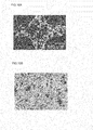
- Fig. 6A is a photomicrograph of an enlarged end surface of the honeycomb structural body of Example 1
- Fig. 6B is a photomicrograph of an enlarged surface of a partition wall in the honeycomb structural body of Example 1.
- Fig. 7A is a photomicrograph of an enlarged end surface of the honeycomb structural body of Example 2
- Fig. 7B is a photomicrograph of an enlarged surface of a partition wall in the honeycomb structural body of Example 2.
- Fig. 8A is a photomicrograph of the enlarged end surface of the honeycomb structural body of Example 3
- Fig. 8B is a photomicrograph of an enlarged surface of a partition wall in the honeycomb structural body of Example 3.
- Fig. 9A is a photomicrograph of an enlarged end surface of the honeycomb structural body of Comparative Example 1
- Fig. 9B is a photomicrograph of an enlarged surface of a partition wall in the honeycomb structural body of Comparative Example 1.
- Fig. 10A is a photomicrograph of an enlarged end surface of the honeycomb structural body of Comparative Example 2
- Fig. 10B is a photomicrograph of an enlarged surface of a partition wall in the honeycomb structural body of Comparative Example 2.
- FIG. 6A , Fig. 7A , Fig. 8A , Fig. 9A and Fig. 10A an about quadrant (1/4) of each cell partitioned by the partition walls is reflected in four portions of the upper right, lower right, upper left and lower left of an image (the photomicrograph).
- the surface of each honeycomb structural body which was vertical to the cell extending direction was photographed at a magnification of 100 times.
- FIG. 6B , Fig. 7B , Fig. 8B , Fig. 9B and Fig. 10B the surface of the partition wall disposed to form the cell is reflected in the section of the honeycomb structural body cut in parallel with the cell extending direction. The surface of the partition wall was photographed at a magnification of 100 times.
- the honeycomb structural bodies of Examples 1 to 6 have a higher strength (A-axis compressive strength) as compared with the honeycomb structural bodies of Comparative Examples 1 to 9.
- A-axis compressive strength the degree of strength of the honeycomb structural bodies
- the porosity of the honeycomb structural bodies can be raised.
- a larger amount of catalyst e.g. the zeolite
- a honeycomb structural body of the present invention can be utilized as a catalyst carrier for loading a catalyst.
Landscapes
- Chemical & Material Sciences (AREA)
- Engineering & Computer Science (AREA)
- Ceramic Engineering (AREA)
- Chemical Kinetics & Catalysis (AREA)
- Physics & Mathematics (AREA)
- Geometry (AREA)
- Organic Chemistry (AREA)
- Structural Engineering (AREA)
- Materials Engineering (AREA)
- Health & Medical Sciences (AREA)
- Toxicology (AREA)
- Combustion & Propulsion (AREA)
- Mechanical Engineering (AREA)
- General Engineering & Computer Science (AREA)
- Catalysts (AREA)
- Manufacturing & Machinery (AREA)
- Exhaust Gas Treatment By Means Of Catalyst (AREA)
- Porous Artificial Stone Or Porous Ceramic Products (AREA)
- Nanotechnology (AREA)
Applications Claiming Priority (1)
| Application Number | Priority Date | Filing Date | Title |
|---|---|---|---|
| US37899210P | 2010-09-01 | 2010-09-01 |
Publications (2)
| Publication Number | Publication Date |
|---|---|
| EP2425888A1 true EP2425888A1 (de) | 2012-03-07 |
| EP2425888B1 EP2425888B1 (de) | 2013-10-02 |
Family
ID=44719243
Family Applications (1)
| Application Number | Title | Priority Date | Filing Date |
|---|---|---|---|
| EP11177064.0A Active EP2425888B1 (de) | 2010-09-01 | 2011-08-10 | Wabenstrukturkörper |
Country Status (3)
| Country | Link |
|---|---|
| US (1) | US9091197B2 (de) |
| EP (1) | EP2425888B1 (de) |
| JP (1) | JP5405538B2 (de) |
Cited By (6)
| Publication number | Priority date | Publication date | Assignee | Title |
|---|---|---|---|---|
| EP2505570A1 (de) * | 2011-03-30 | 2012-10-03 | NGK Insulators, Ltd. | Wabenstruktur, Herstellungsverfahren dafür und Katalysator mit der Wabenstruktur |
| EP2641888A1 (de) * | 2012-03-19 | 2013-09-25 | NGK Insulators, Ltd. | Wabenkörper-struktur, wabenförmiger katalisator damit, verfahren zur herstellung einer wabenkörper-struktur |
| JP2013189358A (ja) * | 2012-03-15 | 2013-09-26 | Ngk Insulators Ltd | ハニカム構造体、及びハニカム触媒体 |
| CN104661730A (zh) * | 2012-04-13 | 2015-05-27 | 优美科股份公司及两合公司 | 用于汽油车辆的污染物减少系统 |
| CN105008050A (zh) * | 2013-04-02 | 2015-10-28 | 日立金属株式会社 | 陶瓷蜂窝结构体及其制造方法 |
| EP2735368A3 (de) * | 2012-11-27 | 2016-07-06 | NGK Insulators, Ltd. | Wabenförmiger Katalysatorkörper |
Families Citing this family (16)
| Publication number | Priority date | Publication date | Assignee | Title |
|---|---|---|---|---|
| JP6106997B2 (ja) * | 2012-08-31 | 2017-04-05 | 日立金属株式会社 | セラミックハニカム構造体及びその製造方法 |
| JP5843802B2 (ja) * | 2013-03-21 | 2016-01-13 | 日本碍子株式会社 | ハニカム触媒担体 |
| JP5667663B2 (ja) * | 2013-06-24 | 2015-02-12 | 日本碍子株式会社 | ハニカム構造体 |
| US9463447B2 (en) * | 2014-01-29 | 2016-10-11 | Ford Global Technologies, Llc | Hydrocarbon trap with increased zeolite loading and improved adsorption capacity |
| JP2019515859A (ja) | 2016-03-17 | 2019-06-13 | コーニング インコーポレイテッド | 高空隙率のセラミックハニカム構造及び製造方法 |
| JP6622134B2 (ja) * | 2016-03-31 | 2019-12-18 | 日本碍子株式会社 | ハニカム構造体及びハニカム構造体の製造方法 |
| JP6788515B2 (ja) * | 2017-02-02 | 2020-11-25 | 日本碍子株式会社 | 目封止ハニカム構造体 |
| JP2018143905A (ja) * | 2017-03-01 | 2018-09-20 | 日本碍子株式会社 | ハニカム触媒体 |
| JP6802096B2 (ja) * | 2017-03-14 | 2020-12-16 | 日本碍子株式会社 | 目封止ハニカム構造体 |
| JP6982530B2 (ja) * | 2018-03-23 | 2021-12-17 | 日本碍子株式会社 | ハニカム構造体 |
| WO2020039649A1 (ja) * | 2018-08-22 | 2020-02-27 | 三井金属鉱業株式会社 | 排ガス浄化用触媒 |
| JP7274395B2 (ja) * | 2019-10-11 | 2023-05-16 | 日本碍子株式会社 | ハニカム構造体 |
| JP7449721B2 (ja) * | 2020-03-02 | 2024-03-14 | 日本碍子株式会社 | ハニカムフィルタ |
| JP7353218B2 (ja) * | 2020-03-02 | 2023-09-29 | 日本碍子株式会社 | ハニカムフィルタ |
| JP7449720B2 (ja) * | 2020-03-02 | 2024-03-14 | 日本碍子株式会社 | ハニカムフィルタ |
| JP7443200B2 (ja) * | 2020-09-03 | 2024-03-05 | 日本碍子株式会社 | 多孔質セラミックス構造体 |
Citations (6)
| Publication number | Priority date | Publication date | Assignee | Title |
|---|---|---|---|---|
| EP1985352A2 (de) * | 2007-04-27 | 2008-10-29 | Ngk Insulators, Ltd. | Wabenfiltersystem |
| JP4246475B2 (ja) | 2002-04-26 | 2009-04-02 | 日本碍子株式会社 | ハニカム構造体の製造方法 |
| EP2108494A2 (de) * | 2008-04-11 | 2009-10-14 | Ngk Insulators, Ltd. | Herstellungsverfahren für eine Wabenstruktur |
| JP2009242133A (ja) | 2008-03-28 | 2009-10-22 | Ngk Insulators Ltd | ハニカム構造体の製造方法 |
| EP2158956A1 (de) * | 2007-04-27 | 2010-03-03 | Ngk Insulator, Ltd. | Wabenfilter |
| EP2216085A1 (de) * | 2009-01-22 | 2010-08-11 | NGK Insulators, Ltd. | Katalytischer Wabenartikel |
Family Cites Families (7)
| Publication number | Priority date | Publication date | Assignee | Title |
|---|---|---|---|---|
| JPS647935A (en) * | 1987-06-30 | 1989-01-11 | Nissan Motor | Catalytic converter device |
| JPH01159029A (ja) * | 1987-12-16 | 1989-06-22 | Toyota Motor Corp | ディーゼルエンジンの排気浄化装置 |
| JP3363564B2 (ja) * | 1994-02-04 | 2003-01-08 | トヨタ自動車株式会社 | 排ガス浄化用触媒 |
| WO2006041174A1 (ja) * | 2004-10-12 | 2006-04-20 | Ibiden Co., Ltd. | セラミックハニカム構造体 |
| JPWO2007094379A1 (ja) * | 2006-02-14 | 2009-07-09 | 日本碍子株式会社 | ハニカム構造体及びハニカム触媒体 |
| JP2009255047A (ja) * | 2008-03-24 | 2009-11-05 | Ibiden Co Ltd | ハニカム構造体 |
| US8815189B2 (en) * | 2010-04-19 | 2014-08-26 | Basf Corporation | Gasoline engine emissions treatment systems having particulate filters |
-
2011
- 2011-08-03 JP JP2011169900A patent/JP5405538B2/ja active Active
- 2011-08-10 US US13/206,863 patent/US9091197B2/en active Active
- 2011-08-10 EP EP11177064.0A patent/EP2425888B1/de active Active
Patent Citations (6)
| Publication number | Priority date | Publication date | Assignee | Title |
|---|---|---|---|---|
| JP4246475B2 (ja) | 2002-04-26 | 2009-04-02 | 日本碍子株式会社 | ハニカム構造体の製造方法 |
| EP1985352A2 (de) * | 2007-04-27 | 2008-10-29 | Ngk Insulators, Ltd. | Wabenfiltersystem |
| EP2158956A1 (de) * | 2007-04-27 | 2010-03-03 | Ngk Insulator, Ltd. | Wabenfilter |
| JP2009242133A (ja) | 2008-03-28 | 2009-10-22 | Ngk Insulators Ltd | ハニカム構造体の製造方法 |
| EP2108494A2 (de) * | 2008-04-11 | 2009-10-14 | Ngk Insulators, Ltd. | Herstellungsverfahren für eine Wabenstruktur |
| EP2216085A1 (de) * | 2009-01-22 | 2010-08-11 | NGK Insulators, Ltd. | Katalytischer Wabenartikel |
Cited By (14)
| Publication number | Priority date | Publication date | Assignee | Title |
|---|---|---|---|---|
| US9174880B2 (en) | 2011-03-30 | 2015-11-03 | Ngk Insulators, Ltd. | Honeycomb structure, manufacturing method thereof, and catalyst carrying honeycomb structure |
| EP2505570A1 (de) * | 2011-03-30 | 2012-10-03 | NGK Insulators, Ltd. | Wabenstruktur, Herstellungsverfahren dafür und Katalysator mit der Wabenstruktur |
| US8722172B2 (en) | 2011-03-30 | 2014-05-13 | Ngk Insulators, Ltd. | Honeycomb structure, manufacturing method thereof, and catalyst carrying honeycomb structure |
| EP3424892A1 (de) * | 2011-03-30 | 2019-01-09 | NGK Insulators, Ltd. | Wabenstruktur, herstellungsverfahren dafür und katalysator mit wabenstruktur |
| JP2013189358A (ja) * | 2012-03-15 | 2013-09-26 | Ngk Insulators Ltd | ハニカム構造体、及びハニカム触媒体 |
| US9248440B2 (en) | 2012-03-19 | 2016-02-02 | Ngk Insulators, Ltd. | Honeycomb structure, honeycomb catalyst body using the same, and manufacturing method of honeycomb structure |
| EP2641888A1 (de) * | 2012-03-19 | 2013-09-25 | NGK Insulators, Ltd. | Wabenkörper-struktur, wabenförmiger katalisator damit, verfahren zur herstellung einer wabenkörper-struktur |
| CN104661730A (zh) * | 2012-04-13 | 2015-05-27 | 优美科股份公司及两合公司 | 用于汽油车辆的污染物减少系统 |
| CN104661730B (zh) * | 2012-04-13 | 2016-10-26 | 优美科股份公司及两合公司 | 用于汽油车辆的污染物减少系统 |
| US9464551B2 (en) | 2012-11-27 | 2016-10-11 | Ngk Insulators, Ltd. | Honeycomb catalyst body |
| EP2735368A3 (de) * | 2012-11-27 | 2016-07-06 | NGK Insulators, Ltd. | Wabenförmiger Katalysatorkörper |
| EP2937143A4 (de) * | 2013-04-02 | 2016-09-07 | Hitachi Metals Ltd | Keramikwabenstruktur und verfahren zur herstellung davon |
| CN105008050B (zh) * | 2013-04-02 | 2017-07-28 | 日立金属株式会社 | 陶瓷蜂窝结构体及其制造方法 |
| CN105008050A (zh) * | 2013-04-02 | 2015-10-28 | 日立金属株式会社 | 陶瓷蜂窝结构体及其制造方法 |
Also Published As
| Publication number | Publication date |
|---|---|
| US9091197B2 (en) | 2015-07-28 |
| EP2425888B1 (de) | 2013-10-02 |
| US20120064286A1 (en) | 2012-03-15 |
| JP5405538B2 (ja) | 2014-02-05 |
| JP2012050978A (ja) | 2012-03-15 |
Similar Documents
| Publication | Publication Date | Title |
|---|---|---|
| US9091197B2 (en) | Honeycomb structural body | |
| EP2572771B1 (de) | Wabenstruktur und wabenförmiger katalytischer Körper | |
| US7208108B2 (en) | Method for producing porous ceramic article | |
| EP2343113B1 (de) | Bienenwabenstruktur | |
| EP2705891B1 (de) | Abgedichtete Wabenstruktur | |
| EP2505570B1 (de) | Wabenstruktur, Herstellungsverfahren dafür und Katalysator mit der Wabenstruktur | |
| EP2853708B1 (de) | Wabenstruktur | |
| US9340463B2 (en) | Honeycomb structure | |
| EP2604323A1 (de) | Wabenfilter und herstellungsverfahren dafür | |
| EP2380649A1 (de) | Abgasreinigungsvorrichtung | |
| EP2957548B1 (de) | Wabenstruktur | |
| US20100242426A1 (en) | Ceramic honeycomb structure | |
| WO2009118875A1 (ja) | ハニカム構造体 | |
| EP2636449A2 (de) | Wabenstruktur und wabenförmiger Katalysator | |
| CN114950029B (zh) | 多孔质蜂窝结构体及其制造方法 | |
| EP2644244A2 (de) | Wabenstruktur | |
| US20060193756A1 (en) | Honeycomb structure | |
| EP2399670A1 (de) | Zeolith-Struktur und Verfahren zu deren Herstellung | |
| EP2735368B1 (de) | Wabenförmiger katalysatorkörper | |
| CN108625959B (zh) | 蜂窝结构体 | |
| EP2698190A1 (de) | Abgedichtete Wabenstruktur | |
| EP2572770B1 (de) | Wabenförmiger Katalysatorkörper | |
| CN108568159B (zh) | 蜂窝结构体 | |
| EP2638947B1 (de) | Wabenstruktur und wabenförmiger katalysator | |
| US20230356131A1 (en) | Honeycomb filter |
Legal Events
| Date | Code | Title | Description |
|---|---|---|---|
| AK | Designated contracting states |
Kind code of ref document: A1 Designated state(s): AL AT BE BG CH CY CZ DE DK EE ES FI FR GB GR HR HU IE IS IT LI LT LU LV MC MK MT NL NO PL PT RO RS SE SI SK SM TR |
|
| AX | Request for extension of the european patent |
Extension state: BA ME |
|
| PUAI | Public reference made under article 153(3) epc to a published international application that has entered the european phase |
Free format text: ORIGINAL CODE: 0009012 |
|
| 17P | Request for examination filed |
Effective date: 20120831 |
|
| RIC1 | Information provided on ipc code assigned before grant |
Ipc: C04B 38/00 20060101ALI20130131BHEP Ipc: B01D 53/94 20060101AFI20130131BHEP Ipc: F01N 3/035 20060101ALI20130131BHEP Ipc: F01N 3/022 20060101ALI20130131BHEP |
|
| GRAP | Despatch of communication of intention to grant a patent |
Free format text: ORIGINAL CODE: EPIDOSNIGR1 |
|
| INTG | Intention to grant announced |
Effective date: 20130426 |
|
| GRAS | Grant fee paid |
Free format text: ORIGINAL CODE: EPIDOSNIGR3 |
|
| GRAA | (expected) grant |
Free format text: ORIGINAL CODE: 0009210 |
|
| AK | Designated contracting states |
Kind code of ref document: B1 Designated state(s): AL AT BE BG CH CY CZ DE DK EE ES FI FR GB GR HR HU IE IS IT LI LT LU LV MC MK MT NL NO PL PT RO RS SE SI SK SM TR |
|
| REG | Reference to a national code |
Ref country code: GB Ref legal event code: FG4D |
|
| REG | Reference to a national code |
Ref country code: CH Ref legal event code: EP Ref country code: AT Ref legal event code: REF Ref document number: 634314 Country of ref document: AT Kind code of ref document: T Effective date: 20131015 |
|
| REG | Reference to a national code |
Ref country code: IE Ref legal event code: FG4D |
|
| REG | Reference to a national code |
Ref country code: DE Ref legal event code: R096 Ref document number: 602011003243 Country of ref document: DE Effective date: 20131128 |
|
| REG | Reference to a national code |
Ref country code: AT Ref legal event code: MK05 Ref document number: 634314 Country of ref document: AT Kind code of ref document: T Effective date: 20131002 |
|
| REG | Reference to a national code |
Ref country code: NL Ref legal event code: VDEP Effective date: 20131002 |
|
| PG25 | Lapsed in a contracting state [announced via postgrant information from national office to epo] |
Ref country code: SI Free format text: LAPSE BECAUSE OF FAILURE TO SUBMIT A TRANSLATION OF THE DESCRIPTION OR TO PAY THE FEE WITHIN THE PRESCRIBED TIME-LIMIT Effective date: 20131002 |
|
| REG | Reference to a national code |
Ref country code: LT Ref legal event code: MG4D |
|
| PG25 | Lapsed in a contracting state [announced via postgrant information from national office to epo] |
Ref country code: IS Free format text: LAPSE BECAUSE OF FAILURE TO SUBMIT A TRANSLATION OF THE DESCRIPTION OR TO PAY THE FEE WITHIN THE PRESCRIBED TIME-LIMIT Effective date: 20140202 Ref country code: CZ Free format text: LAPSE BECAUSE OF FAILURE TO SUBMIT A TRANSLATION OF THE DESCRIPTION OR TO PAY THE FEE WITHIN THE PRESCRIBED TIME-LIMIT Effective date: 20131002 Ref country code: NO Free format text: LAPSE BECAUSE OF FAILURE TO SUBMIT A TRANSLATION OF THE DESCRIPTION OR TO PAY THE FEE WITHIN THE PRESCRIBED TIME-LIMIT Effective date: 20140102 Ref country code: SE Free format text: LAPSE BECAUSE OF FAILURE TO SUBMIT A TRANSLATION OF THE DESCRIPTION OR TO PAY THE FEE WITHIN THE PRESCRIBED TIME-LIMIT Effective date: 20131002 Ref country code: BE Free format text: LAPSE BECAUSE OF FAILURE TO SUBMIT A TRANSLATION OF THE DESCRIPTION OR TO PAY THE FEE WITHIN THE PRESCRIBED TIME-LIMIT Effective date: 20131002 Ref country code: LT Free format text: LAPSE BECAUSE OF FAILURE TO SUBMIT A TRANSLATION OF THE DESCRIPTION OR TO PAY THE FEE WITHIN THE PRESCRIBED TIME-LIMIT Effective date: 20131002 Ref country code: NL Free format text: LAPSE BECAUSE OF FAILURE TO SUBMIT A TRANSLATION OF THE DESCRIPTION OR TO PAY THE FEE WITHIN THE PRESCRIBED TIME-LIMIT Effective date: 20131002 Ref country code: HR Free format text: LAPSE BECAUSE OF FAILURE TO SUBMIT A TRANSLATION OF THE DESCRIPTION OR TO PAY THE FEE WITHIN THE PRESCRIBED TIME-LIMIT Effective date: 20131002 Ref country code: FI Free format text: LAPSE BECAUSE OF FAILURE TO SUBMIT A TRANSLATION OF THE DESCRIPTION OR TO PAY THE FEE WITHIN THE PRESCRIBED TIME-LIMIT Effective date: 20131002 |
|
| PG25 | Lapsed in a contracting state [announced via postgrant information from national office to epo] |
Ref country code: LV Free format text: LAPSE BECAUSE OF FAILURE TO SUBMIT A TRANSLATION OF THE DESCRIPTION OR TO PAY THE FEE WITHIN THE PRESCRIBED TIME-LIMIT Effective date: 20131002 Ref country code: AT Free format text: LAPSE BECAUSE OF FAILURE TO SUBMIT A TRANSLATION OF THE DESCRIPTION OR TO PAY THE FEE WITHIN THE PRESCRIBED TIME-LIMIT Effective date: 20131002 Ref country code: CY Free format text: LAPSE BECAUSE OF FAILURE TO SUBMIT A TRANSLATION OF THE DESCRIPTION OR TO PAY THE FEE WITHIN THE PRESCRIBED TIME-LIMIT Effective date: 20131002 Ref country code: PL Free format text: LAPSE BECAUSE OF FAILURE TO SUBMIT A TRANSLATION OF THE DESCRIPTION OR TO PAY THE FEE WITHIN THE PRESCRIBED TIME-LIMIT Effective date: 20131002 Ref country code: RS Free format text: LAPSE BECAUSE OF FAILURE TO SUBMIT A TRANSLATION OF THE DESCRIPTION OR TO PAY THE FEE WITHIN THE PRESCRIBED TIME-LIMIT Effective date: 20131002 Ref country code: ES Free format text: LAPSE BECAUSE OF FAILURE TO SUBMIT A TRANSLATION OF THE DESCRIPTION OR TO PAY THE FEE WITHIN THE PRESCRIBED TIME-LIMIT Effective date: 20131002 |
|
| PG25 | Lapsed in a contracting state [announced via postgrant information from national office to epo] |
Ref country code: PT Free format text: LAPSE BECAUSE OF FAILURE TO SUBMIT A TRANSLATION OF THE DESCRIPTION OR TO PAY THE FEE WITHIN THE PRESCRIBED TIME-LIMIT Effective date: 20140203 |
|
| REG | Reference to a national code |
Ref country code: DE Ref legal event code: R097 Ref document number: 602011003243 Country of ref document: DE |
|
| PG25 | Lapsed in a contracting state [announced via postgrant information from national office to epo] |
Ref country code: EE Free format text: LAPSE BECAUSE OF FAILURE TO SUBMIT A TRANSLATION OF THE DESCRIPTION OR TO PAY THE FEE WITHIN THE PRESCRIBED TIME-LIMIT Effective date: 20131002 |
|
| PLBE | No opposition filed within time limit |
Free format text: ORIGINAL CODE: 0009261 |
|
| STAA | Information on the status of an ep patent application or granted ep patent |
Free format text: STATUS: NO OPPOSITION FILED WITHIN TIME LIMIT |
|
| PG25 | Lapsed in a contracting state [announced via postgrant information from national office to epo] |
Ref country code: IT Free format text: LAPSE BECAUSE OF FAILURE TO SUBMIT A TRANSLATION OF THE DESCRIPTION OR TO PAY THE FEE WITHIN THE PRESCRIBED TIME-LIMIT Effective date: 20131002 Ref country code: RO Free format text: LAPSE BECAUSE OF FAILURE TO SUBMIT A TRANSLATION OF THE DESCRIPTION OR TO PAY THE FEE WITHIN THE PRESCRIBED TIME-LIMIT Effective date: 20131002 Ref country code: SK Free format text: LAPSE BECAUSE OF FAILURE TO SUBMIT A TRANSLATION OF THE DESCRIPTION OR TO PAY THE FEE WITHIN THE PRESCRIBED TIME-LIMIT Effective date: 20131002 |
|
| 26N | No opposition filed |
Effective date: 20140703 |
|
| PG25 | Lapsed in a contracting state [announced via postgrant information from national office to epo] |
Ref country code: DK Free format text: LAPSE BECAUSE OF FAILURE TO SUBMIT A TRANSLATION OF THE DESCRIPTION OR TO PAY THE FEE WITHIN THE PRESCRIBED TIME-LIMIT Effective date: 20131002 |
|
| REG | Reference to a national code |
Ref country code: DE Ref legal event code: R097 Ref document number: 602011003243 Country of ref document: DE Effective date: 20140703 |
|
| PG25 | Lapsed in a contracting state [announced via postgrant information from national office to epo] |
Ref country code: MC Free format text: LAPSE BECAUSE OF FAILURE TO SUBMIT A TRANSLATION OF THE DESCRIPTION OR TO PAY THE FEE WITHIN THE PRESCRIBED TIME-LIMIT Effective date: 20131002 Ref country code: LU Free format text: LAPSE BECAUSE OF FAILURE TO SUBMIT A TRANSLATION OF THE DESCRIPTION OR TO PAY THE FEE WITHIN THE PRESCRIBED TIME-LIMIT Effective date: 20140810 |
|
| REG | Reference to a national code |
Ref country code: CH Ref legal event code: PL |
|
| PG25 | Lapsed in a contracting state [announced via postgrant information from national office to epo] |
Ref country code: LI Free format text: LAPSE BECAUSE OF NON-PAYMENT OF DUE FEES Effective date: 20140831 Ref country code: CH Free format text: LAPSE BECAUSE OF NON-PAYMENT OF DUE FEES Effective date: 20140831 |
|
| REG | Reference to a national code |
Ref country code: IE Ref legal event code: MM4A |
|
| PG25 | Lapsed in a contracting state [announced via postgrant information from national office to epo] |
Ref country code: IE Free format text: LAPSE BECAUSE OF NON-PAYMENT OF DUE FEES Effective date: 20140810 |
|
| GBPC | Gb: european patent ceased through non-payment of renewal fee |
Effective date: 20150810 |
|
| PG25 | Lapsed in a contracting state [announced via postgrant information from national office to epo] |
Ref country code: NO Free format text: LAPSE BECAUSE OF FAILURE TO SUBMIT A TRANSLATION OF THE DESCRIPTION OR TO PAY THE FEE WITHIN THE PRESCRIBED TIME-LIMIT Effective date: 20140101 Ref country code: SM Free format text: LAPSE BECAUSE OF FAILURE TO SUBMIT A TRANSLATION OF THE DESCRIPTION OR TO PAY THE FEE WITHIN THE PRESCRIBED TIME-LIMIT Effective date: 20131002 |
|
| PG25 | Lapsed in a contracting state [announced via postgrant information from national office to epo] |
Ref country code: BG Free format text: LAPSE BECAUSE OF FAILURE TO SUBMIT A TRANSLATION OF THE DESCRIPTION OR TO PAY THE FEE WITHIN THE PRESCRIBED TIME-LIMIT Effective date: 20131002 Ref country code: MT Free format text: LAPSE BECAUSE OF FAILURE TO SUBMIT A TRANSLATION OF THE DESCRIPTION OR TO PAY THE FEE WITHIN THE PRESCRIBED TIME-LIMIT Effective date: 20131002 Ref country code: GR Free format text: LAPSE BECAUSE OF FAILURE TO SUBMIT A TRANSLATION OF THE DESCRIPTION OR TO PAY THE FEE WITHIN THE PRESCRIBED TIME-LIMIT Effective date: 20140103 |
|
| REG | Reference to a national code |
Ref country code: FR Ref legal event code: PLFP Year of fee payment: 6 |
|
| PG25 | Lapsed in a contracting state [announced via postgrant information from national office to epo] |
Ref country code: HU Free format text: LAPSE BECAUSE OF FAILURE TO SUBMIT A TRANSLATION OF THE DESCRIPTION OR TO PAY THE FEE WITHIN THE PRESCRIBED TIME-LIMIT; INVALID AB INITIO Effective date: 20110810 Ref country code: TR Free format text: LAPSE BECAUSE OF FAILURE TO SUBMIT A TRANSLATION OF THE DESCRIPTION OR TO PAY THE FEE WITHIN THE PRESCRIBED TIME-LIMIT Effective date: 20131002 Ref country code: GB Free format text: LAPSE BECAUSE OF NON-PAYMENT OF DUE FEES Effective date: 20150810 |
|
| REG | Reference to a national code |
Ref country code: FR Ref legal event code: PLFP Year of fee payment: 7 |
|
| PG25 | Lapsed in a contracting state [announced via postgrant information from national office to epo] |
Ref country code: MK Free format text: LAPSE BECAUSE OF FAILURE TO SUBMIT A TRANSLATION OF THE DESCRIPTION OR TO PAY THE FEE WITHIN THE PRESCRIBED TIME-LIMIT Effective date: 20131002 |
|
| REG | Reference to a national code |
Ref country code: FR Ref legal event code: PLFP Year of fee payment: 8 |
|
| PG25 | Lapsed in a contracting state [announced via postgrant information from national office to epo] |
Ref country code: AL Free format text: LAPSE BECAUSE OF FAILURE TO SUBMIT A TRANSLATION OF THE DESCRIPTION OR TO PAY THE FEE WITHIN THE PRESCRIBED TIME-LIMIT Effective date: 20131002 |
|
| PGFP | Annual fee paid to national office [announced via postgrant information from national office to epo] |
Ref country code: DE Payment date: 20250702 Year of fee payment: 15 |
|
| PGFP | Annual fee paid to national office [announced via postgrant information from national office to epo] |
Ref country code: FR Payment date: 20250703 Year of fee payment: 15 |