EP2853708B1 - Wabenstruktur - Google Patents
Wabenstruktur Download PDFInfo
- Publication number
- EP2853708B1 EP2853708B1 EP14186312.6A EP14186312A EP2853708B1 EP 2853708 B1 EP2853708 B1 EP 2853708B1 EP 14186312 A EP14186312 A EP 14186312A EP 2853708 B1 EP2853708 B1 EP 2853708B1
- Authority
- EP
- European Patent Office
- Prior art keywords
- cells
- line segment
- pitch
- honeycomb structure
- cell
- Prior art date
- Legal status (The legal status is an assumption and is not a legal conclusion. Google has not performed a legal analysis and makes no representation as to the accuracy of the status listed.)
- Active
Links
- 210000004027 cell Anatomy 0.000 claims description 516
- 238000005192 partition Methods 0.000 claims description 136
- 230000005484 gravity Effects 0.000 claims description 27
- 210000001316 polygonal cell Anatomy 0.000 claims description 9
- 239000011295 pitch Substances 0.000 description 192
- 230000000052 comparative effect Effects 0.000 description 44
- 230000035939 shock Effects 0.000 description 40
- 239000002994 raw material Substances 0.000 description 36
- 239000000463 material Substances 0.000 description 33
- 239000007789 gas Substances 0.000 description 31
- 238000000034 method Methods 0.000 description 28
- 239000003054 catalyst Substances 0.000 description 25
- 229910052878 cordierite Inorganic materials 0.000 description 19
- 238000011156 evaluation Methods 0.000 description 18
- JSKIRARMQDRGJZ-UHFFFAOYSA-N dimagnesium dioxido-bis[(1-oxido-3-oxo-2,4,6,8,9-pentaoxa-1,3-disila-5,7-dialuminabicyclo[3.3.1]nonan-7-yl)oxy]silane Chemical compound [Mg++].[Mg++].[O-][Si]([O-])(O[Al]1O[Al]2O[Si](=O)O[Si]([O-])(O1)O2)O[Al]1O[Al]2O[Si](=O)O[Si]([O-])(O1)O2 JSKIRARMQDRGJZ-UHFFFAOYSA-N 0.000 description 16
- 238000000746 purification Methods 0.000 description 14
- 239000000919 ceramic Substances 0.000 description 13
- 239000011148 porous material Substances 0.000 description 12
- CPLXHLVBOLITMK-UHFFFAOYSA-N Magnesium oxide Chemical compound [Mg]=O CPLXHLVBOLITMK-UHFFFAOYSA-N 0.000 description 10
- 230000003247 decreasing effect Effects 0.000 description 10
- 238000010304 firing Methods 0.000 description 10
- VYPSYNLAJGMNEJ-UHFFFAOYSA-N Silicium dioxide Chemical compound O=[Si]=O VYPSYNLAJGMNEJ-UHFFFAOYSA-N 0.000 description 9
- 238000001125 extrusion Methods 0.000 description 9
- 239000011230 binding agent Substances 0.000 description 8
- PNEYBMLMFCGWSK-UHFFFAOYSA-N aluminium oxide Inorganic materials [O-2].[O-2].[O-2].[Al+3].[Al+3] PNEYBMLMFCGWSK-UHFFFAOYSA-N 0.000 description 7
- 239000000567 combustion gas Substances 0.000 description 7
- 239000002131 composite material Substances 0.000 description 6
- 238000001035 drying Methods 0.000 description 6
- 238000004519 manufacturing process Methods 0.000 description 6
- 229910010271 silicon carbide Inorganic materials 0.000 description 6
- 230000008642 heat stress Effects 0.000 description 5
- 239000000395 magnesium oxide Substances 0.000 description 5
- ATUOYWHBWRKTHZ-UHFFFAOYSA-N Propane Chemical compound CCC ATUOYWHBWRKTHZ-UHFFFAOYSA-N 0.000 description 4
- 238000009924 canning Methods 0.000 description 4
- 238000001816 cooling Methods 0.000 description 4
- 239000002270 dispersing agent Substances 0.000 description 4
- 238000005516 engineering process Methods 0.000 description 4
- 238000011068 loading method Methods 0.000 description 4
- 239000000377 silicon dioxide Substances 0.000 description 4
- 229910000505 Al2TiO5 Inorganic materials 0.000 description 3
- LYCAIKOWRPUZTN-UHFFFAOYSA-N Ethylene glycol Chemical compound OCCO LYCAIKOWRPUZTN-UHFFFAOYSA-N 0.000 description 3
- XUIMIQQOPSSXEZ-UHFFFAOYSA-N Silicon Chemical compound [Si] XUIMIQQOPSSXEZ-UHFFFAOYSA-N 0.000 description 3
- JFBZPFYRPYOZCQ-UHFFFAOYSA-N [Li].[Al] Chemical compound [Li].[Al] JFBZPFYRPYOZCQ-UHFFFAOYSA-N 0.000 description 3
- 238000001354 calcination Methods 0.000 description 3
- 229910010293 ceramic material Inorganic materials 0.000 description 3
- 230000007423 decrease Effects 0.000 description 3
- KZHJGOXRZJKJNY-UHFFFAOYSA-N dioxosilane;oxo(oxoalumanyloxy)alumane Chemical compound O=[Si]=O.O=[Si]=O.O=[Al]O[Al]=O.O=[Al]O[Al]=O.O=[Al]O[Al]=O KZHJGOXRZJKJNY-UHFFFAOYSA-N 0.000 description 3
- 230000000694 effects Effects 0.000 description 3
- 238000010438 heat treatment Methods 0.000 description 3
- 229910052863 mullite Inorganic materials 0.000 description 3
- 229910000510 noble metal Inorganic materials 0.000 description 3
- AABBHSMFGKYLKE-SNAWJCMRSA-N propan-2-yl (e)-but-2-enoate Chemical compound C\C=C\C(=O)OC(C)C AABBHSMFGKYLKE-SNAWJCMRSA-N 0.000 description 3
- SBEQWOXEGHQIMW-UHFFFAOYSA-N silicon Chemical compound [Si].[Si] SBEQWOXEGHQIMW-UHFFFAOYSA-N 0.000 description 3
- 229910052710 silicon Inorganic materials 0.000 description 3
- 239000010703 silicon Substances 0.000 description 3
- HBMJWWWQQXIZIP-UHFFFAOYSA-N silicon carbide Chemical compound [Si+]#[C-] HBMJWWWQQXIZIP-UHFFFAOYSA-N 0.000 description 3
- 229910052596 spinel Inorganic materials 0.000 description 3
- 239000011029 spinel Substances 0.000 description 3
- 239000004094 surface-active agent Substances 0.000 description 3
- VPSXHKGJZJCWLV-UHFFFAOYSA-N 2-[4-[2-(2,3-dihydro-1H-inden-2-ylamino)pyrimidin-5-yl]-3-(1-ethylpiperidin-4-yl)oxypyrazol-1-yl]-1-(2,4,6,7-tetrahydrotriazolo[4,5-c]pyridin-5-yl)ethanone Chemical compound C1C(CC2=CC=CC=C12)NC1=NC=C(C=N1)C=1C(=NN(C=1)CC(=O)N1CC2=C(CC1)NN=N2)OC1CCN(CC1)CC VPSXHKGJZJCWLV-UHFFFAOYSA-N 0.000 description 2
- VCUFZILGIRCDQQ-KRWDZBQOSA-N N-[[(5S)-2-oxo-3-(2-oxo-3H-1,3-benzoxazol-6-yl)-1,3-oxazolidin-5-yl]methyl]-2-[[3-(trifluoromethoxy)phenyl]methylamino]pyrimidine-5-carboxamide Chemical compound O=C1O[C@H](CN1C1=CC2=C(NC(O2)=O)C=C1)CNC(=O)C=1C=NC(=NC=1)NCC1=CC(=CC=C1)OC(F)(F)F VCUFZILGIRCDQQ-KRWDZBQOSA-N 0.000 description 2
- KDLHZDBZIXYQEI-UHFFFAOYSA-N Palladium Chemical compound [Pd] KDLHZDBZIXYQEI-UHFFFAOYSA-N 0.000 description 2
- MCMNRKCIXSYSNV-UHFFFAOYSA-N Zirconium dioxide Chemical compound O=[Zr]=O MCMNRKCIXSYSNV-UHFFFAOYSA-N 0.000 description 2
- 230000015572 biosynthetic process Effects 0.000 description 2
- 239000000969 carrier Substances 0.000 description 2
- 230000003197 catalytic effect Effects 0.000 description 2
- 238000002276 dielectric drying Methods 0.000 description 2
- 239000012530 fluid Substances 0.000 description 2
- 238000007602 hot air drying Methods 0.000 description 2
- 230000006872 improvement Effects 0.000 description 2
- 239000012535 impurity Substances 0.000 description 2
- QSHDDOUJBYECFT-UHFFFAOYSA-N mercury Chemical compound [Hg] QSHDDOUJBYECFT-UHFFFAOYSA-N 0.000 description 2
- 229910052753 mercury Inorganic materials 0.000 description 2
- 230000003647 oxidation Effects 0.000 description 2
- 238000007254 oxidation reaction Methods 0.000 description 2
- 239000013618 particulate matter Substances 0.000 description 2
- BASFCYQUMIYNBI-UHFFFAOYSA-N platinum Chemical compound [Pt] BASFCYQUMIYNBI-UHFFFAOYSA-N 0.000 description 2
- -1 polyethylene Polymers 0.000 description 2
- 239000001294 propane Substances 0.000 description 2
- 230000009467 reduction Effects 0.000 description 2
- 239000002002 slurry Substances 0.000 description 2
- 239000000454 talc Substances 0.000 description 2
- 229910052623 talc Inorganic materials 0.000 description 2
- XLYOFNOQVPJJNP-UHFFFAOYSA-N water Substances O XLYOFNOQVPJJNP-UHFFFAOYSA-N 0.000 description 2
- LNAZSHAWQACDHT-XIYTZBAFSA-N (2r,3r,4s,5r,6s)-4,5-dimethoxy-2-(methoxymethyl)-3-[(2s,3r,4s,5r,6r)-3,4,5-trimethoxy-6-(methoxymethyl)oxan-2-yl]oxy-6-[(2r,3r,4s,5r,6r)-4,5,6-trimethoxy-2-(methoxymethyl)oxan-3-yl]oxyoxane Chemical compound CO[C@@H]1[C@@H](OC)[C@H](OC)[C@@H](COC)O[C@H]1O[C@H]1[C@H](OC)[C@@H](OC)[C@H](O[C@H]2[C@@H]([C@@H](OC)[C@H](OC)O[C@@H]2COC)OC)O[C@@H]1COC LNAZSHAWQACDHT-XIYTZBAFSA-N 0.000 description 1
- KNDAEDDIIQYRHY-UHFFFAOYSA-N 2-[4-[2-(2,3-dihydro-1H-inden-2-ylamino)pyrimidin-5-yl]-3-(piperazin-1-ylmethyl)pyrazol-1-yl]-1-(2,4,6,7-tetrahydrotriazolo[4,5-c]pyridin-5-yl)ethanone Chemical compound C1C(CC2=CC=CC=C12)NC1=NC=C(C=N1)C=1C(=NN(C=1)CC(=O)N1CC2=C(CC1)NN=N2)CN1CCNCC1 KNDAEDDIIQYRHY-UHFFFAOYSA-N 0.000 description 1
- DCVGCQPXTOSWEA-UHFFFAOYSA-N 4-[[4-[2-(2,3-dihydro-1H-inden-2-ylamino)pyrimidin-5-yl]-1-[2-oxo-2-(2,4,6,7-tetrahydrotriazolo[4,5-c]pyridin-5-yl)ethyl]pyrazol-3-yl]methyl]-1-methylpiperazin-2-one Chemical compound CN1CCN(CC2=NN(CC(=O)N3CCC4=C(C3)N=NN4)C=C2C2=CN=C(NC3CC4=C(C3)C=CC=C4)N=C2)CC1=O DCVGCQPXTOSWEA-UHFFFAOYSA-N 0.000 description 1
- OKTJSMMVPCPJKN-UHFFFAOYSA-N Carbon Chemical compound [C] OKTJSMMVPCPJKN-UHFFFAOYSA-N 0.000 description 1
- 229920002134 Carboxymethyl cellulose Polymers 0.000 description 1
- 229920001353 Dextrin Polymers 0.000 description 1
- 239000004375 Dextrin Substances 0.000 description 1
- 229920000663 Hydroxyethyl cellulose Polymers 0.000 description 1
- 239000004354 Hydroxyethyl cellulose Substances 0.000 description 1
- 241000257303 Hymenoptera Species 0.000 description 1
- KKCBUQHMOMHUOY-UHFFFAOYSA-N Na2O Inorganic materials [O-2].[Na+].[Na+] KKCBUQHMOMHUOY-UHFFFAOYSA-N 0.000 description 1
- 239000004698 Polyethylene Substances 0.000 description 1
- 239000004372 Polyvinyl alcohol Substances 0.000 description 1
- 229920002472 Starch Polymers 0.000 description 1
- 229910000831 Steel Inorganic materials 0.000 description 1
- 229910021536 Zeolite Inorganic materials 0.000 description 1
- FHKPLLOSJHHKNU-INIZCTEOSA-N [(3S)-3-[8-(1-ethyl-5-methylpyrazol-4-yl)-9-methylpurin-6-yl]oxypyrrolidin-1-yl]-(oxan-4-yl)methanone Chemical compound C(C)N1N=CC(=C1C)C=1N(C2=NC=NC(=C2N=1)O[C@@H]1CN(CC1)C(=O)C1CCOCC1)C FHKPLLOSJHHKNU-INIZCTEOSA-N 0.000 description 1
- 230000001133 acceleration Effects 0.000 description 1
- WNROFYMDJYEPJX-UHFFFAOYSA-K aluminium hydroxide Chemical compound [OH-].[OH-].[OH-].[Al+3] WNROFYMDJYEPJX-UHFFFAOYSA-K 0.000 description 1
- 239000012298 atmosphere Substances 0.000 description 1
- ODINCKMPIJJUCX-UHFFFAOYSA-N calcium oxide Inorganic materials [Ca]=O ODINCKMPIJJUCX-UHFFFAOYSA-N 0.000 description 1
- CETPSERCERDGAM-UHFFFAOYSA-N ceric oxide Chemical compound O=[Ce]=O CETPSERCERDGAM-UHFFFAOYSA-N 0.000 description 1
- 229910000422 cerium(IV) oxide Inorganic materials 0.000 description 1
- 230000008859 change Effects 0.000 description 1
- 238000002485 combustion reaction Methods 0.000 description 1
- 239000012141 concentrate Substances 0.000 description 1
- 230000008602 contraction Effects 0.000 description 1
- 230000007797 corrosion Effects 0.000 description 1
- 238000005260 corrosion Methods 0.000 description 1
- 239000013078 crystal Substances 0.000 description 1
- 238000005238 degreasing Methods 0.000 description 1
- 235000019425 dextrin Nutrition 0.000 description 1
- 235000014113 dietary fatty acids Nutrition 0.000 description 1
- HNPSIPDUKPIQMN-UHFFFAOYSA-N dioxosilane;oxo(oxoalumanyloxy)alumane Chemical class O=[Si]=O.O=[Al]O[Al]=O HNPSIPDUKPIQMN-UHFFFAOYSA-N 0.000 description 1
- 230000007613 environmental effect Effects 0.000 description 1
- 239000000194 fatty acid Substances 0.000 description 1
- 229930195729 fatty acid Natural products 0.000 description 1
- 150000004665 fatty acids Chemical class 0.000 description 1
- 235000013312 flour Nutrition 0.000 description 1
- 239000010439 graphite Substances 0.000 description 1
- 229910002804 graphite Inorganic materials 0.000 description 1
- 238000000227 grinding Methods 0.000 description 1
- 235000019447 hydroxyethyl cellulose Nutrition 0.000 description 1
- 239000001866 hydroxypropyl methyl cellulose Substances 0.000 description 1
- 229920003088 hydroxypropyl methyl cellulose Polymers 0.000 description 1
- UFVKGYZPFZQRLF-UHFFFAOYSA-N hydroxypropyl methyl cellulose Chemical compound OC1C(O)C(OC)OC(CO)C1OC1C(O)C(O)C(OC2C(C(O)C(OC3C(C(O)C(O)C(CO)O3)O)C(CO)O2)O)C(CO)O1 UFVKGYZPFZQRLF-UHFFFAOYSA-N 0.000 description 1
- 235000010979 hydroxypropyl methyl cellulose Nutrition 0.000 description 1
- 238000001746 injection moulding Methods 0.000 description 1
- JEIPFZHSYJVQDO-UHFFFAOYSA-N iron(III) oxide Inorganic materials O=[Fe]O[Fe]=O JEIPFZHSYJVQDO-UHFFFAOYSA-N 0.000 description 1
- 238000004898 kneading Methods 0.000 description 1
- 239000001095 magnesium carbonate Substances 0.000 description 1
- ZLNQQNXFFQJAID-UHFFFAOYSA-L magnesium carbonate Chemical compound [Mg+2].[O-]C([O-])=O ZLNQQNXFFQJAID-UHFFFAOYSA-L 0.000 description 1
- 229910000021 magnesium carbonate Inorganic materials 0.000 description 1
- 235000014380 magnesium carbonate Nutrition 0.000 description 1
- 238000005259 measurement Methods 0.000 description 1
- 229920000609 methyl cellulose Polymers 0.000 description 1
- 239000001923 methylcellulose Substances 0.000 description 1
- 235000010981 methylcellulose Nutrition 0.000 description 1
- 238000002156 mixing Methods 0.000 description 1
- 239000000203 mixture Substances 0.000 description 1
- 230000004048 modification Effects 0.000 description 1
- 238000012986 modification Methods 0.000 description 1
- 238000000465 moulding Methods 0.000 description 1
- 239000011368 organic material Substances 0.000 description 1
- TWNQGVIAIRXVLR-UHFFFAOYSA-N oxo(oxoalumanyloxy)alumane Chemical compound O=[Al]O[Al]=O TWNQGVIAIRXVLR-UHFFFAOYSA-N 0.000 description 1
- 229910052763 palladium Inorganic materials 0.000 description 1
- 239000002245 particle Substances 0.000 description 1
- 239000005011 phenolic resin Substances 0.000 description 1
- 229910052697 platinum Inorganic materials 0.000 description 1
- 229920003229 poly(methyl methacrylate) Polymers 0.000 description 1
- 229920000573 polyethylene Polymers 0.000 description 1
- 229920000139 polyethylene terephthalate Polymers 0.000 description 1
- 239000005020 polyethylene terephthalate Substances 0.000 description 1
- 229920000642 polymer Polymers 0.000 description 1
- 239000004926 polymethyl methacrylate Substances 0.000 description 1
- 229920002451 polyvinyl alcohol Polymers 0.000 description 1
- NOTVAPJNGZMVSD-UHFFFAOYSA-N potassium monoxide Inorganic materials [K]O[K] NOTVAPJNGZMVSD-UHFFFAOYSA-N 0.000 description 1
- 230000008569 process Effects 0.000 description 1
- 239000010453 quartz Substances 0.000 description 1
- 229920005989 resin Polymers 0.000 description 1
- 239000011347 resin Substances 0.000 description 1
- 229910052703 rhodium Inorganic materials 0.000 description 1
- 239000010948 rhodium Substances 0.000 description 1
- MHOVAHRLVXNVSD-UHFFFAOYSA-N rhodium atom Chemical compound [Rh] MHOVAHRLVXNVSD-UHFFFAOYSA-N 0.000 description 1
- 238000005245 sintering Methods 0.000 description 1
- 239000000344 soap Substances 0.000 description 1
- 239000007787 solid Substances 0.000 description 1
- 229910001220 stainless steel Inorganic materials 0.000 description 1
- 239000010935 stainless steel Substances 0.000 description 1
- 239000008107 starch Substances 0.000 description 1
- 235000019698 starch Nutrition 0.000 description 1
- 239000010959 steel Substances 0.000 description 1
- 238000003860 storage Methods 0.000 description 1
- 239000000126 substance Substances 0.000 description 1
- 150000005846 sugar alcohols Polymers 0.000 description 1
- 239000000057 synthetic resin Substances 0.000 description 1
- 229920003002 synthetic resin Polymers 0.000 description 1
- 238000001291 vacuum drying Methods 0.000 description 1
- 238000009777 vacuum freeze-drying Methods 0.000 description 1
- 239000010457 zeolite Substances 0.000 description 1
Images


Classifications
-
- C—CHEMISTRY; METALLURGY
- C04—CEMENTS; CONCRETE; ARTIFICIAL STONE; CERAMICS; REFRACTORIES
- C04B—LIME, MAGNESIA; SLAG; CEMENTS; COMPOSITIONS THEREOF, e.g. MORTARS, CONCRETE OR LIKE BUILDING MATERIALS; ARTIFICIAL STONE; CERAMICS; REFRACTORIES; TREATMENT OF NATURAL STONE
- C04B38/00—Porous mortars, concrete, artificial stone or ceramic ware; Preparation thereof
- C04B38/0006—Honeycomb structures
- C04B38/0009—Honeycomb structures characterised by features relating to the cell walls, e.g. wall thickness or distribution of pores in the walls
-
- F—MECHANICAL ENGINEERING; LIGHTING; HEATING; WEAPONS; BLASTING
- F01—MACHINES OR ENGINES IN GENERAL; ENGINE PLANTS IN GENERAL; STEAM ENGINES
- F01N—GAS-FLOW SILENCERS OR EXHAUST APPARATUS FOR MACHINES OR ENGINES IN GENERAL; GAS-FLOW SILENCERS OR EXHAUST APPARATUS FOR INTERNAL COMBUSTION ENGINES
- F01N3/00—Exhaust or silencing apparatus having means for purifying, rendering innocuous, or otherwise treating exhaust
- F01N3/08—Exhaust or silencing apparatus having means for purifying, rendering innocuous, or otherwise treating exhaust for rendering innocuous
- F01N3/10—Exhaust or silencing apparatus having means for purifying, rendering innocuous, or otherwise treating exhaust for rendering innocuous by thermal or catalytic conversion of noxious components of exhaust
- F01N3/24—Exhaust or silencing apparatus having means for purifying, rendering innocuous, or otherwise treating exhaust for rendering innocuous by thermal or catalytic conversion of noxious components of exhaust characterised by constructional aspects of converting apparatus
- F01N3/28—Construction of catalytic reactors
- F01N3/2803—Construction of catalytic reactors characterised by structure, by material or by manufacturing of catalyst support
- F01N3/2825—Ceramics
- F01N3/2828—Ceramic multi-channel monoliths, e.g. honeycombs
-
- B—PERFORMING OPERATIONS; TRANSPORTING
- B01—PHYSICAL OR CHEMICAL PROCESSES OR APPARATUS IN GENERAL
- B01D—SEPARATION
- B01D46/00—Filters or filtering processes specially modified for separating dispersed particles from gases or vapours
- B01D46/24—Particle separators, e.g. dust precipitators, using rigid hollow filter bodies
- B01D46/2403—Particle separators, e.g. dust precipitators, using rigid hollow filter bodies characterised by the physical shape or structure of the filtering element
- B01D46/2418—Honeycomb filters
- B01D46/2451—Honeycomb filters characterized by the geometrical structure, shape, pattern or configuration or parameters related to the geometry of the structure
- B01D46/247—Honeycomb filters characterized by the geometrical structure, shape, pattern or configuration or parameters related to the geometry of the structure of the cells
-
- B—PERFORMING OPERATIONS; TRANSPORTING
- B01—PHYSICAL OR CHEMICAL PROCESSES OR APPARATUS IN GENERAL
- B01D—SEPARATION
- B01D46/00—Filters or filtering processes specially modified for separating dispersed particles from gases or vapours
- B01D46/24—Particle separators, e.g. dust precipitators, using rigid hollow filter bodies
- B01D46/2403—Particle separators, e.g. dust precipitators, using rigid hollow filter bodies characterised by the physical shape or structure of the filtering element
- B01D46/2418—Honeycomb filters
- B01D46/2451—Honeycomb filters characterized by the geometrical structure, shape, pattern or configuration or parameters related to the geometry of the structure
- B01D46/2474—Honeycomb filters characterized by the geometrical structure, shape, pattern or configuration or parameters related to the geometry of the structure of the walls along the length of the honeycomb
-
- B—PERFORMING OPERATIONS; TRANSPORTING
- B01—PHYSICAL OR CHEMICAL PROCESSES OR APPARATUS IN GENERAL
- B01D—SEPARATION
- B01D46/00—Filters or filtering processes specially modified for separating dispersed particles from gases or vapours
- B01D46/24—Particle separators, e.g. dust precipitators, using rigid hollow filter bodies
- B01D46/2403—Particle separators, e.g. dust precipitators, using rigid hollow filter bodies characterised by the physical shape or structure of the filtering element
- B01D46/2418—Honeycomb filters
- B01D46/2451—Honeycomb filters characterized by the geometrical structure, shape, pattern or configuration or parameters related to the geometry of the structure
- B01D46/2482—Thickness, height, width, length or diameter
-
- B—PERFORMING OPERATIONS; TRANSPORTING
- B01—PHYSICAL OR CHEMICAL PROCESSES OR APPARATUS IN GENERAL
- B01D—SEPARATION
- B01D46/00—Filters or filtering processes specially modified for separating dispersed particles from gases or vapours
- B01D46/24—Particle separators, e.g. dust precipitators, using rigid hollow filter bodies
- B01D46/2403—Particle separators, e.g. dust precipitators, using rigid hollow filter bodies characterised by the physical shape or structure of the filtering element
- B01D46/2418—Honeycomb filters
- B01D46/2451—Honeycomb filters characterized by the geometrical structure, shape, pattern or configuration or parameters related to the geometry of the structure
- B01D46/2486—Honeycomb filters characterized by the geometrical structure, shape, pattern or configuration or parameters related to the geometry of the structure characterised by the shapes or configurations
-
- F—MECHANICAL ENGINEERING; LIGHTING; HEATING; WEAPONS; BLASTING
- F01—MACHINES OR ENGINES IN GENERAL; ENGINE PLANTS IN GENERAL; STEAM ENGINES
- F01N—GAS-FLOW SILENCERS OR EXHAUST APPARATUS FOR MACHINES OR ENGINES IN GENERAL; GAS-FLOW SILENCERS OR EXHAUST APPARATUS FOR INTERNAL COMBUSTION ENGINES
- F01N3/00—Exhaust or silencing apparatus having means for purifying, rendering innocuous, or otherwise treating exhaust
- F01N3/02—Exhaust or silencing apparatus having means for purifying, rendering innocuous, or otherwise treating exhaust for cooling, or for removing solid constituents of, exhaust
- F01N3/021—Exhaust or silencing apparatus having means for purifying, rendering innocuous, or otherwise treating exhaust for cooling, or for removing solid constituents of, exhaust by means of filters
- F01N3/022—Exhaust or silencing apparatus having means for purifying, rendering innocuous, or otherwise treating exhaust for cooling, or for removing solid constituents of, exhaust by means of filters characterised by specially adapted filtering structure, e.g. honeycomb, mesh or fibrous
- F01N3/0222—Exhaust or silencing apparatus having means for purifying, rendering innocuous, or otherwise treating exhaust for cooling, or for removing solid constituents of, exhaust by means of filters characterised by specially adapted filtering structure, e.g. honeycomb, mesh or fibrous the structure being monolithic, e.g. honeycombs
-
- B—PERFORMING OPERATIONS; TRANSPORTING
- B28—WORKING CEMENT, CLAY, OR STONE
- B28B—SHAPING CLAY OR OTHER CERAMIC COMPOSITIONS; SHAPING SLAG; SHAPING MIXTURES CONTAINING CEMENTITIOUS MATERIAL, e.g. PLASTER
- B28B3/00—Producing shaped articles from the material by using presses; Presses specially adapted therefor
- B28B3/20—Producing shaped articles from the material by using presses; Presses specially adapted therefor wherein the material is extruded
- B28B3/26—Extrusion dies
- B28B3/269—For multi-channeled structures, e.g. honeycomb structures
-
- F—MECHANICAL ENGINEERING; LIGHTING; HEATING; WEAPONS; BLASTING
- F01—MACHINES OR ENGINES IN GENERAL; ENGINE PLANTS IN GENERAL; STEAM ENGINES
- F01N—GAS-FLOW SILENCERS OR EXHAUST APPARATUS FOR MACHINES OR ENGINES IN GENERAL; GAS-FLOW SILENCERS OR EXHAUST APPARATUS FOR INTERNAL COMBUSTION ENGINES
- F01N2260/00—Exhaust treating devices having provisions not otherwise provided for
- F01N2260/10—Exhaust treating devices having provisions not otherwise provided for for avoiding stress caused by expansions or contractions due to temperature variations
-
- F—MECHANICAL ENGINEERING; LIGHTING; HEATING; WEAPONS; BLASTING
- F01—MACHINES OR ENGINES IN GENERAL; ENGINE PLANTS IN GENERAL; STEAM ENGINES
- F01N—GAS-FLOW SILENCERS OR EXHAUST APPARATUS FOR MACHINES OR ENGINES IN GENERAL; GAS-FLOW SILENCERS OR EXHAUST APPARATUS FOR INTERNAL COMBUSTION ENGINES
- F01N2330/00—Structure of catalyst support or particle filter
- F01N2330/06—Ceramic, e.g. monoliths
-
- F—MECHANICAL ENGINEERING; LIGHTING; HEATING; WEAPONS; BLASTING
- F01—MACHINES OR ENGINES IN GENERAL; ENGINE PLANTS IN GENERAL; STEAM ENGINES
- F01N—GAS-FLOW SILENCERS OR EXHAUST APPARATUS FOR MACHINES OR ENGINES IN GENERAL; GAS-FLOW SILENCERS OR EXHAUST APPARATUS FOR INTERNAL COMBUSTION ENGINES
- F01N2330/00—Structure of catalyst support or particle filter
- F01N2330/30—Honeycomb supports characterised by their structural details
- F01N2330/34—Honeycomb supports characterised by their structural details with flow channels of polygonal cross section
-
- F—MECHANICAL ENGINEERING; LIGHTING; HEATING; WEAPONS; BLASTING
- F01—MACHINES OR ENGINES IN GENERAL; ENGINE PLANTS IN GENERAL; STEAM ENGINES
- F01N—GAS-FLOW SILENCERS OR EXHAUST APPARATUS FOR MACHINES OR ENGINES IN GENERAL; GAS-FLOW SILENCERS OR EXHAUST APPARATUS FOR INTERNAL COMBUSTION ENGINES
- F01N2330/00—Structure of catalyst support or particle filter
- F01N2330/60—Discontinuous, uneven properties of filter material, e.g. different material thickness along the longitudinal direction; Higher filter capacity upstream than downstream in same housing
-
- Y—GENERAL TAGGING OF NEW TECHNOLOGICAL DEVELOPMENTS; GENERAL TAGGING OF CROSS-SECTIONAL TECHNOLOGIES SPANNING OVER SEVERAL SECTIONS OF THE IPC; TECHNICAL SUBJECTS COVERED BY FORMER USPC CROSS-REFERENCE ART COLLECTIONS [XRACs] AND DIGESTS
- Y02—TECHNOLOGIES OR APPLICATIONS FOR MITIGATION OR ADAPTATION AGAINST CLIMATE CHANGE
- Y02T—CLIMATE CHANGE MITIGATION TECHNOLOGIES RELATED TO TRANSPORTATION
- Y02T10/00—Road transport of goods or passengers
- Y02T10/10—Internal combustion engine [ICE] based vehicles
- Y02T10/12—Improving ICE efficiencies
-
- Y—GENERAL TAGGING OF NEW TECHNOLOGICAL DEVELOPMENTS; GENERAL TAGGING OF CROSS-SECTIONAL TECHNOLOGIES SPANNING OVER SEVERAL SECTIONS OF THE IPC; TECHNICAL SUBJECTS COVERED BY FORMER USPC CROSS-REFERENCE ART COLLECTIONS [XRACs] AND DIGESTS
- Y10—TECHNICAL SUBJECTS COVERED BY FORMER USPC
- Y10T—TECHNICAL SUBJECTS COVERED BY FORMER US CLASSIFICATION
- Y10T428/00—Stock material or miscellaneous articles
- Y10T428/24—Structurally defined web or sheet [e.g., overall dimension, etc.]
- Y10T428/24149—Honeycomb-like
Definitions
- the present invention relates to a honeycomb structure. More particularly, it relates to a honeycomb structure which is excellent in pressure resisting strength of circumferential portion and in thermal shock resistance.
- honeycomb structures excellent in thermal resistance and corrosion resistance have been employed as carriers for catalyst devices or filters for use as environmental measures, collection of specific material or the like in various fields of chemistry, electric power, steel industry, and the like.
- a structure resembling a honeycomb built by bees is formed by partition walls to define cells that become through channels for a fluid.
- honeycomb structures are used as catalyst carriers onto which catalyst for purification of exhaust gas is loaded in exhaust gas purification devices to purify the exhaust gas discharged from internal combustion engines such as car engines.
- open ends of the cells in both end faces are alternately plugged to obtain plugged honeycomb structures, and the honeycomb structures are also often used as diesel particulate filters to trap particulate matter discharged from diesel engines or the like.
- the honeycomb structure When the exhaust gas is purified by a honeycomb structure, the honeycomb structure is sometimes used, for example, in an exhaust gas purification device in which the honeycomb structure is contained in a can member having an inflow port through which the exhaust gas flows inside and an outflow port through which the purified exhaust gas flows outside.
- the containing of the honeycomb structure into a can member of the exhaust gas purification device as described above may be referred to as "canning".
- Patent Document 1 for a honeycomb structure in which cross sections of cells are hexagonal, there has been described a technology in which a thickness of partition walls of a circumferential portion is set to be larger than a thickness of partition walls of a central portion. Furthermore, in Patent Document 2 and Patent Document 3, for a honeycomb structure in which cross sections of cells are quadrangular, there has been described a technology in which a thickness of partition walls of a circumferential portion is set to be larger than a thickness of partition walls of a central portion. Furthermore, in Patent Document 4, there has been described a technology in which a hydraulic diameter of cells positioned at the edge of at least one of four sides constituting a rectangular or square cross section of a honeycomb structure is made to be smaller than a hydraulic diameter of other cells.
- EP-A-1384507 discloses a honeycomb structure in which a plurality of through-holes extending in the axial direction are formed by a plurality of partition walls.
- the partition walls have different thicknesses.
- the honeycomb structure when used as a catalyst carrier (hereinafter may simply be referred to as "carrier") in an exhaust gas purification device, temperature difference occurs in the carrier when the temperature of the exhaust gas rises and drops. That is, when the temperature of the exhaust gas rises (e.g., during acceleration of a vehicle), temperature of a portion to which the exhaust gas is applied in the central portion of the carrier heightens, and temperature in the vicinity of the circumference lowers. Conversely, when the temperature of the exhaust gas lowers (e.g., during deceleration of the vehicle), the temperature of the portion to which the exhaust gas is applied in the central portion of the carrier lowers, and the temperature in the vicinity of the circumference heightens.
- the temperature of the exhaust gas lowers (e.g., during deceleration of the vehicle)
- the temperature of the portion to which the exhaust gas is applied in the central portion of the carrier lowers, and the temperature in the vicinity of the circumference heightens.
- the present invention has been developed in view of such problem, and an object thereof is to provide a honeycomb structure which is excellent in pressure resisting strength of the circumferential portion and in thermal shock resistance.
- a honeycomb structure of the present invention is excellent in pressure resisting strength of circumferential portion and in thermal shock resistance. That is, the honeycomb structure of the present invention is constituted so that a thickness of partition walls in a circumferential region positioned at an outer side of a central region is larger than a thickness of partition walls in the central region. Therefore, the honeycomb structure is excellent in pressure resisting strength of the circumferential portion. Furthermore, cells of a cell pitch having a size of 70% or more and 95% or less to a cell pitch of the cells formed in the central region are formed in a boundary portion between the central region and the circumferential portion. That is, in the above boundary portion, "small cell-pitch cells" whose cell pitch is relatively small are formed.
- Such “small cell-pitch cells” are formed, so that the thermal shock resistance of the boundary portion improves. Therefore, in the honeycomb structure of the present invention, for example, even when large heat stress is applied to the boundary portion, damages such as cracks are not easily generated in the boundary portion.
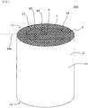
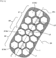
- Fig. 1 is a perspective view schematically showing one embodiment of the honeycomb structure of the present invention.
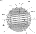
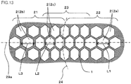
- Fig. 2 is a plan view schematically showing a first end face of the one embodiment of the honeycomb structure of the present invention.
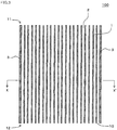
- Fig. 3 is a sectional view schematically showing a cross section parallel to a cell extending direction of the one embodiment of the honeycomb structure of the present invention.
- Fig. 4 is a sectional view schematically showing a cross section cut along the X-X' line of Fig. 3 .
- Fig. 5 is an enlarged sectional view schematically showing a range shown in A of Fig. 4 .
- FIG. 6 is a partially enlarged sectional view in which a part of the cross section shown in Fig. 5 is enlarged.
- Fig. 7 is a partially enlarged sectional view in which another part of the cross section shown in Fig. 5 is enlarged.
- Fig. 8 is a partially enlarged sectional view in which still another part of the cross section shown in Fig. 5 is enlarged.
- a honeycomb structure 100 of the present embodiment includes a tubular honeycomb structure body 10 having porous partition walls 1 to define a plurality of cells 2 extending from a first end face 11 to a second end face 12.
- the honeycomb structure body 10 shown in Fig. 1 to Fig. 4 is cylindrical.
- the honeycomb structure body 10 may have a circumferential wall 3 disposed in the outermost circumference so as to surround the partition walls 1.
- the honeycomb structure 100 has the circumferential wall 3, so that the honeycomb structure is easily contained in a can member of an exhaust gas purification device.
- the partition walls 1 are disposed so that a shape of the cells 2 is polygonal.
- the shape of the cells in the cross section perpendicular to the cell extending direction include a quadrangular shape, a hexagonal shape, an octagonal shape, and any combination of these shapes.
- shape of the cells in the cross section perpendicular to the cell extending direction may be referred to as "sectional shape of the cells”.
- the sectional shape of the cells may be a shape in which at least one side of the polygonal shape is curved inwardly or outwardly.
- Fig. 1 to Fig. 8 show an example where the sectional shape of the cells 2 is hexagonal.
- cross section means “cross section of the honeycomb structure body 10 which is perpendicular to the extending direction of the cells 2", unless otherwise specified.
- the honeycomb structure body 10 is constituted so that a thickness of the partition walls 1 in a circumferential region 21 positioned on an outer side of a central region 22 is larger than a thickness of the partition walls 1 in the central region 22 including center of gravity O of the cross section perpendicular to the extending direction of the cells 2. That is, the honeycomb structure body 10 is constituted so that the thickness of the partition walls 1 is relatively small in the central region 22, and the thickness of the partition walls 1 is relatively large in the circumferential region 21. According to such a constitution, a pressure resisting strength of the circumferential region 21 (in other words, a circumferential portion of the honeycomb structure 100) can be improved.
- the central region 22 is preferably a range of 50 to 98% of a length of a radius of the cross section from the center of gravity O of the above cross section.
- the central region 22 is further preferably a range of 60 to 95% of the length of the radius of the cross section from the center of gravity O of the cross section, and especially preferably a range of 70 to 90% of the length of the radius of the cross section. According to such a constitution, it is possible to obtain an effect of improving the pressure resisting strength of the honeycomb structure during canning.
- “canning” means that the honeycomb structure is contained in a can member of the gas purification device or the like.
- the honeycomb structure 100 of the present embodiment employs a constitution described in the following, and is therefore excellent also in thermal shock resistance.
- one line segment passing the center of gravity O of the cross section and extending in a direction perpendicular to the partition wall 1 constituting one side of each of the polygonal cells 2 is to be a first line segment 29a.
- the first line segment 29a is a virtual line segment drawn in the cross section of the honeycomb structure body 10.
- plurality of cells 2 are arranged on the first line segment 29a in an extending direction of the first line segment 29a.
- the cells 2 present in the central region 22 are central region cells 2a. Furthermore, among the cells 2 arranged on the first line segment 29a, the cells 2 present in the circumferential region 21 are circumferential region cells 2b. Each central region cells 2a has an equivalent cell pitch in the central region 22 and each circumferential region cells 2b has an equivalent cell pitch in the circumferential region 21. Thicknesses of the partition walls 1 to define the cells 2 in the central region 22 and the circumferential region 21 are different from each other and are demarcated by a boundary 24.
- the thickness of the partition walls 1 to define the central region cells 2a is relatively small, and the thickness of the partition walls 1 to define the circumferential region cells 2b is relatively large.
- respective five or less cells 2 (2c) are each arranged on the first line segment 29a toward each of the central region 22 and the circumferential region 21 from the boundary 24.
- the respective five or less cells 2 (2c) are characterized in that cell pitch of the cells 2c is decreased.
- a cell pitch L2 in the extending direction of the first line segment 29a has a size of 70% or more and 95% or less to a cell pitch L1 of the central region cells 2a.
- Cell pitch L1 of each of the central region cells 2a is the cell pitch L1 in the extending direction of the first line segment 29a of the cells 2a (the central region cells 2a) arranged on the first line segment 29a in the central region 22 excluding the small cell-pitch cells 2c. Furthermore, “cell pitch L1 of the central region cell 2a” in a case where the abovementioned ratio of the cell pitch is obtained is an average value of the cell pitches of the cells 2a arranged on the first line segment 29a among the cells 2a of the central region 22.
- the cell pitch L2 of the respective five or less cells 2c each arranged on the first line segment 29a toward each of the central region 22 and the circumferential region 21 from the boundary 24 is decreased to improve the thermal shock resistance of a boundary portion 23 between the central region 22 and the circumferential region 21. Therefore, for example, when the honeycomb structure 100 of the present embodiment is used as a catalyst carrier for the exhaust gas purification device, generation of cracks in the boundary portion can effectively be inhibited against a temperature rise or drop of an exhaust gas. Furthermore, the cell pitch L2 of the cells in the boundary portion 23 (the small cell-pitch cells 2c) is decreased, whereby a size of an open end of each of the small cell-pitch cells 2c becomes smaller.
- the boundary portion 23 is a range in which there are formed the respective five or less cells 2c each arranged on the first line segment 29a toward each of the central region 22 and the circumferential region 21 from the boundary 24.
- the boundary portion 23 may be included in the central region 22 or may be included in the circumferential region 21.
- the boundary portion 23 may be included in both of the central region 22 and the circumferential region 21. Ranges shown with A and A' in Fig. 2 and Fig. 4 include the boundary portions 23, respectively.
- the cell pitch L2 in the extending direction of the first line segment 29a of the small cell-pitch cells 2c has a size of preferably 70 to 93% and further preferably 70 to 90% to the cell pitch L1 in the extending direction of the first line segment 29a of the central region cells 2a.
- the cell pitch L2 in the extending direction of the first line segment 29a of the small cell-pitch cells 2c is further decreased, so that the thermal shock resistance can further be improved.
- the cell pitch L2 in the extending direction of the first line segment 29a preferably has a size of 70% or more and 95% or less to a cell pitch L3 of the circumferential region cells 2b.
- “cell pitch L3 of the circumferential region cells 2b” is the cell pitch L3 in the extending direction of the first line segment 29a of the cells 2b (the circumferential region cells 2b) arranged on the first line segment 29a in the circumferential region 21 excluding the small cell-pitch cells 2c.
- the cell pitch L2 of the small cell-pitch cells 2c has a size of 70% or more and 95% or less to the cell pitches L1, L3 of the other cells 2a, 2b arranged on the first line segment 29a, so that the thermal shock resistance in the boundary portion 23 remarkably suitably improves.
- the cell pitch L2 in the extending direction of the first line segment 29a of the small cell-pitch cells 2c has a size of further preferably 70 to 93% and especially preferably 70 to 90% to the cell pitch L3 in the extending direction of the first line segment 29a of the circumferential region cells 2b.
- the cell pitch L2 in the extending direction of the first line segment 29a of the small cell-pitch cells 2c is further decreased, so that the thermal shock resistance can further be improved.
- the “cell pitch” in the present invention is a length obtained by adding a width at an open end of a cell (hereinafter referred to as "one cell”) as a measurement object of the cell pitch and half thicknesses of each of the two partition walls which define the cell on both sides thereof. That is, a “cell pitch L" of the one cell can be obtained as follows. First, the width of the open end of the one cell in one direction is "La”. Furthermore, thicknesses of the two partition walls to define the one cell in the one direction are "Lb” and “Lc”. The "cell pitch L” is a length (La + 1/2Lb + 1/2Lc) which is obtained by adding the width La of the above open end, the length of half the thickness Lb of the partition wall, and the length of half the thickness Lc of the other partition wall.
- Fig. 6 is a partially enlarged sectional view in which a part of the central region 22 of the cross section shown in Fig. 5 is enlarged.
- reference number L1a indicates a width at an open end in the extending direction of the first line segment 29a of the central region cell 2a.
- Symbols L1b and L1c indicate thicknesses of the partition walls 1 disposed perpendicularly to the extending direction of the first line segment 29a, respectively, among the partition walls 1 to define the central region cells 2a. It is to be noted that the thickness L1b is a thickness of the partition wall 1 disposed closer to the center of gravity O of the cross section among the partition walls 1 which define the central region cells 2a.
- the thickness L1c is a thickness of the partition wall 1 disposed farther from the center of gravity O of the cross section among the partition walls 1 which define the central region cells 2a.
- the cell pitch L1 in the extending direction of the first line segment 29a of the central region cells 2a is a length (L1a + 1/2L1b + 1/2L1c) obtained by adding the width L1a at open end, the length of half of thickness L1b of each partition wall 1, and the length of half the thickness L1c of the partition wall 1.
- Fig. 7 is a partially enlarged sectional view in which a part of the boundary portion 23 of the cross section shown in Fig. 5 is enlarged.
- the cell pitch L2 of the small cell-pitch cells 2c formed in the boundary portion 23 can be obtained by a method similar to the abovementioned method for the central region.
- the cell pitch L3 (see Fig. 5 ) of the circumferential region cells 2b formed in the circumferential region can be obtained by a method similar to the abovementioned method for the central region.
- Fig. 8 is a partially enlarged sectional view in which the circumferential region 21 and a part of the boundary portion 23 formed in the circumferential region 21 of the cross section shown in Fig. 5 are enlarged.
- the boundary portion 23 is formed on a boundary side of the circumferential region 21.
- the cell pitch L2 of the small cell-pitch cells 2c formed in the boundary portion 23 can be obtained in the same manner as in the abovementioned central region.
- the respective five or less cells 2c each arranged on the first line segment 29a toward each of the central region 22 and the circumferential region 21 from the boundary 24 are "small cell-pitch cells 2c".
- the honeycomb structure of the present invention may be, for example, a honeycomb structure 100A shown in Fig. 9 to Fig. 12 .
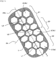
- Fig. 9 is a sectional view schematically showing a cross section perpendicular to a cell extending direction of another embodiment of the honeycomb structure of the present invention.
- Fig. 10 is an enlarged sectional view schematically showing a range shown in B of Fig. 9 .
- Fig. 11 is an enlarged sectional view schematically showing a range shown in C of Fig. 9 .
- Fig. 12 is an enlarged sectional view schematically showing a range shown in D of Fig. 9 .
- the honeycomb structure 100A includes a tubular honeycomb structure body 10A having porous partition walls 1 to define a plurality of cells 2 extending from a first end face 11 to a second end face 12. It is to be noted that in Fig. 9 to Fig. 12 , constitutional elements constituted similarly to the honeycomb structure 100 shown in Fig. 1 to Fig. 4 are denoted with the same reference numbers and description thereof may be omitted.
- the other line segments passing center of gravity O of the cross section and extending in a direction perpendicular to the partition walls 1 constituting the other sides other than the one side of each polygonal cell 2 are to be a second line segment 29b and a third line segment 29c, respectively.
- a sectional shape of the cells 2 formed in the honeycomb structure body 10A is hexagonal, and hence the number of the abovementioned "other line segments extending in the direction perpendicular to the partition walls 1" is two.
- the honeycomb structure body 10A of the honeycomb structure 100A shown in Fig. 9 is constituted so that a thickness of the partition walls 1 is relatively small in a central region 22 and a thickness of the partition walls 1 is relatively large in a circumferential region 21.
- the thicknesses of the partition walls 1 to define the respective cells 2 in the central region 22 and the circumferential region 21 are different from each other and are demarcated by a boundary 24. That is, the thickness of the partition walls 1 to define the central region cells 2a is relatively small and the thickness of the partition walls 1 to define the circumferential region cells 2b is relatively large.
- the plurality of cells 2 are arranged on the first line segment 29a, the second line segment 29b and the third line segment 29c in extending directions of the respective line segments.
- a cell pitch of the cells 2c becomes smaller.
- the cell pitch of the cells 2c becomes smaller.
- the cell pitch of the cells 2c becomes smaller.
- the cells 2c having a decreased cell pitch are referred to as small cell-pitch cells.
- the cells 2c having a decreased cell pitch are referred to as small cell-pitch cells.
- the small cell-pitch cells 2c having the decreased cell pitch are disposed, so that the thermal shock resistance of the boundary portion 23 can be enhanced.
- a cell pitch L2 of the small cell-pitch cells 2c preferably has a size of 70% or more and 95% or less to a cell pitch L1 of cells 2a arranged on the second line segment 29b in the central region 22.
- the cell pitch L2 of the small cell-pitch cells 2c preferably has a size of 70% or more and 95% or less to a cell pitch L3 of the cells 2b arranged on the second line segment 29b in the circumferential region 21.
- the cell pitch L2 of the small cell-pitch cells 2c preferably has a size of 70% or more and 95% or less to the cell pitch L1 of the cells 2a arranged on the third line segment 29c in the central region 22.
- the cell pitch L2 of the small cell-pitch cells 2c preferably has a size of 70% or more and 95% or less to the cell pitch L3 of the cells 2b arranged on the third line segment 29c in the circumferential region 21.
- a range in which the small cell-pitch cells 2c are disposed is, for example, on the first line segment 29a, a range in which the respective five or less cells 2c each arranged on the first line segment 29a toward each of the central region 22 and the circumferential region 21 from the boundary 24 are formed. That is, at most ten cells 2c in the boundary portion 23 between the central region 22 and the circumferential region 21 are the small cell-pitch cells 2c.
- the small cell-pitch cells 2c are constituted of one to ten cells each arranged on the first line segment 29a toward each of the central region 22 and the circumferential region 21 from the boundary 24.
- the small cell-pitch cells 2c are preferably constituted of two to nine cells each arranged on the line segment, and further preferably constituted of three to eight cells each arranged on the line segment.
- eleven cells or more arranged on the line segment are the small cell-pitch cells 2c
- heat stress generated during the temperature rise or drop of the honeycomb structure 100 concentrates on the boundary 24 between the central region 22 and the circumferential region 21 where the thickness of the partition walls 1 decreases, and larger thermal shock is disadvantageously applied to the boundary 24. Therefore, even when the small cell-pitch cells 2c are formed in a portion away from the boundary 24, the effect of improving the thermal shock resistance is not sufficiently exhibited.
- the sectional shape of the cells is hexagonal, but the cells may have a polygonal sectional shape other than the hexagonal sectional shape.
- a sectional shape of cells 32 is quadrangular.
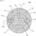
- Fig. 14 is a perspective view schematically showing a further embodiment of the honeycomb structure of the present invention.
- Fig. 15 is a plan view schematically showing a first end face of the further embodiment of the honeycomb structure of the present invention.
- Fig. 16 is an enlarged sectional view schematically showing a part of a cross section perpendicular to a cell extending direction of the further embodiment of the honeycomb structure of the present invention.
- the honeycomb structure 200 includes a tubular honeycomb structure body 40 having porous partition walls 31 to define the plurality of cells 32 extending from a first end face 41 to a second end face 42.
- the honeycomb structure body 40 has a circumferential wall 33 disposed at the outermost circumference so as to surround the partition walls 31.
- the honeycomb structure body 40 is constituted so that a thickness of the partition walls 31 in a circumferential region 51 positioned at an outer side of a central region 52 is larger than a thickness of the partition walls 31 in the central region 52 including a center of gravity O in a cross section perpendicular to an extending direction of the cells 32.
- one line segment passing the center of gravity O of the cross section and extending in a direction perpendicular to the partition walls 31 each constituting one side of each of the cells 32 is to be a first line segment 59a.
- first line segment 59a On the first line segment 59a, plurality of cells 32 are arranged in an extending direction of the first line segment 59a.
- the cells 32 present in the central region 52 are central region cells 32a.
- the cells 32 present in the circumferential region 51 are circumferential region cells 32b.
- Thicknesses of the partition walls 31 which define the respective cells 32 of the central region 52 and the circumferential region 51 are different from each other and are demarcated by a boundary 54. Furthermore, for respective five or less cells 32c each arranged on the first line segment 59a toward each of the central region 22 and the circumferential region 21 from the boundary 54 among the cells 32 arranged on the first line segment 59a, a cell pitch of the cells 32c is smaller as compared with the other cells 32. That is, a cell pitch L5 of the small cell-pitch cells 32c in the extending direction of the first line segment 59a has a size of 70% or more and 95% or less to a cell pitch L4 of the central region cells 32a.
- the cell pitch L5 of the small cell-pitch cells 32c in the extending direction of the first line segment 59a preferably has a size of 70% or more and 95% or less to a cell pitch L6 of the circumferential region cells 32b.
- the small cell-pitch cells 32c may be disposed on the second line segment. In this way, even for the honeycomb structure in which the sectional shape of the cells is quadrangular, there can be employed a constitution similar to that of the honeycomb structure in which the sectional shape of the cells is hexagonal as described hitherto.
- the small cell-pitch cells 32c have a quadrangular sectional shape whose two sides in the extending direction of the first line segment 59a are circularly curved.
- the small cell-pitch cells may have, for example, a quadrangular sectional shape in which at least one side of the sectional shape is curved, as long as the cell pitch L5 of the small cell-pitch cells 32c has a size of 70% or more and 95% or less to the cell pitch L4 of the central region cells 32a.
- a shape of the cells 32 (32a) formed in the central region 52 excluding the small cell-pitch cells 32c may be contracted in at least the extending direction of the first line segment 59a.
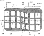
- Fig. 17 is an enlarged sectional view schematically showing a part of a cross section perpendicular to a cell extending direction of a further embodiment of the honeycomb structure of the present invention.
- constitutional elements constituted similarly to Fig. 16 are denoted with the same reference numbers and description thereof is omitted.
- a sectional shape of the small cell-pitch cells 32c is a parallelogram.
- a sectional shape of the central region cells 32a formed in the central region 52 is a square.
- the sectional shape of the central region cells 32a is contracted in the extending direction of the first line segment 59a, the sectional shape may be a quadrangular shape whose two sides are circularly curved as shown in Fig. 16 or a parallelogram as shown in Fig. 17 .
- a width at an open end in the extending direction of the first line segment 59a of each cell is smaller as compared with the central region cell 32a.
- the cell pitch L5 of the small cell-pitch cell 32c is smaller than the cell pitch L4 of the central region cell 32a (see Fig. 16 ).
- the honeycomb structure body 10 shown in Fig. 1 to Fig. 4 has the porous partition walls 1 and the circumferential wall 3 disposed at the outermost circumference so as to surround the partition walls 1.
- the circumferential wall 3 may be formed together with the partition walls 1 during extrusion of a honeycomb formed body in a process of preparing the honeycomb structure body 10. Furthermore, the circumferential wall 3 does not have to be formed during the extrusion.
- the circumferential wall 3 can be formed by applying a ceramic material to a circumferential portion of each of the partition walls 1 which define the cells 2.
- the circumferential wall 3 can be formed by grinding a circumferential portion of the honeycomb structure body 10 to remove the circumferential portion once and then applying the ceramic material so as to surround the partition walls 1.
- honeycomb structure body There is not any special restriction on a shape of the honeycomb structure body.
- the shape of the honeycomb structure body include a tubular shape in which end faces of the honeycomb structure body are circular (a cylindrical shape), a tubular shape whose end faces are oval, and a tubular shape whose end faces are polygonal.
- the polygonal shape include a quadrangular shape, a pentangular shape, a hexagonal shape, a heptagonal shape, and an octagonal shape.
- Fig. 1 to Fig. 4 show an example where the honeycomb structure body 10 has a tubular shape in which end faces are circular.
- the partition walls of the honeycomb structure body preferably include a ceramic material as a main component.
- An example of a material of the partition walls is preferably at least one selected from the following group. That is, the material is preferably at least one selected from the group consisting of silicon carbide, a silicon-silicon carbide based composite material, cordierite, mullite, alumina, spinel, a silicon carbide-cordierite based composite material, lithium aluminum silicate, and aluminum titanate.
- cordierite is preferable.
- main component means a component contained as much as 50 mass% or more in the material constituting the partition walls.
- the partition walls are made of a material including preferably 80 mass% or more and further preferably 90 mass% or more of at least one selected from the above group.
- a thickness of the partition walls is preferably from 40 to 400 ⁇ m, further preferably from 50 to 170 ⁇ m, and especially preferably from 50 to 120 ⁇ m.
- the honeycomb structure of the present embodiment is constituted so that the thickness of the partition walls is relatively small in the central region, and the thickness of the partition walls is relatively large in the circumferential region. Therefore, the thickness of the partition walls of the circumferential region is preferably from 1.05 to 1.8 times, further preferably from 1.05 to 1.6 times, and especially preferably from 1.05 to 1.4 times the thickness of the partition walls of the central region.
- the thickness of the partition walls in the circumferential region excluding a region where the small cell-pitch cells are formed among the cells arranged on the first line segment is preferably a thickness of 1.05 to 1.8 times the thickness of the partition walls in the central region excluding the region where the small cell-pitch cells are formed.
- “circumferential region” simply mentioned hereinafter means “circumferential region excluding the region where the small cell-pitch cells are formed”.
- central region simply mentioned hereinafter means “central region excluding the region where small cell-pitch cells are formed”.
- the thickness of the partition walls in the circumferential region is further preferably a thickness of 1.05 to 1.6 times and especially preferably a thickness of 1.05 to 1.4 times the thickness of the partition walls in the central region. Furthermore, the thickness of the partition walls in the boundary portion where the small cell-pitch cells are formed is preferably from 1.0 to 1.8 times the thickness of the partition walls in the central region where the boundary portion is present.
- a cell density of the honeycomb structure body is preferably from 30 to 150 cells/cm 2 .
- the cell density of the honeycomb structure body means the number of the cells per unit area in the cross section perpendicular to the extending direction of the cells.
- the cell density of the honeycomb structure body is further preferably from 60 to 150 cells/cm 2 and especially preferably from 90 to 150 cells/cm 2 . It is to be noted that in the honeycomb structure of the present embodiment, a value of the cell density of each of the central region and the circumferential region is different from that of the boundary portion where the small cell-pitch cells are formed. Furthermore, the cell densities of the central region and the circumferential region may have different values or the same value.
- the cell pitch of the cells formed in the central region and the cell pitch of the cells formed in the circumferential region may have the same size or different sizes.
- the cell pitch of the cells formed in the central region excluding the small cell-pitch cells may be smaller than that of the cells formed in the circumferential region excluding the small cell-pitch cells.
- a porosity of the partition walls is preferably from 20 to 60%, further preferably from 25 to 50%, and especially preferably from 25 to 40%.
- the porosity is smaller than 20%, the amount of the catalyst to be loaded in pores of the partition walls decreases in the case of the use of the honeycomb structure as a catalyst carrier, and characteristics concerning the loading of the catalyst onto the honeycomb structure may be deteriorated.
- the porosity is larger than 60%, the strength of the honeycomb structure body may be deteriorated.
- the porosity of the partition walls can be measured by a mercury porosimeter.
- An example of the mercury porosimeter is Autopore 9500 (trade name) manufactured by Micromeritics Co.
- a length from the first end face to the second end face of the honeycomb structure body is preferably from 50 to 170 mm and further preferably from 80 to 130 mm.
- the length from the first end face to the second end face of the honeycomb structure body is not limited to the above numerical value range, and may suitably be selected so as to obtain an optimum purification performance, when the honeycomb structure is used in each type of exhaust gas purification device.
- a size of the honeycomb structure body in a cross section perpendicular to an extending direction from the first end face to the second end face may suitably be selected so as to obtain the optimum purification performance when the honeycomb structure is used in each type of exhaust gas purification device. It is to be noted that when the shape of the cross section is circular in the honeycomb structure of the present embodiment, a diameter of this cross section is preferably from 70 to 170 mm and further preferably from 75 to 150 mm.
- a material of the circumferential wall may be the same as in the partition walls or may be different from that of the partition walls.
- the circumferential wall preferably includes at least one selected from the group consisting of silicon carbide, a silicon-silicon carbide based composite material, cordierite, mullite, alumina, spinel, a silicon carbide-cordierite based composite material, lithium aluminum silicate, and aluminum titanate. According to such a constitution, the honeycomb structure body excellent in thermal resistance is obtained.
- the honeycomb structure of the present embodiment may include plugging portions disposed in open ends of predetermined cells (first cells) in the first end face and open ends of residual cells (second cells) in the second end face.
- the first cells and the second cells are preferably alternately arranged.
- checkered patterns are preferably formed in both end faces of the honeycomb structure by the plugging portions and "the open ends of the cells".
- a material of the plugging portions is preferably a material which is considered to be preferable as the material of the partition walls.
- the material of the plugging portions and the material of the partition walls may be the same material or different materials.
- Such a honeycomb structure may suitably be used as a filter to trap a particulate matter in the exhaust gas.
- the catalyst may be loaded on the surfaces of the partition walls and the insides of the pores formed in the partition walls.
- the catalyst include various catalysts such as a ternary catalyst, a NO X storage reduction catalyst, an oxidation catalyst, and a NO X selective reduction catalyst including a metal-substituted zeolite as a main component.
- An example of a method of loading the catalyst onto the surfaces of the partition walls and the insides of the pores formed in the partition walls is a method in which heretofore known slurry for the catalyst is used.
- the slurry for the catalyst may contain a noble metal, a catalytic assistant, a noble metal holding material or the like in addition to the catalyst.
- the noble metal include platinum, rhodium and palladium.
- the catalytic assistant include alumina, zirconia and ceria.
- a manufacturing method of the honeycomb structure of the present invention will be described.
- a forming raw material containing a ceramic raw material is formed to obtain a tubular honeycomb formed body including partition walls (the partition walls prior to firing) to define the plurality of cells that become through channels for a fluid and a circumferential wall (the circumferential wall prior to the firing) positioned at the outermost circumference.
- the ceramic raw material to be contained in the forming raw material is preferably at least one selected from the following ceramic "raw material group".
- the "raw material group” is a "group consisting of silicon carbide, a silicon-silicon carbide composite material, a cordierite forming raw material, cordierite, mullite, alumina, spinel, a silicon carbide-cordierite composite material, lithium aluminum silicate, and aluminum titanate". These raw materials are used, so that it is possible to obtain the honeycomb structure excellent in strength and thermal resistance.
- the cordierite forming raw material is a ceramic raw material blended to obtain a chemical composition in which silica is in a range of 42 to 56 mass%, alumina is in a range of 30 to 45 mass%, and magnesia is in a range of 12 to 16 mass%, and the cordierite forming raw material is fired to become cordierite.
- a raw material component that becomes a silica source include quartz and molten silica.
- an alumina source component at least one of aluminum oxide and aluminum hydroxide is preferably used (both of the components may be used) because these components include less impurities.
- magnesia source component examples include talc and magnesite.
- talc an average particle diameter is preferably from 10 to 30 ⁇ m.
- the magnesia source component may contain Fe 2 O 3 , CaO, Na 2 O, K 2 O and the like as the impurities.
- the pore former examples include graphite, flour, starch, resin balloons, water absorbable polymer, and a "synthetic resin such as solid or hollow 'phenol resin, polymethyl methacrylate, polyethylene, or polyethylene terephthalate'".
- a content of the pore former is preferably from 1 to 10 mass%, when a content of the ceramic raw material is 100 mass%.
- surfactant examples include ethylene glycol and fatty acid soap.
- a content of the surfactant is preferably from 0.1 to 5 mass%, when the content of the ceramic raw material is 100 mass%.
- the die to form the honeycomb formed body it is preferable to use a die constituted so that a width of a slit of a portion corresponding to the central region of the honeycomb structure body to be obtained is relatively small and a width of a slit of a portion corresponding to the circumferential region is relatively large. Furthermore, during the extrusion, an extruding speed of the kneaded material to be extruded between the portion corresponding to the central region and the portion corresponding to the circumferential region is preferably relatively slow.
- the extruding speed of the kneaded material of a portion corresponding to the boundary portion where the small cell-pitch cells are formed is preferably slower than the extruding speed of the kneaded material of the portion corresponding to the central region and the circumferential region (and excluding the boundary portion).
- the boundary portion where the small cell-pitch cells are formed has a dented shape as compared with the central region and the circumferential region.
- the cell pitch of the cells formed in the above boundary portion becomes smaller as compared with the cell pitch of the cells formed in the central region and the circumferential region.
- the cell pitch of the small cell-pitch cells can be set to a size of 70% or more and 95% or less to the cell pitch of the other cells.
- An example of a method of adjusting the extruding speed of the kneaded material of the portion corresponding to the boundary portion where the small cell-pitch cells are formed is a method of closing a part of a back hole of a portion to be provided with a small cell pitch to the die. A part of the specific back hole is closed in this manner, whereby a flow of the kneaded material to a specific portion (i.e., the portion to be provided with the small cell pitch) can be slowed to partially lower the extruding speed.
- the die to form the honeycomb formed body there may be used a die in which a slit is beforehand formed so that the cell pitch of the cells of the boundary portion including the boundary between the central region and the circumferential region has a size of 70% or more and 95% or less to the cell pitch of the central region.
- an external force may be applied to the honeycomb formed body which is being extruded or the honeycomb formed body which is once extruded, to form the small cell-pitch cells in the boundary portion between the central region and the circumferential region.
- the small cell-pitch cells can be formed in the boundary portion between the central region and the circumferential region by its own weight of the honeycomb formed body. For a method of forming the small cell-pitch cells, various methods can be employed.
- the obtained honeycomb formed body is preferably dried.
- a drying method includes hot air drying, microwave drying, dielectric drying, reduced pressure drying, vacuum drying, and freeze drying.
- the dielectric drying, the microwave drying or the hot air drying is preferably performed alone, or any combination of these methods is preferably performed, because the whole honeycomb formed body can quickly and evenly be dried.
- drying conditions can suitably be determined in accordance with the drying method.
- the honeycomb structure is preferably obtained by firing the obtained honeycomb formed body (main firing).
- the "main firing” means an operation of sintering and densifying the forming raw material constituting the honeycomb formed body to provide a predetermined strength.
- the honeycomb formed body is preferably calcinated before the honeycomb formed body is fired (main firing).
- the calcinating is performed for degreasing.
- a burning temperature of the binder is from about 100 to 300°C
- a burning temperature of the pore former varies with a type of pore former, however is from about 200 to 1000°C. Therefore, as calcinating condition, heating is preferably performed at about 200 to 1000°C in an oxidation atmosphere for about three to 100 hours.
- Firing conditions (temperature and time) in the main firing vary with the type of forming raw material, and hence conditions may suitably be selected in accordance with the type of forming raw material.
- the firing highest temperature is preferably from 1410 to 1440°C.
- a firing highest temperature keeping (holding) time is preferably from three to 15 hours.
- honeycomb structure of the present invention can be manufactured as described above.
- the manufacturing method of the honeycomb structure of the present invention is not limited to the manufacturing method described hitherto.
- a kneaded material to form a honeycomb formed body was prepared by using a forming raw material containing a ceramic raw material.
- a cordierite forming raw material was used as the ceramic raw material.
- a dispersing medium, an organic binder, a dispersing agent and a pore former were added to the cordierite forming raw material to prepare the forming kneaded material.
- An amount of the dispersing medium to be added to 100 parts by mass of cordierite forming raw material was 33 parts by mass.
- An amount of the organic binder to be added to 100 parts by mass of cordierite forming raw material was 5.6 parts by mass.
- An amount of the pore former to be added to 100 parts by mass of cordierite forming raw material was 0.5 part by mass.
- the obtained first ceramic forming raw material was kneaded by using a kneader to obtain the kneaded material.
- the obtained kneaded material was extruded by using a vacuum extruder to obtain the honeycomb formed body.
- a die there was used a die in which a slit was formed so that a thickness of partition walls in a circumferential region positioned at an outer side of a central region was larger than a thickness of partition walls in the central region. Furthermore, for this die, there was used the die in which a sectional shape of cells of a honeycomb structure to be obtained was hexagonal.
- Table 1 shows "thickness ( ⁇ m) of the partition walls of the central region” and “thickness ( ⁇ m) of the partition walls of the circumferential region", "cell density (cells/cm 2 )", “sectional shape of the cells”, “diameter (mm) of the end face”, and “length (mm)” of the honeycomb structure to be obtained. Furthermore, as the die, there was used a die constituted so that a width of a slit of a portion corresponding to the central region of a honeycomb structure body to be obtained was relatively small and a width of a slit of a portion corresponding to the circumferential region was relatively large. Table 1 shows the thickness of the partition walls of the honeycomb structure to be obtained.
- Table 1 shows the "presence/absence” of the small cell-pitch cells and "arrangement direction of the small cell-pitch cells (direction of the line segment perpendicular to the partition walls)".
- Table 2 shows "number (cells) of the cells of the circumferential region", “cell pitch (mm) of the central region cells”, “range where the small cell-pitch cells are formed (number of the cells from the outermost circumference”, “cell pitch (minimum value) (mm) of the small cell-pitch cells”, and "ratio (%) of the cell pitch”.
- the ratio (%) of the cell pitch means a percentage (%) of the cell pitch (mm) of the small cell-pitch cells to the cell pitch (mm) of the central region cells.
- the thermal shock resistance (2) of the honeycomb structure was evaluated by a method similar to the "evaluation of the thermal shock resistance (1)" except that the flowing conditions as follows were regarded as one cycle and this operation was performed as much as 20 cycles.
- a combustion gas was allowed to flow at a flow rate of 60 NL/min. for ten minutes, and a gas temperature in a central portion at a position of 10 mm in front of the honeycomb structure was set to 1100°C after ten minutes.
- the combustion gas was stopped, cooling air was allowed to flow instead at a flow rate of 300 NL/min. for ten minutes, and a gas temperature in the central portion at the position of 10 mm in front of the honeycomb structure was set to 100°C after ten minutes.
- the number of the cells arranged on the first line segment from the outermost circumference of the cross section to the center of gravity of the cross section was 52.
- the number of the cells arranged from the center of gravity of the cross section in the 0° direction was 52.
- the cell positioned at the outermost circumference of the above cross section of the honeycomb structure of Example 1 is the first cell, and the cell positioned at the center of gravity of the cross section is the fifty-second cell.
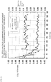
- Fig. 18 is a graph showing a relation between cell pitch (mm) of the cells arranged on the first line segment and thickness (mm) of the partition walls in the honeycomb structure of Example 1.
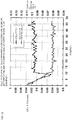
- Fig. 19 is a graph showing a relation between cell pitch (mm) of the cells arranged on the second line segment (i.e., the cells arranged in the 60° direction) and thickness (mm) of the partition walls in the honeycomb structure of Example 1.
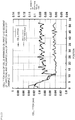
- Fig. 20 is a graph showing a relation between cell pitch (mm) of the cells arranged on the third line segment (i.e., the cells arranged in the 120° direction) and thickness (mm) of the partition walls in the honeycomb structure of Example 1. In the graphs shown in Fig. 18 to Fig.
- the abscissa indicates the positions of the cells in a case where the cell positioned in the outermost circumference of the cross section is the first cell and the cell positioned at the center of gravity of the cross section is the fifty-second cell.
- the right ordinate indicates the thickness (mm) of the partition walls
- the left ordinate indicates the cell pitch (mm).
- Thickness of partition walls of central region ⁇ m
- Thickness of partition walls of circumferential region ⁇ m
- Cell density cells/cm 2
- Example 2 The same procedures of Example 1 were repeated except that partition wall thickness, cell density, cell sectional shape, end face diameter, length, circumferential region forming range, central region forming range and small cell-pitch cell forming range were changed as shown in Table 1 and Table 2, to prepare the respective honeycomb structures.
- partition wall thickness, cell density, cell sectional shape, end face diameter, length, circumferential region forming range, central region forming range and small cell-pitch cell forming range were changed as shown in Table 1 and Table 2, to prepare the respective honeycomb structures.
- "evaluation of thermal shock resistance (1)” and “evaluation of thermal shock resistance (2)” were performed by a method similar to Example 1. The results are shown in Table 3.
- the sectional shape of the cells was quadrangular.
- the arrangement direction of the small cell-pitch cells was specified as follows.
- One line segment passing a center of gravity in a cross section perpendicular to a cell extending direction of the honeycomb structure and extending in a direction perpendicular to the partition walls each constituting one side of each quadrangular cell is to be a first line segment, and an extending direction of the first line segment is to be a "0° direction".
- a line segment obtained by rotating and moving the above one line segment as much as 90° in a clockwise direction based on the center of gravity of the cross section is to be a fourth line segment, and an extending direction of the fourth line segment is to be a "90° direction".
- Fig. 21 shows another example indicating a relation between cell pitch (mm) of cells arranged on a first line segment and thickness (mm) of partition walls.
- Fig. 21 is a graph showing the relation between the cell pitch (mm) of the cells arranged on the first line segment (i.e., the cells arranged in a 0° direction) and the thickness of the partition walls in a honeycomb structure of Example 13.
- the abscissa indicates positions of the cells in a case where the cell positioned at the outermost circumference of the cross section is the first cell and the cell positioned at the center of gravity of the cross section is the fifty-second cell.
- the right ordinate indicates the thickness (mm) of the partition walls
- the left ordinate indicates the cell pitch (mm).
- honeycomb structure of the present invention can be utilized in purification of an exhaust gas.
- the honeycomb structure of the present invention is usable in a catalyst carrier or a filter.
Landscapes
- Chemical & Material Sciences (AREA)
- Engineering & Computer Science (AREA)
- Chemical Kinetics & Catalysis (AREA)
- Physics & Mathematics (AREA)
- Geometry (AREA)
- Ceramic Engineering (AREA)
- General Engineering & Computer Science (AREA)
- Combustion & Propulsion (AREA)
- Mechanical Engineering (AREA)
- Toxicology (AREA)
- Health & Medical Sciences (AREA)
- Organic Chemistry (AREA)
- Structural Engineering (AREA)
- Materials Engineering (AREA)
- Catalysts (AREA)
- Filtering Of Dispersed Particles In Gases (AREA)
- Filtering Materials (AREA)
- Exhaust Gas Treatment By Means Of Catalyst (AREA)
- Exhaust Gas After Treatment (AREA)
- Processes For Solid Components From Exhaust (AREA)
- Disinfection, Sterilisation Or Deodorisation Of Air (AREA)
Claims (5)
- Wabenstruktur (100), umfassend:einen rohrförmigen Wabenstrukturkörper (10), welcher poröse Trennwände (1) aufweist, um eine Vielzahl von Zellen (2) zu definieren, welche sich von einer ersten Endfläche (11) zu einer zweiten Endfläche (12) erstrecken,worin die Trennwände (1) in einem Querschnitt senkrecht auf eine Erstreckungsrichtung der Zellen (2) des Wabenstrukturkörpers (10) so angeordnet sind, dass eine Form der Zellen (2) vieleckig ist, undder Wabenstrukturkörper (10) so gebildet ist, dass eine Dicke der Trennwände (1) in einer Umfangsregion (21), welche auf einer Außenseite einer zentralen Region (22) angeordnet ist, größer ist als eine Dicke der Trennwände (1) in der zentralen Region (22), welche einen Schwerpunkt (0) des Querschnitts umfasst;dadurch gekennzeichnet, dass
im Querschnitt des Wabenstrukturkörpers (10), wenn ein Liniensegment, das den Schwerpunkt (0) des Querschnitts durchläuft und sich in eine Richtung senkrecht auf die Trennwände (1) erstreckt, die jeweils eine Seite von jeder der vieleckigen Zellen (2) bilden, ein erstes Liniensegment (29a) ist, für eine bis zu fünf jeweilige Zellen mit kleiner Zellenbreite (2c), die unter den auf dem ersten Liniensegment (29a) angeordneten Zellen von einer Grenze (24) zwischen der zentralen Region (22) und der Umfangsregion (21) hin zu jeder der zentralen Region (22) und der Umfangsregion (21) auf dem ersten Liniensegment angeordnet sind, eine Zellenbreite (L2) der Zellen mit kleiner Zellenbreite (2c) in einer Erstreckungsrichtung des ersten Liniensegments (29a) eine Größe von 70 % oder mehr und 95 % oder weniger der Zellenbreite (L1) von Zellen in der zentralen Region (2a) aufweist, wobei die eine bis zu fünf jeweiligen Zellen mit kleiner Zellenbreite (2c) von den Zellen in der zentralen Region (2a) ausgenommen sind, wobei die Zellenbreite (L1) der Zellen in der zentralen Region (2a) in der Erstreckungsrichtung des ersten Liniensegments (29a) bestimmt wird. - Wabenstruktur nach Anspruch 1, worin im Querschnitt des Wabenstrukturkörpers (10), wenn ein anderes Liniensegment, welches den Schwerpunkt (0) des Querschnitts durchläuft und sich in eine Richtung senkrecht auf die Trennwände (1), die andere Seiten als die eine Seite von jeder der vieleckigen Zellen (2) bilden, erstreckt, ein zweites Liniensegment (29b) ist, für eine bis zu fünf jeweilige Zellen mit kleiner Zellbreite (2c), die unter den auf dem zweiten Liniensegment (29b) angeordneten Zellen von der Grenze (24) zwischen der zentralen Region und der Umfangsregion hin zu jeder der zentralen Region (22) und der Umfangsregion (21) auf dem zweiten Liniensegment angeordnet sind, eine Zellenbreite (L2) der Zellen mit kleiner Zellenbreite (2c) in der Erstreckungsrichtung des zweiten Liniensegments (29b) eine Größe von 70 % oder mehr und 95 % oder weniger einer Zellenbreite (L1) von Zellen in der zentralen Region (2a) aufweist, wobei die eine bis zu fünf jeweiligen Zellen mit kleiner Zellenbreite (2c) von den Zellen in der zentralen Region (2a) ausgenommen sind, wobei die Zellenbreite (L1) der Zellen in der zentralen Region (2a) in der Erstreckungsrichtung des zweiten Liniensegments (29b) bestimmt wird.
- Wabenstruktur nach Anspruch 1 oder 2, worin in den auf dem ersten Liniensegment (29a) angeordneten Zellen eine Form der einen bis zu fünf jeweiligen Zellen mit kleiner Zellenbreite (2c), die jeweils von der Grenze (24) zwischen der zentralen Region (22) und der Umfangsregion (21) hin zu jeder der zentralen Region (22) und der Umfangsregion (21) auf dem ersten Liniensegment (29a) angeordnet sind, eine Form ist, die durch Kontraktion einer Form der Zellen in der zentralen Region (2a) mit Ausnahme der einen bis zu fünf jeweiligen Zellen mit kleiner Zellenbreite (2c) in zumindest der Erstreckungsrichtung des ersten Liniensegments (29a) erhalten wird.
- Wabenstruktur nach einem der Ansprüche 1 bis 3,
worin bei den auf dem ersten Liniensegment (29a) angeordneten Zellen eine Dicke der Trennwände (1) in der Umfangsregion (21) mit Ausnahme der einen bis zu fünf jeweiligen Zellen mit kleiner Zellenbreite (2c), welche in der Erstreckungsrichten der ersten Liniensegments (29a) angeordnet sind, 1,05 bis 1,8 Mal eine Dicke der Trennwände (1) in der zentralen Region (22) mit Ausnahme der einen bis fünf jeweiligen Zellen mit kleiner Zellenbreite (2c) ist, die in der Erstreckungsrichtung des ersten Liniensegments (29a) in der zentralen Region (22) angeordnet sind. - Wabenstruktur nach einem der Ansprüche 1 bis 4,
worin bei den auf dem ersten Liniensegment (29a) angeordneten Zellen eine Zellenbreite (L1) der Zellen in der zentralen Region (2a) mit Ausnahme der einen bis zu fünf jeweiligen Zellen mit geringer Zellenbreite (2c), die in der Erstreckungsrichtung des ersten Liniensegments (29a) angeordnet sind, dieselbe Zellenbreite (L3) aufweist wie die der in der Umfangsregion (21) ausgebildeten Umfangsregionszellen (2b) mit Ausnahme der einen bis zu fünf jeweiligen Zellen mit kleiner Zellenbreite (2c), welche in der Erstreckungsrichtung des ersten Liniensegments (29a) angeordnet sind.
Applications Claiming Priority (1)
| Application Number | Priority Date | Filing Date | Title |
|---|---|---|---|
| JP2013200251 | 2013-09-26 |
Publications (2)
| Publication Number | Publication Date |
|---|---|
| EP2853708A1 EP2853708A1 (de) | 2015-04-01 |
| EP2853708B1 true EP2853708B1 (de) | 2017-02-22 |
Family
ID=51626398
Family Applications (1)
| Application Number | Title | Priority Date | Filing Date |
|---|---|---|---|
| EP14186312.6A Active EP2853708B1 (de) | 2013-09-26 | 2014-09-25 | Wabenstruktur |
Country Status (4)
| Country | Link |
|---|---|
| US (1) | US9663408B2 (de) |
| EP (1) | EP2853708B1 (de) |
| JP (1) | JP6339463B2 (de) |
| CN (1) | CN204200312U (de) |
Families Citing this family (15)
| Publication number | Priority date | Publication date | Assignee | Title |
|---|---|---|---|---|
| JP6581926B2 (ja) * | 2016-03-07 | 2019-09-25 | 日本碍子株式会社 | ハニカム構造体 |
| JP6742779B2 (ja) * | 2016-03-30 | 2020-08-19 | 日本碍子株式会社 | 還元剤噴射装置、及び排ガス処理装置 |
| MX2018011403A (es) | 2016-03-31 | 2019-02-20 | Ngk Insulators Ltd | Estructura de membrana de separacion monolitica. |
| US10323532B2 (en) * | 2016-05-19 | 2019-06-18 | General Electric Company | Flow discourager and method of making same |
| JP6247343B2 (ja) * | 2016-06-10 | 2017-12-13 | 日本碍子株式会社 | ハニカム構造体 |
| JP6620082B2 (ja) * | 2016-12-15 | 2019-12-11 | 日本碍子株式会社 | ハニカム構造体の製造方法 |
| TWI622252B (zh) * | 2016-12-16 | 2018-04-21 | 財團法人工業技術研究院 | 具有散熱功能之馬達轉軸系統 |
| JP6779195B2 (ja) * | 2017-11-16 | 2020-11-04 | 日本碍子株式会社 | ハニカム構造体 |
| SE543870C2 (en) * | 2018-01-24 | 2021-08-17 | Husqvarna Ab | Leaf blower |
| JP6881337B2 (ja) * | 2018-01-30 | 2021-06-02 | 株式会社デンソー | ハニカム構造体および金型 |
| JP7069753B6 (ja) * | 2018-01-30 | 2023-12-20 | 株式会社デンソー | ハニカム構造体 |
| JP7003694B2 (ja) * | 2018-01-30 | 2022-01-20 | 株式会社デンソー | ハニカム構造体 |
| JP7035567B2 (ja) * | 2018-01-30 | 2022-03-15 | 株式会社デンソー | ハニカム構造体および金型 |
| USD894361S1 (en) * | 2018-02-20 | 2020-08-25 | Ngk Insulators, Ltd. | Catalyst carrier for exhaust gas purification |
| WO2023101819A1 (en) * | 2021-11-30 | 2023-06-08 | Corning Incorporated | Methods and extrusion dies for manufacturing ceramic honeycomb bodies with peripheral strengthening |
Family Cites Families (12)
| Publication number | Priority date | Publication date | Assignee | Title |
|---|---|---|---|---|
| JPS55155742A (en) * | 1979-05-22 | 1980-12-04 | Ngk Spark Plug Co Ltd | High strength honeycomb structure |
| JP4159155B2 (ja) * | 1998-01-22 | 2008-10-01 | 株式会社日本自動車部品総合研究所 | セラミックハニカム構造体および押出金型 |
| JP3126697B2 (ja) | 1998-03-31 | 2001-01-22 | 日本碍子株式会社 | 高強度薄壁ハニカム構造体 |
| JP3229595B2 (ja) | 1998-12-18 | 2001-11-19 | 日本碍子株式会社 | 排ガス浄化装置 |
| JP4234836B2 (ja) | 1999-02-18 | 2009-03-04 | 日本碍子株式会社 | ハニカム構造体及びその複合体 |
| WO2002011884A1 (fr) | 2000-08-03 | 2002-02-14 | Ngk Insulators, Ltd. | Structure céramique alvéolaire |
| JP5052717B2 (ja) * | 2001-05-02 | 2012-10-17 | 日本碍子株式会社 | ハニカム構造体、及びそれを用いたハニカムフィルター、コンバーターシステム |
| DE60336824D1 (de) * | 2002-09-05 | 2011-06-01 | Ngk Insulators Ltd | Wabenstruktur |
| WO2009141885A1 (ja) | 2008-05-20 | 2009-11-26 | イビデン株式会社 | ハニカム構造体 |
| US8556615B2 (en) * | 2009-03-27 | 2013-10-15 | Ngk Insulators, Ltd. | Die for forming honeycomb structure and manufacturing method of the same |
| JP5639343B2 (ja) | 2009-03-31 | 2014-12-10 | 日本碍子株式会社 | ハニカム触媒体 |
| JP5409465B2 (ja) * | 2010-03-23 | 2014-02-05 | 日本碍子株式会社 | ハニカム構造体 |
-
2014
- 2014-09-22 US US14/492,772 patent/US9663408B2/en active Active
- 2014-09-24 JP JP2014193609A patent/JP6339463B2/ja active Active
- 2014-09-25 CN CN201420556126.2U patent/CN204200312U/zh active Active
- 2014-09-25 EP EP14186312.6A patent/EP2853708B1/de active Active
Non-Patent Citations (1)
| Title |
|---|
| None * |
Also Published As
| Publication number | Publication date |
|---|---|
| CN204200312U (zh) | 2015-03-11 |
| EP2853708A1 (de) | 2015-04-01 |
| US9663408B2 (en) | 2017-05-30 |
| US20150086748A1 (en) | 2015-03-26 |
| JP6339463B2 (ja) | 2018-06-06 |
| JP2015085321A (ja) | 2015-05-07 |
Similar Documents
| Publication | Publication Date | Title |
|---|---|---|
| EP2853708B1 (de) | Wabenstruktur | |
| EP2343113B1 (de) | Bienenwabenstruktur | |
| EP2425888B1 (de) | Wabenstrukturkörper | |
| JP5144075B2 (ja) | ハニカム構造体及びその製造方法 | |
| EP2380649B1 (de) | Abgasreinigungsvorrichtung | |
| EP2364764B1 (de) | Abgasreinigungsvorrichtung und Abgasreinigungsverfahren | |
| US9340463B2 (en) | Honeycomb structure | |
| EP2604323A1 (de) | Wabenfilter und herstellungsverfahren dafür | |
| JP5997026B2 (ja) | ハニカム触媒体 | |
| US9447716B2 (en) | Honeycomb structure | |
| JP5601957B2 (ja) | チタン酸アルミニウム質ハニカム構造体 | |
| EP2784043A2 (de) | Verfahren zur Herstellung einer Wabenstruktur und Wabenstruktur | |
| EP2698191A1 (de) | Abgedichtete Wabenstruktur | |
| EP2500079B1 (de) | Wabenstruktur | |
| EP2371441B1 (de) | Abgasreinigungsvorrichtung | |
| JP6824770B2 (ja) | ハニカム構造体 | |
| CN113272042B (zh) | 含堇青石的陶瓷体、批料组合物混合物和含堇青石的陶瓷体的制造方法 | |
| JP6110750B2 (ja) | 目封止ハニカム構造体 | |
| JP5345371B2 (ja) | ハニカム構造体の製造方法 | |
| JPWO2005068396A1 (ja) | ハニカム構造体及びその製造方法 | |
| EP2221099B1 (de) | Wabenstruktur | |
| JP2021535068A (ja) | コーディエライト‐インディアライト‐擬板チタン石構造セラミック体、バッチ組成物混合物、及びこれらからセラミック体を製造する方法 | |
| EP2915791A2 (de) | Wabenstruktur | |
| US11046621B2 (en) | Honeycomb structure | |
| CN219672708U (zh) | 蜂窝过滤器 |
Legal Events
| Date | Code | Title | Description |
|---|---|---|---|
| PUAI | Public reference made under article 153(3) epc to a published international application that has entered the european phase |
Free format text: ORIGINAL CODE: 0009012 |
|
| 17P | Request for examination filed |
Effective date: 20140925 |
|
| AK | Designated contracting states |
Kind code of ref document: A1 Designated state(s): AL AT BE BG CH CY CZ DE DK EE ES FI FR GB GR HR HU IE IS IT LI LT LU LV MC MK MT NL NO PL PT RO RS SE SI SK SM TR |
|
| AX | Request for extension of the european patent |
Extension state: BA ME |
|
| R17P | Request for examination filed (corrected) |
Effective date: 20150930 |
|
| RBV | Designated contracting states (corrected) |
Designated state(s): AL AT BE BG CH CY CZ DE DK EE ES FI FR GB GR HR HU IE IS IT LI LT LU LV MC MK MT NL NO PL PT RO RS SE SI SK SM TR |
|
| 17Q | First examination report despatched |
Effective date: 20160226 |
|
| REG | Reference to a national code |
Ref country code: DE Ref legal event code: R079 Ref document number: 602014006878 Country of ref document: DE Free format text: PREVIOUS MAIN CLASS: F01N0003280000 Ipc: C04B0038000000 |
|
| RIC1 | Information provided on ipc code assigned before grant |
Ipc: C04B 38/00 20060101AFI20160707BHEP Ipc: F01N 3/28 20060101ALI20160707BHEP Ipc: F01N 3/022 20060101ALI20160707BHEP Ipc: B01D 46/24 20060101ALI20160707BHEP |
|
| GRAP | Despatch of communication of intention to grant a patent |
Free format text: ORIGINAL CODE: EPIDOSNIGR1 |
|
| INTG | Intention to grant announced |
Effective date: 20160928 |
|
| GRAS | Grant fee paid |
Free format text: ORIGINAL CODE: EPIDOSNIGR3 |
|
| GRAA | (expected) grant |
Free format text: ORIGINAL CODE: 0009210 |
|
| AK | Designated contracting states |
Kind code of ref document: B1 Designated state(s): AL AT BE BG CH CY CZ DE DK EE ES FI FR GB GR HR HU IE IS IT LI LT LU LV MC MK MT NL NO PL PT RO RS SE SI SK SM TR |
|
| REG | Reference to a national code |
Ref country code: GB Ref legal event code: FG4D |
|
| REG | Reference to a national code |
Ref country code: CH Ref legal event code: EP |
|
| REG | Reference to a national code |
Ref country code: AT Ref legal event code: REF Ref document number: 869126 Country of ref document: AT Kind code of ref document: T Effective date: 20170315 |
|
| REG | Reference to a national code |
Ref country code: IE Ref legal event code: FG4D |
|
| REG | Reference to a national code |
Ref country code: DE Ref legal event code: R096 Ref document number: 602014006878 Country of ref document: DE |
|
| REG | Reference to a national code |
Ref country code: LT Ref legal event code: MG4D |
|
| REG | Reference to a national code |
Ref country code: NL Ref legal event code: MP Effective date: 20170222 |
|
| REG | Reference to a national code |
Ref country code: AT Ref legal event code: MK05 Ref document number: 869126 Country of ref document: AT Kind code of ref document: T Effective date: 20170222 |
|
| PG25 | Lapsed in a contracting state [announced via postgrant information from national office to epo] |
Ref country code: FI Free format text: LAPSE BECAUSE OF FAILURE TO SUBMIT A TRANSLATION OF THE DESCRIPTION OR TO PAY THE FEE WITHIN THE PRESCRIBED TIME-LIMIT Effective date: 20170222 Ref country code: NO Free format text: LAPSE BECAUSE OF FAILURE TO SUBMIT A TRANSLATION OF THE DESCRIPTION OR TO PAY THE FEE WITHIN THE PRESCRIBED TIME-LIMIT Effective date: 20170522 Ref country code: LT Free format text: LAPSE BECAUSE OF FAILURE TO SUBMIT A TRANSLATION OF THE DESCRIPTION OR TO PAY THE FEE WITHIN THE PRESCRIBED TIME-LIMIT Effective date: 20170222 Ref country code: HR Free format text: LAPSE BECAUSE OF FAILURE TO SUBMIT A TRANSLATION OF THE DESCRIPTION OR TO PAY THE FEE WITHIN THE PRESCRIBED TIME-LIMIT Effective date: 20170222 Ref country code: GR Free format text: LAPSE BECAUSE OF FAILURE TO SUBMIT A TRANSLATION OF THE DESCRIPTION OR TO PAY THE FEE WITHIN THE PRESCRIBED TIME-LIMIT Effective date: 20170523 |
|
| REG | Reference to a national code |
Ref country code: FR Ref legal event code: PLFP Year of fee payment: 4 |
|
| PG25 | Lapsed in a contracting state [announced via postgrant information from national office to epo] |
Ref country code: SE Free format text: LAPSE BECAUSE OF FAILURE TO SUBMIT A TRANSLATION OF THE DESCRIPTION OR TO PAY THE FEE WITHIN THE PRESCRIBED TIME-LIMIT Effective date: 20170222 Ref country code: NL Free format text: LAPSE BECAUSE OF FAILURE TO SUBMIT A TRANSLATION OF THE DESCRIPTION OR TO PAY THE FEE WITHIN THE PRESCRIBED TIME-LIMIT Effective date: 20170222 Ref country code: RS Free format text: LAPSE BECAUSE OF FAILURE TO SUBMIT A TRANSLATION OF THE DESCRIPTION OR TO PAY THE FEE WITHIN THE PRESCRIBED TIME-LIMIT Effective date: 20170222 Ref country code: ES Free format text: LAPSE BECAUSE OF FAILURE TO SUBMIT A TRANSLATION OF THE DESCRIPTION OR TO PAY THE FEE WITHIN THE PRESCRIBED TIME-LIMIT Effective date: 20170222 Ref country code: BG Free format text: LAPSE BECAUSE OF FAILURE TO SUBMIT A TRANSLATION OF THE DESCRIPTION OR TO PAY THE FEE WITHIN THE PRESCRIBED TIME-LIMIT Effective date: 20170522 Ref country code: PT Free format text: LAPSE BECAUSE OF FAILURE TO SUBMIT A TRANSLATION OF THE DESCRIPTION OR TO PAY THE FEE WITHIN THE PRESCRIBED TIME-LIMIT Effective date: 20170622 Ref country code: AT Free format text: LAPSE BECAUSE OF FAILURE TO SUBMIT A TRANSLATION OF THE DESCRIPTION OR TO PAY THE FEE WITHIN THE PRESCRIBED TIME-LIMIT Effective date: 20170222 Ref country code: LV Free format text: LAPSE BECAUSE OF FAILURE TO SUBMIT A TRANSLATION OF THE DESCRIPTION OR TO PAY THE FEE WITHIN THE PRESCRIBED TIME-LIMIT Effective date: 20170222 |
|
| PG25 | Lapsed in a contracting state [announced via postgrant information from national office to epo] |
Ref country code: RO Free format text: LAPSE BECAUSE OF FAILURE TO SUBMIT A TRANSLATION OF THE DESCRIPTION OR TO PAY THE FEE WITHIN THE PRESCRIBED TIME-LIMIT Effective date: 20170222 Ref country code: EE Free format text: LAPSE BECAUSE OF FAILURE TO SUBMIT A TRANSLATION OF THE DESCRIPTION OR TO PAY THE FEE WITHIN THE PRESCRIBED TIME-LIMIT Effective date: 20170222 Ref country code: IT Free format text: LAPSE BECAUSE OF FAILURE TO SUBMIT A TRANSLATION OF THE DESCRIPTION OR TO PAY THE FEE WITHIN THE PRESCRIBED TIME-LIMIT Effective date: 20170222 Ref country code: CZ Free format text: LAPSE BECAUSE OF FAILURE TO SUBMIT A TRANSLATION OF THE DESCRIPTION OR TO PAY THE FEE WITHIN THE PRESCRIBED TIME-LIMIT Effective date: 20170222 Ref country code: SK Free format text: LAPSE BECAUSE OF FAILURE TO SUBMIT A TRANSLATION OF THE DESCRIPTION OR TO PAY THE FEE WITHIN THE PRESCRIBED TIME-LIMIT Effective date: 20170222 |
|
| REG | Reference to a national code |
Ref country code: DE Ref legal event code: R097 Ref document number: 602014006878 Country of ref document: DE |
|
| PG25 | Lapsed in a contracting state [announced via postgrant information from national office to epo] |
Ref country code: SM Free format text: LAPSE BECAUSE OF FAILURE TO SUBMIT A TRANSLATION OF THE DESCRIPTION OR TO PAY THE FEE WITHIN THE PRESCRIBED TIME-LIMIT Effective date: 20170222 Ref country code: PL Free format text: LAPSE BECAUSE OF FAILURE TO SUBMIT A TRANSLATION OF THE DESCRIPTION OR TO PAY THE FEE WITHIN THE PRESCRIBED TIME-LIMIT Effective date: 20170222 Ref country code: DK Free format text: LAPSE BECAUSE OF FAILURE TO SUBMIT A TRANSLATION OF THE DESCRIPTION OR TO PAY THE FEE WITHIN THE PRESCRIBED TIME-LIMIT Effective date: 20170222 |
|
| PLBE | No opposition filed within time limit |
Free format text: ORIGINAL CODE: 0009261 |
|
| STAA | Information on the status of an ep patent application or granted ep patent |
Free format text: STATUS: NO OPPOSITION FILED WITHIN TIME LIMIT |
|
| 26N | No opposition filed |
Effective date: 20171123 |
|
| PG25 | Lapsed in a contracting state [announced via postgrant information from national office to epo] |
Ref country code: SI Free format text: LAPSE BECAUSE OF FAILURE TO SUBMIT A TRANSLATION OF THE DESCRIPTION OR TO PAY THE FEE WITHIN THE PRESCRIBED TIME-LIMIT Effective date: 20170222 |
|
| REG | Reference to a national code |
Ref country code: CH Ref legal event code: PL |
|
| PG25 | Lapsed in a contracting state [announced via postgrant information from national office to epo] |
Ref country code: MC Free format text: LAPSE BECAUSE OF FAILURE TO SUBMIT A TRANSLATION OF THE DESCRIPTION OR TO PAY THE FEE WITHIN THE PRESCRIBED TIME-LIMIT Effective date: 20170222 |
|
| REG | Reference to a national code |
Ref country code: IE Ref legal event code: MM4A |
|
| REG | Reference to a national code |
Ref country code: BE Ref legal event code: MM Effective date: 20170930 |
|
| PG25 | Lapsed in a contracting state [announced via postgrant information from national office to epo] |
Ref country code: LU Free format text: LAPSE BECAUSE OF NON-PAYMENT OF DUE FEES Effective date: 20170925 |
|
| PG25 | Lapsed in a contracting state [announced via postgrant information from national office to epo] |
Ref country code: LI Free format text: LAPSE BECAUSE OF NON-PAYMENT OF DUE FEES Effective date: 20170930 Ref country code: CH Free format text: LAPSE BECAUSE OF NON-PAYMENT OF DUE FEES Effective date: 20170930 Ref country code: IE Free format text: LAPSE BECAUSE OF NON-PAYMENT OF DUE FEES Effective date: 20170925 |
|
| REG | Reference to a national code |
Ref country code: FR Ref legal event code: PLFP Year of fee payment: 5 |
|
| PG25 | Lapsed in a contracting state [announced via postgrant information from national office to epo] |
Ref country code: BE Free format text: LAPSE BECAUSE OF NON-PAYMENT OF DUE FEES Effective date: 20170930 |
|
| PG25 | Lapsed in a contracting state [announced via postgrant information from national office to epo] |
Ref country code: MT Free format text: LAPSE BECAUSE OF NON-PAYMENT OF DUE FEES Effective date: 20170925 |
|
| GBPC | Gb: european patent ceased through non-payment of renewal fee |
Effective date: 20180925 |
|
| PG25 | Lapsed in a contracting state [announced via postgrant information from national office to epo] |
Ref country code: HU Free format text: LAPSE BECAUSE OF FAILURE TO SUBMIT A TRANSLATION OF THE DESCRIPTION OR TO PAY THE FEE WITHIN THE PRESCRIBED TIME-LIMIT; INVALID AB INITIO Effective date: 20140925 |
|
| PG25 | Lapsed in a contracting state [announced via postgrant information from national office to epo] |
Ref country code: GB Free format text: LAPSE BECAUSE OF NON-PAYMENT OF DUE FEES Effective date: 20180925 Ref country code: CY Free format text: LAPSE BECAUSE OF FAILURE TO SUBMIT A TRANSLATION OF THE DESCRIPTION OR TO PAY THE FEE WITHIN THE PRESCRIBED TIME-LIMIT Effective date: 20170222 |
|
| PG25 | Lapsed in a contracting state [announced via postgrant information from national office to epo] |
Ref country code: MK Free format text: LAPSE BECAUSE OF FAILURE TO SUBMIT A TRANSLATION OF THE DESCRIPTION OR TO PAY THE FEE WITHIN THE PRESCRIBED TIME-LIMIT Effective date: 20170222 |
|
| PG25 | Lapsed in a contracting state [announced via postgrant information from national office to epo] |
Ref country code: TR Free format text: LAPSE BECAUSE OF FAILURE TO SUBMIT A TRANSLATION OF THE DESCRIPTION OR TO PAY THE FEE WITHIN THE PRESCRIBED TIME-LIMIT Effective date: 20170222 |
|
| PG25 | Lapsed in a contracting state [announced via postgrant information from national office to epo] |
Ref country code: AL Free format text: LAPSE BECAUSE OF FAILURE TO SUBMIT A TRANSLATION OF THE DESCRIPTION OR TO PAY THE FEE WITHIN THE PRESCRIBED TIME-LIMIT Effective date: 20170222 Ref country code: IS Free format text: LAPSE BECAUSE OF FAILURE TO SUBMIT A TRANSLATION OF THE DESCRIPTION OR TO PAY THE FEE WITHIN THE PRESCRIBED TIME-LIMIT Effective date: 20170622 |
|
| PGFP | Annual fee paid to national office [announced via postgrant information from national office to epo] |
Ref country code: FR Payment date: 20230808 Year of fee payment: 10 Ref country code: DE Payment date: 20230802 Year of fee payment: 10 |