EP2423524A1 - Palier de butée à rouleaux et procédé de fabrication de bague de roulement de butée - Google Patents
Palier de butée à rouleaux et procédé de fabrication de bague de roulement de butée Download PDFInfo
- Publication number
- EP2423524A1 EP2423524A1 EP10766898A EP10766898A EP2423524A1 EP 2423524 A1 EP2423524 A1 EP 2423524A1 EP 10766898 A EP10766898 A EP 10766898A EP 10766898 A EP10766898 A EP 10766898A EP 2423524 A1 EP2423524 A1 EP 2423524A1
- Authority
- EP
- European Patent Office
- Prior art keywords
- race
- thrust
- cylindrical portion
- roller bearing
- protrusions
- Prior art date
- Legal status (The legal status is an assumption and is not a legal conclusion. Google has not performed a legal analysis and makes no representation as to the accuracy of the status listed.)
- Granted
Links
- 238000004519 manufacturing process Methods 0.000 title claims abstract description 27
- 230000013011 mating Effects 0.000 claims abstract description 26
- 229910052751 metal Inorganic materials 0.000 claims description 53
- 239000002184 metal Substances 0.000 claims description 53
- 238000005096 rolling process Methods 0.000 claims description 17
- 238000005452 bending Methods 0.000 claims description 13
- 238000000034 method Methods 0.000 claims description 11
- 230000004323 axial length Effects 0.000 claims description 4
- 238000005520 cutting process Methods 0.000 claims description 4
- 230000005540 biological transmission Effects 0.000 description 6
- 230000003449 preventive effect Effects 0.000 description 4
- 238000000926 separation method Methods 0.000 description 4
- 239000010687 lubricating oil Substances 0.000 description 3
- 239000000463 material Substances 0.000 description 3
- 238000003825 pressing Methods 0.000 description 3
- 229910000975 Carbon steel Inorganic materials 0.000 description 2
- 229910000831 Steel Inorganic materials 0.000 description 2
- 239000010962 carbon steel Substances 0.000 description 2
- 230000000694 effects Effects 0.000 description 2
- 230000002265 prevention Effects 0.000 description 2
- 239000010959 steel Substances 0.000 description 2
- 229910000838 Al alloy Inorganic materials 0.000 description 1
- 229910000760 Hardened steel Inorganic materials 0.000 description 1
- 230000002159 abnormal effect Effects 0.000 description 1
- 238000005299 abrasion Methods 0.000 description 1
- 229910052782 aluminium Inorganic materials 0.000 description 1
- XAGFODPZIPBFFR-UHFFFAOYSA-N aluminium Chemical compound [Al] XAGFODPZIPBFFR-UHFFFAOYSA-N 0.000 description 1
- 238000013459 approach Methods 0.000 description 1
- 230000015572 biosynthetic process Effects 0.000 description 1
- 230000007423 decrease Effects 0.000 description 1
- 238000010586 diagram Methods 0.000 description 1
- 239000012530 fluid Substances 0.000 description 1
- 239000000446 fuel Substances 0.000 description 1
- 239000007788 liquid Substances 0.000 description 1
- 238000005461 lubrication Methods 0.000 description 1
- 238000012423 maintenance Methods 0.000 description 1
- 238000012986 modification Methods 0.000 description 1
- 230000004048 modification Effects 0.000 description 1
- 238000006748 scratching Methods 0.000 description 1
- 230000002393 scratching effect Effects 0.000 description 1
- 239000007779 soft material Substances 0.000 description 1
Images


Classifications
-
- F—MECHANICAL ENGINEERING; LIGHTING; HEATING; WEAPONS; BLASTING
- F16—ENGINEERING ELEMENTS AND UNITS; GENERAL MEASURES FOR PRODUCING AND MAINTAINING EFFECTIVE FUNCTIONING OF MACHINES OR INSTALLATIONS; THERMAL INSULATION IN GENERAL
- F16C—SHAFTS; FLEXIBLE SHAFTS; ELEMENTS OR CRANKSHAFT MECHANISMS; ROTARY BODIES OTHER THAN GEARING ELEMENTS; BEARINGS
- F16C19/00—Bearings with rolling contact, for exclusively rotary movement
- F16C19/22—Bearings with rolling contact, for exclusively rotary movement with bearing rollers essentially of the same size in one or more circular rows, e.g. needle bearings
- F16C19/30—Bearings with rolling contact, for exclusively rotary movement with bearing rollers essentially of the same size in one or more circular rows, e.g. needle bearings for axial load mainly
- F16C19/305—Bearings with rolling contact, for exclusively rotary movement with bearing rollers essentially of the same size in one or more circular rows, e.g. needle bearings for axial load mainly consisting of rollers held in a cage
-
- B—PERFORMING OPERATIONS; TRANSPORTING
- B23—MACHINE TOOLS; METAL-WORKING NOT OTHERWISE PROVIDED FOR
- B23P—METAL-WORKING NOT OTHERWISE PROVIDED FOR; COMBINED OPERATIONS; UNIVERSAL MACHINE TOOLS
- B23P15/00—Making specific metal objects by operations not covered by a single other subclass or a group in this subclass
- B23P15/003—Making specific metal objects by operations not covered by a single other subclass or a group in this subclass bearings
-
- F—MECHANICAL ENGINEERING; LIGHTING; HEATING; WEAPONS; BLASTING
- F16—ENGINEERING ELEMENTS AND UNITS; GENERAL MEASURES FOR PRODUCING AND MAINTAINING EFFECTIVE FUNCTIONING OF MACHINES OR INSTALLATIONS; THERMAL INSULATION IN GENERAL
- F16C—SHAFTS; FLEXIBLE SHAFTS; ELEMENTS OR CRANKSHAFT MECHANISMS; ROTARY BODIES OTHER THAN GEARING ELEMENTS; BEARINGS
- F16C19/00—Bearings with rolling contact, for exclusively rotary movement
- F16C19/22—Bearings with rolling contact, for exclusively rotary movement with bearing rollers essentially of the same size in one or more circular rows, e.g. needle bearings
- F16C19/30—Bearings with rolling contact, for exclusively rotary movement with bearing rollers essentially of the same size in one or more circular rows, e.g. needle bearings for axial load mainly
-
- F—MECHANICAL ENGINEERING; LIGHTING; HEATING; WEAPONS; BLASTING
- F16—ENGINEERING ELEMENTS AND UNITS; GENERAL MEASURES FOR PRODUCING AND MAINTAINING EFFECTIVE FUNCTIONING OF MACHINES OR INSTALLATIONS; THERMAL INSULATION IN GENERAL
- F16C—SHAFTS; FLEXIBLE SHAFTS; ELEMENTS OR CRANKSHAFT MECHANISMS; ROTARY BODIES OTHER THAN GEARING ELEMENTS; BEARINGS
- F16C33/00—Parts of bearings; Special methods for making bearings or parts thereof
- F16C33/30—Parts of ball or roller bearings
- F16C33/58—Raceways; Race rings
- F16C33/588—Races of sheet metal
-
- F—MECHANICAL ENGINEERING; LIGHTING; HEATING; WEAPONS; BLASTING
- F16—ENGINEERING ELEMENTS AND UNITS; GENERAL MEASURES FOR PRODUCING AND MAINTAINING EFFECTIVE FUNCTIONING OF MACHINES OR INSTALLATIONS; THERMAL INSULATION IN GENERAL
- F16C—SHAFTS; FLEXIBLE SHAFTS; ELEMENTS OR CRANKSHAFT MECHANISMS; ROTARY BODIES OTHER THAN GEARING ELEMENTS; BEARINGS
- F16C33/00—Parts of bearings; Special methods for making bearings or parts thereof
- F16C33/30—Parts of ball or roller bearings
- F16C33/58—Raceways; Race rings
- F16C33/64—Special methods of manufacture
-
- F—MECHANICAL ENGINEERING; LIGHTING; HEATING; WEAPONS; BLASTING
- F16—ENGINEERING ELEMENTS AND UNITS; GENERAL MEASURES FOR PRODUCING AND MAINTAINING EFFECTIVE FUNCTIONING OF MACHINES OR INSTALLATIONS; THERMAL INSULATION IN GENERAL
- F16C—SHAFTS; FLEXIBLE SHAFTS; ELEMENTS OR CRANKSHAFT MECHANISMS; ROTARY BODIES OTHER THAN GEARING ELEMENTS; BEARINGS
- F16C35/00—Rigid support of bearing units; Housings, e.g. caps, covers
- F16C35/04—Rigid support of bearing units; Housings, e.g. caps, covers in the case of ball or roller bearings
- F16C35/06—Mounting or dismounting of ball or roller bearings; Fixing them onto shaft or in housing
-
- Y—GENERAL TAGGING OF NEW TECHNOLOGICAL DEVELOPMENTS; GENERAL TAGGING OF CROSS-SECTIONAL TECHNOLOGIES SPANNING OVER SEVERAL SECTIONS OF THE IPC; TECHNICAL SUBJECTS COVERED BY FORMER USPC CROSS-REFERENCE ART COLLECTIONS [XRACs] AND DIGESTS
- Y10—TECHNICAL SUBJECTS COVERED BY FORMER USPC
- Y10T—TECHNICAL SUBJECTS COVERED BY FORMER US CLASSIFICATION
- Y10T29/00—Metal working
- Y10T29/49—Method of mechanical manufacture
- Y10T29/49636—Process for making bearing or component thereof
- Y10T29/49643—Rotary bearing
- Y10T29/49645—Thrust bearing
Definitions
- the present invention relates to a thrust roller bearing which is mounted in rotation support portion of a car auxiliary machine such as a transmission of a car, a an compressor for an air conditioner of a car, etc., or of various machines for general industrial use, to support a thrust load applied to the rotation support portion, and to a method for manufacturing a thrust race thereof.
- a thrust roller bearing which is disclosed in the present specification and in the appended patent claims thereof, includes a thrust needle bearing using a roller (needle) the axial length of which is larger than the diameter thereof (that is, the aspect ratio of which is large).
- a thrust roller bearing In the rotation support portion of various machines such as a transmission for use in a car, there is mounted a thrust roller bearing.
- a thrust roller bearing In the case of the car transmission, between a step portion provided in a rotary shaft and the axial end face of a gear disposed in the periphery of the rotary shaft, there is mounted a thrust roller bearing, whereby, while the thrust roller bearing is used to support a thrust load applied between the rotary shaft and gear, the thrust roller bearing allows the rotary shaft and gear to rotate relative to each other.
- a structure for securing the race of the thrust roller bearing to its mating member In order to enhance the mounting performance of such thrust roller bearing, conventionally, as disclosed in, for example, the Patent Document 1 and 2, there is known a structure for securing the race of the thrust roller bearing to its mating member.
- Figs. 15 and 16 respectively show the examples of the conventional structure which are disclosed in the Patent Document 1 and 1 respectively.
- a thrust roller bearing 71 includes a cage 72, a plurality of rollers 73, 73, and a race 74.
- the cage 72 is formed by bending a metal plate to have an annular shape as a whole, and has a plurality of pockets 75, 75 arranged at a plurality of locations along the circumferential direction such that they are respectively oriented in the radial direction (radially arranged).
- the rollers 73, 73 are slidably held within the pockets 75, 75 respectively.
- the race 74 can be formed by bending a metal plate.
- the race 74 includes an annular race portion 76 with which the rolling surfaces of the respective rollers 73, 73 can be rollingly contacted, and a cylindrical portion 77 which is curved from the outer circumferential edge of the race portion 76 toward the side where the respective rollers 73, 73 are to be disposed.
- a locking portion 78 which can be formed by bending the distal edge of the cylindrical portion 77 toward the inside diameter side of the bearing 71, is engaged with the outer circumferential edge of the cage 72, whereby the cage 72 and race 74 are prevented from being separated from each other.
- a support cylindrical portion 79 which is bent in the opposite direction to the cylindrical portion 77 with respect to the axial direction of the race portion 74.
- fastening protrusions 80 are formed at a plurality of locations along the circumferential direction on the outer circumferential surface of the support cylindrical portion 79.
- a catching groove 82 such that it extends over the entire circumference.
- the support cylindrical portion 79 may be fitted with the inner surface of the end portion of the hollow shaft 81 and also the respective fastening protrusions 80 may be engaged with the catching groove 82.
- the thrust roller bearing 71 is mounted on the hollow shaft 81 such that the former is prevented from being separated from the latter unexpectedly. This can facilitate the assembling or mounting operation of a rotary mechanical apparatus such as a transmission.
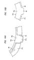
- a thrust roller bearing 71a according to the second conventional example includes a cage 72a, a plurality of rollers 73, 73 and a pair of races 74a, 74b.
- prevention of separation between one race 74a (the one on the right in Fig. 16 ) and the cage 72a is attained by a locking portion 78 which is formed in the distal edge of a cylindrical portion 77a formed in the outer circumferential edge of the outer race 74a.
- fastening protrusions 80a respectively.
- a shaft member 83 serving as a mating member on which the thrust roller bearing 71a is to be mounted specifically, in such portion of the shaft member 83 outer circumferential surface as exists near to a step surface 84, there is formed a catching groove 82a such that it extends over the whole periphery of such portion.
- the cylindrical portion 77b may be fitted with the outer surface of the shaft member 83 and also the respective fastening protrusions 80a may be engaged with the catching groove 82a.
- the thrust roller bearing 71a is mounted on the shaft member 83 such that the former is prevented from being separated from the latter unexpectedly. This can facilitate the mounting operation of a rotation-type mechanical apparatus such a transmission.
- a thrust roller bearing used to support a thrust load which is generated by hydraulic liquid flowing between the impeller and turbine.
- the stator which serves as the support surface of the thrust race of the thrust roller bearing, is generally made of aluminum in view of reducing weight and improving fuel efficiency of a vehicle. Therefore, under the actual vehicle use environment, there is the following possibility. That is, due to the relative rotation between the stator and thrust race, the support surface of the stator can be worn; and, when such wear progresses, the proper dimensional relationship between the stator and thrust race can be lost, resulting in the trouble of the vehicle.
- a thrust roller bearing 100 which is shown in Fig. 17 and is applied to a torque converter, there are provided a plurality of rotation preventing protrusions 102 on the outer periphery of its thrust race 101, and the rotation preventing protrusions 102 are respectively fitted into their associated hydraulic fluid grooves 104 formed in a stator 103, thereby preventing relative rotation between the stator 103 and thrust race 101 (see, for example, the Patent Document 3).
- a cylindrical portion 105 in the inner circumferential edge of the thrust race 101, there is formed a cylindrical portion 105 and, on the edge portion of the distal end of the cylindrical portion 105, a plurality of retaining projections 107 are formed by radially outward upsetting to prevent a cage 106 from falling out.
- the thrust race 101 is increased in size, which increases the material cost thereof.
- the present invention aims at solving the problems found in the above-mentioned conventional thrust roller bearings.
- a thrust roller bearing which can realize both the maintenance of the durability of such portion of the thrust roller bearing as backs up its race in a state where such portion is low in rigidity and the reduction of the manufacturing cost of the thrust roller bearing.
- Another object of the invention is to provide a thrust roller bearing and a method for manufacturing a thrust race thereof, according to which, in the thrust race thereof, there can be provided a protrusion securable to a mating member on which the thrust race is to be mounted, with the rigidity of the protrusion enhanced, without increasing the number of manufacturing operations.
- the plurality of race-retaining locking portions for preventing the thrust race and the mating member from separating are provided as the protrusions obtained by causing, not the axially intermediate portions of the cylindrical portion, but the portions closer to the race portion from the bottom edges of the respective cutout portions, to protrude in the radial direction. Therefore, even when the thickness dimension of a metal plate for forming the race is large to a certain degree, the race-retaining locking portions can be formed without so much cost. This makes it possible to realize a thrust roller bearing which can ensure its durability even when the rigidity of a portion backing up the thrust race is low, and also can reduce manufacturing cost.
- the thickness of a hard metal plate for forming the race can be ensured while suppressing manufacturing cost. Further, when portions of the cylindrical portion are used to form the respective race-retaining locking portions, axially recessed cutout portions are provided. Therefore, a sufficient amount of lubricating oil can be supplied through these cutout portions to an internal space where the rollers are arranged.
- the cylindrical portion of the thrust race is formed with protrusions which protrude in the radial direction away from the race portion and each having a certain width in the circumferential direction. Therefore, the protrusions having improved rigidity can be formed without increasing the number of manufacturing operations, and the thrust race is configured in a compact manner.
- the thrust roller bearing thrust race manufacturing method of the invention by bending an annular metal plate by press forming, the cylindrical portion is formed in the circumferential edge of the race portion, and simultaneously, protrusions are formed on the cylindrical portion to protrude in the radial direction away from the race portion and with a certain width in the circumferential direction. Therefore, the protrusions having improved rigidity can be formed without increasing manufacturing cost, and the thrust race is configured in a compact manner.
- Fig. 1 shows a thrust roller bearing according to a first embodiment of the invention.
- a thrust roller bearing 1 includes radially arranged rollers 2, a cage 3 which is formed to have an annular shape as a whole and also is used to rollably hold the plurality of rollers 2, and first and second thrust races 4 and 5 respectively for holding the plurality of rollers 2 from both sides in the axial direction of the rollers 2.
- the cage 3 includes two metal plates, each of which is formed to have an annular shape as a whole and also have a U-shaped section, and the two metal plates are combined together such that their respective outside and inside ring-shaped portions are superimposed on top of each other.
- the cage 3 includes the same number of pockets 3a as the rollers 2 which are formed at the plurality of locations along the circumferential direction on the cage 3. Each pocket 3a faces in the radial direction of the cage 3, while the pockets 3a are respectively arranged in the radial direction of the thrust roller bearing 1.
- the plurality of rollers 2 are to be rollably held within their associated pockets 3 a.
- the first thrust race 4 includes an annular race portion 6 with which the rolling surfaces of the plurality of rollers 2 can be rollingly contacted, and an inside cylindrical portion 7 which is formed in the inner circumferential edge of the race portion 6 in the axial direction thereof to extend over the whole periphery thereof and also which exists on the side where the respective rollers 2 are disposed.
- the second thrust race 5 includes an annular race portion 8 with which the rolling surfaces of the plurality of rollers 2 can be rollingly contacted, and an outside cylindrical portion 9 which is formed in the outer circumferential edge of the race portion 8 in the axial direction thereof to extend over the whole periphery thereof and also which exists on the side where the respective rollers 2 are disposed.
- the first and second thrust races 4 and 5 are respectively supported on first and second members 20 and 21 which are respectively used as their mating members.
- first thrust race 4 the back surface of the race portion 6 is contacted with the opposing surface 20a of the first member 20 and the inside cylindrical portion 7 is fitted with the annular shaft portion 20b of the first member 20.
- second thrust race 5 the back surface of the race portion 8 is contacted with the opposing surface 21a of the second member 21.
- a plurality of (in the present embodiment, four) protrusions 10 which respectively project in the opposite direction to the race portion 6 in the radial direction of the inside cylindrical portion 7, that is, inwardly in the radial direction thereof, and also each of which has a given width in the circumferential direction of the inside cylindrical portion 7.
- the protrusions 10 can be respectively fitted into their associated groove portions 20c respectively formed in the annular shaft portion 20b of the first member 20, whereby they can be respectively line contacted with the groove portions 20c in the circumferential direction thereof to prevent the first thrust race 4 from rotating with respect to the first member 20.
- the distal ends of the protrusions 10 are so formed as to exit closer to the race portion 6 in the axial direction of the thrust roller bearing than the distal edge 7a of the inside cylindrical portion 7. That is, at the plurality of locations in the circumferential direction on the inside cylindrical portion 7, other than the base end portions of the inside cylindrical portion 7 existing near to the race portion 6, there are formed cutout portions 7b which are respectively recessed, in the axial direction of the cylindrical portion 7, closer to the race portion 6 than the distal edges 7a of the inside cylindrical portion 7.
- the respective protrusions 10 are respectively formed using the uncut base end portions of the inside cylindrical portion 7 which exist at the same positions as the cutout portions 7b in the circumferential direction of the inside cylindrical portion 7.
- the distal edge portion 7a of the inside cylindrical portion 7 of the first thrust race 4 specifically, at positions different from the protrusions 10 in the circumferential direction of the inside cylindrical portion 7, there are formed a plurality of (in the present embodiment, four) locking projections 11 which are respectively projected by calking outwardly in the radial direction of the inside cylindrical portion 7.
- the locking projections 11 abut the inside diameter side lateral surface of the cage 3 to confine the cage 3.
- annular flat metal plate W which is a thrust race blank as shown in Fig. 4
- the annular metal plate W before press formed, includes a cutout Wa which is exists in the portion for forming the protrusion 10 and is formed by cutting it out outwardly in the radial direction of the metal plate W from the circumferential surface of the metal plate W.
- the working machine includes an annular movable support member 51 for supporting the metal plate W, a cylindrical fixed punch 52 to be inscribed in the movable support member 51 and a movable die 53 to be disposed upwardly of the movable support member 51 and fixed punch 52.
- the metal plate W is put on the movable support member 51.
- the movable support member 51 is also pressed downwardly with respect to the fixed punch 52, whereby, between the outer circumferential surface of the fixed punch 52 and the inner circumferential surface of the movable die 53, the inside cylindrical portion 7 is bent worked substantially at right angles with respect to the race portion 6.
- each escape portion 52a can be set according to the given circumferential direction width of each protrusion 10.
- the protrusions are provided 10 by forming the cutouts Wa in this manner, the bending amounts of such portions of the metal plate W as are stored between the escape portions 52a of the fixed punch 52 and the inner circumferential surface of the movable die 53 when they are pulled and bent by the inside cylindrical portion 7 bent substantially at right angles are small; and, the projecting amounts of the protrusions 10 when they are projected inwardly from the inside cylindrical portion 7 are large.
- the protrusions 10 are provided without forming the cutout portions, such portions of the metal plate W as are stored between the escape portions 52a of the fixed punch 52 and the inner circumferential surface of the movable die 53 are pulled and bent greatly by the inside cylindrical portion 7, whereas the projecting amounts of the protrusions 10 when they are projected inwardly from the inside cylindrical portion 7 are small. Therefore, the projecting amounts of the protrusions 10 can be adjusted by adjusting the size of the cutouts Wa.
- the method for manufacturing the thrust race 4 of the thrust roller bearing 1 by bending the annular metal plate W by press forming, simultaneously when the inside cylindrical portion 7 is formed in the inner circumferential edge of the race portion 6, in the inside cylindrical portion 7, there can be provided the protrusions 10 which are respectively projected inwardly in the radial direction of the inside cylindrical portion 7 and also respectively have a given width in the circumferential direction. That is, without increasing the number of manufacturing operations, there can be formed the protrusions 10 which are enhanced in rigidity, and there can be produced the thrust race 4 that has a compact structure.
- the protrusions 10 which are respectively projected inwardly in the radial direction of the inside cylindrical portion and also respectively have a given width in the circumferential direction.
- the protrusions 10 can be line contacted with the first member 20 supporting the thrust race 4 in the circumferential direction thereof, thereby being able to prevent the thrust race 4 from rotating with respect to the first member 20. Accordingly, there can be formed the protrusions 10 which are enhanced in rigidity and can cooperate together to provide a rotation preventive function, and there can be produced the thrust race 4 that has a compact structure.
- Fig. 5 shows a thrust roller bearing according to a second embodiment of the invention.
- the same or equivalent parts of the present embodiment to the first embodiment are given the same designations and thus the description thereof is saved or simplified.
- a first thrust race 4 is configured such that the back surface of its race portion 6 contacts the opposing surface 20a of a first member 20, and the second thrust race 5 is configured such that the back surface of its race portion 8 contacts the opposing surface 21a of a second member 21 and such that its outside cylindrical portion 9 is fitted in the annular recessed portion 21b of the second member 21.
- a plurality of (in the present embodiment, four) protrusions 10a each having a given width in the circumferential direction of the outside cylindrical portion 9 such that, in the radial direction of the outside cylindrical portion 9, they respectively project in the opposite direction to the race portion 6, that is, outwardly in the radial direction of the outside cylindrical portion 9.
- the protrusions 10a are respectively fitted into groove portions 21c respectively formed in the annular recessed portions 21b of the second member 21 in a line contact manner in the circumferential direction of the outside cylindrical portion 9, thereby being able to prevent the second thrust race 5 from rotating with respect to the second member 21.
- each protrusion 10a is formed to exist in the axial direction of the outside cylindrical portion 9 closer to the race portion than the distal edge 9a of the outside cylindrical portion 9. That is, at the plurality of locations along circumferential direction on the outside cylindrical portion 9 in the other portions of the outside cylindrical portion 9 than the base end portion thereof that is situated near to the race portion 6, with respect to the axial direction of the outside cylindrical portion 9, there formed cutout portions 9b which are respectively recessed further toward the race portion 6 than the distal edges 9a of the outside cylindrical portion 9.
- the protrusions 10a are respectively formed using the uncut base end portion of the outside cylindrical portion 9 that exists at the same position as the cutout portions 9b in the circumferential direction of the outside cylindrical portion and remains uncut.
- an annular metal plate W' is press formed using a working machine as shown in Fig. 7 including a movable support member 61, a fixed die 62 and a movable punch 63, there can be formed the outside cylindrical portion 9 that is bent worked substantially at right angles in the outer circumferential edge of the race portion 8.
- the fixed die 62 as shown in Fig. 7B , there is formed an escape portion 62a locally in the circumferential surface thereof.
- the portion of the metal plate W' which is stored between the escape portion 62a of the fixed die 62 and the outer circumferential surface of the movable punch 63, is not bent at right angles but is projected outwardly in the radial direction, thereby forming the protrusion 10a.
- the projecting amount of each protrusion 10a can be adjusted by adjusting the size of a cutout portion Wa' obtained by cutting out the outer circumferential surface of the metal plate W' inwardly in the radial direction.
- the thrust race 5 of the thrust roller bearing 1a by bending the annular metal plate W' by press forming, simultaneously when the outside cylindrical portion 9 is formed in the outer circumferential edge of the race 8, in the outside cylindrical portion 9, there can be formed the protrusions 10a which respectively project outwardly in the radial direction of the outside cylindrical portion 9 and respectively have a given width in the circumferential direction. Therefore, without increasing the number of manufacturing operations, there can be formed the protrusions 10a the rigidity of which is enhanced, and the structure of the thrust race 5 can be made compact.
- the protrusions 10a respectively projecting outwardly in the radial direction and having a given width in the circumferential direction.
- the protrusions 10a can be line contacted in the circumferential direction of the thrust race 5 with the second member 21 which is supporting the thrust race 5, thereby providing a rotation preventive function to prevent the thrust race 5 from rotating with respect to the second member 21. Therefore, there can be formed such protrusions 10a as are enhanced in rigidity and have the rotation preventive function, and the structure of the thrust race 5 can be made compact.
- Figs. 8 and 9 respectively show a thrust roller bearing 71b according to a third embodiment of the invention.
- the invention is applied to a structure, in which the thrust roller bearing 71b is mounted into a retaining recess 86 formed in its mating member, that is, a housing 85 and the thrust roller bearing 71b is prevented from moving out from the retaining recess 86 unexpectedly.
- the thrust roller bearing 71b includes a cage 72b, a plurality of rollers 73 and a race 74c.
- the cage 72b is ring-shaped and includes a plurality of pockets 75a which are formed at a plurality of locations along the circumferential direction so as to be oriented in the radial direction.
- a pair of cage elements 87a, 87b which have been respectively produced by bent working their associated metal plates to thereby have a U-shaped section, may be combined together in such a manner their respective outside and inside ring-shaped portions are superimposed on top of each, thereby forming a hollow ring-shaped product.
- the respective pockets 75a are structured by combining together rectangular-shaped through holes 88 and 88 which have been respectively formed in the mutually corresponding portions of the two cage elements 87a, 87b.
- each through hole 88 is set slightly smaller than the outside diameter of each roller 73.
- the two cage elements 87a, 87b are connected to each other such that the respective rollers 73 are interposed between the through holes 88, 88 to thereby prevent the two cage elements 87a, 87b against separation from each other, thereby completing the cage 72b.
- the respective rollers 73 are held such that they are free to roll within their associated pockets 75a and also they are prevented from moving out from the respective pockets 75a.
- the race 74c can be obtained by bending a metal plate made of hard metal such as carbon steel or hardened steel, while it includes a race portion 76a and a cylindrical portion 77c.
- the race portion 76a of the race 74c is a portion with which the rolling surface of each roller 73 can be rollingly contacted, and also which has an annular shape.
- the cylindrical portion 77c is formed in the outer circumferential edge of the race portion 76a by bending a metal plate such that, with respect to the axial direction of the race 74c, the metal plate is directed on the side where the respective rollers 73 are displaced and is bent in the upward direction in Figs. 8 and 9 .
- the cage 72b is disposed on the inside diameter side of the cylindrical portion 77c such that the cage 72b and the race 74c can be rotated relative to each other.
- the inside diameter of the cylindrical portion 77c is set slightly larger than the outside diameter of the cage 72b.
- cage-retaining locking portions 89 which are respectively bent inwardly in the radial direction of the cylindrical portion 77c.
- the diameters of the inscribed circles of these cage-retaining locking portions 89 are set slightly smaller than the outside diameter of the cage 72b. Due to this, the cage 72b and the race 74c are combined together such that they can be rotated relative to each other and they can be prevented from separating from each other.
- the cylindrical portion 77c is discontinuous over the whole width thereof in the respective cutout portions 90.
- the diameters of such portions (the circumscribed circles) of the outer circumferential edge of the race portion 76a as correspond to the respective cutout portions 90 are set larger than the diameters of the other portions (the portions where the cylindrical portion 77c is formed), whereby such portions are projected outwardly in the radial direction of the cylindrical portion 77c further than the cylindrical portion 77c.
- the projected portions are used as race-retaining locking portions 91.
- these race-retaining locking portions 91 are respectively formed to have a projecting arc shape.
- the diameter D 91 of the circumscribed circle of each race-retaining locking portion 91 in a free state where no external force is applied to the race 74c, is set slightly larger than the outside diameter D 77c of the cylindrical portion 77c and is also set slightly larger than the inside diameter R 86 of the near-to-opening portion of the retaining recess 86 which will be discussed below (D 91 >R 86 >D 77c ).
- the thrust roller bearing 71b having above-structure In order to assemble or mount the thrust roller bearing 71b having above-structure into the housing 85, in the inner circumferential surface of the deep end portion of the retaining recess 86 formed in the housing 85, there is formed a catching groove 82b over the whole periphery thereof.
- the race-retaining locking portions 91 may be pushed into the retaining recess 86 and, at the same time, the cylindrical portion 77c may be fitted into the retaining recess 86.
- the distal end portions of the race-retaining locking portions 91 may be engaged into the catching groove 82b.
- the thrust roller bearing 71b is assembled to the housing 85 such that it is prevented against separation from the housing 85. This can facilitate the assembling operation of a rotation-type mechanical apparatus such as a transmission.
- each race-retaining locking portion 91 has a projecting are shape the width of which decreases as it approaches the distal end thereof, the respective race-retaining locking portions 91 are easy to deform elastically, whereby the engaging operation to engage them with the catching groove 82b can be carried out with a relatively light force.
- the thrust roller bearing 71b which can secure the durability thereof in a state where the back-up portion for backing up the race 74c is low in rigidity and also can reduce the manufacturing cost thereof.
- the plurality of race-retaining locking portions 91 for prevention of separation between the race 74c and housing 85 are formed not in the axial direction intermediate portion of the cylindrical portion 77c but in such portion of the outer circumferential edge of the race portion 76a as exists in the discontinuous portion of the cylindrical portion 77c such that a portion of the race portion 76a is extended outwardly in the diameter portion of the race portion 76a.
- the operation to work the race-retaining locking portions 91 can be carried out without increasing the cost thereof so much. That is, a metal plate as a blank is punched, for example by pressing, to form a flat-plate-shaped intermediate work including portions for forming the race portion 76a, race-retaining locking portions 91 and cylindrical portion 77c. Thereafter, the portion of the intermediate work for forming the cylindrical portion 77c is bent with respect to the portion of the intermediate member for forming the race portion 76a. In this case, there can be formed the race portion 76a, race-retaining locking portions 91 and cylindrical portion 77c simultaneously.
- the portions of the cylindrical portion 77c where the respective race-retaining locking portions 91 are formed at the plurality of locations along circumferential direction are respectively formed as the cutout portions 90 which are recessed in the axial direction of the cylindrical portion 77c, a sufficient amount of lubricating oil can be supplied through these cutout portions 90 to the internal space where the respective rollers 73 are provided. Therefore, even under a severe use condition, for example, even under a condition where the rotation speed is high and a thrust load to be applied is large, it is possible to prevent the rolling contact portion and sliding contact portion of the thrust roller bearing against damage such as abnormal abrasion and seizure.
- a thrust roller bearing of the invention Owing to the above effects, according to a thrust roller bearing of the invention, the durability thereof can be ensured and the manufacturing cost thereof can be reduced at the same time even when the rigidity of the portion for backing up the race 74c is low because the composing material of the housing 85 is soft or because the thickness of the housing 85 is small, or even when the back-up portion is discontinuous in part in the circumferential direction or in the radial direction (that is, the back-up surface is uneven) due to the existence of the recessed groove in the back-up portion.
- Fig. 10 shows a thrust roller bearing according to a fourth embodiment of the invention.
- each of race-retaining locking portions 91a which are respectively formed at the plurality of locations along circumferential direction on a race portion 76a of a race 74d, is formed to have a substantially trapezoid which can be obtained by rounding an angle.
- the widths of the distal edges of the respective race-retaining locking portions 91a are large, even in the case that, while the race 74d is being delivered, the distal edges of the respective race-retaining locking portions 91a happen to collide with any one of other composing members, the surface of the composing member can be made harder to be damaged.
- the structures and operations of the other remaining portions of the present embodiment are similar to those of the previously described third embodiment, and thus the duplicate illustration and description thereof are omitted here.
- Figs. 11 and 12 respectively show a thrust roller bearing according to a fifth embodiment of the invention.
- a cylindrical portion 77d which is formed in the outer circumferential edge of a race portion 76a of a race 74e, specifically, the base end portion thereof existing near the race portion 76a is formed to extend continuously over the whole periphery thereof.
- race-retaining locking portions 91b are formed in the circumferential direction intermediate portion of the uncut base end portion.
- the portion the phase with respect to the circumferential direction of which coincides with the central portions of the respective cutout portions 90a may be expanded partially cylindrically in the opposite direction to the race portion 76a with respect to the radial direction of the cylindrical portion 77d.
- the axial direction dimensions of the respective race-retaining locking portions 91b are longer than those of the previously described third and fourth embodiments.
- the width dimensions of a catching groove 82c to be formed in the inner circumferential surface deep end portion of the retaining recess 86a of a housing 85a are set wider than those of the third and fourth embodiments.
- the respective race-retaining locking portions 91b can collide with their mating members, thereby being able to prevent the race-retaining locking portions 91 from scratching or damaging their mating members.
- an unreasonable force can be made harder to be applied to the respective race-retaining locking portions 91b, thereby being able to prevent the race-retaining locking portions 91b against damage such a crack.
- the structures and operations of the other remaining portions of the present embodiment are similar to those of the previously described third and fourth embodiments, and thus the duplicate description thereof is omitted here.
- Fig. 13 shows a thrust roller bearing according to a sixth embodiment of the invention.
- the respective race-retaining locking portions 91c are formed such that they are expanded in a wedge-like manner in the opposite direction to the race portion 76a with respect to the radial direction. That is, the respective race-retaining locking portions 91c are inclined such that the projecting amounts thereof from the outer circumferential surface of the cylindrical portion 77d outwardly in the radial direction are small on the race portion 76a side and, as they become more distant from the race portion 76a, the projecting amounts increase.
- race-retaining locking portions 91c when compared with the previously described race-retaining locking portions 91b according to the fifth embodiment, an operation to engage the race-retaining locking portions 91c with the catching groove 82c (see Fig. 11 ) can be facilitated.
- the cylindrical portion 77d is formed by drawing a metal plate including portions which are respectively used to provide cutout portions and, at the same time, of the base end portion of the cylindrical portion 77d, the portion thereof the phase with respect to the circumferential direction of which coincides with the central portions of the respective cutout portions is expanded, the race-retaining locking portions 91c can be worked easily, and thus the cost of the race 74f can be reduced.
- the bulging amount of the bulged portion can be adjusted by adjusting the size (the depth) of the respective cutouts.
- Fig. 14 shows a thrust roller bearing according to a seventh embodiment of the invention.
- a thrust roller bearing 71d is to be assembled to its mating member, that is, a shaft member 83a.
- a shaft member 83a For this purpose, in this embodiment, at the plurality of locations on the inner circumferential edge of a race portion 76b of a race 74g, there are formed race-retaining locking portions 91d respectively. These race-retaining locking portions 91d are respectively engaged into a catching groove 82d formed in the outer circumferential surface of the shaft member 83a, whereby the shaft member 83a and thrust roller bearing 71d including the race 74g can be prevented from separating from each other.
- the present invention is not limited to the embodiments described above, and can be changed or modified as needed.
- the above embodiments can also be combined within the enable range.
- the protrusions to be formed simultaneously with the formation of the cylindrical portion according to the invention may also have a rotation preventive function, and they may also have a function to position the thrust race in the axial direction thereof with respect to its mating member on which the thrust race is to be mounted.
- a rotation preventive function may also have a function to position the thrust race in the axial direction thereof with respect to its mating member on which the thrust race is to be mounted.
- the shape of the cage is not limited to one employed according to the above embodiments but it may also be structured by a single piece of metal plate including a plurality of pockets punched along the circumferential direction thereof.
- a thrust roller bearing according to the invention may have at least a thrust race including protrusions. That is, the above-mentioned three to seventh embodiments respectively show a case in which the invention is applied to a structure having a race only on one side of the cage and rollers.
- Such structure can be implemented when a member to be disposed on the other side of the cage and roller is a member made of hard metal such as bearing steel and a track surface can be formed directly on the surface of this member.
- two paired members respectively existing on both sides of the cage and rollers are made of relatively soft material such as an aluminum alloy, races are disposed on both sides of the cage and rollers.
- it can also be implemented even when the radial direction thereof is reversed.
Landscapes
- Engineering & Computer Science (AREA)
- General Engineering & Computer Science (AREA)
- Mechanical Engineering (AREA)
- Manufacturing & Machinery (AREA)
- Rolling Contact Bearings (AREA)
Applications Claiming Priority (3)
| Application Number | Priority Date | Filing Date | Title |
|---|---|---|---|
| JP2009102011A JP5347679B2 (ja) | 2009-04-20 | 2009-04-20 | スラストころ軸受及びそのスラストレースの製造方法 |
| JP2009175081A JP5347804B2 (ja) | 2009-07-28 | 2009-07-28 | レース付スラストころ軸受 |
| PCT/JP2010/052901 WO2010122838A1 (fr) | 2009-04-20 | 2010-02-24 | Palier de butée à rouleaux et procédé de fabrication de bague de roulement de butée |
Publications (3)
| Publication Number | Publication Date |
|---|---|
| EP2423524A1 true EP2423524A1 (fr) | 2012-02-29 |
| EP2423524A4 EP2423524A4 (fr) | 2016-09-21 |
| EP2423524B1 EP2423524B1 (fr) | 2018-04-18 |
Family
ID=43010962
Family Applications (1)
| Application Number | Title | Priority Date | Filing Date |
|---|---|---|---|
| EP10766898.0A Active EP2423524B1 (fr) | 2009-04-20 | 2010-02-24 | Palier de butée à rouleaux et procédé de fabrication de bague de roulement de butée |
Country Status (4)
| Country | Link |
|---|---|
| US (2) | US8876400B2 (fr) |
| EP (1) | EP2423524B1 (fr) |
| CN (1) | CN102138017B (fr) |
| WO (1) | WO2010122838A1 (fr) |
Families Citing this family (12)
| Publication number | Priority date | Publication date | Assignee | Title |
|---|---|---|---|---|
| JP2013079718A (ja) * | 2011-09-20 | 2013-05-02 | Nsk Ltd | レース付スラストころ軸受 |
| USD772964S1 (en) | 2014-01-17 | 2016-11-29 | Thk Co., Ltd. | Roller bearing |
| USD771166S1 (en) * | 2014-06-19 | 2016-11-08 | Nsk Ltd. | Tapered roller bearing cage |
| JP1523819S (fr) * | 2014-09-16 | 2015-05-18 | ||
| JP1523820S (fr) * | 2014-09-16 | 2015-05-18 | ||
| JP1523821S (fr) * | 2014-09-16 | 2015-05-18 | ||
| JP1550608S (fr) * | 2015-07-10 | 2016-05-30 | ||
| JP7416683B2 (ja) * | 2017-07-21 | 2024-01-17 | コーヨー ベアリングス ノース アメリカ エルエルシー | 短縮されたフランジを有するスラスト・ベアリング・ケージ |
| JP1645893S (fr) * | 2019-01-10 | 2019-11-18 | ||
| CN111546004A (zh) * | 2020-05-11 | 2020-08-18 | 漳州润时达轴承制造有限公司 | 一种平面止推轴承制备方法 |
| CN112658099B (zh) * | 2020-12-16 | 2022-08-05 | 宁波人和机械轴承有限公司 | 一种轴承防尘盖冲压用柔性保护平台 |
| CN113653731B (zh) * | 2021-07-01 | 2022-11-29 | 聊城鲁寰轴承有限公司 | 一种适用于重载低速工况下的推力球轴承 |
Family Cites Families (24)
| Publication number | Priority date | Publication date | Assignee | Title |
|---|---|---|---|---|
| US3900235A (en) * | 1971-12-30 | 1975-08-19 | Torrington Co | Tab race |
| JPS5924530U (ja) * | 1982-08-09 | 1984-02-15 | 日本精工株式会社 | 非分離型複合軸受 |
| JPH0716101Y2 (ja) * | 1987-07-17 | 1995-04-12 | 光洋精工株式会社 | スラストころ軸受の固定構造 |
| US4783183A (en) * | 1987-12-28 | 1988-11-08 | The Torrington Company | Thrust bearing assembly |
| JP2511521Y2 (ja) * | 1990-08-28 | 1996-09-25 | 光洋精工株式会社 | ラジアル・スラスト組み合わせ軸受 |
| US5647675A (en) | 1993-07-17 | 1997-07-15 | Ina Walzlager Schaeffler Kg | Angular thrust disc |
| JP3316307B2 (ja) * | 1994-06-07 | 2002-08-19 | 日本トムソン株式会社 | スラスト軸受 |
| US5647875A (en) * | 1994-12-02 | 1997-07-15 | Clariant Finance (Bvi) Limited | Method for producing a color effect on textile material |
| NL1003233C2 (nl) * | 1996-05-30 | 1997-12-03 | Skf Ind Trading & Dev | Werkwijze voor het vervaardigen van een lagerring en een lager dat een dergelijke lagerring omvat. |
| US5967673A (en) * | 1997-03-17 | 1999-10-19 | The Torrington Company | Axially oriented anti-rotation feature for lipped thrust races |
| US5967674A (en) * | 1998-07-15 | 1999-10-19 | Torrington Co | Selective washer and thrust bearing assembly |
| JP2002098156A (ja) * | 2000-09-26 | 2002-04-05 | Ntn Corp | スラスト針状ころ軸受 |
| JP3971626B2 (ja) * | 2002-02-25 | 2007-09-05 | 株式会社ユタカ技研 | トルクコンバータ |
| US6830381B2 (en) * | 2002-04-03 | 2004-12-14 | Ina-Schaeffler Kg | Axial roller bearing |
| DE10227377B4 (de) | 2002-06-20 | 2004-11-11 | Ina-Schaeffler Kg | Axialwinkelscheibe |
| DE10306926B4 (de) * | 2003-02-19 | 2012-02-09 | Schaeffler Technologies Gmbh & Co. Kg | Axiallager |
| JP2007040498A (ja) * | 2005-08-05 | 2007-02-15 | Jtekt Corp | スラストころ軸受 |
| WO2008090703A1 (fr) * | 2007-01-24 | 2008-07-31 | Ntn Corporation | Butée à rouleau et convertisseur de couple |
| JP5081002B2 (ja) | 2008-01-28 | 2012-11-21 | 株式会社日立製作所 | Nmr用アンテナコイル、それに使用する低磁性超電導線材とその製造方法並びに磁化率調整方法、及びnmrシステム |
| DE102008016880B4 (de) * | 2008-04-02 | 2017-05-04 | Schaeffler Technologies AG & Co. KG | Axiallager mit einer Axialwinkelscheibe mit einer eine Montagesicherung darstellenden Haltezunge und Träger mit einem solchen Axiallager |
| JP4729628B2 (ja) | 2009-02-06 | 2011-07-20 | 北海道旅客鉄道株式会社 | 列車及び鉄道列車搬入搬出方法 |
| JP5712641B2 (ja) * | 2011-01-28 | 2015-05-07 | 日本精工株式会社 | 脱落防止用突起付きスラスト軸受 |
| EP2672131B1 (fr) * | 2011-02-02 | 2017-05-17 | NSK Ltd. | Butée à rouleaux |
| JP2013079718A (ja) * | 2011-09-20 | 2013-05-02 | Nsk Ltd | レース付スラストころ軸受 |
-
2010
- 2010-02-24 US US13/060,709 patent/US8876400B2/en active Active
- 2010-02-24 CN CN201080002463.1A patent/CN102138017B/zh active Active
- 2010-02-24 WO PCT/JP2010/052901 patent/WO2010122838A1/fr active Application Filing
- 2010-02-24 EP EP10766898.0A patent/EP2423524B1/fr active Active
-
2014
- 2014-02-20 US US14/184,871 patent/US9261135B2/en active Active
Non-Patent Citations (1)
| Title |
|---|
| See references of WO2010122838A1 * |
Also Published As
| Publication number | Publication date |
|---|---|
| US20110158573A1 (en) | 2011-06-30 |
| US9261135B2 (en) | 2016-02-16 |
| US8876400B2 (en) | 2014-11-04 |
| EP2423524B1 (fr) | 2018-04-18 |
| WO2010122838A1 (fr) | 2010-10-28 |
| CN102138017B (zh) | 2014-02-26 |
| EP2423524A4 (fr) | 2016-09-21 |
| CN102138017A (zh) | 2011-07-27 |
| US20140169721A1 (en) | 2014-06-19 |
Similar Documents
| Publication | Publication Date | Title |
|---|---|---|
| EP2423524B1 (fr) | Palier de butée à rouleaux et procédé de fabrication de bague de roulement de butée | |
| JP4790341B2 (ja) | 針状ころ軸受および軸受構造 | |
| EP1653095A2 (fr) | Butée à deux rangées de rouleaux avec une cage possédant des nez de retention formés par déformation plastique | |
| EP1881213B1 (fr) | Butée à rouleaux | |
| JP6497833B2 (ja) | 保持器付き針状ころ | |
| US8944696B2 (en) | Cage for radial roller bearing | |
| EP2103825A1 (fr) | Dispositif de retenue pour butée à rouleaux et butée à rouleaux | |
| JP4661424B2 (ja) | 回転支持部 | |
| JP5458795B2 (ja) | 歯車機構の軸受装置 | |
| US7736066B2 (en) | Thrust cylindrical roller bearing | |
| JP2018105500A (ja) | スラストころ軸受及びスラストころ軸受用軌道輪 | |
| EP1418351B1 (fr) | Disposition de palier supportant la poussée axiale d'un compresseur avec une butée à deux rangées de rouleaux | |
| JP2008002503A (ja) | スラストころ軸受 | |
| JP4480636B2 (ja) | 針状ころ軸受 | |
| JP2010014222A (ja) | ローラ型ワンウェイクラッチの外輪の加工方法 | |
| EP2628968A1 (fr) | Organe d'espacement libre formant un alvèole ouvert destiné à recevoir un rouleau, notamment pour une butée à rouleaux d'une machine de percement des tunnels | |
| CN101368598A (zh) | 轴承保持方法和装置 | |
| JP4480639B2 (ja) | 針状ころ軸受および外輪の製造方法 | |
| JP5029430B2 (ja) | スラストころ軸受装置 | |
| JP2015031390A (ja) | スラストころ軸受 | |
| JP2008014414A (ja) | スラストころ軸受 | |
| EP3085977A1 (fr) | Cage pour roulement à billes radial | |
| JP2008025591A (ja) | スラストころ軸受用保持器の製造方法 | |
| JP4563885B2 (ja) | 針状ころ軸受 | |
| EP2628967A1 (fr) | Organe d'espacement libre en forme de C avec alvèole destiné à recevoir un rouleau, notamment pour une butée à rouleaux d'une machine de percement des tunnels |
Legal Events
| Date | Code | Title | Description |
|---|---|---|---|
| PUAI | Public reference made under article 153(3) epc to a published international application that has entered the european phase |
Free format text: ORIGINAL CODE: 0009012 |
|
| 17P | Request for examination filed |
Effective date: 20110225 |
|
| AK | Designated contracting states |
Kind code of ref document: A1 Designated state(s): AT BE BG CH CY CZ DE DK EE ES FI FR GB GR HR HU IE IS IT LI LT LU LV MC MK MT NL NO PL PT RO SE SI SK SM TR |
|
| DAX | Request for extension of the european patent (deleted) | ||
| REG | Reference to a national code |
Ref country code: DE Ref legal event code: R079 Ref document number: 602010050029 Country of ref document: DE Free format text: PREVIOUS MAIN CLASS: F16C0033640000 Ipc: F16C0019300000 |
|
| RA4 | Supplementary search report drawn up and despatched (corrected) |
Effective date: 20160824 |
|
| RIC1 | Information provided on ipc code assigned before grant |
Ipc: F16C 33/58 20060101ALI20160818BHEP Ipc: F16C 35/06 20060101ALI20160818BHEP Ipc: F16C 33/64 20060101ALI20160818BHEP Ipc: F16C 19/30 20060101AFI20160818BHEP |
|
| STAA | Information on the status of an ep patent application or granted ep patent |
Free format text: STATUS: EXAMINATION IS IN PROGRESS |
|
| 17Q | First examination report despatched |
Effective date: 20170412 |
|
| GRAP | Despatch of communication of intention to grant a patent |
Free format text: ORIGINAL CODE: EPIDOSNIGR1 |
|
| STAA | Information on the status of an ep patent application or granted ep patent |
Free format text: STATUS: GRANT OF PATENT IS INTENDED |
|
| INTG | Intention to grant announced |
Effective date: 20171106 |
|
| GRAS | Grant fee paid |
Free format text: ORIGINAL CODE: EPIDOSNIGR3 |
|
| GRAA | (expected) grant |
Free format text: ORIGINAL CODE: 0009210 |
|
| STAA | Information on the status of an ep patent application or granted ep patent |
Free format text: STATUS: THE PATENT HAS BEEN GRANTED |
|
| AK | Designated contracting states |
Kind code of ref document: B1 Designated state(s): AT BE BG CH CY CZ DE DK EE ES FI FR GB GR HR HU IE IS IT LI LT LU LV MC MK MT NL NO PL PT RO SE SI SK SM TR |
|
| REG | Reference to a national code |
Ref country code: GB Ref legal event code: FG4D |
|
| REG | Reference to a national code |
Ref country code: CH Ref legal event code: EP |
|
| REG | Reference to a national code |
Ref country code: AT Ref legal event code: REF Ref document number: 990818 Country of ref document: AT Kind code of ref document: T Effective date: 20180515 |
|
| REG | Reference to a national code |
Ref country code: IE Ref legal event code: FG4D |
|
| REG | Reference to a national code |
Ref country code: DE Ref legal event code: R096 Ref document number: 602010050029 Country of ref document: DE |
|
| REG | Reference to a national code |
Ref country code: NL Ref legal event code: MP Effective date: 20180418 |
|
| REG | Reference to a national code |
Ref country code: LT Ref legal event code: MG4D |
|
| PG25 | Lapsed in a contracting state [announced via postgrant information from national office to epo] |
Ref country code: NL Free format text: LAPSE BECAUSE OF FAILURE TO SUBMIT A TRANSLATION OF THE DESCRIPTION OR TO PAY THE FEE WITHIN THE PRESCRIBED TIME-LIMIT Effective date: 20180418 |
|
| PG25 | Lapsed in a contracting state [announced via postgrant information from national office to epo] |
Ref country code: ES Free format text: LAPSE BECAUSE OF FAILURE TO SUBMIT A TRANSLATION OF THE DESCRIPTION OR TO PAY THE FEE WITHIN THE PRESCRIBED TIME-LIMIT Effective date: 20180418 Ref country code: PL Free format text: LAPSE BECAUSE OF FAILURE TO SUBMIT A TRANSLATION OF THE DESCRIPTION OR TO PAY THE FEE WITHIN THE PRESCRIBED TIME-LIMIT Effective date: 20180418 Ref country code: FI Free format text: LAPSE BECAUSE OF FAILURE TO SUBMIT A TRANSLATION OF THE DESCRIPTION OR TO PAY THE FEE WITHIN THE PRESCRIBED TIME-LIMIT Effective date: 20180418 Ref country code: BG Free format text: LAPSE BECAUSE OF FAILURE TO SUBMIT A TRANSLATION OF THE DESCRIPTION OR TO PAY THE FEE WITHIN THE PRESCRIBED TIME-LIMIT Effective date: 20180718 Ref country code: LT Free format text: LAPSE BECAUSE OF FAILURE TO SUBMIT A TRANSLATION OF THE DESCRIPTION OR TO PAY THE FEE WITHIN THE PRESCRIBED TIME-LIMIT Effective date: 20180418 Ref country code: SE Free format text: LAPSE BECAUSE OF FAILURE TO SUBMIT A TRANSLATION OF THE DESCRIPTION OR TO PAY THE FEE WITHIN THE PRESCRIBED TIME-LIMIT Effective date: 20180418 Ref country code: NO Free format text: LAPSE BECAUSE OF FAILURE TO SUBMIT A TRANSLATION OF THE DESCRIPTION OR TO PAY THE FEE WITHIN THE PRESCRIBED TIME-LIMIT Effective date: 20180718 |
|
| PG25 | Lapsed in a contracting state [announced via postgrant information from national office to epo] |
Ref country code: GR Free format text: LAPSE BECAUSE OF FAILURE TO SUBMIT A TRANSLATION OF THE DESCRIPTION OR TO PAY THE FEE WITHIN THE PRESCRIBED TIME-LIMIT Effective date: 20180719 Ref country code: HR Free format text: LAPSE BECAUSE OF FAILURE TO SUBMIT A TRANSLATION OF THE DESCRIPTION OR TO PAY THE FEE WITHIN THE PRESCRIBED TIME-LIMIT Effective date: 20180418 Ref country code: LV Free format text: LAPSE BECAUSE OF FAILURE TO SUBMIT A TRANSLATION OF THE DESCRIPTION OR TO PAY THE FEE WITHIN THE PRESCRIBED TIME-LIMIT Effective date: 20180418 |
|
| REG | Reference to a national code |
Ref country code: AT Ref legal event code: MK05 Ref document number: 990818 Country of ref document: AT Kind code of ref document: T Effective date: 20180418 |
|
| PG25 | Lapsed in a contracting state [announced via postgrant information from national office to epo] |
Ref country code: PT Free format text: LAPSE BECAUSE OF FAILURE TO SUBMIT A TRANSLATION OF THE DESCRIPTION OR TO PAY THE FEE WITHIN THE PRESCRIBED TIME-LIMIT Effective date: 20180820 |
|
| REG | Reference to a national code |
Ref country code: DE Ref legal event code: R097 Ref document number: 602010050029 Country of ref document: DE |
|
| PG25 | Lapsed in a contracting state [announced via postgrant information from national office to epo] |
Ref country code: CZ Free format text: LAPSE BECAUSE OF FAILURE TO SUBMIT A TRANSLATION OF THE DESCRIPTION OR TO PAY THE FEE WITHIN THE PRESCRIBED TIME-LIMIT Effective date: 20180418 Ref country code: SK Free format text: LAPSE BECAUSE OF FAILURE TO SUBMIT A TRANSLATION OF THE DESCRIPTION OR TO PAY THE FEE WITHIN THE PRESCRIBED TIME-LIMIT Effective date: 20180418 Ref country code: RO Free format text: LAPSE BECAUSE OF FAILURE TO SUBMIT A TRANSLATION OF THE DESCRIPTION OR TO PAY THE FEE WITHIN THE PRESCRIBED TIME-LIMIT Effective date: 20180418 Ref country code: AT Free format text: LAPSE BECAUSE OF FAILURE TO SUBMIT A TRANSLATION OF THE DESCRIPTION OR TO PAY THE FEE WITHIN THE PRESCRIBED TIME-LIMIT Effective date: 20180418 Ref country code: DK Free format text: LAPSE BECAUSE OF FAILURE TO SUBMIT A TRANSLATION OF THE DESCRIPTION OR TO PAY THE FEE WITHIN THE PRESCRIBED TIME-LIMIT Effective date: 20180418 Ref country code: EE Free format text: LAPSE BECAUSE OF FAILURE TO SUBMIT A TRANSLATION OF THE DESCRIPTION OR TO PAY THE FEE WITHIN THE PRESCRIBED TIME-LIMIT Effective date: 20180418 |
|
| PLBE | No opposition filed within time limit |
Free format text: ORIGINAL CODE: 0009261 |
|
| STAA | Information on the status of an ep patent application or granted ep patent |
Free format text: STATUS: NO OPPOSITION FILED WITHIN TIME LIMIT |
|
| PG25 | Lapsed in a contracting state [announced via postgrant information from national office to epo] |
Ref country code: IT Free format text: LAPSE BECAUSE OF FAILURE TO SUBMIT A TRANSLATION OF THE DESCRIPTION OR TO PAY THE FEE WITHIN THE PRESCRIBED TIME-LIMIT Effective date: 20180418 Ref country code: SM Free format text: LAPSE BECAUSE OF FAILURE TO SUBMIT A TRANSLATION OF THE DESCRIPTION OR TO PAY THE FEE WITHIN THE PRESCRIBED TIME-LIMIT Effective date: 20180418 |
|
| 26N | No opposition filed |
Effective date: 20190121 |
|
| PG25 | Lapsed in a contracting state [announced via postgrant information from national office to epo] |
Ref country code: SI Free format text: LAPSE BECAUSE OF FAILURE TO SUBMIT A TRANSLATION OF THE DESCRIPTION OR TO PAY THE FEE WITHIN THE PRESCRIBED TIME-LIMIT Effective date: 20180418 |
|
| REG | Reference to a national code |
Ref country code: CH Ref legal event code: PL |
|
| GBPC | Gb: european patent ceased through non-payment of renewal fee |
Effective date: 20190224 |
|
| PG25 | Lapsed in a contracting state [announced via postgrant information from national office to epo] |
Ref country code: MC Free format text: LAPSE BECAUSE OF FAILURE TO SUBMIT A TRANSLATION OF THE DESCRIPTION OR TO PAY THE FEE WITHIN THE PRESCRIBED TIME-LIMIT Effective date: 20180418 Ref country code: LU Free format text: LAPSE BECAUSE OF NON-PAYMENT OF DUE FEES Effective date: 20190224 |
|
| REG | Reference to a national code |
Ref country code: BE Ref legal event code: MM Effective date: 20190228 |
|
| REG | Reference to a national code |
Ref country code: IE Ref legal event code: MM4A |
|
| PG25 | Lapsed in a contracting state [announced via postgrant information from national office to epo] |
Ref country code: CH Free format text: LAPSE BECAUSE OF NON-PAYMENT OF DUE FEES Effective date: 20190228 Ref country code: LI Free format text: LAPSE BECAUSE OF NON-PAYMENT OF DUE FEES Effective date: 20190228 |
|
| PG25 | Lapsed in a contracting state [announced via postgrant information from national office to epo] |
Ref country code: IE Free format text: LAPSE BECAUSE OF NON-PAYMENT OF DUE FEES Effective date: 20190224 Ref country code: GB Free format text: LAPSE BECAUSE OF NON-PAYMENT OF DUE FEES Effective date: 20190224 |
|
| PG25 | Lapsed in a contracting state [announced via postgrant information from national office to epo] |
Ref country code: BE Free format text: LAPSE BECAUSE OF NON-PAYMENT OF DUE FEES Effective date: 20190228 Ref country code: FR Free format text: LAPSE BECAUSE OF NON-PAYMENT OF DUE FEES Effective date: 20190228 |
|
| PG25 | Lapsed in a contracting state [announced via postgrant information from national office to epo] |
Ref country code: TR Free format text: LAPSE BECAUSE OF FAILURE TO SUBMIT A TRANSLATION OF THE DESCRIPTION OR TO PAY THE FEE WITHIN THE PRESCRIBED TIME-LIMIT Effective date: 20180418 |
|
| PG25 | Lapsed in a contracting state [announced via postgrant information from national office to epo] |
Ref country code: MT Free format text: LAPSE BECAUSE OF NON-PAYMENT OF DUE FEES Effective date: 20190224 |
|
| PG25 | Lapsed in a contracting state [announced via postgrant information from national office to epo] |
Ref country code: CY Free format text: LAPSE BECAUSE OF FAILURE TO SUBMIT A TRANSLATION OF THE DESCRIPTION OR TO PAY THE FEE WITHIN THE PRESCRIBED TIME-LIMIT Effective date: 20180418 |
|
| PG25 | Lapsed in a contracting state [announced via postgrant information from national office to epo] |
Ref country code: IS Free format text: LAPSE BECAUSE OF FAILURE TO SUBMIT A TRANSLATION OF THE DESCRIPTION OR TO PAY THE FEE WITHIN THE PRESCRIBED TIME-LIMIT Effective date: 20180818 |
|
| PG25 | Lapsed in a contracting state [announced via postgrant information from national office to epo] |
Ref country code: HU Free format text: LAPSE BECAUSE OF FAILURE TO SUBMIT A TRANSLATION OF THE DESCRIPTION OR TO PAY THE FEE WITHIN THE PRESCRIBED TIME-LIMIT; INVALID AB INITIO Effective date: 20100224 |
|
| PG25 | Lapsed in a contracting state [announced via postgrant information from national office to epo] |
Ref country code: MK Free format text: LAPSE BECAUSE OF FAILURE TO SUBMIT A TRANSLATION OF THE DESCRIPTION OR TO PAY THE FEE WITHIN THE PRESCRIBED TIME-LIMIT Effective date: 20180418 |
|
| PGFP | Annual fee paid to national office [announced via postgrant information from national office to epo] |
Ref country code: DE Payment date: 20231229 Year of fee payment: 15 |