EP2423097B1 - Vorrichtung für Schiffe zur Aufnahme und zum Aussetzen von Wasserfahrzeugen - Google Patents
Vorrichtung für Schiffe zur Aufnahme und zum Aussetzen von Wasserfahrzeugen Download PDFInfo
- Publication number
- EP2423097B1 EP2423097B1 EP11006008.4A EP11006008A EP2423097B1 EP 2423097 B1 EP2423097 B1 EP 2423097B1 EP 11006008 A EP11006008 A EP 11006008A EP 2423097 B1 EP2423097 B1 EP 2423097B1
- Authority
- EP
- European Patent Office
- Prior art keywords
- watercraft
- frame assembly
- containers
- connecting element
- holding cradle
- Prior art date
- Legal status (The legal status is an assumption and is not a legal conclusion. Google has not performed a legal analysis and makes no representation as to the accuracy of the status listed.)
- Active
Links
Images


Classifications
-
- B—PERFORMING OPERATIONS; TRANSPORTING
- B63—SHIPS OR OTHER WATERBORNE VESSELS; RELATED EQUIPMENT
- B63B—SHIPS OR OTHER WATERBORNE VESSELS; EQUIPMENT FOR SHIPPING
- B63B23/00—Equipment for handling lifeboats or the like
- B63B23/40—Use of lowering or hoisting gear
-
- B—PERFORMING OPERATIONS; TRANSPORTING
- B63—SHIPS OR OTHER WATERBORNE VESSELS; RELATED EQUIPMENT
- B63C—LAUNCHING, HAULING-OUT, OR DRY-DOCKING OF VESSELS; LIFE-SAVING IN WATER; EQUIPMENT FOR DWELLING OR WORKING UNDER WATER; MEANS FOR SALVAGING OR SEARCHING FOR UNDERWATER OBJECTS
- B63C3/00—Launching or hauling-out by landborne slipways; Slipways
- B63C3/06—Launching or hauling-out by landborne slipways; Slipways by vertical movement of vessel, i.e. by crane
-
- B—PERFORMING OPERATIONS; TRANSPORTING
- B66—HOISTING; LIFTING; HAULING
- B66C—CRANES; LOAD-ENGAGING ELEMENTS OR DEVICES FOR CRANES, CAPSTANS, WINCHES, OR TACKLES
- B66C1/00—Load-engaging elements or devices attached to lifting or lowering gear of cranes or adapted for connection therewith for transmitting lifting forces to articles or groups of articles
- B66C1/10—Load-engaging elements or devices attached to lifting or lowering gear of cranes or adapted for connection therewith for transmitting lifting forces to articles or groups of articles by mechanical means
- B66C1/62—Load-engaging elements or devices attached to lifting or lowering gear of cranes or adapted for connection therewith for transmitting lifting forces to articles or groups of articles by mechanical means comprising article-engaging members of a shape complementary to that of the articles to be handled
-
- B—PERFORMING OPERATIONS; TRANSPORTING
- B63—SHIPS OR OTHER WATERBORNE VESSELS; RELATED EQUIPMENT
- B63B—SHIPS OR OTHER WATERBORNE VESSELS; EQUIPMENT FOR SHIPPING
- B63B2221/00—Methods and means for joining members or elements
- B63B2221/20—Joining substantially rigid elements together by means that allow one or more degrees of freedom, e.g. hinges, articulations, pivots, universal joints, telescoping joints, elastic expansion joints, not otherwise provided for in this class
- B63B2221/24—Joining substantially rigid elements together by means that allow one or more degrees of freedom, e.g. hinges, articulations, pivots, universal joints, telescoping joints, elastic expansion joints, not otherwise provided for in this class by means that allow one or more degrees of translational freedom, e.g. telescopic joints, not otherwise provided for in this class
Definitions
- the invention relates to a device for ships for receiving and suspending vessels in the form of a receiving frame on-board lifting devices, wherein the watercraft is held on fixing elements.
- the object of the invention is to provide a device for receiving and suspending for watercraft, which is adaptable to handling in a simple manner to different vessels and pre-set and also ensures the adaptation to the present priorities of the male vessels.
- the solution of this object is achieved by a device having the features of claim 1.
- the device has in particular a receiving frame with fixing elements and with a connecting element.
- the receiving frame is formed by a three-dimensional frame arrangement, which in the longitudinal direction on both sides of the connecting element for the Lifting device via telescoping arranged frame parts variable in length and end faces of the frame form receiving openings, wherein vertical carrier of the frontal frame assembly each container as buoyancy and / or ballast tanks and fenders are additionally arranged in the form of controllable volume variable cushion elements for fixing the recorded watercraft.
- the frame assembly is formed in the upper region by crosswise associated telescoping frame parts.
- a lower telescoping connecting strut is arranged between lower base struts of U-shaped frontal frame parts, wherein the base struts are displaceable in guides of the vertical support upon adjustment of the telescoping crosswise arranged frame parts.
- the advantage is created that the frame with telescoping frame parts on both sides or one side ensures a length adjustment for adaptation to take into account the prevailing conditions. Furthermore, an adaptable fixation of a recorded watercraft is ensured by the volume variable cushion elements, which adapts to the vehicle geometry.
- a simple design for the consideration of the center of gravity of a recorded watercraft is that the containers have fillable liquid spaces for center of gravity displacement.
- the lower telescoping connecting strut additionally has a controllable volume-variable cushion element.
- the containers are used as ballast tanks for lowering the receiving frame under water are fillable.
- one end face of the frame assembly has a network for securing the position of a recorded watercraft.
- the change in volume of the cushion elements is adjustable by pneumatic fillers.
- control units via the individual cushion elements for braking before fixing and securing can be controlled.
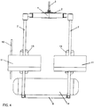
- the illustrated support frame in the form of a three-dimensional frame arrangement is formed in this embodiment in the upper region by crosswise associated telescoping individual frame parts 1, which are connected at the intersection by a connecting element 2, on which an on-board lifting device, for example in the form of a cable 3, attacks.
- the frame assembly is in each case formed frontally by U-shaped associated frame parts to form a receiving opening 5 by a base strut 6 and vertical support 7.
- the base struts 6 each end face are connected via a telescopic connecting strut 8.
- the base struts 6 are slidably disposed on guides 9 of the vertical struts 7.
- the receiving opening 5 is partially closed by a net 10.
- the vertical struts 7 of the arrangement also each receive containers 11, which are designed as floats and / or ballast tanks and can be filled according to the present requirements. Thus, if necessary, the arrangement can be lowered or center of gravity positions of an associated watercraft 12 can be adjusted.
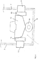
- the vessel 12 is received via the receiving opening 5 and fixed in the recorded position via associated volume variable cushion elements 13.
- the cushion elements 13 are arranged in this embodiment on the containers 11 and can also be arranged directly on the vertical beams 7.
- a volume variable cushion element 14 is additionally arranged on the connecting strut 8 below the watercraft 12.
Landscapes
- Engineering & Computer Science (AREA)
- Mechanical Engineering (AREA)
- Ocean & Marine Engineering (AREA)
- Chemical & Material Sciences (AREA)
- Combustion & Propulsion (AREA)
- Vibration Prevention Devices (AREA)
- Casings For Electric Apparatus (AREA)
- Filling Or Discharging Of Gas Storage Vessels (AREA)
- Cleaning Or Clearing Of The Surface Of Open Water (AREA)
- Refuge Islands, Traffic Blockers, Or Guard Fence (AREA)
- Jib Cranes (AREA)
Description
- Die Erfindung bezieht sich auf eine Vorrichtung für Schiffe zur Aufnahme und zum Aussetzen von Wasserfahrzeugen in Form eines Aufnahmegestells über bordseitige Hebeeinrichtungen, wobei das Wasserfahrzeug über Fixierelemente gehalten wird.
- Bei derartigen Ausbildungen besteht das Problem, eine Handhabung von unterschiedlichen Fahrzeuggrößen und Bootsgeometrien zu ermöglichen. Hierbei ist es bekannt, Aufnahmevorrichtungen über bordseitige Hebeeinrichtungen einzusetzen und das Wasserfahrzeug aufzunehmen bzw. abzusetzen.
- Aus der Druckschrift
EP 0 768 235 A1 ist eine Vorrichtung zum Heben und Senken von Booten im Wasser bekannt, die mindestens einen am Bootskörper angebrachten, als Schwimmkissen ausgebildeten und bei Einwirkung einer ihn bewegenden Kraft entlang der Rumpfoberfläche des Bootes zumindest teilweise unter die Wasseroberfläche geführten Auftriebskörper aufweist. - Die Aufgabe der Erfindung ist es, eine Vorrichtung zur Aufnahme und zum Aussetzen für Wasserfahrzeuge zu schaffen, die zur Handhabung auf einfache Weise an unterschiedliche Wasserfahrzeuge anpassbar und voreinstellbar ist sowie auch die Anpassung an die vorliegenden Schwerpunkte der aufzunehmenden Wasserfahrzeuge gewährleistet.
- Die Lösung dieser Aufgabe erfolgt erfindungsgemäß durch eine Vorrichtung mit den Merkmalen des Anspruchs 1. Die Vorrichtung weist insbesondere ein Aufnahmegestell mit Fixierelementen und mit einem Verbindungselement auf. Das Aufnahmegestell ist durch eine dreidimensionale Rahmenanordnung gebildet, die in Längsrichtung beiderseits des Verbindungselementes für die Hebeeinrichtung über teleskopierende angeordnete Rahmenteile längenveränderlich einstellbar ist und Stirnseiten des Rahmengestells Aufnahmeöffnungen bilden, wobei Vertikalträger der stirnseitigen Rahmenanordnung jeweils Behälter als Auftriebskörper und/oder Ballasttanks aufweisen und zusätzlich Fender in Form steuerbarer volumenveränderlicher Kissenelemente zur Fixierung des aufgenommenen Wasserfahrzeuges angeordnet sind. Zur anpassungsfähigen Einstellung in Längs- und Querrichtung der Vorrichtung ist vorgesehen, dass die Rahmenanordnung im oberen Bereich durch kreuzweise zugeordnete teleskopierende Rahmenteile gebildet ist. Eine untere teleskopierende Verbindungsstrebe ist zwischen unteren Basisstreben von u-förmigen stirnseitigen Rahmenteilen angeordnet, wobei die Basisstreben in Führungen der Vertikalträger bei Verstellung der teleskopierenden kreuzweise angeordneten Rahmenteile verschiebbar sind.
- Hierdurch wird der Vorteil geschaffen, dass das Rahmengestell mit teleskopierenden Rahmenteilen beidseitig bzw. einseitig eine Längeneinstellung zur Anpassung gewährleistet, um den vorliegenden Verhältnissen Rechnung zu tragen. Ferner wird durch die volumenveränderlichen Kissenelemente eine anpassungsfähige Fixierung eines aufgenommenen Wasserfahrzeuges gewährleistet, die sich der Fahrzeuggeometrie anpasst.
- Eine einfache Ausbildung zur Berücksichtigung des Schwerpunktes eines aufgenommenen Wasserfahrzeuges besteht darin, dass die Behälter befüllbare Flüssigkeitsräume zur Schwerpunktsverlagerung aufweisen.
- Ferner wird vorgeschlagen, dass die untere teleskopierende Verbindungsstrebe zusätzlich ein steuerbares volumenveränderbares Kissenelement aufweist.
- Um auch im Unterwasserbereich eine Aufnahme durch die Vorlage zu ermöglichen wird vorgeschlagen, dass die Behälter als Ballasttanks zum Absenken des Aufnahmegestells unter Wasser befüllbar sind.
- Zur Begrenzung des gebildeten Aufnahmeraumes der Vorrichtung wird vorgeschlagen, dass eine Stirnseite der Rahmenanordnung ein Netz zur Lagesicherung eines aufgenommenen Wasserfahrzeuges aufweist.
- Weiterhin wird vorgeschlagen, dass die Volumenveränderung der Kissenelemente durch pneumatische Füllmittel einstellbar ist.
- Eine weitere Ausbildung besteht darin, dass über Steuerungseinheiten die einzelnen Kissenelemente zum Bremsen vor Fixieren und Sichern ansteuerbar sind.
- In den Zeichnungen ist ein Ausführungsbeispiel einer Vorrichtung mit kurzweise teleskopierenden Rahmenteilen im oberen Bereich schematisch dargestellt. Es zeigen:
- Fig. 1 :
- eine perspektivische Darstellung einer Vorrichtung in ihrer ausgefahrener Maximalgröße,
- Fig. 2 :
- eine Darstellung gemäss
Fig. 1 in eingefahrener Minimalgröße, - Fig. 3 :
- eine Seitenansicht gemäss
Fig. 1 , - Fig. 4 :
- eine Seitenansicht gemäss
Fig. 2 und - Fig. 5 :
- eine Teilansicht der Vorrichtung als Vorderansicht mit einem aufgenommenen Wasserfahrzeug
- Das dargestellte Aufnahmegestell in Form einer dreidimensionalen Rahmenanordnung wird in dieser Ausbildung im oberen Bereich durch kreuzweise zugeordnete teleskopierende einzelne Rahmenteile 1 gebildet, die im Kreuzungspunkt durch ein Verbindungselement 2 verbunden sind, an dem eine bordseitige Hebeeinrichtung, beispielsweise in Form eines Seiles 3, angreift. Die Rahmenanordnung wird dabei jeweils stirnseitig durch u-förmig zugeordnete Rahmenteile unter Bildung einer Aufnahmeöffnung 5 durch eine Basisstrebe 6 und Vertikalträger 7 gebildet. Die Basisstreben 6 jeder Stirnseite sind dabei über eine teleskopierbare Verbindungsstrebe 8 verbunden.
- Um eine Verkürzung der Anordnung einseitig oder beidseitig zum Verbindungselement 2 durchzuführen, sind die Basisstreben 6 über Führungen 9 der Vertikalstreben 7 verschiebbar angeordnet.
- Durch die üblicherweise mit Druckluft betriebenen teleskopierenden Rahmenteile 1 und Verbindungsstrebe 8 sind somit eine Veränderung in der Länge und in der Breite des Aufnahmegestells durchführbar. Selbstverständlich ist auch ein Betrieb in hydraulischer Ausbildung möglich. An einer Stirnseite ist die Aufnahmeöffnung 5 durch ein Netz 10 teilweise verschlossen.
- Die Vertikalstreben 7 der Anordnung nehmen ferner jeweils Behälter 11 auf, die als Schwimmkörper und/oder Ballasttanks ausgebildet sind und entsprechend den vorliegenden Anforderungen befüllbar sind. Somit ist die Anordnung gegebenenfalls absenkbar oder es können Schwerpunktslagen eines zugeordneten Wasserfahrzeuges 12 angepasst werden.
- Das Wasserfahrzeug 12 wird über die Aufnahmeöffnung 5 aufgenommen und in der aufgenommenen Position über zugeordnete volumenveränderliche Kissenelemente 13 fixiert. Die Kissenelemente 13 sind in dieser Ausbildung an den Behältern 11 angeordnet und können auch direkt an den Vertikalträgern 7 angeordnet werden. In dieser Ausbildung ist zusätzlich unterhalb des Wasserfahrzeuges 12 ein volumenveränderliches Kissenelement 14 an der Verbindungsstrebe 8 angeordnet.
- Durch diese Ausbildung ist es somit möglich, entsprechend des aufzunehmenden Wasserfahrzeuges 12 eine Voreinstellung über alle Elemente der Rahmenanordnung durchzuführen und gegebenenfalls auch die Behälter 11 zu befüllen. Ferner wird über die einstellbaren Kissenelemente 13, 14 eine Fixierung des aufgenommenen Wasserfahrzeuges 12 vorgenommen, wobei die Kissenelemente 13 während des Aufnahmevorganges des Wasserfahrzeuges 12 als Fender dienen.
Claims (7)
- Vorrichtung für Schiffe zur Aufnahme und zum Aussetzen von Wasserfahrzeugen aufweisend ein Aufnahmegestell mit Fixierelementen, über die ein Wasserfahrzeug im Aufnahmegestell gehalten werden kann,
und mit einem Verbindungselement (2) im obenliegenden Bereich als Angriffspunkt für bordseitige Hebeeinrichtungen ,
wobei das Aufnahmegestell als eine dreidimensionale Rahmenanordnung gebildet ist, dadurch gekennzeichnet,
dass die Rahmenanordnung im oberen Bereich durch kreuzweise zugeordnete teleskopierende Rahmenteile (1), die im Kreuzungspunkt durch das Verbindungselement (2) verbunden sind, gebildet ist,
dass die Rahmenanordnung jeweils stirnseitig durch U-förmige Rahmenteile, die unter Bildung von je einer Aufnahmeöffnung eine untere Basisstrebe (6) und Vertikalträger (7) aufweisen, gebildet ist, wobei eine untere teleskopierende Verbindungsstrebe (8) zwischen den jeweiligen Basisstreben (6)angeordnet ist, und wobei die Basisstreben (6) in Führungen (9) der Vertikalträger (7) bei Verstellung der teleskopierenden kreuzweise angeordneten Rahmenteile (1) verschiebbar sind,
so dass die Rahmenanordnung in Längsrichtung beiderseits des Verbindungselementes (2) längenveränderlich einstellbar ist,
und dass die Vertikalträger (7) jeweils Behälter (11) als Auftriebskörper und/oder Ballasttanks aufweisen und zusätzlich Fender in Form steuerbarer volumenveränderlicher Kissenelemente (13) zur Fixierung des aufgenommenen Wasserfahrzeuges (12) angeordnet sind. - Vorrichtung nach Anspruch 1, dadurch gekennzeichnet, dass die Behälter (11) befüllbare Flüssigkeitsräume zur Schwerpunktsverlagerung aufweisen.
- Vorrichtung nach einem der Ansprüche 1 oder 2, dadurch gekennzeichnet, dass die untere teleskopierende Verbindungsstrebe (8) zusätzlich ein steuerbares volumenveränderbares Kissenelement (14) aufweist.
- Vorrichtung nach einem der Ansprüche 1 bis 3, dadurch gekennzeichnet, dass die Behälter als Ballasttanks zum Absenken des Aufnahmegestells unter Wasser befüllbar sind.
- Vorrichtung nach einem der Ansprüche 1 bis 4, dadurch gekennzeichnet, dass eine Stirnseite der Rahmenanordnung ein Netz (10) zur Lagesicherung eines aufgenommenen Wasserfahrzeuges (12) aufweist.
- Vorrichtung nach einem der Ansprüche 1 bis 5, dadurch gekennzeichnet, dass die Volumenveränderung der Kissenelemente (13, 14) durch pneumatische Füllmittel einstellbar ist.
- Vorrichtung nach einem der Ansprüche 1 bis 6, dadurch gekennzeichnet, dass über Steuerungseinheiten die einzelnen Kissenelemente (13, 14) zum Bremsen vor Fixieren und Sichern ansteuerbar sind.
Applications Claiming Priority (1)
| Application Number | Priority Date | Filing Date | Title |
|---|---|---|---|
| DE102010035952A DE102010035952A1 (de) | 2010-08-31 | 2010-08-31 | Vorrichtung für Schiffe zur Aufnahme und zum Aussetzen von Wasserfahrzeugen |
Publications (2)
| Publication Number | Publication Date |
|---|---|
| EP2423097A1 EP2423097A1 (de) | 2012-02-29 |
| EP2423097B1 true EP2423097B1 (de) | 2017-10-11 |
Family
ID=45001598
Family Applications (1)
| Application Number | Title | Priority Date | Filing Date |
|---|---|---|---|
| EP11006008.4A Active EP2423097B1 (de) | 2010-08-31 | 2011-07-22 | Vorrichtung für Schiffe zur Aufnahme und zum Aussetzen von Wasserfahrzeugen |
Country Status (5)
| Country | Link |
|---|---|
| EP (1) | EP2423097B1 (de) |
| AU (1) | AU2011213906B2 (de) |
| DE (1) | DE102010035952A1 (de) |
| ES (1) | ES2654427T3 (de) |
| ZA (1) | ZA201105332B (de) |
Families Citing this family (5)
| Publication number | Priority date | Publication date | Assignee | Title |
|---|---|---|---|---|
| CN103449300B (zh) * | 2013-09-17 | 2016-03-02 | 无锡美克申思科技有限公司 | 一种吊具 |
| CN104775411B (zh) * | 2015-02-11 | 2017-02-22 | 河海大学 | 水力浮动式升船机及其同步系统侧向倾覆稳定性判别方法 |
| EP3226095A1 (de) | 2016-03-31 | 2017-10-04 | Fraunhofer-Gesellschaft zur Förderung der angewandten Forschung e.V. | System und verfahren zur navigation eines autonom navigierenden tauchkörpers beim einfahren in eine fangstation |
| NO346273B1 (no) * | 2020-06-05 | 2022-05-16 | Nui As | Løfteanordning for livbåter |
| EP3984875B1 (de) * | 2020-10-16 | 2023-10-04 | TotalEnergies OneTech | Stapellauf- und einbergungsplattform für boot, und entsprechendes stapellauf- und einbergungsverfahren |
Family Cites Families (6)
| Publication number | Priority date | Publication date | Assignee | Title |
|---|---|---|---|---|
| FR95287E (fr) * | 1966-10-19 | 1970-08-14 | Peyre Xavier Marie Joseph | Chariot-grue pour bateau de plaisance. |
| US5281077A (en) * | 1993-03-23 | 1994-01-25 | Phillips Gary C | Portable watercraft lift |
| US6076478A (en) * | 1995-10-12 | 2000-06-20 | Siegmann; Goetz | Apparatus for raising and lowering boats |
| EP0768235B1 (de) * | 1995-10-12 | 2000-09-13 | Götz Siegmann | Vorrichtung zum Heben und Senken von Booten im Wasser |
| NL1008152C2 (nl) * | 1998-01-28 | 1999-07-29 | Knijpstra Konstr Bv | Uitschuifbare bootlift. |
| FR2862277B1 (fr) * | 2003-11-18 | 2006-12-01 | Gourlin Jean Marie Joseph | Dispositif permettant le transport le stockage la mise a l'eau et la sortie de l'eau automatise des bateaux de plaisance a voile ou a moteur |
-
2010
- 2010-08-31 DE DE102010035952A patent/DE102010035952A1/de not_active Withdrawn
-
2011
- 2011-07-20 ZA ZA2011/05332A patent/ZA201105332B/en unknown
- 2011-07-22 ES ES11006008.4T patent/ES2654427T3/es active Active
- 2011-07-22 EP EP11006008.4A patent/EP2423097B1/de active Active
- 2011-08-26 AU AU2011213906A patent/AU2011213906B2/en not_active Ceased
Non-Patent Citations (1)
| Title |
|---|
| None * |
Also Published As
| Publication number | Publication date |
|---|---|
| EP2423097A1 (de) | 2012-02-29 |
| DE102010035952A1 (de) | 2012-03-01 |
| ES2654427T3 (es) | 2018-02-13 |
| AU2011213906B2 (en) | 2013-09-05 |
| AU2011213906A1 (en) | 2012-03-15 |
| ZA201105332B (en) | 2012-03-28 |
Similar Documents
| Publication | Publication Date | Title |
|---|---|---|
| DE60208256T2 (de) | Vorrichtung und Verfahren zum Aussetzen und Bergen eines Unterwasserfahrzeuges | |
| EP2423097A1 (de) | Vorrichtung für Schiffe zur Aufnahme und zum Aussetzen von Wasserfahrzeugen | |
| DE2410193A1 (de) | Kopfschutzvorrichtung fuer fahrgaeste von kraftfahrzeugen bei zusammenstoessen | |
| DE10045911B4 (de) | Vorrichtung zum Bergen eines Unterwasserfahrzeugs | |
| DE2124237A1 (de) | Fahrzeug zur Handhabung von Lasten | |
| DE1280078B (de) | Schwimmfahrzeug zur Lagerung von Fluessigkeiten | |
| DE3217034C2 (de) | ||
| DE2641027A1 (de) | Kran zum verladen von umschlagguetern einheitlicher abmessungen | |
| DE4336197A1 (de) | Schleppfahrzeug für Flugzeuge | |
| DE3826274A1 (de) | Einrichtung zum be- und entladen von containern an schiffen | |
| AT15916U1 (de) | Vorrichtung zum Entkernen eines Werkstückes | |
| EP2373519B1 (de) | System zur minensicheren integration von handelsüblichen sitzeinrichtungen | |
| DE102005059430B3 (de) | Verfahren zum Einsatz eines Rettungsgerätes von einem Schiff und von einem Hubschrauber aus für eine oder mehrere im Wasser treibende Personen und Rettungsgerät für eine oder mehrere im Wasser treibende Personen | |
| WO2014110611A1 (de) | Vorrichtung zum festlegen von schwimmkörpern | |
| DE3416375A1 (de) | Vorrichtung zum bergen und transportieren schwerer lasten | |
| EP2000402A1 (de) | Kielvorrichtung für ein Wasserfahrzeug | |
| DE102014000649A1 (de) | Komposit-Rettungsinsel zur Evakuierung, Sicherung und Rettung von schiffbrüchigen Personen | |
| DE102019117268A1 (de) | Installationsanordnung mit Hubinsel und einer Barge und ein Verfahren zum Aufbau der Installationsanordnung | |
| DE102009051986A1 (de) | Vorrichtung zum Umsetzen von Schwerlast von einem Wasserfahrzeug an Land oder umgekehrt | |
| EP2402245B1 (de) | Schiff mit integrierter Aufnahme für Boote | |
| DE102012000444B4 (de) | Flexible Bein-/Fuß-Konstruktion für Hubschiffe, Hubpontons und Hubplattformen | |
| DE102012001866B4 (de) | Abstützsystem für Wasserfahrzeuge zum Abstellen auf einem Untergrund | |
| DE10210818B4 (de) | Haltevorrichtung für Hubschrauber | |
| DE1106357B (de) | Rampe zur Verbindung eines Wasserfahrzeugs, insbesondere eines als Faehre und zur Bildung von Pontonbruecken verwendbaren Amphibienfahrzeugs, mit dem Ufer | |
| DE2145561B2 (de) | Stabilisierungseinrichtung für schwimmende Objekte |
Legal Events
| Date | Code | Title | Description |
|---|---|---|---|
| AK | Designated contracting states |
Kind code of ref document: A1 Designated state(s): AL AT BE BG CH CY CZ DE DK EE ES FI FR GB GR HR HU IE IS IT LI LT LU LV MC MK MT NL NO PL PT RO RS SE SI SK SM TR |
|
| AX | Request for extension of the european patent |
Extension state: BA ME |
|
| PUAI | Public reference made under article 153(3) epc to a published international application that has entered the european phase |
Free format text: ORIGINAL CODE: 0009012 |
|
| 17P | Request for examination filed |
Effective date: 20120307 |
|
| RAP1 | Party data changed (applicant data changed or rights of an application transferred) |
Owner name: THYSSENKRUPP MARINE SYSTEMS GMBH |
|
| 17Q | First examination report despatched |
Effective date: 20160324 |
|
| STAA | Information on the status of an ep patent application or granted ep patent |
Free format text: STATUS: EXAMINATION IS IN PROGRESS |
|
| GRAP | Despatch of communication of intention to grant a patent |
Free format text: ORIGINAL CODE: EPIDOSNIGR1 |
|
| STAA | Information on the status of an ep patent application or granted ep patent |
Free format text: STATUS: GRANT OF PATENT IS INTENDED |
|
| INTG | Intention to grant announced |
Effective date: 20170717 |
|
| GRAS | Grant fee paid |
Free format text: ORIGINAL CODE: EPIDOSNIGR3 |
|
| GRAA | (expected) grant |
Free format text: ORIGINAL CODE: 0009210 |
|
| STAA | Information on the status of an ep patent application or granted ep patent |
Free format text: STATUS: THE PATENT HAS BEEN GRANTED |
|
| RIN1 | Information on inventor provided before grant (corrected) |
Inventor name: POPALL, CHRISTIAN Inventor name: BALLE, JENS |
|
| AK | Designated contracting states |
Kind code of ref document: B1 Designated state(s): AL AT BE BG CH CY CZ DE DK EE ES FI FR GB GR HR HU IE IS IT LI LT LU LV MC MK MT NL NO PL PT RO RS SE SI SK SM TR |
|
| REG | Reference to a national code |
Ref country code: GB Ref legal event code: FG4D Free format text: NOT ENGLISH |
|
| REG | Reference to a national code |
Ref country code: CH Ref legal event code: EP |
|
| REG | Reference to a national code |
Ref country code: IE Ref legal event code: FG4D Free format text: LANGUAGE OF EP DOCUMENT: GERMAN |
|
| REG | Reference to a national code |
Ref country code: AT Ref legal event code: REF Ref document number: 935767 Country of ref document: AT Kind code of ref document: T Effective date: 20171115 |
|
| REG | Reference to a national code |
Ref country code: DE Ref legal event code: R096 Ref document number: 502011013108 Country of ref document: DE Ref country code: DE Ref legal event code: R084 Ref document number: 502011013108 Country of ref document: DE |
|
| REG | Reference to a national code |
Ref country code: ES Ref legal event code: FG2A Ref document number: 2654427 Country of ref document: ES Kind code of ref document: T3 Effective date: 20180213 |
|
| REG | Reference to a national code |
Ref country code: NL Ref legal event code: MP Effective date: 20171011 |
|
| REG | Reference to a national code |
Ref country code: LT Ref legal event code: MG4D |
|
| PG25 | Lapsed in a contracting state [announced via postgrant information from national office to epo] |
Ref country code: NL Free format text: LAPSE BECAUSE OF FAILURE TO SUBMIT A TRANSLATION OF THE DESCRIPTION OR TO PAY THE FEE WITHIN THE PRESCRIBED TIME-LIMIT Effective date: 20171011 |
|
| PG25 | Lapsed in a contracting state [announced via postgrant information from national office to epo] |
Ref country code: FI Free format text: LAPSE BECAUSE OF FAILURE TO SUBMIT A TRANSLATION OF THE DESCRIPTION OR TO PAY THE FEE WITHIN THE PRESCRIBED TIME-LIMIT Effective date: 20171011 Ref country code: LT Free format text: LAPSE BECAUSE OF FAILURE TO SUBMIT A TRANSLATION OF THE DESCRIPTION OR TO PAY THE FEE WITHIN THE PRESCRIBED TIME-LIMIT Effective date: 20171011 Ref country code: SE Free format text: LAPSE BECAUSE OF FAILURE TO SUBMIT A TRANSLATION OF THE DESCRIPTION OR TO PAY THE FEE WITHIN THE PRESCRIBED TIME-LIMIT Effective date: 20171011 Ref country code: NO Free format text: LAPSE BECAUSE OF FAILURE TO SUBMIT A TRANSLATION OF THE DESCRIPTION OR TO PAY THE FEE WITHIN THE PRESCRIBED TIME-LIMIT Effective date: 20180111 |
|
| PG25 | Lapsed in a contracting state [announced via postgrant information from national office to epo] |
Ref country code: BG Free format text: LAPSE BECAUSE OF FAILURE TO SUBMIT A TRANSLATION OF THE DESCRIPTION OR TO PAY THE FEE WITHIN THE PRESCRIBED TIME-LIMIT Effective date: 20180111 Ref country code: HR Free format text: LAPSE BECAUSE OF FAILURE TO SUBMIT A TRANSLATION OF THE DESCRIPTION OR TO PAY THE FEE WITHIN THE PRESCRIBED TIME-LIMIT Effective date: 20171011 Ref country code: LV Free format text: LAPSE BECAUSE OF FAILURE TO SUBMIT A TRANSLATION OF THE DESCRIPTION OR TO PAY THE FEE WITHIN THE PRESCRIBED TIME-LIMIT Effective date: 20171011 Ref country code: RS Free format text: LAPSE BECAUSE OF FAILURE TO SUBMIT A TRANSLATION OF THE DESCRIPTION OR TO PAY THE FEE WITHIN THE PRESCRIBED TIME-LIMIT Effective date: 20171011 Ref country code: GR Free format text: LAPSE BECAUSE OF FAILURE TO SUBMIT A TRANSLATION OF THE DESCRIPTION OR TO PAY THE FEE WITHIN THE PRESCRIBED TIME-LIMIT Effective date: 20180112 Ref country code: IS Free format text: LAPSE BECAUSE OF FAILURE TO SUBMIT A TRANSLATION OF THE DESCRIPTION OR TO PAY THE FEE WITHIN THE PRESCRIBED TIME-LIMIT Effective date: 20180211 |
|
| REG | Reference to a national code |
Ref country code: DE Ref legal event code: R097 Ref document number: 502011013108 Country of ref document: DE |
|
| REG | Reference to a national code |
Ref country code: FR Ref legal event code: PLFP Year of fee payment: 8 |
|
| PG25 | Lapsed in a contracting state [announced via postgrant information from national office to epo] |
Ref country code: DK Free format text: LAPSE BECAUSE OF FAILURE TO SUBMIT A TRANSLATION OF THE DESCRIPTION OR TO PAY THE FEE WITHIN THE PRESCRIBED TIME-LIMIT Effective date: 20171011 Ref country code: SK Free format text: LAPSE BECAUSE OF FAILURE TO SUBMIT A TRANSLATION OF THE DESCRIPTION OR TO PAY THE FEE WITHIN THE PRESCRIBED TIME-LIMIT Effective date: 20171011 Ref country code: EE Free format text: LAPSE BECAUSE OF FAILURE TO SUBMIT A TRANSLATION OF THE DESCRIPTION OR TO PAY THE FEE WITHIN THE PRESCRIBED TIME-LIMIT Effective date: 20171011 Ref country code: CZ Free format text: LAPSE BECAUSE OF FAILURE TO SUBMIT A TRANSLATION OF THE DESCRIPTION OR TO PAY THE FEE WITHIN THE PRESCRIBED TIME-LIMIT Effective date: 20171011 |
|
| PLBE | No opposition filed within time limit |
Free format text: ORIGINAL CODE: 0009261 |
|
| STAA | Information on the status of an ep patent application or granted ep patent |
Free format text: STATUS: NO OPPOSITION FILED WITHIN TIME LIMIT |
|
| PG25 | Lapsed in a contracting state [announced via postgrant information from national office to epo] |
Ref country code: PL Free format text: LAPSE BECAUSE OF FAILURE TO SUBMIT A TRANSLATION OF THE DESCRIPTION OR TO PAY THE FEE WITHIN THE PRESCRIBED TIME-LIMIT Effective date: 20171011 Ref country code: SM Free format text: LAPSE BECAUSE OF FAILURE TO SUBMIT A TRANSLATION OF THE DESCRIPTION OR TO PAY THE FEE WITHIN THE PRESCRIBED TIME-LIMIT Effective date: 20171011 Ref country code: RO Free format text: LAPSE BECAUSE OF FAILURE TO SUBMIT A TRANSLATION OF THE DESCRIPTION OR TO PAY THE FEE WITHIN THE PRESCRIBED TIME-LIMIT Effective date: 20171011 |
|
| 26N | No opposition filed |
Effective date: 20180712 |
|
| PG25 | Lapsed in a contracting state [announced via postgrant information from national office to epo] |
Ref country code: MT Free format text: LAPSE BECAUSE OF FAILURE TO SUBMIT A TRANSLATION OF THE DESCRIPTION OR TO PAY THE FEE WITHIN THE PRESCRIBED TIME-LIMIT Effective date: 20171011 |
|
| PG25 | Lapsed in a contracting state [announced via postgrant information from national office to epo] |
Ref country code: SI Free format text: LAPSE BECAUSE OF FAILURE TO SUBMIT A TRANSLATION OF THE DESCRIPTION OR TO PAY THE FEE WITHIN THE PRESCRIBED TIME-LIMIT Effective date: 20171011 |
|
| REG | Reference to a national code |
Ref country code: CH Ref legal event code: PL |
|
| PG25 | Lapsed in a contracting state [announced via postgrant information from national office to epo] |
Ref country code: MC Free format text: LAPSE BECAUSE OF FAILURE TO SUBMIT A TRANSLATION OF THE DESCRIPTION OR TO PAY THE FEE WITHIN THE PRESCRIBED TIME-LIMIT Effective date: 20171011 Ref country code: LU Free format text: LAPSE BECAUSE OF NON-PAYMENT OF DUE FEES Effective date: 20180722 |
|
| REG | Reference to a national code |
Ref country code: BE Ref legal event code: MM Effective date: 20180731 |
|
| REG | Reference to a national code |
Ref country code: IE Ref legal event code: MM4A |
|
| PG25 | Lapsed in a contracting state [announced via postgrant information from national office to epo] |
Ref country code: IE Free format text: LAPSE BECAUSE OF NON-PAYMENT OF DUE FEES Effective date: 20180722 Ref country code: CH Free format text: LAPSE BECAUSE OF NON-PAYMENT OF DUE FEES Effective date: 20180731 Ref country code: LI Free format text: LAPSE BECAUSE OF NON-PAYMENT OF DUE FEES Effective date: 20180731 |
|
| PG25 | Lapsed in a contracting state [announced via postgrant information from national office to epo] |
Ref country code: BE Free format text: LAPSE BECAUSE OF NON-PAYMENT OF DUE FEES Effective date: 20180731 |
|
| REG | Reference to a national code |
Ref country code: AT Ref legal event code: MM01 Ref document number: 935767 Country of ref document: AT Kind code of ref document: T Effective date: 20180722 |
|
| REG | Reference to a national code |
Ref country code: DE Ref legal event code: R081 Ref document number: 502011013108 Country of ref document: DE Owner name: THYSSENKRUPP MARINE SYSTEMS GMBH, DE Free format text: FORMER OWNER: THYSSENKRUPP MARINE SYSTEMS GMBH, 24143 KIEL, DE |
|
| PG25 | Lapsed in a contracting state [announced via postgrant information from national office to epo] |
Ref country code: AT Free format text: LAPSE BECAUSE OF NON-PAYMENT OF DUE FEES Effective date: 20180722 |
|
| PG25 | Lapsed in a contracting state [announced via postgrant information from national office to epo] |
Ref country code: TR Free format text: LAPSE BECAUSE OF FAILURE TO SUBMIT A TRANSLATION OF THE DESCRIPTION OR TO PAY THE FEE WITHIN THE PRESCRIBED TIME-LIMIT Effective date: 20171011 |
|
| PG25 | Lapsed in a contracting state [announced via postgrant information from national office to epo] |
Ref country code: PT Free format text: LAPSE BECAUSE OF FAILURE TO SUBMIT A TRANSLATION OF THE DESCRIPTION OR TO PAY THE FEE WITHIN THE PRESCRIBED TIME-LIMIT Effective date: 20171011 Ref country code: HU Free format text: LAPSE BECAUSE OF FAILURE TO SUBMIT A TRANSLATION OF THE DESCRIPTION OR TO PAY THE FEE WITHIN THE PRESCRIBED TIME-LIMIT; INVALID AB INITIO Effective date: 20110722 |
|
| PG25 | Lapsed in a contracting state [announced via postgrant information from national office to epo] |
Ref country code: MK Free format text: LAPSE BECAUSE OF NON-PAYMENT OF DUE FEES Effective date: 20171011 Ref country code: CY Free format text: LAPSE BECAUSE OF FAILURE TO SUBMIT A TRANSLATION OF THE DESCRIPTION OR TO PAY THE FEE WITHIN THE PRESCRIBED TIME-LIMIT Effective date: 20171011 |
|
| PG25 | Lapsed in a contracting state [announced via postgrant information from national office to epo] |
Ref country code: AL Free format text: LAPSE BECAUSE OF FAILURE TO SUBMIT A TRANSLATION OF THE DESCRIPTION OR TO PAY THE FEE WITHIN THE PRESCRIBED TIME-LIMIT Effective date: 20171011 |
|
| PGFP | Annual fee paid to national office [announced via postgrant information from national office to epo] |
Ref country code: DE Payment date: 20240719 Year of fee payment: 14 |
|
| PGFP | Annual fee paid to national office [announced via postgrant information from national office to epo] |
Ref country code: GB Payment date: 20240723 Year of fee payment: 14 |
|
| PGFP | Annual fee paid to national office [announced via postgrant information from national office to epo] |
Ref country code: FR Payment date: 20240730 Year of fee payment: 14 |
|
| PGFP | Annual fee paid to national office [announced via postgrant information from national office to epo] |
Ref country code: ES Payment date: 20240828 Year of fee payment: 14 |
|
| PGFP | Annual fee paid to national office [announced via postgrant information from national office to epo] |
Ref country code: IT Payment date: 20240725 Year of fee payment: 14 |
|
| REG | Reference to a national code |
Ref country code: DE Ref legal event code: R119 Ref document number: 502011013108 Country of ref document: DE |
|
| GBPC | Gb: european patent ceased through non-payment of renewal fee |
Effective date: 20250722 |
|
| PG25 | Lapsed in a contracting state [announced via postgrant information from national office to epo] |
Ref country code: GB Free format text: LAPSE BECAUSE OF NON-PAYMENT OF DUE FEES Effective date: 20250722 |
|
| PG25 | Lapsed in a contracting state [announced via postgrant information from national office to epo] |
Ref country code: DE Free format text: LAPSE BECAUSE OF NON-PAYMENT OF DUE FEES Effective date: 20260203 |
|
| PG25 | Lapsed in a contracting state [announced via postgrant information from national office to epo] |
Ref country code: FR Free format text: LAPSE BECAUSE OF NON-PAYMENT OF DUE FEES Effective date: 20250731 |