EP3984875B1 - Stapellauf- und einbergungsplattform für boot, und entsprechendes stapellauf- und einbergungsverfahren - Google Patents
Stapellauf- und einbergungsplattform für boot, und entsprechendes stapellauf- und einbergungsverfahren Download PDFInfo
- Publication number
- EP3984875B1 EP3984875B1 EP20306234.4A EP20306234A EP3984875B1 EP 3984875 B1 EP3984875 B1 EP 3984875B1 EP 20306234 A EP20306234 A EP 20306234A EP 3984875 B1 EP3984875 B1 EP 3984875B1
- Authority
- EP
- European Patent Office
- Prior art keywords
- boat
- launch
- recovery platform
- frame
- platform
- Prior art date
- Legal status (The legal status is an assumption and is not a legal conclusion. Google has not performed a legal analysis and makes no representation as to the accuracy of the status listed.)
- Active
Links
Images


Classifications
-
- B—PERFORMING OPERATIONS; TRANSPORTING
- B63—SHIPS OR OTHER WATERBORNE VESSELS; RELATED EQUIPMENT
- B63C—LAUNCHING, HAULING-OUT, OR DRY-DOCKING OF VESSELS; LIFE-SAVING IN WATER; EQUIPMENT FOR DWELLING OR WORKING UNDER WATER; MEANS FOR SALVAGING OR SEARCHING FOR UNDERWATER OBJECTS
- B63C3/00—Launching or hauling-out by landborne slipways; Slipways
- B63C3/10—Launching or hauling-out by landborne slipways; Slipways using releasing devices
-
- B—PERFORMING OPERATIONS; TRANSPORTING
- B63—SHIPS OR OTHER WATERBORNE VESSELS; RELATED EQUIPMENT
- B63B—SHIPS OR OTHER WATERBORNE VESSELS; EQUIPMENT FOR SHIPPING
- B63B27/00—Arrangement of ship-based loading or unloading equipment for cargo or passengers
- B63B27/36—Arrangement of ship-based loading or unloading equipment for floating cargo
-
- B—PERFORMING OPERATIONS; TRANSPORTING
- B63—SHIPS OR OTHER WATERBORNE VESSELS; RELATED EQUIPMENT
- B63B—SHIPS OR OTHER WATERBORNE VESSELS; EQUIPMENT FOR SHIPPING
- B63B23/00—Equipment for handling lifeboats or the like
- B63B23/30—Devices for guiding boats to water surface
- B63B23/32—Rigid guides, e.g. having arms pivoted near waterline
-
- B—PERFORMING OPERATIONS; TRANSPORTING
- B63—SHIPS OR OTHER WATERBORNE VESSELS; RELATED EQUIPMENT
- B63B—SHIPS OR OTHER WATERBORNE VESSELS; EQUIPMENT FOR SHIPPING
- B63B27/00—Arrangement of ship-based loading or unloading equipment for cargo or passengers
- B63B27/16—Arrangement of ship-based loading or unloading equipment for cargo or passengers of lifts or hoists
-
- B—PERFORMING OPERATIONS; TRANSPORTING
- B63—SHIPS OR OTHER WATERBORNE VESSELS; RELATED EQUIPMENT
- B63C—LAUNCHING, HAULING-OUT, OR DRY-DOCKING OF VESSELS; LIFE-SAVING IN WATER; EQUIPMENT FOR DWELLING OR WORKING UNDER WATER; MEANS FOR SALVAGING OR SEARCHING FOR UNDERWATER OBJECTS
- B63C3/00—Launching or hauling-out by landborne slipways; Slipways
- B63C3/06—Launching or hauling-out by landborne slipways; Slipways by vertical movement of vessel, i.e. by crane
-
- B—PERFORMING OPERATIONS; TRANSPORTING
- B63—SHIPS OR OTHER WATERBORNE VESSELS; RELATED EQUIPMENT
- B63B—SHIPS OR OTHER WATERBORNE VESSELS; EQUIPMENT FOR SHIPPING
- B63B27/00—Arrangement of ship-based loading or unloading equipment for cargo or passengers
- B63B27/16—Arrangement of ship-based loading or unloading equipment for cargo or passengers of lifts or hoists
- B63B2027/165—Deployment or recovery of underwater vehicles using lifts or hoists
Definitions
- the present invention relates to the field of transport and handling of floating devices. More particularly, the invention relates to the field of assistance in launching and recovering a ship. In particular, it relates to a boat launch and recovery platform. The invention further relates to a method for launching and removing from the water a platform for launching and recovering a boat usable with or without crew on board.
- the exploration of marine territories involves more and more small boats that can be launched from a larger vessel or from a fixed or floating marine construction.
- unmanned surface vehicles are currently being developed for a variety of applications where manned operations can put the lives of occupants at risk.
- the question then arises of the autonomous recovery of these unmanned surface vehicles or even their storage afloat and off-float.
- launch and subsequent recovery options for these vehicles have stagnated.
- the launching of boats generally uses launch and recovery systems.
- ships or marine construction use davits or cranes to deploy boats using cables, pulleys, tackles and hooks.
- davits can connect to cables attached to each end of the lifeboat and raise a lifeboat afloat.
- such a maneuver takes time and can be dangerous.
- Rigid inflatable boats are typically deployed and recovered by a cable attached to a central pivot point of the inflatable boat and manipulated by a crane positioned on the ship or marine construction.
- a crane positioned on the ship or marine construction.
- Ramps are generally associated with ships and cannot be easily adapted to marine constructions with platforms at an altitude much higher than sea level. In addition, ramps are not suitable for long-term storage of the boat whether in the water or out of the water.
- the invention aims to remedy the drawbacks of the prior art.
- the invention aims to provide a platform for launching and recovering a boat providing an anchor point at sea allowing the mooring of a boat, to facilitate its recovery by a motorized vehicle of larger size. scale while allowing, once on land, the boat to be stored.
- the invention further aims to propose a method for launching and removing the water from a boat included in the launch and recovery platform according to the invention.
- the launch and recovery platform allows the boat to be stored on land or in the ship or marine construction from which it is launched. Above the water, the frame can be covered with a cover to create a protective shelter for the boat and to accommodate maintenance operations.
- the latter may optionally include one or more of the following features, alone or in combination:
- the invention also relates to a use of a launch and recovery platform according to the invention as an autonomous receptacle of a boat.
- the boat Once afloat, the boat will be able to set off quickly in a controlled manner without human presence on the boat or on the reception structure.
- the boat is supported by gravity on the front of the reception structure without the risk of sliding backwards if the locking cylinders open by accident
- set of profiles " or " profiles” corresponds to structural elements such as beams or bars cut according to predetermined dimensions and serving as a base in the context of mechanical constructions requiring assembly complex.
- enclosure within the meaning of the invention any structure adapted to allow the reception of a boat within the structure.
- entrance is mentioned in connection with the enclosure or more generally with the launch and recovery platform, we mean an opening allowing the passage of at least part of the boat inside the frame.
- frame within the meaning of the invention corresponds to an assembly of parts or elements, such as profiles for example, forming a structure adapted to accommodate and support a floating vehicle.
- translation within the meaning of the invention, is meant a movement of a solid, for which each point of the solid moves along the same trajectory and at the same speed.
- a horizontal translation relative to another object could for example correspond to a movement parallel to said other object between a first position and a second position.
- a vertical translation within the meaning of the invention, may correspond to a translation movement of a solid, for which each point of the solid moves perpendicular to another object, between a first position and a second position.
- Coupled within the meaning of the invention, is meant connected, directly or indirectly, with one or more intermediate elements. Two elements can be mechanically coupled.
- removable within the meaning of the invention, corresponds to the ability to be detached, removed or dismantled easily without having to destroy means of fixing, either because there is no means of fixing, or because the fixing means are easily and quickly removable (for example a notch, a screw, a tab, a lug, a clip system).
- removable it must be understood that the object is not fixed by welding or by another means not intended to allow the object to be detached.
- irremovable we must understand that the object is fixed by welding or by another means not intended to allow the object to be detached.
- ber we mean a structure supporting a boat. This can in particular correspond to a metal frame equipped with skids on which a boat rests.
- Boat means any floating vehicle, whether autonomous or not, and equipped with a hull and/or floats.
- the inventors therefore developed a new launch and recovery platform for boats.
- This platform can allow the deployment and recovery of a surface vehicle without direct human intervention but also serve as a mooring point for the surface vehicle once the platform is anchored at sea, moored to a quay or once on land. surface vehicle storage device.
- This platform has the particularity of having a floating floor intended to at least partially support the boat when the platform is afloat.
- This floating floor is advantageously arranged within the platform so as to have at least one degree of freedom of vertical movement relative to the frame. This helps reduce the effect of swell on the platform, particularly when it supports the boat afloat.
- the inventors have also developed a system for securing the boat, particularly for use when the boat is positioned within the frame.
- the invention relates to a launch and recovery platform 1 for a boat.
- a launch and recovery platform 1 for a boat comprises a frame 10, flotation means 20 and a floating floor 30.
- the frame 10 is arranged so as to be able to accommodate a boat 2 (eg at least part of the boat 2), or more generally any floating vehicle, motorized or not, with or without a pilot.
- the frame is advantageously arranged to accommodate only part of the boat 2 leaving part of the boat protruding from the frame.
- the platform is arranged so that a part of the boat, such as for example propellers positioned at the rear of the boat, is located outside the frame.
- the frame 10 comprises for example a set of profiles or any other structural element capable of forming such a frame and in particular an enclosure capable of accommodating a boat.
- the enclosure will include an opening through which a boat can pass to accommodate itself at least partly within the frame. This entrance will preferably be on one side of the frame so that the boat can enter the enclosure when it is floating on the water.
- the armature may include several entrances with for example an entrance from the upper face and an entrance on the side or the rear face.
- the frame has a single entry on the rear face corresponding to the entry point of the boat into the frame, said entry preferably being made thanks to the thrust of the engines.
- the motors as illustrated in the figures can remain outside the frame, pointing upwards when platform 1 is afloat and downwards when the frame is afloat.
- the profiles or other structural elements are advantageously designed from materials having mechanical characteristics adapted to support the load of the launch and recovery platform 1 as well as the boat 2 that said platform is intended to accommodate.
- the profiles forming the frame 10 can be mainly made of metal or a metal alloy.
- the profiles forming the frame 10 may be made of iron or an iron alloy such as steel. Titanium or aluminum can also be used, depending on the strength required.
- the profiles or other structural elements could be made of composite materials (reinforcement and polymers) or polymers. It may also be desirable for the material of the frame 10 to be resistant to corrosion or protected by painting and/or cathodic protection since the platform 1 is designed to remain in water for long periods (> 1 month).
- the profiles can have a thickness of at least 2 millimeters (mm), and can reach a thickness of 4mm, 6mm, 8mm or more depending on the desired mechanical characteristics.
- the profiles can also have a square geometry and be hollow.
- the steel used for forming the profiles can for example correspond to S235 or even S275 steel in order to meet the standards of the offshore sector, in particular the ISO EN 10855 standard and the DNV-GL 2.7-1 standard.
- the set of profiles of the frame 10 may comprise at least one transverse beam and/or at least one rigid longitudinal beam 101 forming the upper face of the frame 10.
- Said rigid transverse and longitudinal beam 101 may advantageously correspond to metal steel beams of type IPN 120 (for “i” with normal profile 120).
- the upper face comprises two rigid transverse beams 101 respectively fixed to the ends of two longitudinal beams 101, said longitudinal beams 101 being parallel to each other.
- the upper face may comprise at least two, preferably at least four lifting rings 110 intended to cooperate with a lifting means.
- each of the rigid transverse or longitudinal beams 101 may comprise two lifting rings 110 positioned respectively at the ends of said rigid transverse or longitudinal beams 101.
- a lifting ring 110 can be made of S235 steel and have an orifice adapted to allow coupling with a hooking device.
- a lifting ring 110 can correspond to a lifting yoke shackles made mainly of S355 steel, a metal cable sling made of high-strength galvanized steel S355 or even a triple ring made mainly of S355 steel.
- the frame of the platform 1 according to the invention will also include a support floor 11.
- a support floor is intended to support a floating floor integrated into the platform 1 and which will be described below.
- the support floor 11 may be formed from a plurality of profiles 106. Alternatively, it may be formed from one or more plates assembled so as to form a support for a floating floor.
- the support floor 11 can form a cradle comprising a plurality of skids 108 intended to support the boat 2 when said launch and recovery platform 1 is in the out-of-water position.
- the support floor 11 can for example comprise at least four skates positioned so as to support the boat 2 above the floating floor when the platform 1 is out of the water.
- the skates 108 can be associated with telescopic arms so as to be adapted to any type of boat.
- the telescopic arms may or may not be motorized and remote controlled.
- the skates 108 may be equipped with bearings.
- the support floor 11 could be connected to a lower base 12 of the frame 10. It could for example be connected via profiles 106 or spacers to the lower base 12. In order to increase the mechanical strength of the frame, it may include crosspieces between the support floor 11 and the lower base 12.
- the crosspieces or spacers 106 may be rigid metal tubes welded together.
- the support floor 11 and more generally the frame 10 may be capable of supporting a significant weight, for example more than 2 tons, preferably more than 10 tons, more preferably more than 20 tons, for example around 25 tons.
- the support floor 11 can form the lower base 12 of the frame 10.
- the lower base 12 corresponds to the lower face of the frame 10. This is the face on which the platform rests when it is out of water. .
- the launch and recovery platform 1 also includes flotation means 20.
- launch and recovery platform 1 will be able to remain at sea for a long time.
- the design of the platform can adapt to different lengths of vessels and the flotation means 20 help to maintain a parallel relationship between the upper face of the frame 10 and the waterline.
- the flotation means 20 allow the platform to float on the water but must also, in combination with the floating floor, ensure stabilization at sea of the recovered boat.
- the flotation means 20 can include any material floating in the water.
- the flotation means 20 are composed of a polymeric material such as various natural and synthetic rubbers, or open or closed cell foams.
- the flotation means 20 may be solid or inflatable.
- the flotation means 20 comprise expanded foam such as expanded polystyrene foam (EPS).
- EPS expanded polystyrene foam
- the flotation means 20 will for example be of longitudinal shape.
- the flotation means 20 can be dimensioned such that when afloat, part of the flotation means 20 extends above the surface of the water.
- the flotation means 20 may in particular take the form of at least two floats 72, preferably lateral.
- the flotation means 20 may consist of two cylindrical plastic floats filled with expanded polystyrene foam (EPS).
- EPS expanded polystyrene foam
- the flotation means 20 can be permanently or removably fixed to the frame 10.
- the reinforcement may include profiles 110 arranged so as to be able to at least partially crimp the flotation means 20.
- the launch and recovery platform 1 also includes a floating floor 30 illustrated in particular in the figure 1 .
- the floating floor 30 is essential. It will be arranged within platform 1 so as to support, at least partially, boat 2 when platform 1 is afloat. Advantageously it will support the front part of the boat 2 and will have a degree of freedom of vertical movement relative to the frame 10 allowing it to float freely on the surface of the water independently of the vertical movements of the frame 10.
- a floating floor 30 will be coupled to the frame 10 so as to be movable in vertical translation relative to the frame, such as for example relative to the support floor 11 or to the lower base 12.
- the floating floor 30 can also be coupled to the frame 10 so as to be additionally movable in horizontal translation, in particular relative to the support floor 11. This is particularly visible at the figure 1 .
- the floating floor 30 is coupled to the frame 10 by an attachment means 34 which can take the form of a connecting ring 34 arranged to enclose at least one guide bar 109 fixed to the frame 10.
- the floating floor 30 is advantageously equipped with an attachment means 34 allowing freedom of movement relative to the frame 10.
- the horizontal translation movements of the floating floor can be limited by a system securing 3 of the boat 2.
- the attachment means 34 according to figure 1 can have any form of opening at the level of the connecting ring, for example an opening in the shape of an ellipse or parallelepiped.
- the attachment means 34 according to the figure 1 presents at the level of the connecting ring an opening in the shape of a parallelepiped also allowing horizontal translation of the floating floor 30 relative to the support floor 11 or to the lower base 12.
- the floating floor 30 also has little transverse movement relative to the support floor 11 or at the lower base 12.
- the floating floor 30 can also be coupled to the frame 10 by means of a slide-type connection, a ring equipped with a polymer pad (eg high-density or medium-density polyethylene, polyamide) sliding on a vertical structure acting as a rail, or a combination of rings and bars attached to the frame.
- a polymer pad eg high-density or medium-density polyethylene, polyamide
- the floating floor 30 will be coupled to the frame 10 by means of a combination of rings, preferably fixed to the floating floor and bars, preferably fixed to the frame. This embodiment makes it possible to reduce the clearances to improve the precision of the guidance.
- the floating floor 30 is intended to support the boat 2 at least partially at sea. Thus, it has dimensions adapted to this function. In particular, it may have a surface in contact with water greater than 2 m 2 , preferably greater than 10 m 2 , more preferably greater than 15 m 2 , even more preferably greater than 25 m 2 .
- the floating floor 30 may have a thickness greater than 10 cm, preferably greater than 20 cm, more preferably greater than 30 cm.
- the floating floor 30 is composed of a polymeric material such as various natural and synthetic rubbers, or open or closed cell foams.
- the floating floor 30 is formed from floating modular blocks. These blocks can be fitted into each other so as to form the floating floor 30.
- the floating floor can be formed from a wood-epoxy composite floor or from a roto-molded plastic shape.
- the floating floor 30 can form a planar structure. However, preferably, it forms a structure comprising at least two planes and more preferably several planes so as to at least partially follow the shape of the hull of the boat 2. In addition, it may include openings allowing the passage of bars verticals involved in the vertical translation of the floating floor or allowing passage of the skids 108 associated with the cradle.
- the floating floor 30 may include a plurality of openings arranged to allow the positioning of the plurality of skates 108 on the boat 2 when said launch and recovery platform 1 is in the out-of-water position.
- the launch and recovery platform 1 is advantageously arranged to move from a configuration in which the floating floor 30 rests on the support floor 11 when the launch and recovery platform 1 is out of the water , to a configuration in which the floating floor 30 floats on the surface S1 of the water when the launch and recovery platform 1 is afloat.
- launch and recovery platform 1 is out of flow. Gravity therefore induces the positioning of the floating floor 30 on the support floor 11.
- the boat for its part rests on the floating floor 30.
- the boat 2 could rest on the runners 108.
- the launch and recovery platform 1 may include a lower base 12, distinct from the support floor 11.
- This lower base 12 may be formed of profiles. It is part of the frame 10 and it advantageously constitutes the part of the frame 10 resting on the ground (e.g. a quay or a ship platform).
- the support floor 11 will advantageously present a plane forming, with respect to the lower base 12, an angle ⁇ greater than or equal to 10°, preferably greater than or equal to 15°, more preferably greater than or equal to 20°, even more preferably greater than or equal to 25°.
- This angle ⁇ will generally be less than 60°.
- the angle may be between 10° and 45°, preferably between 20° and 30°, even more preferably between 25° and 35°.
- the angle is preferably calculated between the longitudinal axis of the floating floor and a plane formed by the lower base 12.
- the boat 2 may rest at least partly on the floating floor 30 itself resting on the support floor 11.
- the support floor 11 may form a cradle comprising a plurality of skids 108.
- This embodiment was particularly illustrated in figure 2 And 3 .
- the floating floor 30 will rest on the support floor 11 but the boat 2 will not rest on the floating floor 30 but on the skids 108 associated with the cradle formed by the support floor 11.
- This has the advantage of maintaining a position inclined towards the front of the boat 2 during its storage out of water but also to preserve the mechanical properties of the floating floor given that it will not be crushed by the boat 2.
- the boat 2 hosted by the launch and recovery platform 1 will be positioned in a safety position in which the engines of the boat 2 will be raised allowing easier inspection and less risk of tipping or damage during handling the loaded platform 1.
- the floating floor 30 when the launch and recovery platform 1 is floated, the floating floor 30 will be arranged so as to float on the surface of the water S1.
- the boat will be slightly inclined and at least part of the propellers of the engine(s) can be submerged.
- the platform allows for securing outside the water, it also allows, without additional manipulation, to place the boat in a configuration in which it can move away autonomously from the platform when in the water.
- the floating floor 30 is advantageously arranged so as to comprise, in the afloat position, a plane forming an angle ⁇ of at most 30° with the surface of the water S1.
- a plane forming an angle ⁇ of at most 30° with the surface of the water S1.
- the floating floor 30 may be arranged so as to comprise, in the afloat position, a plane forming an angle ⁇ of at least 10° relative to the support floor 11 of the frame 10.
- the angle ⁇ will be at least 20°, preferably at least 25°.
- the platform 1 allows the boat to tilt from a position out of the flow inclined towards the front to a position with the flow inclined towards the rear and this without the aid of cylinders or other motorized systems.
- the angle is preferably calculated between the longitudinal axis of the floating floor 30 and the longitudinal axis of the support floor 11.
- the support floor 11 may form the lower base 12 of the launch and recovery platform 1.
- the support floor 11 may include the plurality of pads 108. These pads 108 may be arranged so that the longitudinal axis of the boat 2 supported by said plurality of pads 108 forms an angle ⁇ relative to the support floor 11 greater than or equal to 10°, preferably greater than or equal to 15°, more preferably greater than or equal to 20°, even more preferably greater than or equal to 25°.
- This angle ⁇ will generally be less than 60°.
- the angle may be between 10° and 40°, preferably between 20° and 35°, even more preferably between 25° and 30°.
- the angle is preferably calculated between the longitudinal axis of the floating floor and a plane formed by the lower base 12.
- the plurality of skates 108 may have lengths selected so as to induce such an angle and therefore an inclination of the boat forward when the platform 1 is out of the water.
- a launch and recovery platform 1 may include a security system 3 for the boat 2.
- such a security system 3 includes a structure for accommodating a boat 2. It can also include at least two guide arms 302.
- the reception structure is preferably formed by a lower profile 304 and an upper profile 305 and is arranged so as to match the shape of part of the bow of the boat 2.
- the reception structure of the boat 2 can be rotomolded.
- the securing system 3 is advantageously fixed, via attachment means 301, to the launch and recovery platform 1, in particular to a profile 107 dedicated to securing the boat 2.
- the attachment means 301 of the securing system 3 can be arranged to form a slide connection with the profile 107 dedicated to stowage and allow vertical movement of the securing system 3, preferably relative to the lower base. Indeed, this can be advantageous when the launch and recovery platform 1 is deployed in a sea with significant swell movements.
- the securing system 3 advantageously comprises two guide arms 302 extending radially from the reception structure towards the boat 2.
- the guide arms 302 are arranged to hold the boat 2 a times in the reception structure of the security system 3.
- the guide arms 302 may comprise lateral centering elements 302-1 which may include grooves capable of accommodating part of the bow of the boat 2.
- the centering elements 302-1 laterals can be formed from a rigid or semi-rigid material adapted to allow the absorption of shocks between the boat 2 and the securing system 3 and consequently the launch and recovery platform 1.
- the lateral centering elements 302-1 can be made of plastic or of a polymer adapted to undergo elastic deformation and return to its original shape after having been deformed.
- the lateral centering elements 302-1 can be adapted to stiffen during an impact and return to their original shape after having suffered the impact.
- the lateral centering elements 302-1 preferably comprise a recess adapted to accommodate a guide element, such as a rail, positioned on either side of the bow of the boat 2.
- the recess may have a decreasing width from a first end of the lateral centering element 302-1 to a second end of the lateral centering element 302-1.
- the lateral centering element 302-1 may have a funnel shape making it easier to insert and pass the guide rail and therefore to maintain the boat 2 by the guide arms 302.
- the boat 2 can be centered via double guidance along a horizontal axis and along a vertical axis.
- the securing system 3 is arranged so that the more the boat advances within the frame, the more the securing system 3 matches the shape of the bow (degree of movement between the stage and the securing system). security 3 reduced) and therefore the more precise its centering.
- This three-dimensional centering, easy and precise, can advantageously be coupled with locking the boat 2 in position.
- said securing system may include lateral locking elements 302-2.
- the lateral locking elements 302-2 are advantageously positioned on each guide arm 302 and formed by a metal alloy or a rigid polymer. Preferably in such a way as to form strikes in which cylinders can be locked. Alternatively they can be carried by other profiles and be independent of the guide arms 302.
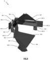
- Each of the locking elements 302-2 can have a suitable housing or shoe acting as a striker to receive one end of a cylinder positioned on the boat 2. effect, as is visible on the Figure 6 , the locking element 302-2 is positioned substantially against the hull of the boat 2 once the bow of the latter comes into contact with the reception structure of the securing system 3.
- a hydraulic cylinder can be positioned at the level of the contact surface between the hull of the boat 2 and the locking element 302-2 in order to hold the boat 2 and minimize shocks between the boat 2 and the launch and recovery platform 1.
- the housing or shoe adapted to receive one end of a jack positioned on the boat 2 could advantageously be removable and replaceable.
- boat 2 may have two hydraulic cylinders retracted on either side of the bow.
- the two cylinders are preferably positioned just below the guide rails of the boat 2 so that when the bow of the boat 2 comes into contact with the reception structure of the securing system 3, each hydraulic cylinder is positioned in view of a locking element 302-2 acting as a striker.
- the security system 3 can include a plurality of damping elements.
- the main function of the damping elements is to absorb the shocks of the boat 2 on the securing system 3 in order to avoid any deformation of the reception structure and in particular of the lower 304 and upper 305 profiles.
- the elements damping can be made of a material such as that described in connection with the lateral centering elements 302-1.
- the securing system 3 may comprise a damping element forming a shoe 304-1 fixed to the lower profile 304 and arranged to absorb a shock between the boat 2 and the floating floor 30.
- the lower profile 304 may comprise two support arms 303 extending radially from the reception structure towards the boat 2. The two support arms 303 are arranged to allow the fixing of a damping element forming a lower cover 306 covering the entire profile lower 304.
- the lower cover advantageously has a shape adapted to the nose of the boat 2, formed in part by the bow of the boat 2, which is thus positioned abutting against the lower cover 306 participating in maintaining the boat 2 and protecting it against abrasions.
- the shoe 304-1 is fixed to the floating floor in a removable or immovable manner.
- part of the floating floor could be formed from integral floats making it possible to create a solid junction associated with the shoe.
- the security system 3 can include a damping element forming an upper cover 307.
- the upper cover 307 is fixed on the upper profile 307 covering the entire upper profile 305
- the upper cover 307 advantageously has a shape adapted to the nose of the boat 2, formed in part by the bow of the boat 2, which is thus positioned abutting against the upper cover 307 participating in maintaining the boat 2 and protecting it against damage. abrasions.
- the securing system 3 may include a damping element forming a stopper 302-3 fixed to the guide arms 302 and arranged to absorb a shock between the boat 2 and the frame 10 of the launch and recovery platform 1 .
- such a security system 3 allows the boat 2 to be maintained in a launch and recovery platform 1 according to the invention and prevents any damage to the boat 2, the security system 3 and the launch and recovery platform 1 , in particular by minimizing or even avoiding rolling, lurching, pitching, yaw, yaw and/or heaving movements which could generate such damage.
- damping elements constitute interchangeable wear parts, that is to say that said damping elements are fixed in a removable manner.
- the launch and recovery platform 1 may also include a floating cradle 50, preferably made of polymer or polymer composite positioned at the entrance to the enclosure formed by the profiles of the frame 10, preferably fixed to at least a third profile of the set of profiles.
- a floating cradle 50 allows support of the hull at the level of the engines of the boat 2, thus relieving the forces on the structure of the hull when the launch and recovery platform 1 is afloat.
- the buoyancy of this floating cradle can be adjusted in partially ballast it to adjust the recovery of the efforts and the trim of the boat 2 on the floor 30 afloat.
- the launch and recovery platform 1 may include ballasts 40 positioned opposite said opening to allow the trim of the assembly to be adjusted during lifting.
- the set of profiles forming the frame 10 can comprise at least one longitudinal profile 105 positioned on one side or preferably both sides of the frame.
- the set of profiles forming the frame 10 comprises two parallel longitudinal profiles 105 positioned respectively on the two sides as an extension of the entrance to the enclosure.
- the launch and recovery platform 1 may include guide means 61 and a plurality of fenders 62. These elements will facilitate the positioning of the boat 2 within the frame 10.
- the guide means 61 may take the form of slides guarding in particular the entrance to the frame 10, said slides being fixed to the ends of the longitudinal profiles 105 of the frame 10 facilitating on the one hand the entry of the boat 2 and on the other hand on the other hand its positioning at the level of the security system 3 in the launch and recovery platform 1.
- the guide means 61 can take the form of tubes, tube sections, pads, inflatable air chambers, or even rubber or polymer rollers.
- the guide means 61 can for example correspond to guide rails fixed to each of the longitudinal profiles 105 and positioned at the entrance to the launch and recovery platform 1.
- the fenders 62 can advantageously be fixed on all or part of each of the longitudinal profiles 105 in order to cushion and protect the boat 2 during its entry or exit from the launch and recovery platform 1.
- the set of profiles may comprise at least one longitudinal profile 105 positioned on a face adjacent to the entrance to the enclosure and adjacent to the support floor 11, said longitudinal profile further comprising the guide means 61 and a plurality of fenders 62.
- the guide means 61 and the plurality of fenders 62 are advantageously fixed to the longitudinal profiles 105.
- Launch and recovery platform 1 can be used in the absence of any engine. In fact, it can be designed to be moored to a quay, to be anchored in open water or even to be stored above water.
- Platform 1 may also be equipped with wheels or skids allowing it to be launched into and out of the water on an inclined plane or launching slipway. Its movement can be carried out using a cable and a winch located on the hold or on platform 1.
- the wheel system can also be operated by motors powered by an electric or hydraulic device located on the platform 1.
- the launch and recovery platform 1 may be equipped with one or more motors allowing it to move, preferably autonomously in the waters whether or not it is loaded with a boat.
- the platform 1 may include electric motors capable of dynamic positioning of the platform 1 for example in relation to the boat 2.
- the platform 1 may include a control module configured to allow remote control of the platform and/or autonomous navigation.
- Platform 1 may also be equipped with means of communication for example radio, GSM or satellite and/or location with for example a GNSS system (Geolocation and Navigation by a Satellite System).
- the means of communication may in particular be configured to establish a relay between the boat and a ship or a maritime construction wishing to control or communicate with the boat 2.
- launch and recovery platform 1 may be equipped with energy storage systems, whether in the form of electrical energy, fuel cells or even fossil fuel.
- energy storage systems whether in the form of electrical energy, fuel cells or even fossil fuel.
- Such a platform could be used to at least partially refuel the boats accommodated at the level of the frame 10.
- the energy stored on board (for example, batteries) may be necessary by the platform 1 to power navigation lights or communications equipment if these elements are present.
- the platform 1 can include an enclosure intended to accommodate a boat 2 but it can also include several enclosures or an enclosure intended to accommodate several boats 2.
- the invention relates to the use of a launch and recovery platform 1 according to the invention as an autonomous receptacle of a boat 2.
- such a platform is particularly relevant in the context of a process of launching or recovering a boat at sea and in particular when the sea is rough.
- the invention relates to a method 200 for launching a boat 2.
- a method of launching a boat 2 is illustrated in Figure 10 and it preferably uses a launch and recovery platform 1 according to the invention.
- Such a method may include a step of lifting 240 of the launch and recovery platform 1 supporting the boat 2, and a step of launching into the water 250 of said launch and recovery platform comprising the boat 2.
- the floating method 200 may also include a support step 210, via the floating floor 30, of the boat 2 in the launch and recovery platform 1.
- the floating method 200 may include a step 210 of supporting the boat 2 by a cradle of the launch and recovery platform 1.
- the floating method 200 may include a step 220 of attaching the launch and recovery platform 1 comprising the boat 2.
- Boat 2 can be positioned in platform 1 for off-water launch and recovery. However, advantageously, the boat 2 can be positioned in the platform 1 for launching and recovering afloat.
- the boat 2 can be lifted for example by a crane and launched independently with a set of 4 slings, the same for the launching and recovery platform 1, then the boat 2 enters the launching and recovery platform 1. recovery afloat.
- the boat When the boat 2 has already been positioned at the level of the frame 10, before it is launched, the boat can be supported by the floating floor 30 or by a cradle, said cradle preferably comprising a plurality of skids 108.
- a method of launching a boat 2 according to the invention also includes a step 220 of attaching the launch and recovery platform 1, including or not the boat 2.
- the method according to the invention may include a securing step 230 of the boat 2, before the lifting step 240 of the launch and recovery platform 1, within the frame 10.
- this securing step 230 may in particular include the embedding of the bow of the boat 2 in a reception structure of the frame 10.
- the securing step 230 may include the actuation of articulated arms establishing a connection between the frame 10 and the boat 2. These articulated arms may be positioned on the boat 2 or on the frame 10. Preferably they are positioned on the frame 10 and more particularly within a security system 3. However, the securing step 230 may preferably include the actuation of articulated arms positioned on the boat 2 establishing a connection between the armature 10 and the boat 2. More preferably, the securing step may preferably involve locking the cylinders integrated into the hull of the boat 2 in the locking elements 302-2 acting as a striker.
- the guide arms 302 of the platform 1 according to the invention will be flexible with a spring effect or actuated by pressing on a stop on the bow of the boat causing a leverage effect.
- the guide arms 302 will preferably be configured to fit into a dedicated housing or a dedicated rail and positioned on the frame 10 or the boat 2 and preferably on the boat 2.
- the lifting step 240 of the launch and recovery platform 1, whether or not supporting the boat 2, may be carried out by lifting means such as a crane.
- the method according to the invention comprises a particular step of launching into the water 250.
- the launching step 250 can be carried out by a lifting means such as a crane or by sliding or rolling using means of a winch or wheels with motorized hubs on an inclined plane, a ramp or a slipway.
- this launching step results in the launch and recovery platform 1 moving from an out-of-water position to an afloat position.
- the method according to the invention may include a step of releasing 260 of the boat 2.
- the releasing step 260 may include the actuation of articulated arms such as arms of guidance 302 establishing a connection between the frame 10 and the boat 2.
- the guide arms 302 will preferably be configured to separate from a dedicated housing or a dedicated rail in order to allow the exit of the boat 2 from the platform 1 launch and recovery.
- the floating floor 30 rests on the support floor 11 while in the afloat position the floating floor 30 floats on the surface S1 of the water.
- the boat 2 will preferably rest at least partly on the floating floor 30 and more preferably it will not rest entirely on the floating floor 30.
- the boat 2 rests on a plurality of skids 208 associated with a cradle formed by the frame 10.
- the cradle can be formed by the support floor or by the lower base.
- the invention relates to a method 400 for removing water from a boat 2.
- a process for removing water 400 from a boat 2 is illustrated in Figure 11 and it preferably uses a launch and recovery platform 1 according to the invention.
- the water outlet method 400 may include a step of positioning 410 of the boat 2 on the floating floor 30 of a launch and recovery platform 1, said launch and recovery platform 1 preferably corresponding to the platform 1 according to the present invention.
- the positioning step may include a movement of the boat 2 so as to engage in the entrance to the enclosure of the armature 10. This can be facilitated by the presence of guide means 61.
- the method 400 of leaving the water may also include a step 420 of securing the boat 2 within the frame 10.
- This securing may in particular include the embedding of the bow of the boat 2 in a reception structure of the frame 10.
- the securing step may include the actuation of articulated arms such as guide arms 302 establishing a connection between the frame 10 and the boat 2.
- articulated arms can be positioned on the boat 2 or on the frame 10. Preferably they are positioned on the frame 10 and more particularly within a security system 3.
- the guide arms 302 will preferably be configured to fit into a dedicated housing or a dedicated rail and positioned on the frame 10 or the boat 2 and preferably on the boat 2.
- the securing step may preferably involve locking the cylinders integrated into the shell 2 in the locking elements 302-2 acting as a striker.
- the water outlet method 400 further comprises a step 430 of attaching, to a recovery means, said launching and recovery platform 1 comprising the boat 2.
- the recovery means may be a lifting means such as a crane but also any means capable of extracting a platform from the water such as a motor or winch associated with a ramp, wheels with motorized hubs on an inclined plane, or even a launching slipway .
- the attachment step 430 may be followed by a water exit step 440 from said launch and recovery platform 1 comprising the boat 2.
- This step can be carried out by recovery means. Recovery can be done by lifting but also by sliding or rolling. This step of exiting the water 440 will result in the passage from an afloat position in which the floating floor 30 floats on the surface S1 of the water to an off-float position in which the floating floor 30 rests on the support floor 11.
- this step of exiting the water 440 will result in the passage from a position afloat in which the boat rests at least partly on the floating floor 30, and preferably therefore substantially horizontal or with the front raised, to a position in which the boat rests on the floating floor or on a cradle with the rear of the boat raised, notably facilitating certain maintenance operations.
- the present invention provides a solution allowing the launching and reception of the boat which can be operated simply, without risk for operators, and which is effective in particular in rough seas.
- a solution makes it possible to facilitate subsequent maintenance operations on a boat.
Landscapes
- Engineering & Computer Science (AREA)
- Mechanical Engineering (AREA)
- Ocean & Marine Engineering (AREA)
- Chemical & Material Sciences (AREA)
- Combustion & Propulsion (AREA)
- Bridges Or Land Bridges (AREA)
- Cleaning Or Clearing Of The Surface Of Open Water (AREA)
- Removal Of Floating Material (AREA)
Claims (18)
- Stapellauf- und Bergungsplattform (1) für ein Wasserfahrzeug, umfassend:- ein Gerüst (10), das dazu vorgesehen ist, ein Wasserfahrzeug (2) aufzunehmen, wobei das Gerüst eine Menge von Profilen umfasst, die ein Gehäuse bilden, das einen Eingang und einen Trageboden (11) umfasst,- Schwimmmittel (20), die an dem Gerüst (10) befestigt sind, und- einen schwimmenden Boden (30), der an das Gerüst (10) gekoppelt ist, so dass er vertikal in Bezug auf das Gerüst (10) translationsbeweglich ist,wobei die Stapellauf- und Bergungsplattform (1) dazu eingerichtet ist, von einer Konfiguration, in der der schwimmende Boden (30) auf dem Trageboden (11) aufliegt, wenn die Stapellauf- und Bergungsplattform (1) nicht in einem Schwimmzustand ist, in eine Konfiguration, in der der schwimmende Boden (30) auf der Oberfläche (S1) des Wassers schwimmt, wenn die Stapellauf- und Bergungsplattform (1) im Schwimmzustand ist, überzugehen.
- Stapellauf- und Bergungsplattform (1) nach Anspruch 1, dadurch gekennzeichnet, dass das Gerüst (10) aus Metall oder einer Metalllegierung, wie beispielsweise Stahl, besteht.
- Stapellauf- und Bergungsplattform (1) nach einem der Ansprüche 1 oder 2, dadurch gekennzeichnet, dass sie ferner ein Sicherungssystem (3) umfasst, wobei das Sicherungssystem (3) eine Struktur zur Aufnahme des Wasserfahrzeugs (2), die dazu eingerichtet ist, sich an die Form eines Teils des Bugs des Wasserfahrzeugs (2) anzupassen, und mindestens zwei Führungsarme (302), die dazu eingerichtet sind, das Wasserfahrzeug (2) zu halten, umfasst.
- Stapellauf- und Bergungsplattform (1) nach Anspruch 3, dadurch gekennzeichnet, dass die Aufnahmestruktur eingerichtet ist, so dass sie vertikal in Bezug auf die untere Basis des Gerüsts translationsbeweglich ist, vorzugsweise wobei die Aufnahmestruktur ferner an dem schwimmenden Boden befestigt ist.
- Stapellauf- und Bergungsplattform (1) nach einem der Ansprüche 1 bis 4, dadurch gekennzeichnet, dass der schwimmende Boden (30) ein Mittel (34) zum Anbringen an dem Gerüst (10) umfasst, ausgewählt aus: einer Verbindung vom Gleitschienentyp, einem Ring, der mit Kufen ausgestattet ist, die auf einem Rohr gleiten, einer Schiene oder auch einem Ring, der auf einer vertikalen Struktur des Gerüsts (10) gleiten kann.
- Stapellauf- und Bergungsplattform (1) nach einem der Ansprüche 1 bis 5, dadurch gekennzeichnet, dass der schwimmende Boden (30) mindestens einen Verbindungsring umfasst, der dazu eingerichtet ist, eine Führungsstange (109) zu umgeben, die an dem Gerüst (10) befestigt ist.
- Stapellauf- und Bergungsplattform (1) nach einem der Ansprüche 1 bis 6, wobei der Trageboden (11) ein Hängegerüst bildet, das mehrere Kufen (108) umfasst, die dazu vorgesehen sind, das Wasserfahrzeug zu tragen, wenn die Stapellauf- und Bergungsplattform (1) nicht in der Schwimmzustandsposition ist.
- Stapellauf- und Bergungsplattform (1) nach Anspruch 7, wobei der schwimmende Boden (30) mehrere Öffnungen umfasst, die dazu eingerichtet sind, die Positionierung der mehreren Kufen (108) unter dem Wasserfahrzeug (2) zu ermöglichen, wenn die Stapellauf- und Bergungsplattform (1) nicht in der Schwimmzustandsposition ist.
- Stapellauf- und Bergungsplattform (1) nach einem der Ansprüche 1 bis 6, dadurch gekennzeichnet, dass der schwimmende Boden eingerichtet ist, so dass er das Wasserfahrzeug (2) zumindest zum Teil trägt, wenn die Stapellauf- und Bergungsplattform (1) nicht in der Schwimmzustandsposition ist.
- Stapellauf- und Bergungsplattform (1) nach einem der Ansprüche 1 bis 9, dadurch gekennzeichnet, dass sie eine untere Basis (12) umfasst, die von dem Trageboden (11) getrennt ist, wobei der Trageboden (11) eine Ebene aufweist, die in Bezug auf die untere Basis (12) einen Winkel (β) bildet, der größer als oder gleich 10° ist.
- Stapellauf- und Bergungsplattform (1) nach einem der Ansprüche 1 bis 6, dadurch gekennzeichnet, dass der Trageboden (11) ein Hängegerüst bildet, das mehrere Kufen (108) umfasst, dass der Trageboden (11) eine untere Basis (12) der Stapellauf- und Bergungsplattform (1) bildet und dass die mehreren Kufen 9108) ausgewählte Längen aufweisen, so dass die Längsachse des Wasserfahrzeugs (2), das von dem Hängegerüst getragen wird, einen Winkel (β) in Bezug auf den Trageboden (11) bildet, der größer als oder gleich 10° ist.
- Stapellauf- und Bergungsplattform (1) nach einem der Ansprüche 1 bis 11, dadurch gekennzeichnet, dass sie mindestens einen, vorzugsweise mindestens vier Hebeösen (110) umfasst, die dazu vorgesehen sind, mit einem Hebemittel zusammenzuwirken.
- Stapellauf- und Bergungsplattform (1) nach einem der Ansprüche 1 bis 12, dadurch gekennzeichnet, dass sie ein schwimmendes Hängegerüst (50) umfasst, das am Eingang des Gehäuses, das von den Profilen des Gerüsts (10) gebildet wird, positioniert ist.
- Stapellauf- und Bergungsplattform (1) nach einem der Ansprüche 1 bis 13, dadurch gekennzeichnet, dass sie Führungsmittel (61) und mehrere Fender (62) umfasst.
- Verwendung einer Stapellauf- und Bergungsplattform (1) nach einem der Ansprüche 1 bis 14 als eigenständiges Behältnis für ein Wasserfahrzeug (2).
- Verfahren (200) für einen Stapellauf eines Wasserfahrzeugs (2) mithilfe einer Stapellauf- und Bergungsplattform (1) nach einem der Ansprüche 1 bis 14, wobei das Verfahren umfasst:- einen Schritt eines Ankoppelns (220) der Stapellauf- und Bergungsplattform (1), die das Wasserfahrzeug (2) trägt, und- einen Schritt eines Einwasserns (250) der Stapellauf- und Bergungsplattform (1), die das Wasserfahrzeug (2) umfasst, wobei der Schritt des Einwasserns den Übergang von einer Nicht-Schwimmzustandsposition, in der der schwimmende Boden (30) auf dem Trageboden (11) aufliegt, in eine Schwimmzustandsposition, in der der schwimmende Boden (30) auf der Oberfläche (S1) des Wassers schwimmt und in der das Wasserfahrzeug (2) zumindest zum Teil auf dem schwimmenden Boden (30) aufliegt, bewirkt.
- Verfahren zum Auswassern (400) eines Wasserfahrzeugs (2), wobei das Verfahren umfasst:- einen Schritt eines Positionierens (410) des Wasserfahrzeugs (2) auf dem schwimmenden Boden (30) einer Stapellauf- und Bergungsplattform (1) nach einem der Ansprüche 1 bis 14,- einen Schritt eines Aufnehmens (430) der Stapellauf- und Bergungsplattform (1), die das Wasserfahrzeug (2) umfasst, mit einem Bergungsmittel,- einen Schritt eines Auswasserns (440) der Stapellauf- und Bergungsplattform (1), die das Wasserfahrzeug (2) umfasst, durch das Bergungsmittel, wobei der Schritt des Auswasserns den Übergang von einer Schwimmzustandsposition, in der der schwimmende Boden (30) im Wesentlichen auf der Oberfläche (S1) des Wassers aufliegt, in eine Nicht-Schwimmzustandsposition, in der der schwimmende Boden (30) auf dem Trageboden (11) aufliegt, bewirkt.
- Verfahren zum Auswassern (400) nach Anspruch 17, wobei das Verfahren einen Schritt eines Sicherns (420) des Wasserfahrzeugs (2) umfasst, der das Betätigen von Verriegelungszylindern umfasst, die eine Verbindung zwischen dem Gerüst (10) und dem Wasserfahrzeug (2) herstellen.
Priority Applications (4)
| Application Number | Priority Date | Filing Date | Title |
|---|---|---|---|
| EP20306234.4A EP3984875B1 (de) | 2020-10-16 | 2020-10-16 | Stapellauf- und einbergungsplattform für boot, und entsprechendes stapellauf- und einbergungsverfahren |
| US17/490,337 US11603174B2 (en) | 2020-10-16 | 2021-09-30 | Boat launch and recovery platform and associated method of launching and recovering |
| KR1020210135827A KR20220050793A (ko) | 2020-10-16 | 2021-10-13 | 보트 진수 및 복구 플랫폼 및 진수 및 복구의 관련된 방법 |
| JP2021169048A JP7419322B2 (ja) | 2020-10-16 | 2021-10-14 | ボートの送出及び回収プラットフォーム並びに関連する送出及び回収する方法 |
Applications Claiming Priority (1)
| Application Number | Priority Date | Filing Date | Title |
|---|---|---|---|
| EP20306234.4A EP3984875B1 (de) | 2020-10-16 | 2020-10-16 | Stapellauf- und einbergungsplattform für boot, und entsprechendes stapellauf- und einbergungsverfahren |
Publications (2)
| Publication Number | Publication Date |
|---|---|
| EP3984875A1 EP3984875A1 (de) | 2022-04-20 |
| EP3984875B1 true EP3984875B1 (de) | 2023-10-04 |
Family
ID=73554340
Family Applications (1)
| Application Number | Title | Priority Date | Filing Date |
|---|---|---|---|
| EP20306234.4A Active EP3984875B1 (de) | 2020-10-16 | 2020-10-16 | Stapellauf- und einbergungsplattform für boot, und entsprechendes stapellauf- und einbergungsverfahren |
Country Status (4)
| Country | Link |
|---|---|
| US (1) | US11603174B2 (de) |
| EP (1) | EP3984875B1 (de) |
| JP (1) | JP7419322B2 (de) |
| KR (1) | KR20220050793A (de) |
Families Citing this family (13)
| Publication number | Priority date | Publication date | Assignee | Title |
|---|---|---|---|---|
| JP7779499B2 (ja) | 2020-06-22 | 2025-12-03 | 阪本薬品工業株式会社 | 金属酸化物微粒子の分散剤、及びそれを含有する分散体 |
| JP2023156679A (ja) * | 2022-04-13 | 2023-10-25 | 株式会社三共 | 遊技機 |
| JP2023156678A (ja) * | 2022-04-13 | 2023-10-25 | 株式会社三共 | 遊技機 |
| JP2023156674A (ja) * | 2022-04-13 | 2023-10-25 | 株式会社三共 | 遊技機 |
| JP2023156677A (ja) * | 2022-04-13 | 2023-10-25 | 株式会社三共 | 遊技機 |
| JP2023156676A (ja) * | 2022-04-13 | 2023-10-25 | 株式会社三共 | 遊技機 |
| CN115594306B (zh) * | 2022-10-24 | 2023-04-14 | 江西省水利科学院 | 自驱动式固定化生物反应带复合生物浮床、矩阵系统及测控方法 |
| CN115783183B (zh) * | 2022-11-28 | 2024-12-03 | 中国船舶集团有限公司第七○八研究所 | 水上收放航行器的气囊式艇托架结构及收放系统 |
| CN115848567B (zh) * | 2023-02-10 | 2024-12-13 | 国家深海基地管理中心 | 一种auv便携式收放架 |
| CN116374086B (zh) * | 2023-04-10 | 2024-04-02 | 华中科技大学 | 一种基于曲面柔性导向与双冗余自锁的船艇收放系统 |
| CN116729564B (zh) * | 2023-06-15 | 2025-10-28 | 上海大学 | 一种三角型布局角架式多无人艇布放回收装置 |
| KR102873955B1 (ko) * | 2023-07-10 | 2025-10-21 | 엘아이지넥스원 주식회사 | 크래들 및 이를 포함하는 진회수 시스템 |
| FR3161656A1 (fr) * | 2024-04-25 | 2025-10-31 | Naval Group | Bâtiment naval comprenant une structure flottante de lancement et de récupération d'un engin marin rétractable dans un espace de réception |
Family Cites Families (13)
| Publication number | Priority date | Publication date | Assignee | Title |
|---|---|---|---|---|
| US5485798A (en) * | 1994-03-24 | 1996-01-23 | Samoian; Ronald P. | Boat lift |
| US5860765A (en) * | 1996-02-09 | 1999-01-19 | Cruchelow; Albert | In-water dry dock system with removable centerline insert |
| SE506365C2 (sv) | 1996-04-22 | 1997-12-08 | Jan Groenstrand | Anordning för sjösättning och upptagning av båtar |
| US7021861B2 (en) * | 1998-05-22 | 2006-04-04 | Ipo L.L.C. | Low profile floating lift for watercraft |
| US20080008528A1 (en) * | 2006-03-23 | 2008-01-10 | Sunstream Corporation | Failsafe watercraft lift with convertible leveling system |
| DE102010035952A1 (de) | 2010-08-31 | 2012-03-01 | Blohm + Voss Naval Gmbh | Vorrichtung für Schiffe zur Aufnahme und zum Aussetzen von Wasserfahrzeugen |
| US9604709B2 (en) * | 2012-11-13 | 2017-03-28 | Sean A. Barnes | Boat lift |
| NO3000808T3 (de) * | 2013-09-12 | 2018-02-24 | ||
| US10597127B2 (en) * | 2016-05-20 | 2020-03-24 | Sea Power Boat Lifts, Llc | Boat lift |
| KR102034174B1 (ko) * | 2019-02-27 | 2019-11-08 | 한화시스템 주식회사 | 수중 운동체 진수방법 |
| US10822063B1 (en) * | 2020-01-30 | 2020-11-03 | Sean A. Barnes | Floating platform |
| FR3105775B1 (fr) | 2019-12-26 | 2025-03-14 | Thales Sa | Dispositif de récupération d'un navire à la mer |
| US11390363B2 (en) * | 2020-04-08 | 2022-07-19 | Sean A. Barnes | Boat lift |
-
2020
- 2020-10-16 EP EP20306234.4A patent/EP3984875B1/de active Active
-
2021
- 2021-09-30 US US17/490,337 patent/US11603174B2/en active Active
- 2021-10-13 KR KR1020210135827A patent/KR20220050793A/ko active Pending
- 2021-10-14 JP JP2021169048A patent/JP7419322B2/ja active Active
Also Published As
| Publication number | Publication date |
|---|---|
| US20220119082A1 (en) | 2022-04-21 |
| JP7419322B2 (ja) | 2024-01-22 |
| EP3984875A1 (de) | 2022-04-20 |
| US11603174B2 (en) | 2023-03-14 |
| JP2022066175A (ja) | 2022-04-28 |
| KR20220050793A (ko) | 2022-04-25 |
Similar Documents
| Publication | Publication Date | Title |
|---|---|---|
| EP3984875B1 (de) | Stapellauf- und einbergungsplattform für boot, und entsprechendes stapellauf- und einbergungsverfahren | |
| EP2964515B1 (de) | System und verfahren zur wiederherstellung eines autonomen unterwasserfahrzeugs | |
| EP4124203B1 (de) | System und verfahren zum ausbringen und einholen eines autonomen unterwasserfahrzeugs durch ein von einem schiff geschlepptes einholfahrzeug, unterwasser-erkundungsanordnung | |
| FR3073200B1 (fr) | Structure flottante pour le deploiement et la recuperation d'au moins un engin aquatique autonome par un navire, procede, systeme et navire correspondants | |
| WO2008012473A1 (fr) | Installation et procede de recuperation d'un engin sous-marin ou marin | |
| FR2968268A1 (fr) | Systeme de mise a l'eau et de recuperation d'engins sous-marins, notamment d'engins sous-marins tractes | |
| EP0907553B1 (de) | Vorrichtung zur handhabung von ladung für ein containerschiff | |
| EP1583689B1 (de) | Rettungsschiff für manövrierunfähige schiffe, schiffsrettungsverfahren und verwendung eines rettungsschiffs | |
| EP3209546B1 (de) | System zum aussetzen und bergen von see- und unterseevorrichtungen mit unterstützung durch kippbare schutzkomponenten | |
| FR3062844A1 (fr) | Systeme de mise a l'eau et de recuperation d'un engin propulse depuis le pont d'un navire porteur | |
| WO2021170721A1 (fr) | Navire comportant un système d'adaptation d'un module amovible et module amovible adapté | |
| EP2836421B1 (de) | Modul für die herstellung einer roll-on/roll-off-schwimmbrücke | |
| EP4121345B1 (de) | System zur handhabung von meeres- oder unterwasserdrohnen durch einen schwimmenden ponton mit einem abnehmbaren drohnenschnittstellenmodul, angepasstes schiff | |
| FR2877509A1 (fr) | Systeme interface de transfert d'ernergie electrique entre un navire et une installation portuaire | |
| FR3047229A1 (fr) | Dispositif de deplacement et de mise a terre d'un navire | |
| EP4493456B1 (de) | Geschlepptes unterwasserfahrzeug und system zur bergung solch eines unterwasserfahrzeugs | |
| EP4368490A1 (de) | Schwimmende soft-schnittstelle zur erleichterung der wasseraufbereitung und -rückgewinnung eines schwimmenden oder unterwasserobjekts | |
| EP4452742A1 (de) | System zum manövrieren eines wasserfahrzeugs | |
| FR3161656A1 (fr) | Bâtiment naval comprenant une structure flottante de lancement et de récupération d'un engin marin rétractable dans un espace de réception | |
| WO2014016313A1 (fr) | Unité flottante et ensemble pour la réalisation d'une structure flottante modulaire comportant de telles unitées flottantes | |
| FR2861049A1 (fr) | Procede et dispositif de sauvetage d'un navire accidente et de renflouage d'une epave immergee |
Legal Events
| Date | Code | Title | Description |
|---|---|---|---|
| PUAI | Public reference made under article 153(3) epc to a published international application that has entered the european phase |
Free format text: ORIGINAL CODE: 0009012 |
|
| STAA | Information on the status of an ep patent application or granted ep patent |
Free format text: STATUS: THE APPLICATION HAS BEEN PUBLISHED |
|
| AK | Designated contracting states |
Kind code of ref document: A1 Designated state(s): AL AT BE BG CH CY CZ DE DK EE ES FI FR GB GR HR HU IE IS IT LI LT LU LV MC MK MT NL NO PL PT RO RS SE SI SK SM TR |
|
| RAP1 | Party data changed (applicant data changed or rights of an application transferred) |
Owner name: TOTALENERGIES ONETECH |
|
| STAA | Information on the status of an ep patent application or granted ep patent |
Free format text: STATUS: REQUEST FOR EXAMINATION WAS MADE |
|
| 17P | Request for examination filed |
Effective date: 20221019 |
|
| RBV | Designated contracting states (corrected) |
Designated state(s): AL AT BE BG CH CY CZ DE DK EE ES FI FR GB GR HR HU IE IS IT LI LT LU LV MC MK MT NL NO PL PT RO RS SE SI SK SM TR |
|
| RIC1 | Information provided on ipc code assigned before grant |
Ipc: B63B 27/36 20060101ALI20230412BHEP Ipc: B63B 27/16 20060101AFI20230412BHEP |
|
| GRAP | Despatch of communication of intention to grant a patent |
Free format text: ORIGINAL CODE: EPIDOSNIGR1 |
|
| STAA | Information on the status of an ep patent application or granted ep patent |
Free format text: STATUS: GRANT OF PATENT IS INTENDED |
|
| INTG | Intention to grant announced |
Effective date: 20230519 |
|
| GRAS | Grant fee paid |
Free format text: ORIGINAL CODE: EPIDOSNIGR3 |
|
| GRAA | (expected) grant |
Free format text: ORIGINAL CODE: 0009210 |
|
| STAA | Information on the status of an ep patent application or granted ep patent |
Free format text: STATUS: THE PATENT HAS BEEN GRANTED |
|
| AK | Designated contracting states |
Kind code of ref document: B1 Designated state(s): AL AT BE BG CH CY CZ DE DK EE ES FI FR GB GR HR HU IE IS IT LI LT LU LV MC MK MT NL NO PL PT RO RS SE SI SK SM TR |
|
| P01 | Opt-out of the competence of the unified patent court (upc) registered |
Effective date: 20230825 |
|
| REG | Reference to a national code |
Ref country code: GB Ref legal event code: FG4D Free format text: NOT ENGLISH |
|
| REG | Reference to a national code |
Ref country code: CH Ref legal event code: EP |
|
| REG | Reference to a national code |
Ref country code: DE Ref legal event code: R096 Ref document number: 602020018584 Country of ref document: DE |
|
| REG | Reference to a national code |
Ref country code: IE Ref legal event code: FG4D Free format text: LANGUAGE OF EP DOCUMENT: FRENCH |
|
| REG | Reference to a national code |
Ref country code: NO Ref legal event code: T2 Effective date: 20231004 |
|
| REG | Reference to a national code |
Ref country code: NL Ref legal event code: FP |
|
| REG | Reference to a national code |
Ref country code: LT Ref legal event code: MG9D |
|
| REG | Reference to a national code |
Ref country code: AT Ref legal event code: MK05 Ref document number: 1617515 Country of ref document: AT Kind code of ref document: T Effective date: 20231004 |
|
| PG25 | Lapsed in a contracting state [announced via postgrant information from national office to epo] |
Ref country code: GR Free format text: LAPSE BECAUSE OF FAILURE TO SUBMIT A TRANSLATION OF THE DESCRIPTION OR TO PAY THE FEE WITHIN THE PRESCRIBED TIME-LIMIT Effective date: 20240105 |
|
| PG25 | Lapsed in a contracting state [announced via postgrant information from national office to epo] |
Ref country code: IS Free format text: LAPSE BECAUSE OF FAILURE TO SUBMIT A TRANSLATION OF THE DESCRIPTION OR TO PAY THE FEE WITHIN THE PRESCRIBED TIME-LIMIT Effective date: 20240204 |
|
| PG25 | Lapsed in a contracting state [announced via postgrant information from national office to epo] |
Ref country code: LT Free format text: LAPSE BECAUSE OF FAILURE TO SUBMIT A TRANSLATION OF THE DESCRIPTION OR TO PAY THE FEE WITHIN THE PRESCRIBED TIME-LIMIT Effective date: 20231004 |
|
| PG25 | Lapsed in a contracting state [announced via postgrant information from national office to epo] |
Ref country code: AT Free format text: LAPSE BECAUSE OF FAILURE TO SUBMIT A TRANSLATION OF THE DESCRIPTION OR TO PAY THE FEE WITHIN THE PRESCRIBED TIME-LIMIT Effective date: 20231004 |
|
| PG25 | Lapsed in a contracting state [announced via postgrant information from national office to epo] |
Ref country code: ES Free format text: LAPSE BECAUSE OF FAILURE TO SUBMIT A TRANSLATION OF THE DESCRIPTION OR TO PAY THE FEE WITHIN THE PRESCRIBED TIME-LIMIT Effective date: 20231004 |
|
| PG25 | Lapsed in a contracting state [announced via postgrant information from national office to epo] |
Ref country code: LT Free format text: LAPSE BECAUSE OF FAILURE TO SUBMIT A TRANSLATION OF THE DESCRIPTION OR TO PAY THE FEE WITHIN THE PRESCRIBED TIME-LIMIT Effective date: 20231004 Ref country code: IS Free format text: LAPSE BECAUSE OF FAILURE TO SUBMIT A TRANSLATION OF THE DESCRIPTION OR TO PAY THE FEE WITHIN THE PRESCRIBED TIME-LIMIT Effective date: 20240204 Ref country code: GR Free format text: LAPSE BECAUSE OF FAILURE TO SUBMIT A TRANSLATION OF THE DESCRIPTION OR TO PAY THE FEE WITHIN THE PRESCRIBED TIME-LIMIT Effective date: 20240105 Ref country code: ES Free format text: LAPSE BECAUSE OF FAILURE TO SUBMIT A TRANSLATION OF THE DESCRIPTION OR TO PAY THE FEE WITHIN THE PRESCRIBED TIME-LIMIT Effective date: 20231004 Ref country code: BG Free format text: LAPSE BECAUSE OF FAILURE TO SUBMIT A TRANSLATION OF THE DESCRIPTION OR TO PAY THE FEE WITHIN THE PRESCRIBED TIME-LIMIT Effective date: 20240104 Ref country code: AT Free format text: LAPSE BECAUSE OF FAILURE TO SUBMIT A TRANSLATION OF THE DESCRIPTION OR TO PAY THE FEE WITHIN THE PRESCRIBED TIME-LIMIT Effective date: 20231004 Ref country code: PT Free format text: LAPSE BECAUSE OF FAILURE TO SUBMIT A TRANSLATION OF THE DESCRIPTION OR TO PAY THE FEE WITHIN THE PRESCRIBED TIME-LIMIT Effective date: 20240205 |
|
| REG | Reference to a national code |
Ref country code: DE Ref legal event code: R119 Ref document number: 602020018584 Country of ref document: DE |
|
| PG25 | Lapsed in a contracting state [announced via postgrant information from national office to epo] |
Ref country code: SE Free format text: LAPSE BECAUSE OF FAILURE TO SUBMIT A TRANSLATION OF THE DESCRIPTION OR TO PAY THE FEE WITHIN THE PRESCRIBED TIME-LIMIT Effective date: 20231004 Ref country code: RS Free format text: LAPSE BECAUSE OF FAILURE TO SUBMIT A TRANSLATION OF THE DESCRIPTION OR TO PAY THE FEE WITHIN THE PRESCRIBED TIME-LIMIT Effective date: 20231004 Ref country code: PL Free format text: LAPSE BECAUSE OF FAILURE TO SUBMIT A TRANSLATION OF THE DESCRIPTION OR TO PAY THE FEE WITHIN THE PRESCRIBED TIME-LIMIT Effective date: 20231004 Ref country code: LV Free format text: LAPSE BECAUSE OF FAILURE TO SUBMIT A TRANSLATION OF THE DESCRIPTION OR TO PAY THE FEE WITHIN THE PRESCRIBED TIME-LIMIT Effective date: 20231004 Ref country code: HR Free format text: LAPSE BECAUSE OF FAILURE TO SUBMIT A TRANSLATION OF THE DESCRIPTION OR TO PAY THE FEE WITHIN THE PRESCRIBED TIME-LIMIT Effective date: 20231004 |
|
| REG | Reference to a national code |
Ref country code: CH Ref legal event code: PL |
|
| REG | Reference to a national code |
Ref country code: BE Ref legal event code: MM Effective date: 20231031 |
|
| PG25 | Lapsed in a contracting state [announced via postgrant information from national office to epo] |
Ref country code: LU Free format text: LAPSE BECAUSE OF NON-PAYMENT OF DUE FEES Effective date: 20231016 |
|
| PG25 | Lapsed in a contracting state [announced via postgrant information from national office to epo] |
Ref country code: LU Free format text: LAPSE BECAUSE OF NON-PAYMENT OF DUE FEES Effective date: 20231016 |
|
| PG25 | Lapsed in a contracting state [announced via postgrant information from national office to epo] |
Ref country code: DK Free format text: LAPSE BECAUSE OF FAILURE TO SUBMIT A TRANSLATION OF THE DESCRIPTION OR TO PAY THE FEE WITHIN THE PRESCRIBED TIME-LIMIT Effective date: 20231004 |
|
| PG25 | Lapsed in a contracting state [announced via postgrant information from national office to epo] |
Ref country code: CH Free format text: LAPSE BECAUSE OF NON-PAYMENT OF DUE FEES Effective date: 20231031 |
|
| PG25 | Lapsed in a contracting state [announced via postgrant information from national office to epo] |
Ref country code: CZ Free format text: LAPSE BECAUSE OF FAILURE TO SUBMIT A TRANSLATION OF THE DESCRIPTION OR TO PAY THE FEE WITHIN THE PRESCRIBED TIME-LIMIT Effective date: 20231004 |
|
| PG25 | Lapsed in a contracting state [announced via postgrant information from national office to epo] |
Ref country code: SK Free format text: LAPSE BECAUSE OF FAILURE TO SUBMIT A TRANSLATION OF THE DESCRIPTION OR TO PAY THE FEE WITHIN THE PRESCRIBED TIME-LIMIT Effective date: 20231004 |
|
| PG25 | Lapsed in a contracting state [announced via postgrant information from national office to epo] |
Ref country code: SM Free format text: LAPSE BECAUSE OF FAILURE TO SUBMIT A TRANSLATION OF THE DESCRIPTION OR TO PAY THE FEE WITHIN THE PRESCRIBED TIME-LIMIT Effective date: 20231004 Ref country code: SK Free format text: LAPSE BECAUSE OF FAILURE TO SUBMIT A TRANSLATION OF THE DESCRIPTION OR TO PAY THE FEE WITHIN THE PRESCRIBED TIME-LIMIT Effective date: 20231004 Ref country code: RO Free format text: LAPSE BECAUSE OF FAILURE TO SUBMIT A TRANSLATION OF THE DESCRIPTION OR TO PAY THE FEE WITHIN THE PRESCRIBED TIME-LIMIT Effective date: 20231004 Ref country code: IT Free format text: LAPSE BECAUSE OF FAILURE TO SUBMIT A TRANSLATION OF THE DESCRIPTION OR TO PAY THE FEE WITHIN THE PRESCRIBED TIME-LIMIT Effective date: 20231004 Ref country code: EE Free format text: LAPSE BECAUSE OF FAILURE TO SUBMIT A TRANSLATION OF THE DESCRIPTION OR TO PAY THE FEE WITHIN THE PRESCRIBED TIME-LIMIT Effective date: 20231004 Ref country code: DK Free format text: LAPSE BECAUSE OF FAILURE TO SUBMIT A TRANSLATION OF THE DESCRIPTION OR TO PAY THE FEE WITHIN THE PRESCRIBED TIME-LIMIT Effective date: 20231004 Ref country code: DE Free format text: LAPSE BECAUSE OF NON-PAYMENT OF DUE FEES Effective date: 20240501 Ref country code: CZ Free format text: LAPSE BECAUSE OF FAILURE TO SUBMIT A TRANSLATION OF THE DESCRIPTION OR TO PAY THE FEE WITHIN THE PRESCRIBED TIME-LIMIT Effective date: 20231004 Ref country code: CH Free format text: LAPSE BECAUSE OF NON-PAYMENT OF DUE FEES Effective date: 20231031 |
|
| PLBE | No opposition filed within time limit |
Free format text: ORIGINAL CODE: 0009261 |
|
| STAA | Information on the status of an ep patent application or granted ep patent |
Free format text: STATUS: NO OPPOSITION FILED WITHIN TIME LIMIT |
|
| PG25 | Lapsed in a contracting state [announced via postgrant information from national office to epo] |
Ref country code: MC Free format text: LAPSE BECAUSE OF FAILURE TO SUBMIT A TRANSLATION OF THE DESCRIPTION OR TO PAY THE FEE WITHIN THE PRESCRIBED TIME-LIMIT Effective date: 20231004 |
|
| PG25 | Lapsed in a contracting state [announced via postgrant information from national office to epo] |
Ref country code: MC Free format text: LAPSE BECAUSE OF FAILURE TO SUBMIT A TRANSLATION OF THE DESCRIPTION OR TO PAY THE FEE WITHIN THE PRESCRIBED TIME-LIMIT Effective date: 20231004 Ref country code: BE Free format text: LAPSE BECAUSE OF NON-PAYMENT OF DUE FEES Effective date: 20231031 |
|
| 26N | No opposition filed |
Effective date: 20240705 |
|
| PG25 | Lapsed in a contracting state [announced via postgrant information from national office to epo] |
Ref country code: IE Free format text: LAPSE BECAUSE OF NON-PAYMENT OF DUE FEES Effective date: 20231016 |
|
| PG25 | Lapsed in a contracting state [announced via postgrant information from national office to epo] |
Ref country code: SI Free format text: LAPSE BECAUSE OF FAILURE TO SUBMIT A TRANSLATION OF THE DESCRIPTION OR TO PAY THE FEE WITHIN THE PRESCRIBED TIME-LIMIT Effective date: 20231004 |
|
| PG25 | Lapsed in a contracting state [announced via postgrant information from national office to epo] |
Ref country code: SI Free format text: LAPSE BECAUSE OF FAILURE TO SUBMIT A TRANSLATION OF THE DESCRIPTION OR TO PAY THE FEE WITHIN THE PRESCRIBED TIME-LIMIT Effective date: 20231004 Ref country code: IE Free format text: LAPSE BECAUSE OF NON-PAYMENT OF DUE FEES Effective date: 20231016 |
|
| PG25 | Lapsed in a contracting state [announced via postgrant information from national office to epo] |
Ref country code: FI Free format text: LAPSE BECAUSE OF FAILURE TO SUBMIT A TRANSLATION OF THE DESCRIPTION OR TO PAY THE FEE WITHIN THE PRESCRIBED TIME-LIMIT Effective date: 20231004 |
|
| PG25 | Lapsed in a contracting state [announced via postgrant information from national office to epo] |
Ref country code: CY Free format text: LAPSE BECAUSE OF FAILURE TO SUBMIT A TRANSLATION OF THE DESCRIPTION OR TO PAY THE FEE WITHIN THE PRESCRIBED TIME-LIMIT; INVALID AB INITIO Effective date: 20201016 |
|
| PG25 | Lapsed in a contracting state [announced via postgrant information from national office to epo] |
Ref country code: HU Free format text: LAPSE BECAUSE OF FAILURE TO SUBMIT A TRANSLATION OF THE DESCRIPTION OR TO PAY THE FEE WITHIN THE PRESCRIBED TIME-LIMIT; INVALID AB INITIO Effective date: 20201016 |
|
| PGFP | Annual fee paid to national office [announced via postgrant information from national office to epo] |
Ref country code: NL Payment date: 20251021 Year of fee payment: 6 |
|
| PG25 | Lapsed in a contracting state [announced via postgrant information from national office to epo] |
Ref country code: TR Free format text: LAPSE BECAUSE OF FAILURE TO SUBMIT A TRANSLATION OF THE DESCRIPTION OR TO PAY THE FEE WITHIN THE PRESCRIBED TIME-LIMIT Effective date: 20231004 |
|
| PGFP | Annual fee paid to national office [announced via postgrant information from national office to epo] |
Ref country code: GB Payment date: 20251022 Year of fee payment: 6 |
|
| PGFP | Annual fee paid to national office [announced via postgrant information from national office to epo] |
Ref country code: NO Payment date: 20251024 Year of fee payment: 6 |
|
| PGFP | Annual fee paid to national office [announced via postgrant information from national office to epo] |
Ref country code: FR Payment date: 20251030 Year of fee payment: 6 |