EP2419908B1 - Dispositif de conditionnement pour le transport, le stockage et/ou l'entreposage de produits radioactifs - Google Patents
Dispositif de conditionnement pour le transport, le stockage et/ou l'entreposage de produits radioactifs Download PDFInfo
- Publication number
- EP2419908B1 EP2419908B1 EP10713453.8A EP10713453A EP2419908B1 EP 2419908 B1 EP2419908 B1 EP 2419908B1 EP 10713453 A EP10713453 A EP 10713453A EP 2419908 B1 EP2419908 B1 EP 2419908B1
- Authority
- EP
- European Patent Office
- Prior art keywords
- orifice
- communication
- chamber
- canister
- storage space
- Prior art date
- Legal status (The legal status is an assumption and is not a legal conclusion. Google has not performed a legal analysis and makes no representation as to the accuracy of the status listed.)
- Not-in-force
Links
- 238000003860 storage Methods 0.000 title claims description 75
- 238000004806 packaging method and process Methods 0.000 title claims description 27
- 239000012857 radioactive material Substances 0.000 title description 4
- 238000012432 intermediate storage Methods 0.000 title 1
- 238000004891 communication Methods 0.000 claims description 125
- 239000012530 fluid Substances 0.000 claims description 47
- 230000002285 radioactive effect Effects 0.000 claims description 47
- 239000007789 gas Substances 0.000 claims description 36
- 238000003608 radiolysis reaction Methods 0.000 claims description 16
- 239000002360 explosive Substances 0.000 claims description 12
- 238000000034 method Methods 0.000 claims description 2
- 230000032258 transport Effects 0.000 description 19
- 230000003750 conditioning effect Effects 0.000 description 14
- 239000007788 liquid Substances 0.000 description 8
- 239000001257 hydrogen Substances 0.000 description 5
- 229910052739 hydrogen Inorganic materials 0.000 description 5
- 229910052778 Plutonium Inorganic materials 0.000 description 4
- 230000000694 effects Effects 0.000 description 4
- OYEHPCDNVJXUIW-UHFFFAOYSA-N plutonium atom Chemical compound [Pu] OYEHPCDNVJXUIW-UHFFFAOYSA-N 0.000 description 4
- UFHFLCQGNIYNRP-UHFFFAOYSA-N Hydrogen Chemical compound [H][H] UFHFLCQGNIYNRP-UHFFFAOYSA-N 0.000 description 3
- 238000006073 displacement reaction Methods 0.000 description 3
- 239000011347 resin Substances 0.000 description 3
- 229920005989 resin Polymers 0.000 description 3
- XLYOFNOQVPJJNP-UHFFFAOYSA-N water Substances O XLYOFNOQVPJJNP-UHFFFAOYSA-N 0.000 description 3
- 229910052770 Uranium Inorganic materials 0.000 description 2
- 150000002431 hydrogen Chemical class 0.000 description 2
- 230000000670 limiting effect Effects 0.000 description 2
- 230000007246 mechanism Effects 0.000 description 2
- 239000000203 mixture Substances 0.000 description 2
- 239000003758 nuclear fuel Substances 0.000 description 2
- 210000000056 organ Anatomy 0.000 description 2
- 239000002245 particle Substances 0.000 description 2
- 239000000843 powder Substances 0.000 description 2
- 230000004044 response Effects 0.000 description 2
- 239000007787 solid Substances 0.000 description 2
- DNYWZCXLKNTFFI-UHFFFAOYSA-N uranium Chemical compound [U][U][U][U][U][U][U][U][U][U][U][U][U][U][U][U][U][U][U][U][U][U][U][U][U][U][U][U][U][U][U][U][U][U][U][U][U][U][U][U][U][U][U][U][U][U][U][U][U][U][U][U][U][U][U][U][U][U][U][U][U][U][U][U][U][U][U][U][U][U][U][U][U][U][U][U][U][U][U][U][U][U][U][U][U][U][U][U][U][U][U][U][U][U][U][U][U][U][U][U][U][U][U][U][U][U][U][U][U][U][U][U][U][U] DNYWZCXLKNTFFI-UHFFFAOYSA-N 0.000 description 2
- 125000000391 vinyl group Chemical group [H]C([*])=C([H])[H] 0.000 description 2
- 229920002554 vinyl polymer Polymers 0.000 description 2
- 239000002699 waste material Substances 0.000 description 2
- 241001411320 Eriogonum inflatum Species 0.000 description 1
- 241001080024 Telles Species 0.000 description 1
- PSPBAKLTRUOTFX-UHFFFAOYSA-N [O-2].[Pu+4].[U+6].[O-2].[O-2].[O-2].[O-2] Chemical compound [O-2].[Pu+4].[U+6].[O-2].[O-2].[O-2].[O-2] PSPBAKLTRUOTFX-UHFFFAOYSA-N 0.000 description 1
- 230000009471 action Effects 0.000 description 1
- LBDSXVIYZYSRII-IGMARMGPSA-N alpha-particle Chemical compound [4He+2] LBDSXVIYZYSRII-IGMARMGPSA-N 0.000 description 1
- SHZGCJCMOBCMKK-KGJVWPDLSA-N beta-L-fucose Chemical compound C[C@@H]1O[C@H](O)[C@@H](O)[C@H](O)[C@@H]1O SHZGCJCMOBCMKK-KGJVWPDLSA-N 0.000 description 1
- 230000000295 complement effect Effects 0.000 description 1
- 150000001875 compounds Chemical class 0.000 description 1
- 239000000470 constituent Substances 0.000 description 1
- 229940082150 encore Drugs 0.000 description 1
- 238000004880 explosion Methods 0.000 description 1
- 230000008014 freezing Effects 0.000 description 1
- 238000007710 freezing Methods 0.000 description 1
- 230000005484 gravity Effects 0.000 description 1
- 238000009434 installation Methods 0.000 description 1
- 238000004519 manufacturing process Methods 0.000 description 1
- 239000000463 material Substances 0.000 description 1
- 229910052751 metal Inorganic materials 0.000 description 1
- 239000002184 metal Substances 0.000 description 1
- 238000012986 modification Methods 0.000 description 1
- 230000004048 modification Effects 0.000 description 1
- 238000005457 optimization Methods 0.000 description 1
- 150000002894 organic compounds Chemical class 0.000 description 1
- 230000036961 partial effect Effects 0.000 description 1
- WJWSFWHDKPKKES-UHFFFAOYSA-N plutonium uranium Chemical compound [U].[Pu] WJWSFWHDKPKKES-UHFFFAOYSA-N 0.000 description 1
- 230000002829 reductive effect Effects 0.000 description 1
- 230000000284 resting effect Effects 0.000 description 1
- 230000000717 retained effect Effects 0.000 description 1
- 238000007789 sealing Methods 0.000 description 1
- 230000035939 shock Effects 0.000 description 1
- 239000000126 substance Substances 0.000 description 1
Images


Classifications
-
- G—PHYSICS
- G21—NUCLEAR PHYSICS; NUCLEAR ENGINEERING
- G21F—PROTECTION AGAINST X-RADIATION, GAMMA RADIATION, CORPUSCULAR RADIATION OR PARTICLE BOMBARDMENT; TREATING RADIOACTIVELY CONTAMINATED MATERIAL; DECONTAMINATION ARRANGEMENTS THEREFOR
- G21F5/00—Transportable or portable shielded containers
- G21F5/002—Containers for fluid radioactive wastes
Definitions
- the present invention relates generally to the field of transport and / or storage of a radioactive medium generating by radiolysis flammable and / or explosive gases, such as hydrogen.
- such a radioactive medium is usually placed in an interior storage space defined by a bottle.
- a radioactive medium When several bottles are filled and closed by plugs, they are then arranged on a bottle holder and inserted into a cavity defined by a package.
- the set obtained, called transport package and / or storage of a radioactive medium may for example include ten bottles distributed on the bottle carrier.
- radioactive liquid medium which usually comprises plutonium
- it is likely to generate by radiolysis flammable and / or explosive gases, such as hydrogen.
- the radioactive medium whether it is a liquid in which the radioactive material is in ionic form and / or in the form of solid particles dispersed in the liquid, constitutes an ⁇ -particle emitter which has in particular the particularity of dissociating the hydrogenated molecules, to release flammable gaseous compounds.
- the radiolysed molecules may be part of the medium, and / or the constituent material of the canister.
- the flammable gases produced by radiolysis constitute, in the presence of other gases such as air, an explosive mixture.
- the flammability threshold varies according to the nature of the gas flammable and according to the conditions of temperature and pressure. In the particular case of hydrogen, the flammability threshold in the air is around 4%. This means that when the hydrogen concentration in the air exceeds this threshold, a source of heat or a spark can be enough to ignite the mixture or to produce a violent explosion in the internal storage space, the latter being indeed only partially filled by the radioactive medium, and supplemented by a gaseous sky.
- Another solution could be to keep the same volume of radioactive medium in the bottle, but by enlarging the internal storage space so as to increase the volume of the gas. Nevertheless, this leads to the manufacture of very large bottles, which makes their exploitation difficult, especially during the loading phases of the radioactive medium in the canister, which is generally carried out in a glove box.
- the invention therefore aims to at least partially overcome the disadvantages mentioned above, relating to the achievements of the prior art.
- the invention firstly relates to a packaging device for transporting and / or storing a radioactive medium generating by radiolysis of flammable and / or explosive gases, said device comprising at least one bottle for contain the radioactive medium, said bottle defining an internal storage space accessible through a filling opening of the medium, on which are mounted plug means.
- said device also comprises an enclosure structure, as well as communication means for establishing a first fluid communication between said internal storage space and said enclosure.
- the flammable and / or explosive gases produced by radiolysis during the storage and / or transport of the radioactive medium can spread not only in the unfilled part of the interior storage space of the canister, called gaseous sky, but also in the volume of the enclosure through the presence of said first fluid communication. Since the gases generated by radiolysis can be diluted in a larger volume than that of the simple gas sky of the canister, each can can therefore contain a larger amount of radioactive medium, without risking to reach the threshold of flammability of these gas. This increase in the filling rate of the canisters implies a significant economic gain, since for a given amount of medium, it reduces the number of transports to be performed.
- the invention also makes it possible to increase the duration of transport / storage, without risking to reach the flammability threshold of the gases generated by radiolysis, always because these gases can be diluted in a larger volume.
- each bottle can remain small in size, favoring easier operation, particularly with regard to the operation of filling of the medium in the internal storage space, which is usually done in a glove box. It is only after the filling and the installation of the cap means that the internal storage space and the enclosure are put into fluid communication.
- each bottle is preferably designed to be arranged outside the chamber, preferably being removably mounted on the structure, it is possible to provide an embodiment in which each bottle is housed in the enclosure with which its internal storage space communicates. Also, in the case where the canisters are arranged outside the enclosure, they can alternatively be placed at a distance from the enclosure structure without being mounted mechanically thereon.
- the invention applies to the conditioning of radioactive liquid media, but also to the packaging of all other radioactive media capable of generating, by radiolysis, flammable and / or explosive gases.
- the bottle further comprises a first orifice opening into the internal storage space, said enclosure structure comprises a second orifice opening into said enclosure, and said first and second ports constitute the two opposite ends of said first fluid communication.
- This first embodiment corresponds to a case where the bottle is intended to be arranged outside the enclosure, being preferably removably mounted on the structure.
- Said first fluid communication can integrate any element between the first and second orifices, in particular controllable means alternatively for releasing / closing these first and second orifices.
- said communication means preferably comprise a first movable member between an open position in which it establishes said first fluidic communication, and a closed position in which it closes said second orifice, said first movable member being mounted on said enclosure structure.
- This first movable member can indifferently constitute an actuating member for establishing the first fluid communication, or constitute a follower member of this actuating member.
- the actuator can be manually controlled by an operator, or be set in motion automatically, in response to an operator-activated signal.
- the bottle further comprises a third orifice opening into the internal storage space
- said enclosure structure comprises a fourth orifice opening into said enclosure
- said communicating means makes it possible to establish a second fluid communication between said internal storage space and said enclosure, said third and fourth orifices constituting the two opposite ends of said second fluid communication.
- the flammable and / or explosive gases produced by radiolysis during the storage and / or transport of the radioactive medium can spread in the volume of the enclosure by borrowing both said first fluid communication and said second fluid communication.
- a number of fluidic communications greater than two could be provided between the chamber and the interior storage space of the canopy, without departing from the scope of the invention.
- the bottle further comprises a third orifice opening into the internal storage space
- said enclosure structure comprises a fourth orifice opening into said enclosure
- said communicating means make it possible to establish a second fluid communication between said internal storage space and said enclosure
- said third and fourth orifices constituting the two opposite ends of said second fluid communication
- fifth and sixth orifices are formed in the enclosure structure, and communicate with each other through a connecting conduit integral with said communicating means.
- the first movable member can indifferently constitute an actuating member for establishing the first fluid communication, or constitute a follower member of this actuating member.
- this actuating member may be manually controlled by an operator, or may be set in motion automatically, in response to an operator activated signal.
- said bottle preferably comprises a first additional movable member, movable between an open position in which it establishes said first fluidic communication, and a closed position in which it closes said first orifice, one of the first movable member and the first additional movable member being an actuating member and the other a follower member of the member actuating means, so that the movement of the actuating member from its closed position to its open position causes said follower member to also move from its closed position to its open position, and vice versa.
- the first movable member is dedicated to closing / releasing the second orifice opening into the chamber, while the first additional movable member is dedicated to closing / releasing the first orifice opening into the chamber.
- internal storage space of the canopy, with one or the other of these bodies can be an actuating member, preferably manually operable by an operator, and driving the other of these two bodies.
- said actuator also constitutes a mechanical connection member of said bottle on the enclosure structure, this mechanical connection function thus adding to that of establishing / breaking the first fluid communication.
- the actuating member is designed such that its displacement from its closed position to its open position, with said canister resting on this first movable member, ensures a mechanical connection of the canopy, and so that the moving from its open position to its closed position ensures a mechanical disconnection of this bottle. Therefore, a single action on this actuator can generate simultaneously effects on the mechanical connection, as well as effects on fluid communication.
- said actuating member forms a male or female portion of a bayonet mechanical connection.
- the device comprises a plurality of bottles each associated with communication means for a first fluid communication between its interior space and said enclosure.
- the device comprises a plurality of bottles each associated with communication means for a first fluid communication between its interior space and said enclosure.
- several bottles share the same enclosure, implying an optimization of the device in terms of weight and bulk.
- the invention also relates to an assembly comprising said conditioning device being in any of the forms described above.
- each can houses in its internal storage space a given volume of radioactive medium, defining a level forming a horizontal demarcation with a gas sky completing this internal storage space, said communication means associated with said bottle presenting a first orifice opening into said internal storage space, and arranged so that it is always in communication with the gas, regardless of the orientation in the space of said bottle incorporating said given volume of medium.
- the invention applies more particularly to radioactive liquid media, and, more generally, to any medium whose consistency makes it possible to define a level forming the horizontal demarcation with the gaseous sky.
- this first orifice is made at least partly in a duct projecting inside said internal storage space.
- it opens preferentially near a barycentre of said inner storage space.
- the invention also relates to a transport package and / or storage of a radioactive medium, comprising a package forming a cavity in which is housed an assembly as described above.
- the invention also relates to a transport container and / or storage of a radioactive medium, comprising a package forming a cavity in which is housed a packaging device as described above.
- This container differs from the package mentioned above in that the packaging device is empty, that is to say that it does not contain the radioactive medium.
- This radioactive medium is preferably a liquid in which the radioactive material is in ionic form and / or in the form of solid particles dispersed in the liquid.
- the package 1 comprises a device 2 for conditioning the transport and / or storage of the radioactive medium, this device being also an object of the present invention.
- the conditioning device 2 is housed in a barrel 4 closed by a cover 4a.
- the barrel 4 is then itself housed in the cavity 5 of a package 6, closed by a lid 6a, in order to form the package 1.
- the conditioning device 2 has the particularity of comprising a plurality of bottles 8, as well as a structure 10 forming an enclosure 12.
- Each bottle 8 defines an internal storage space in which the radioactive medium is placed, this space being closed by means 14, by which the can is mechanically connected to the structure 10, removably.
- the structure 10 adopts a generally cylindrical shape of axis 16 and of circular section, which has recesses 18 distributed circumferentially to accommodate the bottles 8.
- each recess 18, similar to an impression, opens radially towards outside and axially downwards, having dimensions slightly greater than those of the canister 8 it receives.
- the bottles 8, arranged parallel to and about the axis 16, can be inserted into their respective recesses by axial displacement and / or radial.
- the opening 20 has a substantially identical diameter to the average diameter of the canister, which also takes a generally cylindrical shape of circular section.
- the bottle can nevertheless take any other form, such as that of a case or box, preferably metal.
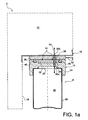
- the cap means 14 comprise a first closure piece 24, for example screwed onto the upper end of the lateral body 26 of the canopy, through which is made a first through hole 30a which opens into the internal storage space 22 This is this piece 24 which covers the opening 20 defined by the lateral body 26.
- the means 14 further comprises a second closure piece 32, for example rotatably mounted on the first closure piece 24, and whose essential function lies in the closing / releasing the first through hole 30a. To do this, the piece 32 also has a through passage 34 may be aligned or eccentric of the first port 30a, depending on the relative angular position between the two closure pieces 24, 32.
- the structure 10 in the form of a wall delimiting the chamber 12, integrates a second through hole 30b, which opens into the chamber 12.
- This second orifice 30b is formed in the part of the structure 10 which defines the end upper imprint 18, facing the means 14 forming the bottle stopper.
- a first movable member 36 is mounted externally on the structure 10, in line with the second orifice 30b, so as to be able to ensure the closure / release of this orifice 30b.
- the movable member 36 also comprises a through passage 38 capable of being aligned or eccentric of the second orifice 30b, as a function of the relative angular position between the movable member 36 and the structure 10.
- the bottle 8 is not only mounted mechanically on the structure 10 in a manner to be described later, but a first fluid communication 40 is also established between the space 22 and the enclosure 12.
- This communication 40 is initiated by the first port 30a, is extended by the passages 34 and 38 being in the continuity of one another, then ends with the second port 30b.
- gas located in the space 22 can pass in a sealed manner towards the chamber 12 by the first channel-forming fluidic communication 40, and vice versa.
- This is of particular importance since the flammable and / or explosive gases produced by radiolysis during the storage and / or transport of the radioactive medium can spread in the internal storage space 22, but also in the volume of the pregnant 12.
- the movable member 36 also performs the function of actuating member, being controllable by an operator, for example by means of a handle or a lever 42. By rotating this member 36, operator can actually move it from its open position shown on the figure 1a wherein it establishes the first fluid communication 40, at a closed position shown on the Figures 1b and 1b ' in which it closes the second orifice 30b, which leads to breaking the communication 40.
- the closing piece 32 When the canopy 8 is mounted on the structure 10, by being pressed against the movable actuating member 36, the latter is coupled in rotation with the second closure piece 32, for example using pins 44 arranged at the interface, carried by one or other of the members 32, 36.
- this member 36 carries with it the closing piece 32 in rotation.
- This last piece 32 then moves simultaneously from its open position shown on the figure 1a wherein it establishes the first fluid communication 40, at its closed position shown on the figure 1b in which it closes the first orifice 30a, which also leads to breaking the communication 40. Due to the rotational drive of which it is the object, the closing piece 32, forming additional mobile member, is described as follower organ.
- sealing means (not shown), of the seal type, are preferably provided so that the closed position of the additional follower member 32 ensures a tight closure of the internal storage space 22 , and so that the closed position of the movable actuating member 36 ensures a tight closure of the enclosure 12.
- the actuating member 36 is controlled manually in the opposite direction to that of the closure.
- the design of the conditioning device 2 is such that the actuating member 36 also constitutes a mechanical connection member of the canopy 8 on the structure 10.
- the actuating member 36 here forms a male part of a bayonet mechanical connection, for example having two pins 46 of inverted T-shaped section, projecting downwards. as shown on figures 1a , 1b 'and 1c .
- the female part of the bayonet mechanical connection is then constituted by the first closure piece 24 of the cap means 14, with grooves 48 open on the upper surface of this part, and each having an enlarged end 48a visible on the Figures 1b 'and 1c . Outside its widened end 48a, each groove 48 has a shape complementary to that of its associated pin 48, namely of inverted T-shaped section, open upwards.
- the can is introduced into its recess 18 so that its first closure piece 24 is pressed against the movable actuating member 36, with the heads spilled T 46 housed in their respective widened ends 48a grooves 48. Then, during the movement by the operator of the member 36 from its closed position to its open position, corresponding for example to a quarter turn, heads reversed T 46s run in the grooves 48 which retain them through their narrowed openings relative to the respective ends 48a. In the open position of the movable member 36, shown on the figure 1a each inverted head 46 is then in its groove 48 at the opposite end of the enlarged end 48a, implying a mechanical connection of the canopy 8 to the structure 10.
- the body mobile is again moved by the operator to his closed position shown on the figure 1b ' , still performing a quarter turn, which has the effect of bringing the inverted heads of T 46 in their respective enlarged ends 48a.
- the bottle 8 mechanically disconnected from the structure 10 only has to be moved axially downwards to be extracted from the conditioning device 2.
- each recess 18 can accommodate a bottle, possibly covered with a vinyl sleeve, but with one or more of these bottles not filled with radioactive medium. This makes it possible to further increase the volume of the packaging device in which the flammable and / or explosive gases can be diluted, since the bottles communicate with each other through the enclosure.
- the second shutter piece 32 belonging to the plug means 14 which performs the function of an organ operable by the operator with its lever 42, and the first movable member 36 mounted externally on the structure 10 which acts as a follower member of the actuating member 32.
- the operation is similar to that presented above, in particular with the actuating member 32 also constituting a mechanical connection member of the canopy 8 on the structure 10.
- the actuating member 32 also forms here a male part of a connection bayonet mechanism, for example having two pins 46 of T-shaped section projecting upwards as shown in FIG. figure 1d .
- the female part of the bayonet mechanical connection is then constituted by the structure 10, with grooves 48 open downwards, and each having an enlarged end 48a, as described above.
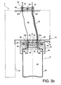
- FIGS. 2a and 2b show a conditioning device 1 in the form of a second preferred embodiment of the present invention, similar to the first mode described above.
- the elements bearing the same reference numerals correspond to identical or similar elements.
- this second mode includes all the features of the first preferred embodiment, to which others have been added in order to be able to establish / break a second fluid communication between the internal storage space. 22 of the canopy and the chamber 12 defined by the structure 10.
- the second fluid communication 49 is initiated by a third orifice 30c opening into the internal storage space 22, is extended by passages 50 and 52 respectively provided on the second closure piece 32 and the first movable member 36, then ends with a fourth orifice 30d opening into the chamber 12.
- the second fluid communication 49 makes it possible to double the already planned one, and is based on the same design. Moreover, the establishment of the first and second communications 40, 49 is obtained simultaneously by the simple operation of the first movable member 36, as the breaking of these first and second communications 40, 49 is obtained simultaneously, also by actuating the first movable member 36.
- the first fluid communication 40 is modified as follows. It is always initiated by the first orifice 30a of the first closure piece 24 of the cap means, then is extended by the through passages 34 and 38 which succeed one another. Then, it continues with a fifth orifice 30e opening into the chamber, corresponding precisely to the second orifice 30b of the previous embodiments.
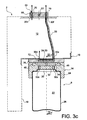
- the first fluid communication 40 is extended by a connecting duct 56 running in the chamber 12, which is thus connected to the fifth orifice 30e at one of its ends, and connected at the other of its ends to a sixth orifice 30f practiced in the structure 10 forming wall of the enclosure. As visible on the figure 3a this sixth orifice 30f is preferably situated on an upper part of the structure 10.
- a second movable member 60 adopting a closed position such as that represented in this figure, makes it possible to put the sixth orifice 30f into communication with a second orifice 30b adjacent practiced in the structure, and opening into the chamber 12.
- the first fluid communication 40 thus ends with the second port 30b.
- the first movable actuating member 36 must occupy its open position described with reference to the previous embodiments, while the second movable member 60 must occupy its closed position in which it ensures communicating the second and sixth orifices 30b, 30f, and further prohibiting the communication of each of these orifices 30b, 30f with the outside of the enclosure.
- the second movable member 60 is mounted externally on the structure 10, to the right of the orifices 30b, 30f, and comprises an U-shaped internal passage 62 sealingly connecting these two orifices 30b, 30f when it occupies its position. closed position.
- the configuration shown on the figure 3a is adopted during the transport / storage of the radioactive medium present in the canisters.
- the flammable and / or explosive gases generated by radiolysis in the inner storage space of the canisters can borrow the two fluidic communications 40, 49 to join the chamber 12 in which they can be diluted.
- the second movable member 60 rotatably mounted on the structure, is also controllable by an operator, for example by means of a handle or a lever 66. By pivoting this member 60, the operator can effectively move from its closed position shown on the figure 3a wherein it establishes the first fluid communication 40, at an open position shown on the figure 3b in which it allows inerting the canopy 8 and the enclosure 12.
- the second movable member 60 aligns the two orifices 30b, 30f with respectively two through passages 68, 70 formed therein, independent of the inner passage 62 in U become inactive, and thus allowing to put in communication each of the second and sixth orifices with the outside of the enclosure.
- the open position of the first movable member 36 is identical to that encountered in the second preferred embodiment.
- this movable member 36 when this movable member 36 is moved by the operator in his closed position as shown on the Figures 3c and 3c ' it does not close the two orifices 30d, 30e it covers, but it ensures a communication of these two holes through a U-shaped inner passage 72 that it defines. It also prohibits the communication of each of these orifices 30d, 30e with the outside of the enclosure, so that the two fluidic communications are broken at this first movable actuating member 36.
- the enclosure 12 is thus sealingly closed at the openings 30d, 30e by the first movable actuating member 36, which makes it possible to perform an inerting of this single enclosure. Indeed, it is possible to inject an inerting gas through the through passage 70 of the second movable member 60, the gas then borrowing the sixth orifice 30f, the connecting duct 56, the fifth orifice 30e, the inner passage in the form of U 72 of the member 36, and the fourth port 30d from which it can enter the enclosure. The inerting gas can then be extracted through the second orifice 30b and the passage 68, and finally be recovered outside the enclosure.
- the canister 8 is mechanically disconnected from the structure 10, and can therefore be removed from the packaging device, as has been shown on the figure 3d .
- the second movable member 60 has been returned to the closed position, so that the enclosure 12 becomes sealed at the openings 30b, 30f, 30d, 30e of the structure 10.
- each bottle is connected by its associated connecting pipe 56 to a sixth orifice 30f which is specific to it.
- a sixth orifice 30f which is specific to it.
- the sixth orifices 30f being for example arranged around this second orifice 30b.
- the structure 10 integrates a fixed wall extension 80, putting in permanent communication the whole sixth ports 30f through an annular groove 82 in which they open.
- the sixth orifices 30f are in communication with the outside of the enclosure by virtue of the alignment of the passage 70 of the member 60 with an outlet orifice 84 made in the extension 80 and opening into the annular groove 82 forming a collector .
- the passage 68 of the member 60 communicates the second single orifice 30b with the outside of the enclosure, by the alignment between the passage 68 and the extension 86 of the orifice 30b formed in the wall extension 80.
- This configuration is that allowing the inerting of the bottles and the enclosure.
- the U-shaped internal passage 62 ensures communication of each of the sixth orifices 30f with the second single orifice 30b, sealingly connecting the extension 86 of the orifice 30b, and the outlet orifice 84 opening into the annular groove 82 associated with the sixth holes 30f.
- the movable member 60 prohibits the communication of each of the second single orifice 30b and the sixth holes 30f with the outside of the enclosure.
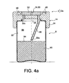
- the first orifice 30a can be realized differently, in a way shown on the Figures 4a and 4b .
- FIG 4a it is shown part of an assembly 2a comprising the conditioning device 2 described above, with each bottle 8 housing in its internal storage space 22 a given volume of radioactive medium 90.
- the assembly 2a is shown in position vertical normal, where the axes of the bottles and the conditioning device 2 are substantially orthogonal to the support surface of the latter 92.
- the given volume of radioactive medium 90 defines a level forming a horizontal demarcation 94 with a gaseous sky 96 completing the internal storage space 22.
- the first orifice 30a is initiated in the first closure piece 24, then extended in a conduit 98 projecting from the same piece 24 inside the internal storage space 22, close to a center of gravity. this last.
- the first orifice 30a is arranged in such a way that it is always in communication with the gaseous sky 96, whatever the orientation in the space of the canopy 8 integrating the given volume of medium 90.
- the first orifice 30a is arranged in such a way that it is always in communication with the gaseous sky 96, whatever the orientation in the space of the canopy 8 integrating the given volume of medium 90.
- the maximum ratio between the given volume of medium and the total volume of the storage space in which it rests may be of the order of 0.5.
- the ratio between the sum of the volumes of the storage spaces of all the bottles of the conditioning device, and the volume of the chamber can be between 0.4 and 0.6.
Landscapes
- Physics & Mathematics (AREA)
- Engineering & Computer Science (AREA)
- General Engineering & Computer Science (AREA)
- High Energy & Nuclear Physics (AREA)
- Packages (AREA)
- Sampling And Sample Adjustment (AREA)
Applications Claiming Priority (2)
| Application Number | Priority Date | Filing Date | Title |
|---|---|---|---|
| FR0952433A FR2944378B1 (fr) | 2009-04-14 | 2009-04-14 | Dispositif de conditionnement pour le stockage et/ou entreposage d'un milieu liquide radioactif |
| PCT/EP2010/054778 WO2010119015A1 (fr) | 2009-04-14 | 2010-04-13 | Dispositif de conditionnement pour le stockage et/ou l'entreposage de produits radioactifs |
Publications (2)
| Publication Number | Publication Date |
|---|---|
| EP2419908A1 EP2419908A1 (fr) | 2012-02-22 |
| EP2419908B1 true EP2419908B1 (fr) | 2013-06-05 |
Family
ID=41337068
Family Applications (1)
| Application Number | Title | Priority Date | Filing Date |
|---|---|---|---|
| EP10713453.8A Not-in-force EP2419908B1 (fr) | 2009-04-14 | 2010-04-13 | Dispositif de conditionnement pour le transport, le stockage et/ou l'entreposage de produits radioactifs |
Country Status (6)
| Country | Link |
|---|---|
| US (1) | US8927954B2 (enExample) |
| EP (1) | EP2419908B1 (enExample) |
| JP (1) | JP5687268B2 (enExample) |
| ES (1) | ES2427281T3 (enExample) |
| FR (1) | FR2944378B1 (enExample) |
| WO (1) | WO2010119015A1 (enExample) |
Families Citing this family (4)
| Publication number | Priority date | Publication date | Assignee | Title |
|---|---|---|---|---|
| US8991436B2 (en) * | 2011-09-26 | 2015-03-31 | Evan Tyler Birch | System and method for covering an opening of a fluid conduit connector |
| GB201404769D0 (en) * | 2014-03-17 | 2014-04-30 | Btg Internat Canada Inc | Controlled orientation containers |
| JP6746922B2 (ja) * | 2016-01-20 | 2020-08-26 | 株式会社Ihi | 放射性廃棄物の貯蔵方法及び装置 |
| CN113066596A (zh) * | 2021-03-23 | 2021-07-02 | 中国原子能科学研究院 | 放射性样品存储装置 |
Family Cites Families (31)
| Publication number | Priority date | Publication date | Assignee | Title |
|---|---|---|---|---|
| US3701900A (en) * | 1969-06-11 | 1972-10-31 | Canrad Precision Ind Inc | Device for illuminating flat carriers with markings |
| FR2113805B1 (enExample) * | 1970-11-17 | 1976-03-19 | Transnucleaire | |
| US3957033A (en) * | 1973-08-15 | 1976-05-18 | General Electric Company | Ventilation study system |
| US3926176A (en) * | 1973-08-15 | 1975-12-16 | Gen Electric | Radioactive gas-containing polymeric capsule |
| US4120414A (en) * | 1977-09-02 | 1978-10-17 | Sterling Drug Inc. | Self-venting cap |
| DE2906629C2 (de) * | 1979-02-21 | 1986-01-23 | Nukem Gmbh, 6450 Hanau | Vorrichtung zur Lagerung Wärme abgebender radioaktiver Materialien |
| DE3014289A1 (de) * | 1980-04-15 | 1981-10-22 | Hoechst Ag, 6000 Frankfurt | Verfahren zum abfuehren der zerfallswaerme radioaktiver substanzen |
| DE3222764A1 (de) * | 1982-06-18 | 1983-12-22 | GNS Gesellschaft für Nuklear-Service mbH, 4300 Essen | Abschirmbehaelter fuer die aufnahme von radioaktiven abfaellen |
| DE3343166A1 (de) * | 1983-11-29 | 1985-06-05 | Alkem Gmbh, 6450 Hanau | Behaelter insbesondere fuer radioaktive substanzen |
| JPS60240657A (ja) * | 1984-05-01 | 1985-11-29 | 中谷 俊雄 | 容器方向自在抽出容器の方法とその装置 |
| DE3511320C1 (de) * | 1985-03-28 | 1986-10-09 | Max-Planck-Gesellschaft zur Förderung der Wissenschaften e.V., 3400 Göttingen | Vorrichtung zur Reinigung der Gasatmosphaeren mehrerer Arbeitsraeume |
| US4747512A (en) * | 1987-06-19 | 1988-05-31 | Lo Kin K | Transportation packaging for liquids |
| JPS646896A (en) * | 1987-06-30 | 1989-01-11 | Toshiba Corp | Method for storing radioactive gas |
| JPH03231200A (ja) * | 1990-02-06 | 1991-10-15 | Toshiba Corp | 放射性廃棄物貯蔵用ドラム缶 |
| US5102615A (en) * | 1990-02-22 | 1992-04-07 | Lou Grande | Metal-clad container for radioactive material storage |
| FR2685244B1 (fr) * | 1991-12-24 | 1994-03-11 | Matieres Nucleaires Cie Gle | Ensemble porte-gant pour une enceinte de confinement. |
| US5273088A (en) * | 1992-05-18 | 1993-12-28 | Motorola, Inc. | Vapor reduction system for solvent bottles |
| DE4314708A1 (de) * | 1993-05-04 | 1994-11-10 | Siemens Ag | Brennstab mit vorbestimmtem Sekundärschaden |
| US5491345A (en) * | 1994-10-03 | 1996-02-13 | Associated Universities, Inc. | Sealed vacuum canister and method for pick-up and containment of material |
| US5464988A (en) * | 1994-11-23 | 1995-11-07 | The United States Of America As Represented By The Department Of Energy | Tritium waste package |
| US5767422A (en) * | 1996-10-02 | 1998-06-16 | Nft Incorporated | Methods of and apparatus for testing and venting drums |
| ZA200007228B (en) * | 1998-10-13 | 2002-08-01 | Gen Electric | Application of noble metals to internal surfaces of operating boiling water reactors in the presence of zinc in reactor water. |
| US6550492B2 (en) * | 1999-12-08 | 2003-04-22 | Ultratech International, Inc. | Filter vent fitting |
| US6608319B2 (en) * | 2001-06-08 | 2003-08-19 | Adrian Joseph | Flexible amorphous composition for high level radiation and environmental protection |
| US20040124374A1 (en) * | 2001-06-08 | 2004-07-01 | Adrian Joseph | Amorphous composition for high level radiation and environmental protection |
| FR2842291B1 (fr) * | 2002-07-11 | 2005-03-11 | Cogema | Procede de sechage de dechets metalliques a tendance pyrophorique, destines a etre compactes; etui de compactage et dispositif associes audit procede |
| US20050105675A1 (en) * | 2002-07-31 | 2005-05-19 | Shivakumar Sitaraman | Systems and methods for estimating helium production in shrouds of nuclear reactors |
| JP2006064625A (ja) * | 2004-08-30 | 2006-03-09 | Mitsui Eng & Shipbuild Co Ltd | 放射性廃棄物の処分容器及びその製造方法 |
| KR100899485B1 (ko) * | 2005-06-14 | 2009-05-26 | 뉴 벤트 디자인스, 인크 | 젖병 조립체 |
| US20080017644A1 (en) * | 2006-02-13 | 2008-01-24 | Wickland Terry J | Storage containers |
| FR2925752B1 (fr) * | 2007-12-21 | 2012-03-09 | Tn Int | Dispositif de transport et/ou de stockage de matieres radioactives concu pour permettre la liberation controlee d'oxygene dans une enceinte fermee |
-
2009
- 2009-04-14 FR FR0952433A patent/FR2944378B1/fr not_active Expired - Fee Related
-
2010
- 2010-04-13 JP JP2012505141A patent/JP5687268B2/ja not_active Expired - Fee Related
- 2010-04-13 ES ES10713453T patent/ES2427281T3/es active Active
- 2010-04-13 US US13/263,987 patent/US8927954B2/en not_active Expired - Fee Related
- 2010-04-13 WO PCT/EP2010/054778 patent/WO2010119015A1/fr not_active Ceased
- 2010-04-13 EP EP10713453.8A patent/EP2419908B1/fr not_active Not-in-force
Also Published As
| Publication number | Publication date |
|---|---|
| JP5687268B2 (ja) | 2015-03-18 |
| JP2012523574A (ja) | 2012-10-04 |
| US20120067761A1 (en) | 2012-03-22 |
| WO2010119015A1 (fr) | 2010-10-21 |
| EP2419908A1 (fr) | 2012-02-22 |
| US8927954B2 (en) | 2015-01-06 |
| FR2944378A1 (fr) | 2010-10-15 |
| FR2944378B1 (fr) | 2011-06-10 |
| ES2427281T3 (es) | 2013-10-29 |
Similar Documents
| Publication | Publication Date | Title |
|---|---|---|
| EP0551782B1 (fr) | Valve doseuse utilisable en position inversée | |
| CA2345649C (fr) | Dispositif d'injection a usage unique destine a etre pre-rempli | |
| EP0453555B1 (fr) | Flacon de stockage contenant un composant d'une solution medicamenteuse | |
| EP0448656B1 (fr) | Conteneur allonge ayant deux compartiments separes disposes dans le prolongement l'un de l'autre | |
| EP2165340B1 (fr) | Emballage de stockage longue durée à fond amovible | |
| FR2790948A1 (fr) | Dispositif de transfert bidirectionnel d'un liquide entre un flacon et une capsule | |
| EP2419908B1 (fr) | Dispositif de conditionnement pour le transport, le stockage et/ou l'entreposage de produits radioactifs | |
| CH666870A5 (fr) | Dispositif de conditionnement de substances liquides ou liquides et solides. | |
| WO2020193917A1 (fr) | Capsule adaptee pour obturer l'ouverture d'un recipient et ensemble comprenant un recipient et ladite capsule | |
| EP0123598B1 (fr) | Enceinte mobile pour le remplacement et le transport de pièces contaminées, et étui complémentaire d'une telle enceinte | |
| FR2861655A1 (fr) | Dispositif d'obturation d'une tubulure de remplissage d'un reservoir a liquide, reservoir equipe d'un tel dispositif et vehicule automobile comprenant un tel reservoir | |
| CH680952A5 (enExample) | ||
| EP2100309B1 (fr) | Dispositif de transfert d'etuis de combustible nucleaire entre un emballage de transport et un dispositif d'entreposage | |
| EP3941845A1 (fr) | Capsule adaptee pour recevoir un fluide et ensemble comprenant un recipient et ladite capsule | |
| FR2924099A1 (fr) | Bouchon permettant la diffusion d'un produit fluide | |
| CH655375A5 (fr) | Valve pour le remplissage d'un recipient a gaz. | |
| EP4126692B1 (fr) | Bouchon adapté pour contenir un fluide | |
| FR2988899A1 (fr) | Conteneur de dechets radioactifs et son procede de fermeture definitive | |
| WO2025074052A1 (fr) | Ensemble compose d'un recipient pour stocker un premier fluide et d'une cartouche pour stocker un deuxieme fluide | |
| EP4572825A1 (fr) | Ensemble comportant un inhalateur de poudre sèche et une boite de stockage | |
| WO2012028822A1 (fr) | Boite de rangement pour sondes afm | |
| CA2087096A1 (fr) | Dispositif pour stocker separement deux constituants et les mettre en presence au moment de l'emploi | |
| FR3066478A1 (fr) | Ensemble destine au conditionnement d'un produit fluidique | |
| CA2045501A1 (fr) | Contenant de forme allongee comportant deux compartiments separes, l'un etant le prolongement de l'autre | |
| FR2801877A1 (fr) | Dispositif de securite pour transverser des liquides toxiques et nocifs, notamment lors de l'utilisation d'appareils melangeurs pour le remplissage des accessoires de distribution de l'energie electrique |
Legal Events
| Date | Code | Title | Description |
|---|---|---|---|
| PUAI | Public reference made under article 153(3) epc to a published international application that has entered the european phase |
Free format text: ORIGINAL CODE: 0009012 |
|
| 17P | Request for examination filed |
Effective date: 20111011 |
|
| AK | Designated contracting states |
Kind code of ref document: A1 Designated state(s): AT BE BG CH CY CZ DE DK EE ES FI FR GB GR HR HU IE IS IT LI LT LU LV MC MK MT NL NO PL PT RO SE SI SK SM TR |
|
| DAX | Request for extension of the european patent (deleted) | ||
| GRAP | Despatch of communication of intention to grant a patent |
Free format text: ORIGINAL CODE: EPIDOSNIGR1 |
|
| GRAS | Grant fee paid |
Free format text: ORIGINAL CODE: EPIDOSNIGR3 |
|
| GRAA | (expected) grant |
Free format text: ORIGINAL CODE: 0009210 |
|
| AK | Designated contracting states |
Kind code of ref document: B1 Designated state(s): AT BE BG CH CY CZ DE DK EE ES FI FR GB GR HR HU IE IS IT LI LT LU LV MC MK MT NL NO PL PT RO SE SI SK SM TR |
|
| REG | Reference to a national code |
Ref country code: GB Ref legal event code: FG4D Free format text: NOT ENGLISH |
|
| REG | Reference to a national code |
Ref country code: CH Ref legal event code: EP |
|
| REG | Reference to a national code |
Ref country code: AT Ref legal event code: REF Ref document number: 616077 Country of ref document: AT Kind code of ref document: T Effective date: 20130615 |
|
| REG | Reference to a national code |
Ref country code: IE Ref legal event code: FG4D Free format text: LANGUAGE OF EP DOCUMENT: FRENCH |
|
| REG | Reference to a national code |
Ref country code: DE Ref legal event code: R096 Ref document number: 602010007612 Country of ref document: DE Effective date: 20130801 |
|
| REG | Reference to a national code |
Ref country code: SE Ref legal event code: TRGR |
|
| REG | Reference to a national code |
Ref country code: NL Ref legal event code: T3 |
|
| REG | Reference to a national code |
Ref country code: AT Ref legal event code: MK05 Ref document number: 616077 Country of ref document: AT Kind code of ref document: T Effective date: 20130605 |
|
| REG | Reference to a national code |
Ref country code: NO Ref legal event code: T2 Effective date: 20130605 |
|
| REG | Reference to a national code |
Ref country code: ES Ref legal event code: FG2A Ref document number: 2427281 Country of ref document: ES Kind code of ref document: T3 Effective date: 20131029 |
|
| PG25 | Lapsed in a contracting state [announced via postgrant information from national office to epo] |
Ref country code: FI Free format text: LAPSE BECAUSE OF FAILURE TO SUBMIT A TRANSLATION OF THE DESCRIPTION OR TO PAY THE FEE WITHIN THE PRESCRIBED TIME-LIMIT Effective date: 20130605 Ref country code: SI Free format text: LAPSE BECAUSE OF FAILURE TO SUBMIT A TRANSLATION OF THE DESCRIPTION OR TO PAY THE FEE WITHIN THE PRESCRIBED TIME-LIMIT Effective date: 20130605 Ref country code: GR Free format text: LAPSE BECAUSE OF FAILURE TO SUBMIT A TRANSLATION OF THE DESCRIPTION OR TO PAY THE FEE WITHIN THE PRESCRIBED TIME-LIMIT Effective date: 20130906 Ref country code: AT Free format text: LAPSE BECAUSE OF FAILURE TO SUBMIT A TRANSLATION OF THE DESCRIPTION OR TO PAY THE FEE WITHIN THE PRESCRIBED TIME-LIMIT Effective date: 20130605 Ref country code: LT Free format text: LAPSE BECAUSE OF FAILURE TO SUBMIT A TRANSLATION OF THE DESCRIPTION OR TO PAY THE FEE WITHIN THE PRESCRIBED TIME-LIMIT Effective date: 20130605 |
|
| REG | Reference to a national code |
Ref country code: SK Ref legal event code: T3 Ref document number: E 14627 Country of ref document: SK |
|
| REG | Reference to a national code |
Ref country code: LT Ref legal event code: MG4D |
|
| PG25 | Lapsed in a contracting state [announced via postgrant information from national office to epo] |
Ref country code: BG Free format text: LAPSE BECAUSE OF FAILURE TO SUBMIT A TRANSLATION OF THE DESCRIPTION OR TO PAY THE FEE WITHIN THE PRESCRIBED TIME-LIMIT Effective date: 20130905 Ref country code: HR Free format text: LAPSE BECAUSE OF FAILURE TO SUBMIT A TRANSLATION OF THE DESCRIPTION OR TO PAY THE FEE WITHIN THE PRESCRIBED TIME-LIMIT Effective date: 20130605 |
|
| PG25 | Lapsed in a contracting state [announced via postgrant information from national office to epo] |
Ref country code: LV Free format text: LAPSE BECAUSE OF FAILURE TO SUBMIT A TRANSLATION OF THE DESCRIPTION OR TO PAY THE FEE WITHIN THE PRESCRIBED TIME-LIMIT Effective date: 20130605 |
|
| PG25 | Lapsed in a contracting state [announced via postgrant information from national office to epo] |
Ref country code: PT Free format text: LAPSE BECAUSE OF FAILURE TO SUBMIT A TRANSLATION OF THE DESCRIPTION OR TO PAY THE FEE WITHIN THE PRESCRIBED TIME-LIMIT Effective date: 20131007 Ref country code: EE Free format text: LAPSE BECAUSE OF FAILURE TO SUBMIT A TRANSLATION OF THE DESCRIPTION OR TO PAY THE FEE WITHIN THE PRESCRIBED TIME-LIMIT Effective date: 20130605 Ref country code: IS Free format text: LAPSE BECAUSE OF FAILURE TO SUBMIT A TRANSLATION OF THE DESCRIPTION OR TO PAY THE FEE WITHIN THE PRESCRIBED TIME-LIMIT Effective date: 20131005 |
|
| PG25 | Lapsed in a contracting state [announced via postgrant information from national office to epo] |
Ref country code: RO Free format text: LAPSE BECAUSE OF FAILURE TO SUBMIT A TRANSLATION OF THE DESCRIPTION OR TO PAY THE FEE WITHIN THE PRESCRIBED TIME-LIMIT Effective date: 20130605 Ref country code: PL Free format text: LAPSE BECAUSE OF FAILURE TO SUBMIT A TRANSLATION OF THE DESCRIPTION OR TO PAY THE FEE WITHIN THE PRESCRIBED TIME-LIMIT Effective date: 20130605 |
|
| PLBE | No opposition filed within time limit |
Free format text: ORIGINAL CODE: 0009261 |
|
| STAA | Information on the status of an ep patent application or granted ep patent |
Free format text: STATUS: NO OPPOSITION FILED WITHIN TIME LIMIT |
|
| PG25 | Lapsed in a contracting state [announced via postgrant information from national office to epo] |
Ref country code: DK Free format text: LAPSE BECAUSE OF FAILURE TO SUBMIT A TRANSLATION OF THE DESCRIPTION OR TO PAY THE FEE WITHIN THE PRESCRIBED TIME-LIMIT Effective date: 20130605 |
|
| 26N | No opposition filed |
Effective date: 20140306 |
|
| REG | Reference to a national code |
Ref country code: DE Ref legal event code: R097 Ref document number: 602010007612 Country of ref document: DE Effective date: 20140306 |
|
| PG25 | Lapsed in a contracting state [announced via postgrant information from national office to epo] |
Ref country code: MC Free format text: LAPSE BECAUSE OF FAILURE TO SUBMIT A TRANSLATION OF THE DESCRIPTION OR TO PAY THE FEE WITHIN THE PRESCRIBED TIME-LIMIT Effective date: 20130605 Ref country code: LU Free format text: LAPSE BECAUSE OF FAILURE TO SUBMIT A TRANSLATION OF THE DESCRIPTION OR TO PAY THE FEE WITHIN THE PRESCRIBED TIME-LIMIT Effective date: 20140413 |
|
| REG | Reference to a national code |
Ref country code: IE Ref legal event code: MM4A |
|
| PG25 | Lapsed in a contracting state [announced via postgrant information from national office to epo] |
Ref country code: IE Free format text: LAPSE BECAUSE OF NON-PAYMENT OF DUE FEES Effective date: 20140413 |
|
| PG25 | Lapsed in a contracting state [announced via postgrant information from national office to epo] |
Ref country code: MT Free format text: LAPSE BECAUSE OF FAILURE TO SUBMIT A TRANSLATION OF THE DESCRIPTION OR TO PAY THE FEE WITHIN THE PRESCRIBED TIME-LIMIT Effective date: 20130605 |
|
| REG | Reference to a national code |
Ref country code: FR Ref legal event code: PLFP Year of fee payment: 7 |
|
| PG25 | Lapsed in a contracting state [announced via postgrant information from national office to epo] |
Ref country code: SM Free format text: LAPSE BECAUSE OF FAILURE TO SUBMIT A TRANSLATION OF THE DESCRIPTION OR TO PAY THE FEE WITHIN THE PRESCRIBED TIME-LIMIT Effective date: 20130605 |
|
| PG25 | Lapsed in a contracting state [announced via postgrant information from national office to epo] |
Ref country code: CY Free format text: LAPSE BECAUSE OF FAILURE TO SUBMIT A TRANSLATION OF THE DESCRIPTION OR TO PAY THE FEE WITHIN THE PRESCRIBED TIME-LIMIT Effective date: 20130605 |
|
| PG25 | Lapsed in a contracting state [announced via postgrant information from national office to epo] |
Ref country code: HU Free format text: LAPSE BECAUSE OF FAILURE TO SUBMIT A TRANSLATION OF THE DESCRIPTION OR TO PAY THE FEE WITHIN THE PRESCRIBED TIME-LIMIT; INVALID AB INITIO Effective date: 20100413 Ref country code: TR Free format text: LAPSE BECAUSE OF FAILURE TO SUBMIT A TRANSLATION OF THE DESCRIPTION OR TO PAY THE FEE WITHIN THE PRESCRIBED TIME-LIMIT Effective date: 20130605 |
|
| REG | Reference to a national code |
Ref country code: FR Ref legal event code: PLFP Year of fee payment: 8 |
|
| REG | Reference to a national code |
Ref country code: FR Ref legal event code: PLFP Year of fee payment: 9 |
|
| PG25 | Lapsed in a contracting state [announced via postgrant information from national office to epo] |
Ref country code: MK Free format text: LAPSE BECAUSE OF FAILURE TO SUBMIT A TRANSLATION OF THE DESCRIPTION OR TO PAY THE FEE WITHIN THE PRESCRIBED TIME-LIMIT Effective date: 20130605 |
|
| PGFP | Annual fee paid to national office [announced via postgrant information from national office to epo] |
Ref country code: NO Payment date: 20210329 Year of fee payment: 12 Ref country code: NL Payment date: 20210312 Year of fee payment: 12 Ref country code: CZ Payment date: 20210319 Year of fee payment: 12 |
|
| PGFP | Annual fee paid to national office [announced via postgrant information from national office to epo] |
Ref country code: SK Payment date: 20210318 Year of fee payment: 12 |
|
| PGFP | Annual fee paid to national office [announced via postgrant information from national office to epo] |
Ref country code: FR Payment date: 20210429 Year of fee payment: 12 Ref country code: IT Payment date: 20210412 Year of fee payment: 12 Ref country code: DE Payment date: 20210408 Year of fee payment: 12 |
|
| PGFP | Annual fee paid to national office [announced via postgrant information from national office to epo] |
Ref country code: SE Payment date: 20210414 Year of fee payment: 12 Ref country code: BE Payment date: 20210421 Year of fee payment: 12 Ref country code: GB Payment date: 20210415 Year of fee payment: 12 Ref country code: CH Payment date: 20210426 Year of fee payment: 12 Ref country code: ES Payment date: 20210506 Year of fee payment: 12 |
|
| REG | Reference to a national code |
Ref country code: DE Ref legal event code: R119 Ref document number: 602010007612 Country of ref document: DE |
|
| REG | Reference to a national code |
Ref country code: SK Ref legal event code: MM4A Ref document number: E 14627 Country of ref document: SK Effective date: 20220413 |
|
| REG | Reference to a national code |
Ref country code: NO Ref legal event code: MMEP |
|
| REG | Reference to a national code |
Ref country code: SE Ref legal event code: EUG |
|
| REG | Reference to a national code |
Ref country code: CH Ref legal event code: PL |
|
| REG | Reference to a national code |
Ref country code: NL Ref legal event code: MM Effective date: 20220501 |
|
| GBPC | Gb: european patent ceased through non-payment of renewal fee |
Effective date: 20220413 |
|
| REG | Reference to a national code |
Ref country code: BE Ref legal event code: MM Effective date: 20220430 |
|
| PG25 | Lapsed in a contracting state [announced via postgrant information from national office to epo] |
Ref country code: SK Free format text: LAPSE BECAUSE OF NON-PAYMENT OF DUE FEES Effective date: 20220413 Ref country code: SE Free format text: LAPSE BECAUSE OF NON-PAYMENT OF DUE FEES Effective date: 20220414 Ref country code: NO Free format text: LAPSE BECAUSE OF NON-PAYMENT OF DUE FEES Effective date: 20220430 Ref country code: NL Free format text: LAPSE BECAUSE OF NON-PAYMENT OF DUE FEES Effective date: 20220501 Ref country code: LI Free format text: LAPSE BECAUSE OF NON-PAYMENT OF DUE FEES Effective date: 20220430 Ref country code: GB Free format text: LAPSE BECAUSE OF NON-PAYMENT OF DUE FEES Effective date: 20220413 Ref country code: FR Free format text: LAPSE BECAUSE OF NON-PAYMENT OF DUE FEES Effective date: 20220430 Ref country code: DE Free format text: LAPSE BECAUSE OF NON-PAYMENT OF DUE FEES Effective date: 20221103 Ref country code: CZ Free format text: LAPSE BECAUSE OF NON-PAYMENT OF DUE FEES Effective date: 20220413 Ref country code: CH Free format text: LAPSE BECAUSE OF NON-PAYMENT OF DUE FEES Effective date: 20220430 |
|
| PG25 | Lapsed in a contracting state [announced via postgrant information from national office to epo] |
Ref country code: BE Free format text: LAPSE BECAUSE OF NON-PAYMENT OF DUE FEES Effective date: 20220430 |
|
| PG25 | Lapsed in a contracting state [announced via postgrant information from national office to epo] |
Ref country code: IT Free format text: LAPSE BECAUSE OF NON-PAYMENT OF DUE FEES Effective date: 20220413 |
|
| REG | Reference to a national code |
Ref country code: ES Ref legal event code: FD2A Effective date: 20230626 |
|
| PG25 | Lapsed in a contracting state [announced via postgrant information from national office to epo] |
Ref country code: ES Free format text: LAPSE BECAUSE OF NON-PAYMENT OF DUE FEES Effective date: 20220414 |