EP2419908B1 - Packaging device for transporting and storage and intermediate storage of radioactive materials - Google Patents
Packaging device for transporting and storage and intermediate storage of radioactive materials Download PDFInfo
- Publication number
- EP2419908B1 EP2419908B1 EP10713453.8A EP10713453A EP2419908B1 EP 2419908 B1 EP2419908 B1 EP 2419908B1 EP 10713453 A EP10713453 A EP 10713453A EP 2419908 B1 EP2419908 B1 EP 2419908B1
- Authority
- EP
- European Patent Office
- Prior art keywords
- orifice
- communication
- chamber
- canister
- storage space
- Prior art date
- Legal status (The legal status is an assumption and is not a legal conclusion. Google has not performed a legal analysis and makes no representation as to the accuracy of the status listed.)
- Not-in-force
Links
Images


Classifications
-
- G—PHYSICS
- G21—NUCLEAR PHYSICS; NUCLEAR ENGINEERING
- G21F—PROTECTION AGAINST X-RADIATION, GAMMA RADIATION, CORPUSCULAR RADIATION OR PARTICLE BOMBARDMENT; TREATING RADIOACTIVELY CONTAMINATED MATERIAL; DECONTAMINATION ARRANGEMENTS THEREFOR
- G21F5/00—Transportable or portable shielded containers
- G21F5/002—Containers for fluid radioactive wastes
Definitions
- the present invention relates generally to the field of transport and / or storage of a radioactive medium generating by radiolysis flammable and / or explosive gases, such as hydrogen.
- such a radioactive medium is usually placed in an interior storage space defined by a bottle.
- a radioactive medium When several bottles are filled and closed by plugs, they are then arranged on a bottle holder and inserted into a cavity defined by a package.
- the set obtained, called transport package and / or storage of a radioactive medium may for example include ten bottles distributed on the bottle carrier.
- radioactive liquid medium which usually comprises plutonium
- it is likely to generate by radiolysis flammable and / or explosive gases, such as hydrogen.
- the radioactive medium whether it is a liquid in which the radioactive material is in ionic form and / or in the form of solid particles dispersed in the liquid, constitutes an ⁇ -particle emitter which has in particular the particularity of dissociating the hydrogenated molecules, to release flammable gaseous compounds.
- the radiolysed molecules may be part of the medium, and / or the constituent material of the canister.
- the flammable gases produced by radiolysis constitute, in the presence of other gases such as air, an explosive mixture.
- the flammability threshold varies according to the nature of the gas flammable and according to the conditions of temperature and pressure. In the particular case of hydrogen, the flammability threshold in the air is around 4%. This means that when the hydrogen concentration in the air exceeds this threshold, a source of heat or a spark can be enough to ignite the mixture or to produce a violent explosion in the internal storage space, the latter being indeed only partially filled by the radioactive medium, and supplemented by a gaseous sky.
- Another solution could be to keep the same volume of radioactive medium in the bottle, but by enlarging the internal storage space so as to increase the volume of the gas. Nevertheless, this leads to the manufacture of very large bottles, which makes their exploitation difficult, especially during the loading phases of the radioactive medium in the canister, which is generally carried out in a glove box.
- the invention therefore aims to at least partially overcome the disadvantages mentioned above, relating to the achievements of the prior art.
- the invention firstly relates to a packaging device for transporting and / or storing a radioactive medium generating by radiolysis of flammable and / or explosive gases, said device comprising at least one bottle for contain the radioactive medium, said bottle defining an internal storage space accessible through a filling opening of the medium, on which are mounted plug means.
- said device also comprises an enclosure structure, as well as communication means for establishing a first fluid communication between said internal storage space and said enclosure.
- the flammable and / or explosive gases produced by radiolysis during the storage and / or transport of the radioactive medium can spread not only in the unfilled part of the interior storage space of the canister, called gaseous sky, but also in the volume of the enclosure through the presence of said first fluid communication. Since the gases generated by radiolysis can be diluted in a larger volume than that of the simple gas sky of the canister, each can can therefore contain a larger amount of radioactive medium, without risking to reach the threshold of flammability of these gas. This increase in the filling rate of the canisters implies a significant economic gain, since for a given amount of medium, it reduces the number of transports to be performed.
- the invention also makes it possible to increase the duration of transport / storage, without risking to reach the flammability threshold of the gases generated by radiolysis, always because these gases can be diluted in a larger volume.
- each bottle can remain small in size, favoring easier operation, particularly with regard to the operation of filling of the medium in the internal storage space, which is usually done in a glove box. It is only after the filling and the installation of the cap means that the internal storage space and the enclosure are put into fluid communication.
- each bottle is preferably designed to be arranged outside the chamber, preferably being removably mounted on the structure, it is possible to provide an embodiment in which each bottle is housed in the enclosure with which its internal storage space communicates. Also, in the case where the canisters are arranged outside the enclosure, they can alternatively be placed at a distance from the enclosure structure without being mounted mechanically thereon.
- the invention applies to the conditioning of radioactive liquid media, but also to the packaging of all other radioactive media capable of generating, by radiolysis, flammable and / or explosive gases.
- the bottle further comprises a first orifice opening into the internal storage space, said enclosure structure comprises a second orifice opening into said enclosure, and said first and second ports constitute the two opposite ends of said first fluid communication.
- This first embodiment corresponds to a case where the bottle is intended to be arranged outside the enclosure, being preferably removably mounted on the structure.
- Said first fluid communication can integrate any element between the first and second orifices, in particular controllable means alternatively for releasing / closing these first and second orifices.
- said communication means preferably comprise a first movable member between an open position in which it establishes said first fluidic communication, and a closed position in which it closes said second orifice, said first movable member being mounted on said enclosure structure.
- This first movable member can indifferently constitute an actuating member for establishing the first fluid communication, or constitute a follower member of this actuating member.
- the actuator can be manually controlled by an operator, or be set in motion automatically, in response to an operator-activated signal.
- the bottle further comprises a third orifice opening into the internal storage space
- said enclosure structure comprises a fourth orifice opening into said enclosure
- said communicating means makes it possible to establish a second fluid communication between said internal storage space and said enclosure, said third and fourth orifices constituting the two opposite ends of said second fluid communication.
- the flammable and / or explosive gases produced by radiolysis during the storage and / or transport of the radioactive medium can spread in the volume of the enclosure by borrowing both said first fluid communication and said second fluid communication.
- a number of fluidic communications greater than two could be provided between the chamber and the interior storage space of the canopy, without departing from the scope of the invention.
- the bottle further comprises a third orifice opening into the internal storage space
- said enclosure structure comprises a fourth orifice opening into said enclosure
- said communicating means make it possible to establish a second fluid communication between said internal storage space and said enclosure
- said third and fourth orifices constituting the two opposite ends of said second fluid communication
- fifth and sixth orifices are formed in the enclosure structure, and communicate with each other through a connecting conduit integral with said communicating means.
- the first movable member can indifferently constitute an actuating member for establishing the first fluid communication, or constitute a follower member of this actuating member.
- this actuating member may be manually controlled by an operator, or may be set in motion automatically, in response to an operator activated signal.
- said bottle preferably comprises a first additional movable member, movable between an open position in which it establishes said first fluidic communication, and a closed position in which it closes said first orifice, one of the first movable member and the first additional movable member being an actuating member and the other a follower member of the member actuating means, so that the movement of the actuating member from its closed position to its open position causes said follower member to also move from its closed position to its open position, and vice versa.
- the first movable member is dedicated to closing / releasing the second orifice opening into the chamber, while the first additional movable member is dedicated to closing / releasing the first orifice opening into the chamber.
- internal storage space of the canopy, with one or the other of these bodies can be an actuating member, preferably manually operable by an operator, and driving the other of these two bodies.
- said actuator also constitutes a mechanical connection member of said bottle on the enclosure structure, this mechanical connection function thus adding to that of establishing / breaking the first fluid communication.
- the actuating member is designed such that its displacement from its closed position to its open position, with said canister resting on this first movable member, ensures a mechanical connection of the canopy, and so that the moving from its open position to its closed position ensures a mechanical disconnection of this bottle. Therefore, a single action on this actuator can generate simultaneously effects on the mechanical connection, as well as effects on fluid communication.
- said actuating member forms a male or female portion of a bayonet mechanical connection.
- the device comprises a plurality of bottles each associated with communication means for a first fluid communication between its interior space and said enclosure.
- the device comprises a plurality of bottles each associated with communication means for a first fluid communication between its interior space and said enclosure.
- several bottles share the same enclosure, implying an optimization of the device in terms of weight and bulk.
- the invention also relates to an assembly comprising said conditioning device being in any of the forms described above.
- each can houses in its internal storage space a given volume of radioactive medium, defining a level forming a horizontal demarcation with a gas sky completing this internal storage space, said communication means associated with said bottle presenting a first orifice opening into said internal storage space, and arranged so that it is always in communication with the gas, regardless of the orientation in the space of said bottle incorporating said given volume of medium.
- the invention applies more particularly to radioactive liquid media, and, more generally, to any medium whose consistency makes it possible to define a level forming the horizontal demarcation with the gaseous sky.
- this first orifice is made at least partly in a duct projecting inside said internal storage space.
- it opens preferentially near a barycentre of said inner storage space.
- the invention also relates to a transport package and / or storage of a radioactive medium, comprising a package forming a cavity in which is housed an assembly as described above.
- the invention also relates to a transport container and / or storage of a radioactive medium, comprising a package forming a cavity in which is housed a packaging device as described above.
- This container differs from the package mentioned above in that the packaging device is empty, that is to say that it does not contain the radioactive medium.
- This radioactive medium is preferably a liquid in which the radioactive material is in ionic form and / or in the form of solid particles dispersed in the liquid.
- the package 1 comprises a device 2 for conditioning the transport and / or storage of the radioactive medium, this device being also an object of the present invention.
- the conditioning device 2 is housed in a barrel 4 closed by a cover 4a.
- the barrel 4 is then itself housed in the cavity 5 of a package 6, closed by a lid 6a, in order to form the package 1.
- the conditioning device 2 has the particularity of comprising a plurality of bottles 8, as well as a structure 10 forming an enclosure 12.
- Each bottle 8 defines an internal storage space in which the radioactive medium is placed, this space being closed by means 14, by which the can is mechanically connected to the structure 10, removably.
- the structure 10 adopts a generally cylindrical shape of axis 16 and of circular section, which has recesses 18 distributed circumferentially to accommodate the bottles 8.
- each recess 18, similar to an impression, opens radially towards outside and axially downwards, having dimensions slightly greater than those of the canister 8 it receives.
- the bottles 8, arranged parallel to and about the axis 16, can be inserted into their respective recesses by axial displacement and / or radial.
- the opening 20 has a substantially identical diameter to the average diameter of the canister, which also takes a generally cylindrical shape of circular section.
- the bottle can nevertheless take any other form, such as that of a case or box, preferably metal.
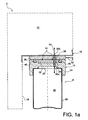
- the cap means 14 comprise a first closure piece 24, for example screwed onto the upper end of the lateral body 26 of the canopy, through which is made a first through hole 30a which opens into the internal storage space 22 This is this piece 24 which covers the opening 20 defined by the lateral body 26.
- the means 14 further comprises a second closure piece 32, for example rotatably mounted on the first closure piece 24, and whose essential function lies in the closing / releasing the first through hole 30a. To do this, the piece 32 also has a through passage 34 may be aligned or eccentric of the first port 30a, depending on the relative angular position between the two closure pieces 24, 32.
- the structure 10 in the form of a wall delimiting the chamber 12, integrates a second through hole 30b, which opens into the chamber 12.
- This second orifice 30b is formed in the part of the structure 10 which defines the end upper imprint 18, facing the means 14 forming the bottle stopper.
- a first movable member 36 is mounted externally on the structure 10, in line with the second orifice 30b, so as to be able to ensure the closure / release of this orifice 30b.
- the movable member 36 also comprises a through passage 38 capable of being aligned or eccentric of the second orifice 30b, as a function of the relative angular position between the movable member 36 and the structure 10.
- the bottle 8 is not only mounted mechanically on the structure 10 in a manner to be described later, but a first fluid communication 40 is also established between the space 22 and the enclosure 12.
- This communication 40 is initiated by the first port 30a, is extended by the passages 34 and 38 being in the continuity of one another, then ends with the second port 30b.
- gas located in the space 22 can pass in a sealed manner towards the chamber 12 by the first channel-forming fluidic communication 40, and vice versa.
- This is of particular importance since the flammable and / or explosive gases produced by radiolysis during the storage and / or transport of the radioactive medium can spread in the internal storage space 22, but also in the volume of the pregnant 12.
- the movable member 36 also performs the function of actuating member, being controllable by an operator, for example by means of a handle or a lever 42. By rotating this member 36, operator can actually move it from its open position shown on the figure 1a wherein it establishes the first fluid communication 40, at a closed position shown on the Figures 1b and 1b ' in which it closes the second orifice 30b, which leads to breaking the communication 40.
- the closing piece 32 When the canopy 8 is mounted on the structure 10, by being pressed against the movable actuating member 36, the latter is coupled in rotation with the second closure piece 32, for example using pins 44 arranged at the interface, carried by one or other of the members 32, 36.
- this member 36 carries with it the closing piece 32 in rotation.
- This last piece 32 then moves simultaneously from its open position shown on the figure 1a wherein it establishes the first fluid communication 40, at its closed position shown on the figure 1b in which it closes the first orifice 30a, which also leads to breaking the communication 40. Due to the rotational drive of which it is the object, the closing piece 32, forming additional mobile member, is described as follower organ.
- sealing means (not shown), of the seal type, are preferably provided so that the closed position of the additional follower member 32 ensures a tight closure of the internal storage space 22 , and so that the closed position of the movable actuating member 36 ensures a tight closure of the enclosure 12.
- the actuating member 36 is controlled manually in the opposite direction to that of the closure.
- the design of the conditioning device 2 is such that the actuating member 36 also constitutes a mechanical connection member of the canopy 8 on the structure 10.
- the actuating member 36 here forms a male part of a bayonet mechanical connection, for example having two pins 46 of inverted T-shaped section, projecting downwards. as shown on figures 1a , 1b 'and 1c .
- the female part of the bayonet mechanical connection is then constituted by the first closure piece 24 of the cap means 14, with grooves 48 open on the upper surface of this part, and each having an enlarged end 48a visible on the Figures 1b 'and 1c . Outside its widened end 48a, each groove 48 has a shape complementary to that of its associated pin 48, namely of inverted T-shaped section, open upwards.
- the can is introduced into its recess 18 so that its first closure piece 24 is pressed against the movable actuating member 36, with the heads spilled T 46 housed in their respective widened ends 48a grooves 48. Then, during the movement by the operator of the member 36 from its closed position to its open position, corresponding for example to a quarter turn, heads reversed T 46s run in the grooves 48 which retain them through their narrowed openings relative to the respective ends 48a. In the open position of the movable member 36, shown on the figure 1a each inverted head 46 is then in its groove 48 at the opposite end of the enlarged end 48a, implying a mechanical connection of the canopy 8 to the structure 10.
- the body mobile is again moved by the operator to his closed position shown on the figure 1b ' , still performing a quarter turn, which has the effect of bringing the inverted heads of T 46 in their respective enlarged ends 48a.
- the bottle 8 mechanically disconnected from the structure 10 only has to be moved axially downwards to be extracted from the conditioning device 2.
- each recess 18 can accommodate a bottle, possibly covered with a vinyl sleeve, but with one or more of these bottles not filled with radioactive medium. This makes it possible to further increase the volume of the packaging device in which the flammable and / or explosive gases can be diluted, since the bottles communicate with each other through the enclosure.
- the second shutter piece 32 belonging to the plug means 14 which performs the function of an organ operable by the operator with its lever 42, and the first movable member 36 mounted externally on the structure 10 which acts as a follower member of the actuating member 32.
- the operation is similar to that presented above, in particular with the actuating member 32 also constituting a mechanical connection member of the canopy 8 on the structure 10.
- the actuating member 32 also forms here a male part of a connection bayonet mechanism, for example having two pins 46 of T-shaped section projecting upwards as shown in FIG. figure 1d .
- the female part of the bayonet mechanical connection is then constituted by the structure 10, with grooves 48 open downwards, and each having an enlarged end 48a, as described above.
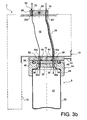
- FIGS. 2a and 2b show a conditioning device 1 in the form of a second preferred embodiment of the present invention, similar to the first mode described above.
- the elements bearing the same reference numerals correspond to identical or similar elements.
- this second mode includes all the features of the first preferred embodiment, to which others have been added in order to be able to establish / break a second fluid communication between the internal storage space. 22 of the canopy and the chamber 12 defined by the structure 10.
- the second fluid communication 49 is initiated by a third orifice 30c opening into the internal storage space 22, is extended by passages 50 and 52 respectively provided on the second closure piece 32 and the first movable member 36, then ends with a fourth orifice 30d opening into the chamber 12.
- the second fluid communication 49 makes it possible to double the already planned one, and is based on the same design. Moreover, the establishment of the first and second communications 40, 49 is obtained simultaneously by the simple operation of the first movable member 36, as the breaking of these first and second communications 40, 49 is obtained simultaneously, also by actuating the first movable member 36.
- the first fluid communication 40 is modified as follows. It is always initiated by the first orifice 30a of the first closure piece 24 of the cap means, then is extended by the through passages 34 and 38 which succeed one another. Then, it continues with a fifth orifice 30e opening into the chamber, corresponding precisely to the second orifice 30b of the previous embodiments.
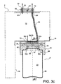
- the first fluid communication 40 is extended by a connecting duct 56 running in the chamber 12, which is thus connected to the fifth orifice 30e at one of its ends, and connected at the other of its ends to a sixth orifice 30f practiced in the structure 10 forming wall of the enclosure. As visible on the figure 3a this sixth orifice 30f is preferably situated on an upper part of the structure 10.
- a second movable member 60 adopting a closed position such as that represented in this figure, makes it possible to put the sixth orifice 30f into communication with a second orifice 30b adjacent practiced in the structure, and opening into the chamber 12.
- the first fluid communication 40 thus ends with the second port 30b.
- the first movable actuating member 36 must occupy its open position described with reference to the previous embodiments, while the second movable member 60 must occupy its closed position in which it ensures communicating the second and sixth orifices 30b, 30f, and further prohibiting the communication of each of these orifices 30b, 30f with the outside of the enclosure.
- the second movable member 60 is mounted externally on the structure 10, to the right of the orifices 30b, 30f, and comprises an U-shaped internal passage 62 sealingly connecting these two orifices 30b, 30f when it occupies its position. closed position.
- the configuration shown on the figure 3a is adopted during the transport / storage of the radioactive medium present in the canisters.
- the flammable and / or explosive gases generated by radiolysis in the inner storage space of the canisters can borrow the two fluidic communications 40, 49 to join the chamber 12 in which they can be diluted.
- the second movable member 60 rotatably mounted on the structure, is also controllable by an operator, for example by means of a handle or a lever 66. By pivoting this member 60, the operator can effectively move from its closed position shown on the figure 3a wherein it establishes the first fluid communication 40, at an open position shown on the figure 3b in which it allows inerting the canopy 8 and the enclosure 12.
- the second movable member 60 aligns the two orifices 30b, 30f with respectively two through passages 68, 70 formed therein, independent of the inner passage 62 in U become inactive, and thus allowing to put in communication each of the second and sixth orifices with the outside of the enclosure.
- the open position of the first movable member 36 is identical to that encountered in the second preferred embodiment.
- this movable member 36 when this movable member 36 is moved by the operator in his closed position as shown on the Figures 3c and 3c ' it does not close the two orifices 30d, 30e it covers, but it ensures a communication of these two holes through a U-shaped inner passage 72 that it defines. It also prohibits the communication of each of these orifices 30d, 30e with the outside of the enclosure, so that the two fluidic communications are broken at this first movable actuating member 36.
- the enclosure 12 is thus sealingly closed at the openings 30d, 30e by the first movable actuating member 36, which makes it possible to perform an inerting of this single enclosure. Indeed, it is possible to inject an inerting gas through the through passage 70 of the second movable member 60, the gas then borrowing the sixth orifice 30f, the connecting duct 56, the fifth orifice 30e, the inner passage in the form of U 72 of the member 36, and the fourth port 30d from which it can enter the enclosure. The inerting gas can then be extracted through the second orifice 30b and the passage 68, and finally be recovered outside the enclosure.
- the canister 8 is mechanically disconnected from the structure 10, and can therefore be removed from the packaging device, as has been shown on the figure 3d .
- the second movable member 60 has been returned to the closed position, so that the enclosure 12 becomes sealed at the openings 30b, 30f, 30d, 30e of the structure 10.
- each bottle is connected by its associated connecting pipe 56 to a sixth orifice 30f which is specific to it.
- a sixth orifice 30f which is specific to it.
- the sixth orifices 30f being for example arranged around this second orifice 30b.
- the structure 10 integrates a fixed wall extension 80, putting in permanent communication the whole sixth ports 30f through an annular groove 82 in which they open.
- the sixth orifices 30f are in communication with the outside of the enclosure by virtue of the alignment of the passage 70 of the member 60 with an outlet orifice 84 made in the extension 80 and opening into the annular groove 82 forming a collector .
- the passage 68 of the member 60 communicates the second single orifice 30b with the outside of the enclosure, by the alignment between the passage 68 and the extension 86 of the orifice 30b formed in the wall extension 80.
- This configuration is that allowing the inerting of the bottles and the enclosure.
- the U-shaped internal passage 62 ensures communication of each of the sixth orifices 30f with the second single orifice 30b, sealingly connecting the extension 86 of the orifice 30b, and the outlet orifice 84 opening into the annular groove 82 associated with the sixth holes 30f.
- the movable member 60 prohibits the communication of each of the second single orifice 30b and the sixth holes 30f with the outside of the enclosure.
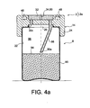
- the first orifice 30a can be realized differently, in a way shown on the Figures 4a and 4b .
- FIG 4a it is shown part of an assembly 2a comprising the conditioning device 2 described above, with each bottle 8 housing in its internal storage space 22 a given volume of radioactive medium 90.
- the assembly 2a is shown in position vertical normal, where the axes of the bottles and the conditioning device 2 are substantially orthogonal to the support surface of the latter 92.
- the given volume of radioactive medium 90 defines a level forming a horizontal demarcation 94 with a gaseous sky 96 completing the internal storage space 22.
- the first orifice 30a is initiated in the first closure piece 24, then extended in a conduit 98 projecting from the same piece 24 inside the internal storage space 22, close to a center of gravity. this last.
- the first orifice 30a is arranged in such a way that it is always in communication with the gaseous sky 96, whatever the orientation in the space of the canopy 8 integrating the given volume of medium 90.
- the first orifice 30a is arranged in such a way that it is always in communication with the gaseous sky 96, whatever the orientation in the space of the canopy 8 integrating the given volume of medium 90.
- the maximum ratio between the given volume of medium and the total volume of the storage space in which it rests may be of the order of 0.5.
- the ratio between the sum of the volumes of the storage spaces of all the bottles of the conditioning device, and the volume of the chamber can be between 0.4 and 0.6.
Description
La présente invention se rapporte de façon générale au domaine du transport et/ou de l'entreposage d'un milieu radioactif générant par radiolyse des gaz inflammables et/ou explosifs, tel que de l'hydrogène.The present invention relates generally to the field of transport and / or storage of a radioactive medium generating by radiolysis flammable and / or explosive gases, such as hydrogen.
Il peut s'agir de milieux radioactifs de différentes sortes, comme par exemple :
- un milieu liquide radioactif ;
- une poudre d'oxyde de plutonium (PuO2) ou d'oxyde mixte uranium-plutonium (U02-PU02), encore appelée poudre MOX, par exemple à teneur en humidité supérieure 0,5 % ;
- des déchets technologiques comportant des composés organiques et éventuellement de l'eau, ces déchets pouvant être contaminés par de l'uranium ou du plutonium conférant à ces matières un caractère radioactif ;
- des crayons de combustible nucléaire pas étanches, irradiés ou frais, pouvant contenir de l'eau ;
- des tronçons de crayons de combustible nucléaire comportant de la résine permettant de figer la matière radioactive.
- a radioactive liquid medium;
- a plutonium oxide powder (PuO2) or mixed uranium-plutonium oxide (U02-PU02), also called MOX powder, for example with a moisture content greater than 0.5%;
- technological waste containing organic compounds and possibly water, which waste may be contaminated by uranium or plutonium conferring on these substances a radioactive character;
- nuclear fuel rods that are not waterproof, irradiated or fresh, that may contain water;
- sections of nuclear fuel rods comprising resin for freezing the radioactive material.
De manière connue, un tel milieu radioactif est habituellement placé dans un espace intérieur de stockage défini par un bouteillon. Lorsque plusieurs bouteillons sont remplis puis fermés par des bouchons, ils sont ensuite agencés sur un porte-bouteillons, puis insérés dans une cavité définie par un emballage. L'ensemble obtenu, appelé colis de transport et/ou d'entreposage d'un milieu radioactif, peut par exemple comprendre dix bouteillons répartis sur le porte-bouteillons.In known manner, such a radioactive medium is usually placed in an interior storage space defined by a bottle. When several bottles are filled and closed by plugs, they are then arranged on a bottle holder and inserted into a cavity defined by a package. The set obtained, called transport package and / or storage of a radioactive medium, may for example include ten bottles distributed on the bottle carrier.
Dans le cas d'un milieu liquide radioactif, qui comprend habituellement du plutonium, celui-ci est susceptible de générer par radiolyse des gaz inflammables et/ou explosifs, tel que de l'hydrogène. Ceci s'explique par le fait que le milieu radioactif, qu'il soit un liquide au sein duquel la matière radioactive se trouve sous forme ionique et/ou sous forme de particules solides dispersées dans le liquide, constitue un émetteur de particules α qui ont notamment la particularité de dissocier les molécules hydrogénées, pour libérer des composés gazeux inflammables. A cet égard, il est noté que les molécules radiolysées peuvent faire partie du milieu, et/ou du matériau constitutif du bouteillon.In the case of a radioactive liquid medium, which usually comprises plutonium, it is likely to generate by radiolysis flammable and / or explosive gases, such as hydrogen. This is explained by the fact that the radioactive medium, whether it is a liquid in which the radioactive material is in ionic form and / or in the form of solid particles dispersed in the liquid, constitutes an α-particle emitter which has in particular the particularity of dissociating the hydrogenated molecules, to release flammable gaseous compounds. In this respect, it is noted that the radiolysed molecules may be part of the medium, and / or the constituent material of the canister.
Quoi qu'il en soit, lorsque leur concentration dépasse une valeur limite dite « seuil d'inflammabilité », les gaz inflammables produits par radiolyse constituent, en présence d'autres gaz tels que l'air, un mélange détonnant. Le seuil d'inflammabilité est variable selon la nature du gaz inflammable et selon les conditions de température et de pression. Dans le cas particulier de l'hydrogène, le seuil d'inflammabilité dans l'air est situé autour de 4%. Cela signifie que lorsque la concentration en hydrogène dans l'air dépasse ce seuil, une source de chaleur ou une étincelle peut suffire à enflammer le mélange ou à produire une déflagration violente dans l'espace intérieur de stockage, ce dernier n'étant en effet que partiellement rempli par le milieu radioactif, et complété par un ciel gazeux.In any case, when their concentration exceeds a limit value known as the "flammability threshold", the flammable gases produced by radiolysis constitute, in the presence of other gases such as air, an explosive mixture. The flammability threshold varies according to the nature of the gas flammable and according to the conditions of temperature and pressure. In the particular case of hydrogen, the flammability threshold in the air is around 4%. This means that when the hydrogen concentration in the air exceeds this threshold, a source of heat or a spark can be enough to ignite the mixture or to produce a violent explosion in the internal storage space, the latter being indeed only partially filled by the radioactive medium, and supplemented by a gaseous sky.
Or diverses études ont montré que la concentration des gaz inflammables, tel que l'hydrogène, produits par radiolyse dans un bouteillon contenant un milieu aqueux plutonifére, peut parfois atteindre des valeurs d'environ 4% au bout de quelques jours. Cependant, il est courant qu'un bouteillon reste fermé pour des durées beaucoup plus longues avant d'être ouvert. Il existe donc un risque réel d'accident, du fait qu'une étincelle occasionnée par des chocs ou des frottements peut se produire en cours de transport dans l'espace intérieur du bouteillon renfermant le ciel gazeux. De plus, ce risque subsiste lors des opérations d'ouverture du bouteillon.However, various studies have shown that the concentration of flammable gases, such as hydrogen, produced by radiolysis in a can containing an aqueous plutoniferous medium, can sometimes reach values of about 4% after a few days. However, it is common for a bottle to remain closed for much longer periods before being opened. There is therefore a real risk of accident, because a spark caused by shocks or friction can occur during transport in the interior space of the canister containing the gas. In addition, this risk remains during the opening operations of the canopy.
Pour faire face à ce problème, le volume du milieu radioactif placé dans le bouteillon peut être réduit. Cela permet d'obtenir un ciel gazeux de volume plus important, dans lequel le seuil d'inflammabilité des gaz inflammables est atteint plus tardivement. Néanmoins, cette solution ne s'avère pas satisfaisante d'un point de vue économique, puisqu'elle nécessite une multiplication des transports.To cope with this problem, the volume of the radioactive medium placed in the canopy can be reduced. This makes it possible to obtain a gaseous sky of greater volume, in which the flammability threshold of the flammable gases is reached later. Nevertheless, this solution is not satisfactory from an economic point of view, since it requires a multiplication of transport.
Une autre solution pourrait consister à conserver le même volume de milieu radioactif dans le bouteillon, mais en agrandissant l'espace intérieur de stockage de façon à augmenter le volume du ciel gazeux. Néanmoins, cela conduit à fabriquer des bouteillons de taille très importante, qui rend difficile leur exploitation, en particulier lors des phases de chargement du milieu radioactif dans le bouteillon, qui s'effectue généralement en boite à gants.Another solution could be to keep the same volume of radioactive medium in the bottle, but by enlarging the internal storage space so as to increase the volume of the gas. Nevertheless, this leads to the manufacture of very large bottles, which makes their exploitation difficult, especially during the loading phases of the radioactive medium in the canister, which is generally carried out in a glove box.
Ce type d'inconvénient survient également avec les autres milieux radioactifs mentionnés ci-dessous, dès lors qu'ils sont susceptibles de générer, par radiolyse, des gaz inflammables et/ou explosifs. Dans tous les cas, c'est toujours l'eau contenue dans le bouteillon qui est radiolysée, à l'exception du cas de la résine, où c'est cette même résine qui est radiolysée.This type of disadvantage also occurs with the other radioactive media mentioned below, since they are capable of generating, by radiolysis, flammable and / or explosive gases. In all cases, it is always the water contained in the bottle which is radiolysed, except for the case of the resin, where it is this same resin which is radiolysed.
L'invention a donc pour but de remédier au moins partiellement aux inconvénients mentionnés ci-dessus, relatifs aux réalisations de l'art antérieur.The invention therefore aims to at least partially overcome the disadvantages mentioned above, relating to the achievements of the prior art.
Pour ce faire, l'invention a tout d'abord pour objet un dispositif de conditionnement pour le transport et/ou entreposage d'un milieu radioactif générant par radiolyse des gaz inflammables et/ou explosifs, ledit dispositif comprenant au moins un bouteillon destiné à contenir le milieu radioactif, ledit bouteillon définissant un espace intérieur de stockage accessible par une ouverture de remplissage du milieu, sur laquelle sont montés des moyens formant bouchon.To do this, the invention firstly relates to a packaging device for transporting and / or storing a radioactive medium generating by radiolysis of flammable and / or explosive gases, said device comprising at least one bottle for contain the radioactive medium, said bottle defining an internal storage space accessible through a filling opening of the medium, on which are mounted plug means.
Selon l'invention, ledit dispositif comporte également une structure formant enceinte, ainsi que des moyens de mise en communication permettant d'établir une première communication fluidique entre ledit espace intérieur de stockage et ladite enceinte.According to the invention, said device also comprises an enclosure structure, as well as communication means for establishing a first fluid communication between said internal storage space and said enclosure.
Ainsi, les gaz inflammables et/ou explosifs produits par radiolyse durant l'entreposage et/ou le transport du milieu radioactif peuvent se répandre non seulement dans la partie non remplie de l'espace intérieur de stockage du bouteillon, dénommée ciel gazeux, mais également dans le volume de l'enceinte grâce à la présence de ladite première communication fluidique. Puisque les gaz générés par radiolyse peuvent se diluer dans un plus grand volume que celui du simple ciel gazeux du bouteillon, chaque bouteillon peut de ce fait contenir une quantité plus importante de milieu radioactif, sans risquer d'atteindre le seuil d'inflammabilité de ces gaz. Cet accroissement du taux de remplissage des bouteillons implique un gain économique important, puisque pour une quantité de milieu donnée, il diminue le nombre de transports à effectuer.Thus, the flammable and / or explosive gases produced by radiolysis during the storage and / or transport of the radioactive medium can spread not only in the unfilled part of the interior storage space of the canister, called gaseous sky, but also in the volume of the enclosure through the presence of said first fluid communication. Since the gases generated by radiolysis can be diluted in a larger volume than that of the simple gas sky of the canister, each can can therefore contain a larger amount of radioactive medium, without risking to reach the threshold of flammability of these gas. This increase in the filling rate of the canisters implies a significant economic gain, since for a given amount of medium, it reduces the number of transports to be performed.
D'autre part, l'invention permet également d'augmenter la durée de transport/d'entreposage, sans risquer d'atteindre le seuil d'inflammabilité des gaz générés par radiolyse, toujours en raison du fait que ces gaz peuvent se diluer dans un plus grand volume.On the other hand, the invention also makes it possible to increase the duration of transport / storage, without risking to reach the flammability threshold of the gases generated by radiolysis, always because these gases can be diluted in a larger volume.
De plus, chaque bouteillon peut rester de dimension restreinte favorisant une exploitation plus aisée, notamment en ce qui concerne l'opération de remplissage du milieu dans l'espace intérieur de stockage, qui se fait habituellement en boite à gants. Ce n'est qu'après le remplissage et la mise en place des moyens formant bouchon que l'espace intérieur de stockage et l'enceinte sont mis en communication fluidique. A cet égard, il est noté que si chaque bouteillon est préférentiellement prévu pour être agencé en dehors de l'enceinte, en étant de préférence monté de manière amovible sur la structure, il est possible de prévoir une réalisation dans laquelle chaque bouteillon est logé dans l'enceinte avec laquelle son espace intérieur de stockage communique. Egalement, dans le cas où les bouteillons sont agencés en dehors de l'enceinte, ils peuvent alternativement être placés à distance de la structure formant enceinte, sans être montés mécaniquement sur celle-ci.In addition, each bottle can remain small in size, favoring easier operation, particularly with regard to the operation of filling of the medium in the internal storage space, which is usually done in a glove box. It is only after the filling and the installation of the cap means that the internal storage space and the enclosure are put into fluid communication. In this regard, it is noted that if each bottle is preferably designed to be arranged outside the chamber, preferably being removably mounted on the structure, it is possible to provide an embodiment in which each bottle is housed in the enclosure with which its internal storage space communicates. Also, in the case where the canisters are arranged outside the enclosure, they can alternatively be placed at a distance from the enclosure structure without being mounted mechanically thereon.
L'invention s'applique au conditionnement de milieux liquides radioactifs, mais également au conditionnement de tous les autres milieux radioactifs susceptibles de générer, par radiolyse, des gaz inflammables et/ou explosifs.The invention applies to the conditioning of radioactive liquid media, but also to the packaging of all other radioactive media capable of generating, by radiolysis, flammable and / or explosive gases.
Selon un premier mode de réalisation préféré de la présente invention,
le bouteillon comporte en outre un premier orifice débouchant dans l'espace intérieur de stockage,
ladite structure formant enceinte comporte un second orifice débouchant dans ladite enceinte,
et lesdits premier et second orifices constituent les deux extrémités opposées de ladite première communication fluidique.According to a first preferred embodiment of the present invention,
the bottle further comprises a first orifice opening into the internal storage space,
said enclosure structure comprises a second orifice opening into said enclosure,
and said first and second ports constitute the two opposite ends of said first fluid communication.
Ce premier mode de réalisation correspond à un cas où le bouteillon est prévu pour être agencé en dehors de l'enceinte, en étant préférentiellement monté de manière amovible sur la structure. Ladite première communication fluidique peut intégrer tout élément entre les premier et second orifices, en particulier des moyens commandables permettant alternativement de libérer / obturer ces premier et second orifices.This first embodiment corresponds to a case where the bottle is intended to be arranged outside the enclosure, being preferably removably mounted on the structure. Said first fluid communication can integrate any element between the first and second orifices, in particular controllable means alternatively for releasing / closing these first and second orifices.
A ce titre, lesdits moyens de mise en communication comprennent de préférence un premier organe mobile entre une position ouverte dans laquelle il établit ladite première communication fluidique, et une position fermée dans laquelle il obture ledit second orifice, ledit premier organe mobile étant monté sur ladite structure formant enceinte.As such, said communication means preferably comprise a first movable member between an open position in which it establishes said first fluidic communication, and a closed position in which it closes said second orifice, said first movable member being mounted on said enclosure structure.
Ce premier organe mobile peut indifféremment constituer un organe d'actionnement visant à établir la première communication fluidique, ou bien constituer un organe suiveur de cet organe d'actionnement. Dans les deux cas, l'organe d'actionnement peut être piloté manuellement par un opérateur, ou bien être mis en mouvement de façon automatisée, en réponse à un signal activé par un opérateur.This first movable member can indifferently constitute an actuating member for establishing the first fluid communication, or constitute a follower member of this actuating member. In both cases, the actuator can be manually controlled by an operator, or be set in motion automatically, in response to an operator-activated signal.
Selon un second mode de réalisation préféré de la présente invention,
le bouteillon comporte en outre un troisième orifice débouchant dans l'espace intérieur de stockage,
ladite structure formant enceinte comporte un quatrième orifice débouchant dans ladite enceinte,
et lesdits moyens de mise en communication permettent d'établir une seconde communication fluidique entre ledit espace intérieur de stockage et ladite enceinte, lesdits troisième et quatrième orifices constituant les deux extrémités opposées de ladite seconde communication fluidique.According to a second preferred embodiment of the present invention,
the bottle further comprises a third orifice opening into the internal storage space,
said enclosure structure comprises a fourth orifice opening into said enclosure,
and said communicating means makes it possible to establish a second fluid communication between said internal storage space and said enclosure, said third and fourth orifices constituting the two opposite ends of said second fluid communication.
Avec ce second mode de réalisation, fortement similaire au premier, les gaz inflammables et/ou explosifs produits par radiolyse durant l'entreposage et/ou le transport du milieu radioactif peuvent se répandre dans le volume de l'enceinte en empruntant à la fois ladite première communication fluidique et ladite seconde communication fluidique. D'ailleurs, un nombre de communications fluidiques supérieur à deux pourrait être prévu entre l'enceinte et l'espace intérieur de stockage du bouteillon, sans sortir du cadre de l'invention.With this second embodiment, which is very similar to the first embodiment, the flammable and / or explosive gases produced by radiolysis during the storage and / or transport of the radioactive medium can spread in the volume of the enclosure by borrowing both said first fluid communication and said second fluid communication. Moreover, a number of fluidic communications greater than two could be provided between the chamber and the interior storage space of the canopy, without departing from the scope of the invention.
Selon un troisième mode de réalisation préféré de la présente invention,
le bouteillon comporte en outre un troisième orifice débouchant dans l'espace intérieur de stockage,
ladite structure formant enceinte comporte un quatrième orifice débouchant dans ladite enceinte,
lesdits moyens de mise en communication permettent d'établir une seconde communication fluidique entre ledit espace intérieur de stockage et ladite enceinte, lesdits troisième et quatrième orifices constituant les deux extrémités opposées de ladite seconde communication fluidique,
et un cinquième et un sixième orifices sont pratiqués dans la structure formant enceinte, et communiquent l'un avec l'autre par un conduit de raccord faisant partie intégrante desdits moyens de mise en communication.According to a third preferred embodiment of the present invention,
the bottle further comprises a third orifice opening into the internal storage space,
said enclosure structure comprises a fourth orifice opening into said enclosure,
said communicating means make it possible to establish a second fluid communication between said internal storage space and said enclosure, said third and fourth orifices constituting the two opposite ends of said second fluid communication,
and fifth and sixth orifices are formed in the enclosure structure, and communicate with each other through a connecting conduit integral with said communicating means.
Ce troisième mode de réalisation préféré est spécialement adapté pour pouvoir réaliser l'inertage des différents composants du dispositif de conditionnement. De préférence, lesdits moyens de mise en communication comprennent un premier organe mobile et un second organe mobile chacun monté sur ladite structure formant enceinte et déplaçable entre une position ouverte et une position fermée, ledit premier organe mobile étant conçu de sorte que :
- en position ouverte, d'une part il met en communication ledit premier orifice avec ledit cinquième orifice, et d'autre part il établit ladite seconde communication fluidique en mettant en communication ledit troisième orifice avec ledit quatrième orifice ;
- en position fermée, d'une part il assure une mise en communication du quatrième orifice avec ledit cinquième orifice, et d'autre part il interdit la communication de chacun des quatrième et cinquième orifices avec l'extérieur de ladite enceinte,
et en ce que ledit second organe mobile étant conçu de sorte que : - en position ouverte, d'une part il met en communication ledit sixième orifice avec l'extérieur de ladite enceinte, et d'autre part il met en communication ledit second orifice avec l'extérieur de ladite enceinte ;
- en position fermée, d'une part il assure une mise en communication du sixième orifice avec ledit second orifice, et d'autre part il interdit la communication de chacun des second et sixième orifices avec l'extérieur de ladite enceinte.
- in the open position, on the one hand it puts said first orifice into communication with said fifth orifice, and on the other hand it establishes said second fluid communication by placing said third orifice in communication with said fourth orifice;
- in the closed position, on the one hand it ensures a communication of the fourth port with said fifth port, and on the other hand it prohibits the communication of each of the fourth and fifth ports with the outside of said enclosure,
and in that said second movable member is so designed that: - in the open position, on the one hand it puts in communication said sixth orifice with the outside of said enclosure, and on the other hand it puts in communicating said second orifice with the outside of said enclosure;
- in the closed position, on the one hand it ensures a communication of the sixth port with said second port, and on the other hand it prohibits the communication of each of the second and sixth orifices with the outside of said enclosure.
Ainsi, en adoptant une combinaison adéquate de positions pour les deux organes mobiles, il est alternativement possible de réaliser l'inertage du bouteillon et de l'enceinte, l'inertage de l'enceinte seulement, d'établir la première/seconde communication fluidique, et de placer l'enceinte en circuit fermé.Thus, by adopting an appropriate combination of positions for the two movable members, it is alternatively possible to perform the inerting of the canister and the chamber, the inerting of the enclosure only, to establish the first / second fluid communication , and to place the enclosure in closed circuit.
Ici aussi, le premier organe mobile peut indifféremment constituer un organe d'actionnement visant à établir la première communication fluidique, ou bien constituer un organe suiveur de cet organe d'actionnement. Dans le deux cas, cet organe d'actionnement peut être piloté manuellement par un opérateur, ou bien être mis en mouvement de façon automatisée, en réponse à un signal activé par un opérateur.Here too, the first movable member can indifferently constitute an actuating member for establishing the first fluid communication, or constitute a follower member of this actuating member. In both cases, this actuating member may be manually controlled by an operator, or may be set in motion automatically, in response to an operator activated signal.
A cet égard, quelque soit le mode de réalisation envisagé, ledit bouteillon comporte de préférence un premier organe mobile additionnel, mobile entre une position ouverte dans laquelle il établit ladite première communication fluidique, et une position fermée dans laquelle il obture ledit premier orifice, l'un des premier organe mobile et premier organe mobile additionnel étant un organe d'actionnement et l'autre un organe suiveur de l'organe d'actionnement, de sorte que le déplacement de l'organe d'actionnement de sa position fermée à sa position ouverte conduise ledit organe suiveur à se déplacer également de sa position fermée à sa position ouverte, et inversement.In this respect, whatever the embodiment envisaged, said bottle preferably comprises a first additional movable member, movable between an open position in which it establishes said first fluidic communication, and a closed position in which it closes said first orifice, one of the first movable member and the first additional movable member being an actuating member and the other a follower member of the member actuating means, so that the movement of the actuating member from its closed position to its open position causes said follower member to also move from its closed position to its open position, and vice versa.
En d'autres termes, le premier organe mobile est dédié à l'obturation / la libération du second orifice débouchant dans l'enceinte, tandis que le premier organe mobile additionnel est dédié à l'obturation / la libération du premier orifice débouchant dans l'espace intérieur de stockage du bouteillon, avec l'un ou l'autre de ces organes pouvant constituer un organe d'actionnement, de préférence actionnable manuellement par un opérateur, et entraînant l'autre de ces deux organes.In other words, the first movable member is dedicated to closing / releasing the second orifice opening into the chamber, while the first additional movable member is dedicated to closing / releasing the first orifice opening into the chamber. internal storage space of the canopy, with one or the other of these bodies can be an actuating member, preferably manually operable by an operator, and driving the other of these two bodies.
De préférence, ledit organe d'actionnement constitue également un organe de connexion mécanique dudit bouteillon sur la structure formant enceinte, cette fonction de raccordement mécanique s'ajoutant donc à celle d'établissement / de rupture de la première communication fluidique.Preferably, said actuator also constitutes a mechanical connection member of said bottle on the enclosure structure, this mechanical connection function thus adding to that of establishing / breaking the first fluid communication.
De préférence, l'organe d'actionnement est conçu de telle sorte que son déplacement de sa position fermée à sa position ouverte, avec ledit bouteillon en appui sur ce premier organe mobile, assure une connexion mécanique du bouteillon, et de telle sorte que le déplacement de sa position ouverte à sa position fermée assure une déconnexion mécanique de ce bouteillon. Par conséquent, une unique action sur cet organe d'actionnement permet d'engendrer simultanément des effets sur la connexion mécanique, ainsi que des effets sur la communication fluidique.Preferably, the actuating member is designed such that its displacement from its closed position to its open position, with said canister resting on this first movable member, ensures a mechanical connection of the canopy, and so that the moving from its open position to its closed position ensures a mechanical disconnection of this bottle. Therefore, a single action on this actuator can generate simultaneously effects on the mechanical connection, as well as effects on fluid communication.
Préférentiellement, ledit organe d'actionnement forme une partie male ou femelle d'une connexion mécanique à baïonnette.Preferably, said actuating member forms a male or female portion of a bayonet mechanical connection.
De préférence, le dispositif comprend une pluralité de bouteillons chacun associé à des moyens de mise en communication permettant une première communication fluidique entre son espace intérieur et ladite enceinte. De ce fait, plusieurs bouteillons partagent la même enceinte, impliquant une optimisation du dispositif en termes de masse et d'encombrement.Preferably, the device comprises a plurality of bottles each associated with communication means for a first fluid communication between its interior space and said enclosure. As a result, several bottles share the same enclosure, implying an optimization of the device in terms of weight and bulk.
De préférence, dans le cas du troisième mode de réalisation préféré, les moyens de mise en communication de tous les bouteillons partagent le même second orifice,
et ledit second organe mobile est conçu de sorte que :
- en position ouverte, d'une part il met en communication chacun des sixièmes orifices avec l'extérieur de ladite enceinte, et d'autre part il met en communication ledit second orifice unique avec l'extérieur de ladite enceinte ; et
- en position fermée, d'une part il assure une mise en communication de chacun des sixièmes orifices avec ledit second orifice unique, et d'autre part il interdit la communication de chacun du second orifice unique et des sixièmes orifices avec l'extérieur de ladite enceinte.
and said second movable member is designed so that:
- in the open position, on the one hand it puts in communication each of the sixth orifices with the outside of said enclosure, and on the other hand it puts in communication said second single orifice with the outside of said enclosure; and
- in the closed position, on the one hand it ensures a communication of each of the sixth orifices with said second single orifice, and on the other hand it prohibits the communication of each of the second single orifice and the sixth orifices with the outside of said pregnant.
Par conséquent, le seul actionnement du second organe mobile permet d'avoir un effet sur tous les bouteillons simultanément, de sorte qu'il en découle une simplification des commandes.Consequently, the only actuation of the second movable member makes it possible to have an effect on all the bottles simultaneously, so that it follows a simplification of orders.
L'invention se rapporte également à un ensemble comprenant ledit dispositif de conditionnement se présentant sous l'une quelconque des formes décrites ci-dessus. Dans cet ensemble, chaque bouteillon loge dans son espace intérieur de stockage un volume donné de milieu radioactif, définissant un niveau formant une démarcation horizontale avec un ciel gazeux complétant cet espace intérieur de stockage, lesdits moyens de mise en communication associés audit bouteillon présentant un premier orifice débouchant dans ledit espace intérieur de stockage, et agencé de manière telle qu'il est toujours en communication avec le ciel gazeux, quelle que soit l'orientation dans l'espace dudit bouteillon intégrant ledit volume donné de milieu. Ici, l'invention s'applique plus particulièrement aux milieux liquides radioactifs, et, plus généralement, à tout milieu dont la consistance permet de définir un niveau formant la démarcation horizontale avec le ciel gazeux.The invention also relates to an assembly comprising said conditioning device being in any of the forms described above. In this set, each can houses in its internal storage space a given volume of radioactive medium, defining a level forming a horizontal demarcation with a gas sky completing this internal storage space, said communication means associated with said bottle presenting a first orifice opening into said internal storage space, and arranged so that it is always in communication with the gas, regardless of the orientation in the space of said bottle incorporating said given volume of medium. Here, the invention applies more particularly to radioactive liquid media, and, more generally, to any medium whose consistency makes it possible to define a level forming the horizontal demarcation with the gaseous sky.
En d'autres termes, quelle que soit la position du bouteillon dans l'espace, au moins une partie de l'extrémité débouchante du premier orifice ne baigne pas dans le milieu, et ce afin de pouvoir toujours autoriser l'échappement des gaz produits par radiolyse en direction de l'enceinte.In other words, whatever the position of the canopy in the space, at least a portion of the open end of the first orifice does not bathe in the middle, and this in order to always allow the exhaust gas produced by radiolysis towards the enclosure.
Ainsi, en cas de conditions accidentelles où le dispositif ne reposerait plus en position normale de stockage / entreposage, à savoir à la verticale, la communication fluidique entre le ciel gazeux du bouteillon et l'enceinte reste conservée. Cela évite les risques de dépassement soudain du seuil d'inflammabilité des gaz dans le ciel gazeux du bouteillon.Thus, in the event of accident conditions where the device would no longer be in the normal storage / storage position, namely vertically, the fluid communication between the gaseous bottle and the enclosure remains preserved. This avoids the risk of sudden overshoot of the flammability threshold of gas in the gaseous sky of the canister.
De préférence, ce premier orifice est pratiqué au moins en partie dans un conduit faisant saillie à l'intérieur dudit espace intérieur de stockage. De plus, il débouche préférentiellement à proximité d'un barycentre dudit espace intérieur de stockage.Preferably, this first orifice is made at least partly in a duct projecting inside said internal storage space. In addition, it opens preferentially near a barycentre of said inner storage space.
L'invention a également pour objet un colis de transport et/ou entreposage d'un milieu radioactif, comprenant un emballage formant une cavité au sein de laquelle est logé un ensemble tel que décrit ci-dessus.The invention also relates to a transport package and / or storage of a radioactive medium, comprising a package forming a cavity in which is housed an assembly as described above.
L'invention porte également sur un conteneur de transport et/ou entreposage d'un milieu radioactif, comprenant un emballage formant une cavité au sein de laquelle est logé un dispositif de conditionnement tel que décrit ci-dessus. Ce conteneur diffère du colis précédemment mentionné par le fait que le dispositif de conditionnement est vide, c'est-à-dire qu'il ne contient pas le milieu radioactif.The invention also relates to a transport container and / or storage of a radioactive medium, comprising a package forming a cavity in which is housed a packaging device as described above. This container differs from the package mentioned above in that the packaging device is empty, that is to say that it does not contain the radioactive medium.
Enfin, l'invention concerne aussi un procédé de conditionnement d'un milieu radioactif dans un dispositif de conditionnement pour le transport et/ou entreposage d'un milieu radioactif, dans lequel :
- on introduit le milieu radioactif dans l'espace intérieur de stockage du bouteillon ;
- on ferme le bouteillon à l'aide des moyens formant bouchon ; et
- on établit ladite première communication fluidique entre ledit espace intérieur de stockage et ladite enceinte.
- the radioactive medium is introduced into the internal storage space of the canister;
- the bottle is closed using the cap means; and
- said first fluid communication is established between said internal storage space and said enclosure.
D'autres avantages et caractéristiques de l'invention apparaîtront dans la description détaillée non limitative ci-dessous.Other advantages and features of the invention will become apparent in the detailed non-limiting description below.
Cette description sera faite au regard des dessins annexés parmi lesquels ;
- la
figure 1 représente une vue en perspective, partiellement éclatée, d'un colis de transport et/ou entreposage d'un milieu radioactif, selon un premier mode de réalisation préféré de l'invention ; - la
figure 1a représente une vue partielle en coupe montrant l'un des bouteillons monté sur la structure formant enceinte, avec le premier organe mobile en position ouverte établissant la communication fluidique entre cette enceinte et le bouteillon ; - la
figure 1b représente une vue similaire à celle de lafigure 1a , avec le premier organe mobile en position fermée interdisant la communication fluidique entre l'enceinte et le bouteillon ; - la
figure 1b' représente une vue en coupe prise le long de la ligne Ib'-Ib' de lafigure 1b ; - la
figure 1c représente une vue schématique en perspective montrant le mécanisme de connexion mécanique à baïonnette prévu pour monter le bouteillon sur la structure formant enceinte ; - la
figure 1d représente une vue similaire à celle de lafigure 1b , avec le premier organe mobile, montré en position fermée, se présentant sous la forme d'une alternative de réalisation ; - les
figures 2a et2b représentent des vues respectivement similaires aux vues montrées sur lesfigures 1a et1b , avec le dispositif de conditionnement se présentant sous la forme d'un second mode de réalisation préféré de la présente invention ; - les
figures 3a à 3d représentent le dispositif de conditionnement selon un troisième mode de réalisation préféré de la présente invention, dans différentes configurations d'utilisation ; - la
figure 3c' représente une vue en coupe prise le long de la ligne IIIc'-IIIc' de lafigure3c ; - les
figures 3e et 3f représentent des vues en coupe du second organe mobile, montré respectivement en positions ouverte et fermée, et se présentant sous la forme d'une alternative de réalisation ; - la
figure 4a montre une autre possibilité de réalisation du premier orifice débouchant dans l'espace intérieur de stockage du bouteillon, avec ce bouteillon orienté dans une position verticale telle qu'adoptée en conditions normales de transport et/ou entreposage ; et - la
figure 4b représente une vue similaire à celle de lafigure 4a , avec le bouteillon orienté dans une position inclinée susceptible d'être adoptée en conditions accidentelles.
- the
figure 1 is a perspective view, partially exploded, of a transport package and / or storage of a radioactive medium, according to a first preferred embodiment of the invention; - the
figure 1a is a partial sectional view showing one of the bottles mounted on the enclosure structure, with the first movable member in the open position establishing the fluid communication between the chamber and the canister; - the
figure 1b represents a view similar to that of thefigure 1a with the first movable member in closed position prohibiting fluid communication between the enclosure and the canister; - the
figure 1b ' represents a sectional view taken along the line Ib'-Ib 'of thefigure 1b ; - the
figure 1c is a schematic perspective view showing the bayonet mechanical connection mechanism for mounting the canopy on the enclosure structure; - the
figure 1d represents a view similar to that of thefigure 1b with the first movable member shown in the closed position, in the form of an alternative embodiment; - the
Figures 2a and2b represent respectively similar views to the views shown on thefigures 1a and1b with the packaging device in the form of a second preferred embodiment of the present invention; - the
Figures 3a to 3d represent the packaging device according to a third preferred embodiment of the present invention, in different configurations of use; - the
figure 3c ' represents a sectional view taken along the line IIIc'-IIIc 'of thefigure3c ; - the
Figures 3e and 3f represent sectional views of the second movable member, respectively shown in open and closed positions, and being in the form of an alternative embodiment; - the
figure 4a shows another possibility of making the first orifice opening into the interior storage space of the canister, with this canister oriented in a vertical position as adopted under normal conditions of transport and / or storage; and - the
figure 4b represents a view similar to that of thefigure 4a , with the canister oriented in an inclined position likely to be adopted in accident conditions.
Tout d'abord en référence à la
Le colis 1 comporte un dispositif 2 de conditionnement pour le transport et/ou entreposage du milieu radioactif, ce dispositif étant également objet de la présente invention.The
Comme montré schématiquement sur la
Le dispositif de conditionnement 2 présente la particularité de comprendre une pluralité de bouteillons 8, ainsi qu'une structure 10 formant enceinte 12. Chaque bouteillon 8 définit un espace intérieur de stockage dans lequel est placé le milieu radioactif, cet espace étant fermé par des moyens formant bouchon 14, par lesquels le bouteillon est connecté mécaniquement à la structure 10, de façon amovible.The
A cet égard, la structure 10 adopte une forme générale cylindrique d'axe 16 et de section circulaire, qui présente des évidements 18 répartis circonférentiellement afin de loger les bouteillons 8. Comme visible sur la
Ainsi, ce sont par exemple cinq bouteillons qui peuvent être installés sur la structure 10 extérieurement à l'enceinte 12, dans les évidements 18 prévus en nombre identique.Thus, it is for example five bottles that can be installed on the
En référence à présent à la
Les moyens 14 formant bouchon comprennent une première pièce d'obturation 24, par exemple vissée sur l'extrémité supérieure du corps latéral 26 du bouteillon, pièce à travers laquelle est pratiqué un premier orifice traversant 30a qui débouche dans l'espace intérieur de stockage 22. C'est cette pièce 24 qui recouvre l'ouverture 20 définie par le corps latéral 26. Les moyens 14 comprennent en outre une seconde pièce d'obturation 32, par exemple montée à rotation sur la première pièce d'obturation 24, et dont la fonction essentielle réside dans l'obturation / la libération du premier orifice traversant 30a. Pour ce faire, la pièce 32 comporte elle aussi un passage traversant 34 susceptible d'être aligné ou excentré du premier orifice 30a, en fonction de la position relative angulaire entre les deux pièces d'obturation 24, 32.The cap means 14 comprise a
La structure 10, en forme de paroi délimitant l'enceinte 12, intègre quant à elle un second orifice traversant 30b, qui débouche dans l'enceinte 12. Ce second orifice 30b est pratiqué dans la partie de la structure 10 qui définit l'extrémité supérieure de l'empreinte 18, en regard des moyens 14 formant bouchon du bouteillon. Un premier organe mobile 36 est monté extérieurement sur la structure 10, au droit du second orifice 30b, de manière à pouvoir notamment assurer l'obturation / la libération de cet orifice 30b.The
Pour ce faire, l'organe mobile 36 comporté lui aussi un passage traversant 38 susceptible d'être aligné ou excentré du second orifice 30b, en fonction de la position relative angulaire entre l'organe mobile 36 et la structure 10.To do this, the
Dans la configuration représentée sur la
Ici, l'organe mobile 36 remplit également la fonction d'organe d'actionnement, en étant pilotable par un opérateur, par exemple à l'aide d'une poignée ou d'un levier 42. En faisant pivoter cet organe 36, l'opérateur peut effectivement le déplacer de sa position ouverte montrée sur la
Lorsque le bouteillon 8 est monté sur la structure 10, en étant plaqué contre l'organe mobile d'actionnement 36, ce dernier est couplé en rotation avec la seconde pièce d'obturation 32, par exemple à l'aide de pions 44 agencés à l'interface, portés par l'un ou autre des organes 32, 36. Ainsi, lors du déplacement de l'organe mobile d'actionnement 36 de sa position ouverte à sa position fermée, cet organe 36 entraîne avec lui la pièce d'obturation 32 en rotation. Cette dernière pièce 32 se déplace alors simultanément de sa position ouverte montrée sur la
Il est noté que des moyens d'étanchéité (non représentés), du type joints d'étanchéité, sont préférentiellement prévus de sorte que la position fermée de l'organe mobile additionnel suiveur 32 assure une fermeture étanche de l'espace intérieur de stockage 22, et de sorte que la position fermée de l'organe mobile d'actionnement 36 assure une fermeture étanche de l'enceinte 12.It is noted that sealing means (not shown), of the seal type, are preferably provided so that the closed position of the
Pour passer de la position fermée des organes 32, 36 à leur position ouverte, l'organe d'actionnement 36 est piloté manuellement dans le sens inverse de celui de la fermeture. A cet égard, la conception du dispositif de conditionnement 2 est telle que l'organe d'actionnement 36 constitue également un organe de connexion mécanique du bouteillon 8 sur la structure 10.To move from the closed position of the
En effet, l'organe d'actionnement 36 forme ici une partie male d'une connexion mécanique à baïonnette, en présentant par exemple deux pions 46 de section en forme de T renversé, en saillie vers le bas comme montré sur les
Ainsi, pour assurer la connexion mécanique désirée entre le bouteillon 8 et la structure 10, le bouteillon est introduit dans son évidement 18 de sorte que sa première pièce d'obturation 24 soit plaquée contre l'organe mobile d'actionnement 36, avec les têtes renversées des T 46 logées dans leurs extrémités élargies respectives 48a des rainures 48. Ensuite, lors du déplacement par l'opérateur de l'organe 36 de sa position fermée à sa position ouverte, correspondant par exemple à un quart de tour, les têtes renversées des T 46 cheminent dans les rainures 48 qui les retiennent grâce à leurs ouvertures rétrécies par rapport aux extrémités respectives 48a. En position ouverte de l'organe mobile 36, montrée sur la
Ensuite, lorsque le bouteillon 8 doit être déconnecté mécaniquement de la structure 10, l'organe mobile est à nouveau déplacé par l'opérateur dans sa position fermée montrée sur la
Naturellement, ce principe de connexion / déconnexion mécanique et de rupture / établissement de la première communication fluidique est appliqué pour chacun des bouteillons équipant le dispositif de conditionnement. A cet égard, le dispositif peut être utilisé avec seulement certains des évidements 18 comblés respectivement par des bouteillons, les autres restant libres, avec l'organe mobile d'actionnement associé 36 placé en position fermée de manière à obturer de manière étanche le second orifice 30b correspondant. Alternativement, chaque évidement 18 peut loger un bouteillon, éventuellement recouvert d'une manche vinyle, mais avec un ou plusieurs de ces bouteillons non-remplis de milieu radioactif. Cela permet d'augmenter encore davantage le volume du dispositif de conditionnement dans lequel les gaz inflammables et/ou explosifs peuvent se diluer, puisque les bouteillons communiquent entre-eux par le biais de l'enceinte.Naturally, this principle of mechanical connection / disconnection and rupture / establishment of the first fluid communication is applied for each of the bottles fitted to the conditioning device. In this regard, the device can be used with only some of the
Selon une alternative de réalisation du premier mode montré sur la
Les
Ainsi, on peut s'apercevoir que ce second mode reprend l'ensemble des caractéristiques du premier mode de réalisation préféré, auxquelles il en a été ajouté d'autres afin de pouvoir établir / rompre une seconde communication fluidique entre l'espace intérieur de stockage 22 du bouteillon et l'enceinte 12 définie par la structure 10.Thus, it can be seen that this second mode includes all the features of the first preferred embodiment, to which others have been added in order to be able to establish / break a second fluid communication between the internal storage space. 22 of the canopy and the
Comme visible sur la
D'une façon générale, la seconde communication fluidique 49 permet de doubler celle déjà prévue, et repose sur la même conception. D'ailleurs, l'établissement des première et seconde communications 40, 49 s'obtient simultanément par le simple actionnement du premier organe mobile 36, de même que la rupture de ces première et seconde communications 40, 49 s'obtient simultanément, également par l'actionnement du premier organe mobile 36.Generally speaking, the
En référence à la
Dans ce troisième mode, la seconde communication fluidique 49, prévue dans le second mode, a été conservée.In this third mode, the
En revanche, la première communication fluidique 40 est modifiée de la manière suivante. Elle est toujours initiée par le premier orifice 30a de la première pièce d'obturation 24 des moyens formant bouchon, puis se prolonge par les passages traversants 34 et 38 qui se succèdent. Ensuite, elle se poursuit par un cinquième orifice 30e débouchant dans l'enceinte, correspondant précisément au second orifice 30b des modes de réalisation précédents. La première communication fluidique 40 se prolonge par un conduit de raccord 56 cheminant dans l'enceinte 12, qui est donc raccordé au cinquième orifice 30e à l'une de ses extrémités, et raccordé à l'autre de ses extrémités à un sixième orifice 30f pratiqué dans la structure 10 formant paroi de l'enceinte. Comme visible sur la
Ainsi, pour obtenir les deux communications fluidiques 40, 49, le premier organe mobile d'actionnement 36 doit occuper sa position ouverte décrite en référence aux modes de réalisation précédents, tandis que le second organe mobile 60 doit occuper sa position fermée dans laquelle il assure une mise en communication des second et sixième orifices 30b, 30f, et interdit par ailleurs la communication de chacun de ces orifices 30b, 30f avec l'extérieur de l'enceinte. Pour ce faire, le second organe mobile 60 est monté extérieurement sur la structure 10, au droit des orifices 30b, 30f, et comporte un passage intérieur 62 en forme de U reliant de façon étanche ces deux orifices 30b, 30f lorsqu'il occupe sa position fermée.Thus, to obtain the two
La configuration montrée sur la
Le second organe mobile 60, monté à rotation sur la structure, est également pilotable par un opérateur, par exemple à l'aide d'une poignée ou d'un levier 66. En faisant pivoter cet organe 60, l'opérateur peut effectivement le déplacer de sa position fermée montrée sur la
Par conséquent, dans cette configuration de la
Dans ce troisième mode de réalisation préféré, la position ouverte du premier organe mobile 36 est identique à celle rencontrée dans le second mode de réalisation préféré. En revanche, lorsque cet organe mobile 36 est déplacé par l'opérateur dans sa position fermée telle que montrée sur les
L'enceinte 12 est donc fermée de façon étanche au niveau des orifices 30d, 30e par le premier organe mobile d'actionnement 36, ce qui permet d'effectuer un inertage de cette seule enceinte. Effectivement, il est possible d'injecter un gaz d'inertage par le passage traversant 70 du second organe mobile 60, ce gaz empruntant ensuite le sixième orifice 30f, le conduit de raccord 56, le cinquième orifice 30e, le passage intérieur en forme de U 72 de l'organe 36, et le quatrième orifice 30d à partir duquel il peut pénétrer dans l'enceinte. Le gaz d'inertage peut ensuite s'en extraire par le second orifice 30b et le passage 68, puis enfin être récupéré en dehors de l'enceinte. Naturellement, dans cette configuration des
Sur cette figure, le second organe mobile 60 a été ramené en position fermée, de sorte que l'enceinte 12 devient fermée de façon étanche au niveau des orifices 30b, 30f, 30d, 30e de la structure 10.In this figure, the second
Il est possible de prévoir qu'un second organe mobile 60 soit affecté à chaque bouteillon 8 du dispositif de conditionnement. Néanmoins, pour des facilités de manipulation et un encombrement moindre, il est alternativement possible de faire en sorte que tous les bouteillons 8 soient associés à un même second organe mobile 60, comme cela a été illustré sur les
Ici, chaque bouteillon est relié par son conduit de raccord associé 56 à un sixième orifice 30f qui lui est propre. En revanche, il n'est prévu qu'un seul et unique second orifice 30b associé à tous les bouteillons, les sixièmes orifices 30f étant par exemple agencés autour de ce second orifice 30b. De plus, la structure 10 intègre une extension de paroi 80 fixe, mettant en communication permanente l'ensemble des sixièmes orifices 30f par le biais d'une rainure annulaire 82 dans laquelle ils débouchent.Here, each bottle is connected by its associated connecting
En position ouverte du second organe mobile 60, montrée sur la
Cette configuration est bien celle permettant de réaliser l'inertage des bouteillons et de l'enceinte.This configuration is that allowing the inerting of the bottles and the enclosure.
En revanche, én position fermée du second organe mobile 60, montrée sur la
En outre, l'organe mobile 60 interdit la communication de chacun du second orifice unique 30b et des sixièmes orifices 30f avec l'extérieur de l'enceinte.In addition, the
Quel que soit le mode de réalisation préféré envisagé, le premier orifice 30a peut être réalisé différemment, d'une manière montrée sur les
Sur la
Le volume donné de milieu radioactif 90 définit un niveau formant une démarcation horizontale 94 avec un ciel gazeux 96 complétant l'espace intérieur de stockage 22.The given volume of radioactive medium 90 defines a level forming a
Ici, le premier orifice 30a est initié dans la première pièce d'obturation 24, puis prolongé dans un conduit 98 faisant saillie de cette même pièce 24 à l'intérieur de l'espace intérieur de stockage 22, à proximité d'un barycentre de ce dernier.Here, the
Plus précisément, le premier orifice 30a est agencé de manière telle qu'il est toujours en communication avec le ciel gazeux 96, quelle que soit l'orientation dans l'espace du bouteillon 8 intégrant le volume donné de milieu 90. Ainsi, quelle que soit la position du bouteillon 8, au moins une partie de l'extrémité débouchante du premier orifice 30a ne baigne pas dans le milieu 90, et ce afin de pouvoir toujours autoriser l'échappement des gaz produits par radiolyse en direction de l'enceinte.More precisely, the
Par conséquent, en cas de conditions accidentelles où le dispositif ne reposerait plus en position normale de stockage / entreposage, telle que celle montrée à titre d'exemple sur la
A titre indicatif, le rapport maximal entre le volume donné de milieu et le volume total de l'espace de stockage dans lequel il repose, peut être de l'ordre de 0,5.As an indication, the maximum ratio between the given volume of medium and the total volume of the storage space in which it rests, may be of the order of 0.5.
Par ailleurs, le rapport entre la somme des volumes des espaces de stockage de tous les bouteillons du dispositif de conditionnement, et le volume de l'enceinte, peut être compris entre 0,4 et 0,6.Moreover, the ratio between the sum of the volumes of the storage spaces of all the bottles of the conditioning device, and the volume of the chamber, can be between 0.4 and 0.6.
Bien entendu, diverses modifications peuvent être apportées par l'homme du métier à l'invention qui vient d'être décrite, uniquement à titre d'exemples non limitatifs.Of course, various modifications may be made by those skilled in the art to the invention which has just been described, solely by way of non-limiting examples.
Claims (18)
- A packaging device (2) for the transport and/or storage of a radioactive medium generating flammable gases and/or explosives via radiolysis,
the said device comprising at least one canister (8) intended to contain the radioactive medium (90), the said canister defining an inner storage space (22) accessible via an opening (20) for filling of the medium, on which plug-forming means (14) are mounted,
characterized in that:the said device also comprises a structure (10) forming a chamber (12),and means for placing in communication allowing a first fluid communication (40) to be set up between the said inner storage space (22) and the said chamber (12). - The packaging device according to claim 1, characterized in that:the canister (8) further comprises a first orifice (30a) opening into the inner storage space (22),in that the said chamber-forming structure comprises a second orifice (30b) opening into the said chamber (12),and in that the said first and second orifices (30a, 30b) form the two opposite ends of the said first fluid communication (40).
- The packaging device according to claim 2, characterized in that the said means for placing in communication comprise a first member (36) mobile between an open position in which it sets up the said first fluid communication (40), and a second closed position in which it shuts the said second orifice (30b), the said first mobile member (36) being mounted on the said chamber-forming structure (10).
- The packaging device according to claim 2, characterized in that:the canister (8) further comprises a third (30c) opening into the inner storage space (22),in that the said chamber-forming structure comprises a fourth orifice (30d) opening into the said chamber (12),and in that the said means for placing in communication allow a second fluid communication (49) to be set up between the said inner storage space (22) and the said chamber (12), the said third and fourth orifices (30c, 30d) forming the two opposite ends of the said second fluid communication (49).
- The packaging device according to claim 2, characterized in that:the canister (8) further comprises a third orifice (30c) opening into the inner storage space (22),in that the said chamber-forming structure comprises a fourth orifice (30d) opening into the said chamber (12),in that the said means for placing in communication allow a second fluid communication (49) to be set up between the said inner storage space (22) and the said chamber (12), the said third and fourth orifices (30c, 30d) forming the two opposite ends of the said second fluid communication (49),and in that a fifth and a sixth orifice (30e, 30f) are provided in the chamber-forming structure, and communicate with each other via a connecting duct (56) forming an integral part of the said means for placing in communication.
- The packaging device according to claim 5, characterized in that the said means for placing in communication comprise a first mobile member (36) and a second mobile member (60) each mounted on the said structure (10) forming a chamber (12) and able to be moved between an open position and a closed position, the said first mobile member (36) being designed so that:- in open position, firstly it places in communication the said first orifice (30a) with the said fifth orifice (30e), and secondly it sets up the said second fluid communication (49) by placing in communication the said third orifice (30c) with the said fourth orifice (30d);- in closed position, firstly it ensures the placing in communication of the fourth orifice (30d) with the said fifth orifice (30e), and secondly it prohibits the communication of each of the fourth and fifth orifices (30d, 30e) with the outside of the said chamber,
and in that the said second mobile member (60) is designed so that:- in open position, firstly it places in communication the said sixth orifice (30f) with the outside of the said chamber, and secondly it places the said second orifice (30b) in communication with the outside of the said chamber;- in closed position, firstly it ensures the placing in communication of the sixth orifice (30f) with the said second orifice (30b), and secondly it prohibits the communication of each of the second and sixth orifices (30b, 30f) with the outside of the said chamber. - The packaging device according to any of claims 3 to 6, characterized in that the said canister comprises an additional first mobile member (32), mobile between an open position in which it sets up the said first fluid communication (40), and a closed position in which it shuts the said first orifice (30a), either one of the first mobile member (36) and additional first mobile member (32) being a leading member and the other a follower member of the actuating member, so that the movement of the actuating member from its closed position to its open position leads the said follower member also to move from its closed position to its open position, and conversely.
- The packaging device according to claim 7, characterized in that the said actuating member also forms a mechanical connection member for the said canister (8) on the chamber-forming structure.
- The packaging device according to claim 8, characterized in that the said actuating member is designed so that its movement from its closed position to its open position, with the said canister (8) bearing upon the first mobile member (36), ensures a mechanical connection of the canister, and so that the movement from its open position to its closed position ensures mechanical disconnection of this canister.
- The packaging device according to claim 9, characterized in that the said actuating member forms a male or female part of a bayonet mechanical connection.
- The packaging device according to any of the preceding claims, characterized in that it comprises a plurality of canisters (8) each associated with means for placing in communication allowing a first fluid communication (40) to be set up between its inner space (22) and the said chamber (12).
- The packaging device according to claim 11, combined with any of claims 5 to 10, characterized in that the means for placing in communication of all the canisters (8) share the same second orifice (30b),
and in that the said second mobile member (60) is designed so that:in open position, firstly it places in communication each of the sixth orifices (30f) with the outside of the said chamber, and secondly it places the said single second orifice (30b) in communication with the outside of the said chamber;- in closed position, firstly it ensures the placing in communication of each of the sixth orifices (30f) with the said single second orifice (30b), and secondly it prohibits the communication of the single second orifice and of each of the sixth orifices (30b, 30f) with the outside of the said chamber. - An assembly (2a) comprising the said packaging device (2) according to any of the preceding claims, each canister (8) housing in its inner storage space a given volume of radioactive medium (90), defining a level forming a horizontal boundary line (94) with a gaseous headspace (96) completing this inner storage space, the said means for placing in communication associated with the said canister having a first orifice (30a) opening into the said inner storage space (22), and arranged so that at all times it is in communication with the gaseous headspace (96), irrespective of the spatial orientation of the said canister (8) integrating the said given volume of medium (90).
- The assembly according to claim 13, characterized in that the said first orifice (30a) is provided at least in part in a duct (98) projecting inside the said inner storage space.
- The assembly according to claim 14, characterized in that the said first orifice (30a) opens in the vicinity of a baric centre of the said inner storage space (22).
- A package (1) for the transport and/or storage of a radioactive medium, characterized in that it comprises an overpack (6) forming a cavity inside which an assembly (2a) according to any of claims 13 to 15 is housed.
- Container for the transport and/or storage of a radioactive medium, characterized in that it comprises an overpack (6) forming a cavity inside which a packaging device (2) according to any of claims 1 to 12 is housed.
- A method for packaging a radioactive medium in a device according to any of claims 1 to 12, wherein:- the radioactive medium is introduced into the inner storage space of the canister;- the canister is sealed using plug-forming means; and- the said first fluid communication is set up between the said inner storage space and the said chamber.
Applications Claiming Priority (2)
| Application Number | Priority Date | Filing Date | Title |
|---|---|---|---|
| FR0952433A FR2944378B1 (en) | 2009-04-14 | 2009-04-14 | PACKAGING DEVICE FOR STORING AND / OR STORING A RADIOACTIVE LIQUID MEDIUM |
| PCT/EP2010/054778 WO2010119015A1 (en) | 2009-04-14 | 2010-04-13 | Packaging device for storing and/or warehousing radioactive products |
Publications (2)
| Publication Number | Publication Date |
|---|---|
| EP2419908A1 EP2419908A1 (en) | 2012-02-22 |
| EP2419908B1 true EP2419908B1 (en) | 2013-06-05 |
Family
ID=41337068
Family Applications (1)
| Application Number | Title | Priority Date | Filing Date |
|---|---|---|---|
| EP10713453.8A Not-in-force EP2419908B1 (en) | 2009-04-14 | 2010-04-13 | Packaging device for transporting and storage and intermediate storage of radioactive materials |
Country Status (6)
| Country | Link |
|---|---|
| US (1) | US8927954B2 (en) |
| EP (1) | EP2419908B1 (en) |
| JP (1) | JP5687268B2 (en) |
| ES (1) | ES2427281T3 (en) |
| FR (1) | FR2944378B1 (en) |
| WO (1) | WO2010119015A1 (en) |
Families Citing this family (4)
| Publication number | Priority date | Publication date | Assignee | Title |
|---|---|---|---|---|
| US8991436B2 (en) * | 2011-09-26 | 2015-03-31 | Evan Tyler Birch | System and method for covering an opening of a fluid conduit connector |
| GB201404769D0 (en) * | 2014-03-17 | 2014-04-30 | Btg Internat Canada Inc | Controlled orientation containers |
| JP6746922B2 (en) * | 2016-01-20 | 2020-08-26 | 株式会社Ihi | Method and device for storing radioactive waste |
| CN113066596A (en) * | 2021-03-23 | 2021-07-02 | 中国原子能科学研究院 | Radioactive sample storage device |
Family Cites Families (31)
| Publication number | Priority date | Publication date | Assignee | Title |
|---|---|---|---|---|
| US3701900A (en) * | 1969-06-11 | 1972-10-31 | Canrad Precision Ind Inc | Device for illuminating flat carriers with markings |
| FR2113805B1 (en) * | 1970-11-17 | 1976-03-19 | Transnucleaire | |
| US3926176A (en) * | 1973-08-15 | 1975-12-16 | Gen Electric | Radioactive gas-containing polymeric capsule |
| US3957033A (en) * | 1973-08-15 | 1976-05-18 | General Electric Company | Ventilation study system |
| US4120414A (en) * | 1977-09-02 | 1978-10-17 | Sterling Drug Inc. | Self-venting cap |
| DE2906629C2 (en) * | 1979-02-21 | 1986-01-23 | Nukem Gmbh, 6450 Hanau | Device for storing heat-emitting radioactive materials |
| DE3014289A1 (en) * | 1980-04-15 | 1981-10-22 | Hoechst Ag, 6000 Frankfurt | METHOD FOR REMOVING THE DEGREASING HEAT OF RADIOACTIVE SUBSTANCES |
| DE3222764A1 (en) * | 1982-06-18 | 1983-12-22 | GNS Gesellschaft für Nuklear-Service mbH, 4300 Essen | Shielding container for receiving radioactive waste |
| DE3343166A1 (en) * | 1983-11-29 | 1985-06-05 | Alkem Gmbh, 6450 Hanau | CONTAINERS IN PARTICULAR FOR RADIOACTIVE SUBSTANCES |
| JPS60240657A (en) * | 1984-05-01 | 1985-11-29 | 中谷 俊雄 | Method of vessel-direction universal extraction vessel and device thereof |
| DE3511320C1 (en) * | 1985-03-28 | 1986-10-09 | Max-Planck-Gesellschaft zur Förderung der Wissenschaften e.V., 3400 Göttingen | Device for cleaning the gas atmosphere of several work rooms |
| US4747512A (en) * | 1987-06-19 | 1988-05-31 | Lo Kin K | Transportation packaging for liquids |
| JPS646896A (en) * | 1987-06-30 | 1989-01-11 | Toshiba Corp | Method for storing radioactive gas |
| JPH03231200A (en) * | 1990-02-06 | 1991-10-15 | Toshiba Corp | Drum for storing radioactive waste |
| US5102615A (en) * | 1990-02-22 | 1992-04-07 | Lou Grande | Metal-clad container for radioactive material storage |
| FR2685244B1 (en) * | 1991-12-24 | 1994-03-11 | Matieres Nucleaires Cie Gle | GLOVE ASSEMBLY FOR A CONTAINMENT ENCLOSURE. |
| US5273088A (en) * | 1992-05-18 | 1993-12-28 | Motorola, Inc. | Vapor reduction system for solvent bottles |
| DE4314708A1 (en) * | 1993-05-04 | 1994-11-10 | Siemens Ag | Fuel rod with predetermined secondary damage |
| US5491345A (en) * | 1994-10-03 | 1996-02-13 | Associated Universities, Inc. | Sealed vacuum canister and method for pick-up and containment of material |
| US5464988A (en) * | 1994-11-23 | 1995-11-07 | The United States Of America As Represented By The Department Of Energy | Tritium waste package |
| US5767422A (en) * | 1996-10-02 | 1998-06-16 | Nft Incorporated | Methods of and apparatus for testing and venting drums |
| ZA200007228B (en) * | 1998-10-13 | 2002-08-01 | Gen Electric | Application of noble metals to internal surfaces of operating boiling water reactors in the presence of zinc in reactor water. |
| US6550492B2 (en) * | 1999-12-08 | 2003-04-22 | Ultratech International, Inc. | Filter vent fitting |
| US20040124374A1 (en) * | 2001-06-08 | 2004-07-01 | Adrian Joseph | Amorphous composition for high level radiation and environmental protection |
| US6608319B2 (en) * | 2001-06-08 | 2003-08-19 | Adrian Joseph | Flexible amorphous composition for high level radiation and environmental protection |
| FR2842291B1 (en) * | 2002-07-11 | 2005-03-11 | Cogema | PROCESS FOR DRYING PYROPHORIC TREND METAL WASTE TO BE COMPACT; COMPACTION CASE AND DEVICE ASSOCIATED WITH THE METHOD |
| US20050105675A1 (en) * | 2002-07-31 | 2005-05-19 | Shivakumar Sitaraman | Systems and methods for estimating helium production in shrouds of nuclear reactors |
| JP2006064625A (en) * | 2004-08-30 | 2006-03-09 | Mitsui Eng & Shipbuild Co Ltd | Disposal container and its manufacturing method for radioactive waste |
| KR100899485B1 (en) * | 2005-06-14 | 2009-05-26 | 뉴 벤트 디자인스, 인크 | Nursing bottle assembly |
| US20080017644A1 (en) * | 2006-02-13 | 2008-01-24 | Wickland Terry J | Storage containers |
| FR2925752B1 (en) * | 2007-12-21 | 2012-03-09 | Tn Int | DEVICE FOR TRANSPORTING AND / OR STORING RADIOACTIVE MATERIALS TO ENABLE CONTROLLED RELEASE OF OXYGEN IN A CLOSED ENCLOSURE |
-
2009
- 2009-04-14 FR FR0952433A patent/FR2944378B1/en not_active Expired - Fee Related
-
2010
- 2010-04-13 JP JP2012505141A patent/JP5687268B2/en not_active Expired - Fee Related
- 2010-04-13 WO PCT/EP2010/054778 patent/WO2010119015A1/en active Application Filing
- 2010-04-13 EP EP10713453.8A patent/EP2419908B1/en not_active Not-in-force
- 2010-04-13 ES ES10713453T patent/ES2427281T3/en active Active
- 2010-04-13 US US13/263,987 patent/US8927954B2/en not_active Expired - Fee Related
Also Published As
| Publication number | Publication date |
|---|---|
| US20120067761A1 (en) | 2012-03-22 |
| ES2427281T3 (en) | 2013-10-29 |
| EP2419908A1 (en) | 2012-02-22 |
| FR2944378A1 (en) | 2010-10-15 |
| FR2944378B1 (en) | 2011-06-10 |
| WO2010119015A1 (en) | 2010-10-21 |
| JP2012523574A (en) | 2012-10-04 |
| US8927954B2 (en) | 2015-01-06 |
| JP5687268B2 (en) | 2015-03-18 |
Similar Documents
| Publication | Publication Date | Title |
|---|---|---|
| EP0551782B1 (en) | Metering valve that can be utilised in an inverted position | |
| EP0453555B1 (en) | Storage bottle containing a constituent of a medicinal solution | |
| EP0448656B1 (en) | Elongate container having two compartments, one being an extension of the other | |
| EP0295265B1 (en) | Device for conditioning liquid or liquid and solid substances | |
| EP2419908B1 (en) | Packaging device for transporting and storage and intermediate storage of radioactive materials | |
| WO2000020059A1 (en) | Disposable injection device designed to be pre-filled | |
| FR2790948A1 (en) | DEVICE FOR BIDIRECTIONAL TRANSFER OF A LIQUID BETWEEN A BOTTLE AND A CAPSULE | |
| EP0123598B1 (en) | Mobile flask for the replacement and transport of contaminated items and complementary holder for such a flask | |
| EP2741298B1 (en) | System for gripping and for locking/unlocking | |
| WO2020193917A1 (en) | Capsule adapted to seal the opening in a container, and assembly comprising a container and said capsule | |
| EP2100309B1 (en) | Device for transferring nuclear fuel cartridges between a transport container and a storage device | |
| CH680952A5 (en) | ||
| EP1344227B1 (en) | Packaging device for bulk transportation of uraniferous fissile materials | |
| WO1998049994A1 (en) | Device for dissolving a freeze-dried product, contained in a disposable cartridge used in an injection device without needle | |
| FR2924099A1 (en) | Liquid or powdery fluid product e.g. pharmaceutical product, diffusing closure, has orifice arranged opposite to inner seating face of ring and separated below face in top and bottom positions of tubular hollow part of slide, respectively | |
| CH655375A5 (en) | VALVE FOR FILLING A GAS CONTAINER. | |
| EP4126692B1 (en) | Cap suitable for containing a fluid | |
| FR2988899A1 (en) | Method for permanently closing container used to store radioactive wastes from nuclear facility, involves filling space between set of radioactive wastes and lid with blocking material through injection opening provided in lid | |
| FR3138910A1 (en) | Set comprising a dry powder inhaler and a storage box | |
| EP3941845A1 (en) | Capsule adapted to receive a fluid, and assembly comprising a container and said capsule | |
| FR2964460A1 (en) | STORAGE BOX FOR AFM PROBES | |
| FR3066478A1 (en) | ASSEMBLY FOR PACKAGING A FLUIDIC PRODUCT | |
| WO2018015644A1 (en) | Refillable ball-propulsion grenade | |
| CA2045501A1 (en) | Elongate container having two separate compartments, one being an exten sion of the other | |
| FR2801877A1 (en) | Device for safe transfer of liquid resin mixture to electrical junction box, has male and female parts forming secure passage with valve in each part that opens only when parts connected |
Legal Events
| Date | Code | Title | Description |
|---|---|---|---|
| PUAI | Public reference made under article 153(3) epc to a published international application that has entered the european phase |
Free format text: ORIGINAL CODE: 0009012 |
|
| 17P | Request for examination filed |
Effective date: 20111011 |
|
| AK | Designated contracting states |
Kind code of ref document: A1 Designated state(s): AT BE BG CH CY CZ DE DK EE ES FI FR GB GR HR HU IE IS IT LI LT LU LV MC MK MT NL NO PL PT RO SE SI SK SM TR |
|
| DAX | Request for extension of the european patent (deleted) | ||
| GRAP | Despatch of communication of intention to grant a patent |
Free format text: ORIGINAL CODE: EPIDOSNIGR1 |
|
| GRAS | Grant fee paid |
Free format text: ORIGINAL CODE: EPIDOSNIGR3 |
|
| GRAA | (expected) grant |
Free format text: ORIGINAL CODE: 0009210 |
|
| AK | Designated contracting states |
Kind code of ref document: B1 Designated state(s): AT BE BG CH CY CZ DE DK EE ES FI FR GB GR HR HU IE IS IT LI LT LU LV MC MK MT NL NO PL PT RO SE SI SK SM TR |
|
| REG | Reference to a national code |
Ref country code: GB Ref legal event code: FG4D Free format text: NOT ENGLISH |
|
| REG | Reference to a national code |
Ref country code: CH Ref legal event code: EP |
|
| REG | Reference to a national code |
Ref country code: AT Ref legal event code: REF Ref document number: 616077 Country of ref document: AT Kind code of ref document: T Effective date: 20130615 |
|
| REG | Reference to a national code |
Ref country code: IE Ref legal event code: FG4D Free format text: LANGUAGE OF EP DOCUMENT: FRENCH |
|
| REG | Reference to a national code |
Ref country code: DE Ref legal event code: R096 Ref document number: 602010007612 Country of ref document: DE Effective date: 20130801 |
|
| REG | Reference to a national code |
Ref country code: SE Ref legal event code: TRGR |
|
| REG | Reference to a national code |
Ref country code: NL Ref legal event code: T3 |
|
| REG | Reference to a national code |
Ref country code: AT Ref legal event code: MK05 Ref document number: 616077 Country of ref document: AT Kind code of ref document: T Effective date: 20130605 |
|
| REG | Reference to a national code |
Ref country code: NO Ref legal event code: T2 Effective date: 20130605 |
|
| REG | Reference to a national code |
Ref country code: ES Ref legal event code: FG2A Ref document number: 2427281 Country of ref document: ES Kind code of ref document: T3 Effective date: 20131029 |
|
| PG25 | Lapsed in a contracting state [announced via postgrant information from national office to epo] |
Ref country code: FI Free format text: LAPSE BECAUSE OF FAILURE TO SUBMIT A TRANSLATION OF THE DESCRIPTION OR TO PAY THE FEE WITHIN THE PRESCRIBED TIME-LIMIT Effective date: 20130605 Ref country code: SI Free format text: LAPSE BECAUSE OF FAILURE TO SUBMIT A TRANSLATION OF THE DESCRIPTION OR TO PAY THE FEE WITHIN THE PRESCRIBED TIME-LIMIT Effective date: 20130605 Ref country code: GR Free format text: LAPSE BECAUSE OF FAILURE TO SUBMIT A TRANSLATION OF THE DESCRIPTION OR TO PAY THE FEE WITHIN THE PRESCRIBED TIME-LIMIT Effective date: 20130906 Ref country code: AT Free format text: LAPSE BECAUSE OF FAILURE TO SUBMIT A TRANSLATION OF THE DESCRIPTION OR TO PAY THE FEE WITHIN THE PRESCRIBED TIME-LIMIT Effective date: 20130605 Ref country code: LT Free format text: LAPSE BECAUSE OF FAILURE TO SUBMIT A TRANSLATION OF THE DESCRIPTION OR TO PAY THE FEE WITHIN THE PRESCRIBED TIME-LIMIT Effective date: 20130605 |
|
| REG | Reference to a national code |
Ref country code: SK Ref legal event code: T3 Ref document number: E 14627 Country of ref document: SK |
|
| REG | Reference to a national code |
Ref country code: LT Ref legal event code: MG4D |
|
| PG25 | Lapsed in a contracting state [announced via postgrant information from national office to epo] |
Ref country code: BG Free format text: LAPSE BECAUSE OF FAILURE TO SUBMIT A TRANSLATION OF THE DESCRIPTION OR TO PAY THE FEE WITHIN THE PRESCRIBED TIME-LIMIT Effective date: 20130905 Ref country code: HR Free format text: LAPSE BECAUSE OF FAILURE TO SUBMIT A TRANSLATION OF THE DESCRIPTION OR TO PAY THE FEE WITHIN THE PRESCRIBED TIME-LIMIT Effective date: 20130605 |
|
| PG25 | Lapsed in a contracting state [announced via postgrant information from national office to epo] |
Ref country code: LV Free format text: LAPSE BECAUSE OF FAILURE TO SUBMIT A TRANSLATION OF THE DESCRIPTION OR TO PAY THE FEE WITHIN THE PRESCRIBED TIME-LIMIT Effective date: 20130605 |
|
| PG25 | Lapsed in a contracting state [announced via postgrant information from national office to epo] |
Ref country code: PT Free format text: LAPSE BECAUSE OF FAILURE TO SUBMIT A TRANSLATION OF THE DESCRIPTION OR TO PAY THE FEE WITHIN THE PRESCRIBED TIME-LIMIT Effective date: 20131007 Ref country code: EE Free format text: LAPSE BECAUSE OF FAILURE TO SUBMIT A TRANSLATION OF THE DESCRIPTION OR TO PAY THE FEE WITHIN THE PRESCRIBED TIME-LIMIT Effective date: 20130605 Ref country code: IS Free format text: LAPSE BECAUSE OF FAILURE TO SUBMIT A TRANSLATION OF THE DESCRIPTION OR TO PAY THE FEE WITHIN THE PRESCRIBED TIME-LIMIT Effective date: 20131005 |
|
| PG25 | Lapsed in a contracting state [announced via postgrant information from national office to epo] |
Ref country code: RO Free format text: LAPSE BECAUSE OF FAILURE TO SUBMIT A TRANSLATION OF THE DESCRIPTION OR TO PAY THE FEE WITHIN THE PRESCRIBED TIME-LIMIT Effective date: 20130605 Ref country code: PL Free format text: LAPSE BECAUSE OF FAILURE TO SUBMIT A TRANSLATION OF THE DESCRIPTION OR TO PAY THE FEE WITHIN THE PRESCRIBED TIME-LIMIT Effective date: 20130605 |
|
| PLBE | No opposition filed within time limit |
Free format text: ORIGINAL CODE: 0009261 |
|
| STAA | Information on the status of an ep patent application or granted ep patent |
Free format text: STATUS: NO OPPOSITION FILED WITHIN TIME LIMIT |
|
| PG25 | Lapsed in a contracting state [announced via postgrant information from national office to epo] |
Ref country code: DK Free format text: LAPSE BECAUSE OF FAILURE TO SUBMIT A TRANSLATION OF THE DESCRIPTION OR TO PAY THE FEE WITHIN THE PRESCRIBED TIME-LIMIT Effective date: 20130605 |
|
| 26N | No opposition filed |
Effective date: 20140306 |
|
| REG | Reference to a national code |
Ref country code: DE Ref legal event code: R097 Ref document number: 602010007612 Country of ref document: DE Effective date: 20140306 |
|
| PG25 | Lapsed in a contracting state [announced via postgrant information from national office to epo] |
Ref country code: MC Free format text: LAPSE BECAUSE OF FAILURE TO SUBMIT A TRANSLATION OF THE DESCRIPTION OR TO PAY THE FEE WITHIN THE PRESCRIBED TIME-LIMIT Effective date: 20130605 Ref country code: LU Free format text: LAPSE BECAUSE OF FAILURE TO SUBMIT A TRANSLATION OF THE DESCRIPTION OR TO PAY THE FEE WITHIN THE PRESCRIBED TIME-LIMIT Effective date: 20140413 |
|
| REG | Reference to a national code |
Ref country code: IE Ref legal event code: MM4A |
|
| PG25 | Lapsed in a contracting state [announced via postgrant information from national office to epo] |
Ref country code: IE Free format text: LAPSE BECAUSE OF NON-PAYMENT OF DUE FEES Effective date: 20140413 |
|
| PG25 | Lapsed in a contracting state [announced via postgrant information from national office to epo] |
Ref country code: MT Free format text: LAPSE BECAUSE OF FAILURE TO SUBMIT A TRANSLATION OF THE DESCRIPTION OR TO PAY THE FEE WITHIN THE PRESCRIBED TIME-LIMIT Effective date: 20130605 |
|
| REG | Reference to a national code |
Ref country code: FR Ref legal event code: PLFP Year of fee payment: 7 |
|
| PG25 | Lapsed in a contracting state [announced via postgrant information from national office to epo] |
Ref country code: SM Free format text: LAPSE BECAUSE OF FAILURE TO SUBMIT A TRANSLATION OF THE DESCRIPTION OR TO PAY THE FEE WITHIN THE PRESCRIBED TIME-LIMIT Effective date: 20130605 |
|
| PG25 | Lapsed in a contracting state [announced via postgrant information from national office to epo] |
Ref country code: CY Free format text: LAPSE BECAUSE OF FAILURE TO SUBMIT A TRANSLATION OF THE DESCRIPTION OR TO PAY THE FEE WITHIN THE PRESCRIBED TIME-LIMIT Effective date: 20130605 |
|
| PG25 | Lapsed in a contracting state [announced via postgrant information from national office to epo] |
Ref country code: HU Free format text: LAPSE BECAUSE OF FAILURE TO SUBMIT A TRANSLATION OF THE DESCRIPTION OR TO PAY THE FEE WITHIN THE PRESCRIBED TIME-LIMIT; INVALID AB INITIO Effective date: 20100413 Ref country code: TR Free format text: LAPSE BECAUSE OF FAILURE TO SUBMIT A TRANSLATION OF THE DESCRIPTION OR TO PAY THE FEE WITHIN THE PRESCRIBED TIME-LIMIT Effective date: 20130605 |
|
| REG | Reference to a national code |
Ref country code: FR Ref legal event code: PLFP Year of fee payment: 8 |
|
| REG | Reference to a national code |
Ref country code: FR Ref legal event code: PLFP Year of fee payment: 9 |
|
| PG25 | Lapsed in a contracting state [announced via postgrant information from national office to epo] |
Ref country code: MK Free format text: LAPSE BECAUSE OF FAILURE TO SUBMIT A TRANSLATION OF THE DESCRIPTION OR TO PAY THE FEE WITHIN THE PRESCRIBED TIME-LIMIT Effective date: 20130605 |
|
| PGFP | Annual fee paid to national office [announced via postgrant information from national office to epo] |
Ref country code: NO Payment date: 20210329 Year of fee payment: 12 Ref country code: NL Payment date: 20210312 Year of fee payment: 12 Ref country code: CZ Payment date: 20210319 Year of fee payment: 12 |
|
| PGFP | Annual fee paid to national office [announced via postgrant information from national office to epo] |
Ref country code: SK Payment date: 20210318 Year of fee payment: 12 |
|
| PGFP | Annual fee paid to national office [announced via postgrant information from national office to epo] |
Ref country code: FR Payment date: 20210429 Year of fee payment: 12 Ref country code: IT Payment date: 20210412 Year of fee payment: 12 Ref country code: DE Payment date: 20210408 Year of fee payment: 12 |
|
| PGFP | Annual fee paid to national office [announced via postgrant information from national office to epo] |
Ref country code: SE Payment date: 20210414 Year of fee payment: 12 Ref country code: BE Payment date: 20210421 Year of fee payment: 12 Ref country code: GB Payment date: 20210415 Year of fee payment: 12 Ref country code: CH Payment date: 20210426 Year of fee payment: 12 Ref country code: ES Payment date: 20210506 Year of fee payment: 12 |
|
| REG | Reference to a national code |
Ref country code: DE Ref legal event code: R119 Ref document number: 602010007612 Country of ref document: DE |
|
| REG | Reference to a national code |
Ref country code: SK Ref legal event code: MM4A Ref document number: E 14627 Country of ref document: SK Effective date: 20220413 |
|
| REG | Reference to a national code |
Ref country code: NO Ref legal event code: MMEP |
|
| REG | Reference to a national code |
Ref country code: SE Ref legal event code: EUG |
|
| REG | Reference to a national code |
Ref country code: CH Ref legal event code: PL |
|
| REG | Reference to a national code |
Ref country code: NL Ref legal event code: MM Effective date: 20220501 |
|
| GBPC | Gb: european patent ceased through non-payment of renewal fee |
Effective date: 20220413 |
|
| REG | Reference to a national code |
Ref country code: BE Ref legal event code: MM Effective date: 20220430 |
|
| PG25 | Lapsed in a contracting state [announced via postgrant information from national office to epo] |
Ref country code: SK Free format text: LAPSE BECAUSE OF NON-PAYMENT OF DUE FEES Effective date: 20220413 Ref country code: SE Free format text: LAPSE BECAUSE OF NON-PAYMENT OF DUE FEES Effective date: 20220414 Ref country code: NO Free format text: LAPSE BECAUSE OF NON-PAYMENT OF DUE FEES Effective date: 20220430 Ref country code: NL Free format text: LAPSE BECAUSE OF NON-PAYMENT OF DUE FEES Effective date: 20220501 Ref country code: LI Free format text: LAPSE BECAUSE OF NON-PAYMENT OF DUE FEES Effective date: 20220430 Ref country code: GB Free format text: LAPSE BECAUSE OF NON-PAYMENT OF DUE FEES Effective date: 20220413 Ref country code: FR Free format text: LAPSE BECAUSE OF NON-PAYMENT OF DUE FEES Effective date: 20220430 Ref country code: DE Free format text: LAPSE BECAUSE OF NON-PAYMENT OF DUE FEES Effective date: 20221103 Ref country code: CZ Free format text: LAPSE BECAUSE OF NON-PAYMENT OF DUE FEES Effective date: 20220413 Ref country code: CH Free format text: LAPSE BECAUSE OF NON-PAYMENT OF DUE FEES Effective date: 20220430 |
|
| PG25 | Lapsed in a contracting state [announced via postgrant information from national office to epo] |
Ref country code: BE Free format text: LAPSE BECAUSE OF NON-PAYMENT OF DUE FEES Effective date: 20220430 |
|
| PG25 | Lapsed in a contracting state [announced via postgrant information from national office to epo] |
Ref country code: IT Free format text: LAPSE BECAUSE OF NON-PAYMENT OF DUE FEES Effective date: 20220413 |
|
| REG | Reference to a national code |
Ref country code: ES Ref legal event code: FD2A Effective date: 20230626 |
|
| PG25 | Lapsed in a contracting state [announced via postgrant information from national office to epo] |
Ref country code: ES Free format text: LAPSE BECAUSE OF NON-PAYMENT OF DUE FEES Effective date: 20220414 |