EP2100309B1 - Device for transferring nuclear fuel cartridges between a transport container and a storage device - Google Patents
Device for transferring nuclear fuel cartridges between a transport container and a storage device Download PDFInfo
- Publication number
- EP2100309B1 EP2100309B1 EP07847556A EP07847556A EP2100309B1 EP 2100309 B1 EP2100309 B1 EP 2100309B1 EP 07847556 A EP07847556 A EP 07847556A EP 07847556 A EP07847556 A EP 07847556A EP 2100309 B1 EP2100309 B1 EP 2100309B1
- Authority
- EP
- European Patent Office
- Prior art keywords
- storage device
- transport container
- compartment
- transfer
- canister
- Prior art date
- Legal status (The legal status is an assumption and is not a legal conclusion. Google has not performed a legal analysis and makes no representation as to the accuracy of the status listed.)
- Not-in-force
Links
Images


Classifications
-
- G—PHYSICS
- G21—NUCLEAR PHYSICS; NUCLEAR ENGINEERING
- G21F—PROTECTION AGAINST X-RADIATION, GAMMA RADIATION, CORPUSCULAR RADIATION OR PARTICLE BOMBARDMENT; TREATING RADIOACTIVELY CONTAMINATED MATERIAL; DECONTAMINATION ARRANGEMENTS THEREFOR
- G21F7/00—Shielded cells or rooms
- G21F7/005—Shielded passages through walls; Locks; Transferring devices between rooms
-
- G—PHYSICS
- G21—NUCLEAR PHYSICS; NUCLEAR ENGINEERING
- G21C—NUCLEAR REACTORS
- G21C19/00—Arrangements for treating, for handling, or for facilitating the handling of, fuel or other materials which are used within the reactor, e.g. within its pressure vessel
- G21C19/32—Apparatus for removing radioactive objects or materials from the reactor discharge area, e.g. to a storage place; Apparatus for handling radioactive objects or materials within a storage place or removing them therefrom
-
- Y—GENERAL TAGGING OF NEW TECHNOLOGICAL DEVELOPMENTS; GENERAL TAGGING OF CROSS-SECTIONAL TECHNOLOGIES SPANNING OVER SEVERAL SECTIONS OF THE IPC; TECHNICAL SUBJECTS COVERED BY FORMER USPC CROSS-REFERENCE ART COLLECTIONS [XRACs] AND DIGESTS
- Y02—TECHNOLOGIES OR APPLICATIONS FOR MITIGATION OR ADAPTATION AGAINST CLIMATE CHANGE
- Y02E—REDUCTION OF GREENHOUSE GAS [GHG] EMISSIONS, RELATED TO ENERGY GENERATION, TRANSMISSION OR DISTRIBUTION
- Y02E30/00—Energy generation of nuclear origin
- Y02E30/30—Nuclear fission reactors
Definitions
- the present invention relates to a device for transferring nuclear fuel between a transport packaging and a storage device, and in particular a case containing spent nuclear fuel.
- the irradiated fuel that can be in pencil form is stored in sealed cases forming a first biological barrier.
- a device comprising a body in which is mounted movable a multifunctional drawer adapted to perform the functions of removing the plugs of the transport packaging on the one hand, and the storage device on the other hand , and transfer of the case between the transport packaging and the storage device.
- the transfer device forms a large slide valve, at the at least one stage of the drawer for opening the transport packaging and the storage device, and another stage of the drawer for the effective transfer of the case of the transport packaging to the transfer device and vice versa.
- the external environment is never in contact with the case, nor with the interior of the storage device, nor with that of the transport packaging, the transfer device ensuring the confinement and limiting the leakage contaminations.
- the transfer device itself forms a biological protection. It also comprises sealing devices for carrying out its operations of loading and unloading storage devices without breaking confinement.
- the device according to the invention also allows the opening of a transport packaging and the storage device without breach of confinement, without the need for additional biological protection and without direct human intervention.
- the transfer device according to the present invention makes it particularly advantageous to carry out loading or unloading in the open air; it is not necessary to provide for these manipulations in an enclosed area, the transfer device ensuring in combination with the transport packaging and the storage device the necessary and sufficient confinement of the case.
- this transfer device has the advantage of being portable and therefore to be used for loading all the slots of a storage station. This further reduces the cost of storage.
- the main subject of the present invention is therefore a device for transferring a nuclear fuel case between a transport packaging of said case and a device for storing said case, said package comprising a cylindrical cavity for receiving the case and an opening. closed by a transport tape for loading / unloading the case, said storage device comprising at least one housing for receiving said case and an opening closed by a storage tape for loading / unloading said case, which device transfer comprising a body and a drawer of longitudinal axis, able to slide in said body along its longitudinal axis, said drawer having at least a first compartment for removing a tape from the transport packaging and a tape of the storage device and a second compartment to allow the passage of the case of the transport packaging to the storage device and vice versa, and means for sealing the transfer between the transport package and the transfer device and between the transfer device and the storage device.
- the transfer device according to the invention also comprises a compartment intermediate between the first and second compartment, having a passage in which are mounted means for removing a biological protection plug contained in the storage device back of the tape, said plug being stored in said passage.
- the first compartment may comprise an axial passage in which are mounted first means for removing the tape from the transport packaging and second means for removing the tape from the storage device, the said withdrawal means being of the bayonet type. or clamp, slidably mounted in said passage, said tapes being stored in said passage during removal.
- first withdrawal means and the second withdrawal means are mounted head to tail, and are mounted in two chambers isolated from each other. This allows for a compact drawer and avoids a transfer of contamination between the tapes.
- the second compartment may include a passage of diameter greater than that of a case to allow the transfer of a case between the transport packaging and the storage device through said passage, said diameter being substantially equal to that of the cavity transport packaging and that of the housing of the storage device, this to limit shocks on the case during its transfer.
- the body of the transfer device may comprise an envelope defining a sealed interior space in which the slide can slide, said envelope comprising lateral flanges each provided with an opening intended to face the cavity of the transport packaging and an opening intended to face the housing of the storage device, and said means for sealing the transfer comprising two inflatable seals integral side flanges continuously surrounding each of the openings, and intended to come each in contact with an end face of the transport package and with an end face of the storage device respectively.
- the lateral flanges advantageously comprise removable panels for maintenance, said panels being mounted in a sealed manner to seal the envelope.
- the drawer is moved by means of an electric motor.
- the withdrawal means are for example actuated by compressed air, which makes it possible to avoid pollution by oil.
- the method according to the invention comprises a step c ') of aligning an intermediate compartment with the cavity of the transport packaging and said housing of the storage device by moving the drawer, and a step c' '. ) removal of a plug contained in said recess of the storage tape.
- the method may also include a step of inflating seals carried by the device and in contact with the transport packaging and the storage device to ensure a sealing contact between the transfer device and the transport packaging and the device of the device. 'storage.
- step a) it can also be provided a hooking of the transfer device on the storage device and on the transport packaging.
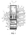
- FIG. 1 an exemplary embodiment of a transfer device 2 according to the present invention can be seen in an open state of the transport packaging.
- the transfer device according to the present invention is intended to be interposed between a transport packaging 4 and a storage device 6.
- the transport packaging 4 comprises a body 8 provided with a cylindrical cavity 10 for receiving a case X10 axis.
- the cylindrical cavity 10 opens on either side of the cylindrical body by a first end (not shown) and a second one. longitudinal end.
- the second end 10.1 is closed by a removable tape 12, and the first end (not shown).
- the storage device 6 comprises a body 11, in which are formed cylindrical housings 14, 16, 18 of axis X14, X16, X16 parallel to each other. Each housing 14, 16, 18 opens on a front face 20 of the storage device 6 and is closed by a tape 24, 26, 28 respectively.
- the storage device with three housings is given by way of example, it may comprise more or less than three housings, which can be distributed vertically and / or horizontally.
- the transfer device 2 comprises a body of longitudinal axis Y intended to be orthogonal to the axes X10, X14, X16, X18.
- the body comprises a sealed envelope 23 formed by walls 26 at the longitudinal ends formed by panels, and lateral flanges 27, 30 front and rear respectively.
- the panels of the walls 26 are, for example welded to ensure a seal at the longitudinal ends.
- the lateral flanges 27, 30, in the example shown comprise removable panels to allow maintenance of the transfer device 2.
- the mounting of the panels is obtained for example by means of O-rings (not shown).
- the envelope 23 defines a sealed cavity 32 in which is slidably mounted a slide 34 along the axis Y.
- the drawer 34 is never in contact with the external environment.
- the drawer 34 has three compartments C1, C2, C3 each comprising a cylindrical passage 25, 27, 29 of axis XC1, XC2, XC3 respectively.
- the axes XC1, XC2, XC3 are parallel to each other and orthogonal to the Y axis.
- the transfer device comprises on each of its lateral faces 27, 30 inflatable seals 35, 37 intended to come into contact with the longitudinal end face of the transport packaging 4.
- Any other means capable of ensuring a seal between the transfer device and the transport packaging and the storage device could be suitable, for example O-rings or flexible sleeves.
- Each seal 35, 37 has for example a circular shape so as to border the periphery of the open end 10.1 of the cavity 10 and the open end of a housing 14, 16, 18. Thus the seals 35, 37 provide a continuous containment.
- the front flanges 27 and rear 30 respectively comprise an opening 31, 33 of diameter allowing the passage of the tapes 12, 24, 26, 28, the openings 31, 33 are aligned along an axis orthogonal to the Y axis.
- C1 compartment comprises means 36 for allowing the removal of the sealing tape 12 of the transport packaging 4 and means 38 to allow the removal of the transport tape 24, 26, 28 housing 14, 16, 18 .
- the withdrawal means 36, 38 are of similar design, only the withdrawal means 36 will be described in detail.
- the withdrawal means 36 comprise a cylinder 40 movable along the axis XC1 and provided with means 42 for hooking onto the tape 12 of the transport packaging 4.
- these attachment means 42 are of the bayonet type or clamp type.
- a free end of the jack 40 comprises at least one pin capable of cooperating with a corresponding pin on an outer face 12.1 of the tape 12 by rotation. The jack 40 moves in the direction indicated by the reference F1 to come dock the tape 12.
- the jack 40 is advantageously a pneumatic cylinder whose compressed air supply is made from a nacelle which will be described later.
- An electrically moved cylinder could also be considered.
- the inside diameter of the passage 25 is at least equal to the outside diameter of the taps 12, 24, 26, 28 to allow storing steps 12, 24, 26, 28 in compartment C1.
- the withdrawal means 38 symmetrically comprise a jack 43, mounted head-to-tail with respect to the jack 40 and operating symmetrically with respect to a plane P orthogonal to the axis XC1.
- the cylinder 43 moves in the direction of the arrow F2 to come dock the tape 24, 26, 28 and moves in the direction F1 to remove it and allow access to the housing 14, 16, 18.
- steps 14, 16, 18 and vice versa no contamination carried by step 12 can be transferred to steps 14, 16, 18 and vice versa.
- the withdrawals of tape 12 and one of the steps of the storage device may be successive or simultaneous.
- the compartment C1 thus allows the removal and storage of the steps of the transport packaging and the storage device and their storage.
- the compartment C2 comprises withdrawal means 50 of a plug 54, 56, 58 mounted in each housing 14, 16, 18 behind the steps 24, 26, 28 to form an additional biological barrier.
- the withdrawal means 50 also comprise a jack 52 movable axially along the axis XC2 and adapted to hook by a free end on the outer face of the plug 54, 56, 58.
- the attachment may be, for example bayonet type or clamp type.
- the inside diameter of the passage 27 of the compartment C2 is substantially equal to the outside diameter of the biological protection plug 54, 56, 58, to allow it to be housed in the compartment C2.
- the compartment C2 thus allows the removal of the biological protection cap 54, 56, 58 from the housing of the storage device and its storage.
- the compartment C3 has an empty cylindrical passage to allow the sliding of the case of the cavity 10 of the transport device to the housing 14, 16, 18 of the storage device.
- the inside diameter of the passage 29 is substantially equal to that of the cavity 10 and the housings 14, 16, 18 in order to achieve a smooth movement of the case, so when the axis X10 of the cavity 10, the axis XC3 of the compartment C3 and the axis X14 or X16 or X18 are aligned, the cavity 10, the passage 29 and the housing 14, 16, 18 form a channel having a substantially continuous cylindrical wall. The risks of shock are therefore reduced.
- the drawer 34 is advantageously moved by an electric motor and a rack system.
- a pneumatic motor can also be envisaged.
- a continuity of the biological barrier is perfectly ensured by forming a sealed passage for the transfer of the case and ensuring the confinement of the biological protection steps and plugs, any transfer with the external environment being avoided .
- the present invention is also intended to check the tightness of the contact between the inflatable seals 35, 37 and the transport packaging and the storage device respectively by means well known to those skilled in the art, such as with pressure rise. Vacuum is made in the area defined by the inflatable seal supposed to be sealed and the pressure is checked. In the event of an increase, the contact is not sealed and maintenance is required.
- the transfer device according to the present invention is, for example intended to be mounted on a nacelle (not shown) on which will be deposited the transport package 4 in contact with the front flange 27 of the transfer device, so as to align the X10 axis of the cavity 10 with the axis of the opening 31 provided in the front flange 27.
- removable connecting means (not shown) between the package 4 and the transfer device 2 are provided to prevent movement between them.
- the nacelle can, for its part, move horizontally and vertically in order to align the axis of the opening made in the rear flange of the transfer device 2 with an axis X 14, X 16, X 18 of a housing 14, 16, 18 respectively of the storage device 6.
- Removable connecting means (not shown) between the storage device and the transfer device are also advantageously provided to prevent movement between them.
- the transfer device 2 is fixed on the storage device 6, during the transfer operations of the case. Moreover, it is supported by the nacelle. For this, the nacelle is moved towards the storage device 6 until the rear flange 30 is arranged parallel to the front face of the storage device 6, so that the inflatable seal 37 comes into contact with the storage device 6. the front of the storage device 6. Before the inflation of the seal 37, the axis of the rear opening 33 is aligned with that of the housing 14.
- the transport packaging loaded with a case is disposed on the platform of the nacelle so as to align the axis X10 of the cavity 10 and the axis of the front opening 31, guide means can be provided for this purpose. effect on the platform of the nacelle.
- the package can be placed on the platform before it reaches the storage device.
- the end face of the transport packaging 4 is placed sufficiently close to the front flange 27 so that the inflatable seal 35 carried by the front flange 27 comes into contact with the end face of the transport packaging 4 and forms a tight zone around the front opening 31.
- the inflation of the seal 35 is performed after the introduction of the transport packaging 4.
- the spool 34 is then moved along the axis Y, so as to align the axis XC1 of the compartment C1 with those of the front openings 31 and rear 33.
- the withdrawal means 36, 38 of the taps are successively or simultaneously operated to remove the taps 12 and 24 as can be seen on the figure 1 .
- the spool 34 is moved up the Y axis until the XC2 axis is aligned with the X14 axes.
- the withdrawal means are then actuated and the biological protection plug is removed and stored in the passage 27, as shown in FIG. figure 2 .
- the drawer 34 is further moved upward to align the XC3 axis with the X10 and X14 axes.
- the case is then moved from the cavity 10 to the housing 14 by sliding, for example by means of a jack coming to apply a thrust force on the case. Traction means could be envisaged passing through the housing 14 and the passage 29 and coming to hang on the case.
- the transfer device is disengaged from the storage device, the nacelle is then released.
- Control means are provided inside the transfer device, these are advantageously visual, for example of the camera type, to check the position of the jacks and the state of withdrawal of the tapes and the biological protection plugs.
- the control of the drawer 34 is performed by an operator who orders the sliding of the drawer 34 after having validated the end of the operation in progress.
- a transfer device having only two compartments, the compartment for removing the tape from the transport packaging and the tape of the housing of the storage device, and the compartment for the transfer of the case is not beyond the scope of the present invention.
- a transfer device in which the removal of the tape 12 and the removal of the tape 24, 26, 28 would take place in two separate compartments also does not fall outside the scope of the present invention.
- a transfer device comprising more than three compartments and / or having compartments providing other functions also does not fall outside the scope of the present invention.
Abstract
Description
La présente invention se rapporte à un dispositif pour transférer du combustible nucléaire entre un emballage de transport et un dispositif d'entreposage, et en particulier un étui chargé de combustible nucléaire usé.The present invention relates to a device for transferring nuclear fuel between a transport packaging and a storage device, and in particular a case containing spent nuclear fuel.
Dans le cadre de la gestion des combustibles irradiés, après leur utilisation en réacteur, ceux-ci sont entreposés dans une piscine pour leur refroidissement avant leur évacuation vers un dispositif d'entreposage en attente d'un exutoire définitif, qui peut être le retraitement ou le stockage à long terme.As part of the management of irradiated fuels, after their use in the reactor, they are stored in a pool for cooling before their evacuation to a storage device waiting for a definitive outlet, which may be reprocessing or long-term storage.
Le combustible irradié qui peut être sous forme de crayon est stocké dans des étuis étanches formant une première barrière biologique.The irradiated fuel that can be in pencil form is stored in sealed cases forming a first biological barrier.
Ces étuis sont alors destinés à être transportés dans un emballage de transport jusqu'à un lieu de stockage comportant un logement d'entreposage permettant le refroidissement du combustible.These cases are then intended to be transported in a transport packaging to a storage location having a storage housing for cooling the fuel.
Un tel transfert d'un étui de l'emballage de transport vers le dispositif d'entreposage ou inversement du dispositif d'entreposage vers l'emballage de transport est connu du document
Il est également connu des documents
C'est par conséquent un but de la présente invention d'offrir un dispositif de transfert d'un étui de combustible nucléaire entre un emballage de transport et un dispositif d'entreposage formant une barrière biologique continue entre le combustible nucléaire et l'environnement extérieur.It is therefore an object of the present invention to provide a device for transferring a nuclear fuel case between a transport package and a storage device forming a continuous biological barrier between the nuclear fuel and the external environment. .
Le but précédemment énoncé est atteint par un dispositif comportant un corps dans lequel est monté mobile un tiroir multifonctionnel apte à assurer les fonctions de retrait des bouchons de l'emballage de transport d'une part, et du dispositif d'entreposage d'autre part, et de transfert de l'étui entre l'emballage de transport et le dispositif d'entreposage.The previously stated purpose is achieved by a device comprising a body in which is mounted movable a multifunctional drawer adapted to perform the functions of removing the plugs of the transport packaging on the one hand, and the storage device on the other hand , and transfer of the case between the transport packaging and the storage device.
En d'autres termes, le dispositif de transfert forme une vanne tiroir de grande taille, au moins un étage du tiroir permettant d'ouvrir l'emballage de transport et le dispositif d'entreposage, et un autre étage du tiroir permettant le transfert effectif de l'étui de l'emballage de transport au dispositif de transfert et vice-versa.In other words, the transfer device forms a large slide valve, at the at least one stage of the drawer for opening the transport packaging and the storage device, and another stage of the drawer for the effective transfer of the case of the transport packaging to the transfer device and vice versa.
Ainsi, l'environnement extérieur n'est jamais en contact ni avec l'étui, ni avec l'intérieur du dispositif d'entreposage, ni avec celui de l'emballage de transport, le dispositif de transfert assurant le confinement et limitant la fuite des contaminations.Thus, the external environment is never in contact with the case, nor with the interior of the storage device, nor with that of the transport packaging, the transfer device ensuring the confinement and limiting the leakage contaminations.
Le dispositif de transfert forme en lui-même une protection biologique. Celui-ci comporte par ailleurs des dispositifs d'étanchéité permettant de réaliser ses opérations de chargement et de déchargement des dispositifs de stockage sans rupture de confinement.The transfer device itself forms a biological protection. It also comprises sealing devices for carrying out its operations of loading and unloading storage devices without breaking confinement.
Le dispositif selon l'invention permet par ailleurs l'ouverture d'un emballage de transport et du dispositif d'entreposage sans rupture de confinement, sans nécessité de protection biologique supplémentaire et sans intervention humaine directe.The device according to the invention also allows the opening of a transport packaging and the storage device without breach of confinement, without the need for additional biological protection and without direct human intervention.
Le dispositif de transfert selon la présente invention permet de manière particulièrement avantageuse de réaliser un chargement ou un déchargement à l'air libre ; il n'est pas nécessaire de prévoir de réaliser ces manipulations dans un endroit clos, le dispositif de transfert assurant en combinaison avec l'emballage de transport et le dispositif d'entreposage le confinement nécessaire et suffisant de l'étui.The transfer device according to the present invention makes it particularly advantageous to carry out loading or unloading in the open air; it is not necessary to provide for these manipulations in an enclosed area, the transfer device ensuring in combination with the transport packaging and the storage device the necessary and sufficient confinement of the case.
Par ailleurs, ce dispositif de transfert présente l'avantage d'être portatif et donc d'être utilisé pour le chargement de tous les logements d'une station de stockage. Ceci réduit en outre le coût du stockage.Furthermore, this transfer device has the advantage of being portable and therefore to be used for loading all the slots of a storage station. This further reduces the cost of storage.
La présente invention a alors principalement pour objet un dispositif de transfert d'un étui de combustible nucléaire entre un emballage de transport dudit étui et un dispositif d'entreposage dudit étui, ledit emballage comportant une cavité cylindrique de réception de l'étui et une ouverture obturée par une tape de transport pour le chargement/déchargement de l'étui, ledit dispositif d'entreposage comportant au moins un logement pour recevoir ledit étui et une ouverture obturée par une tape de stockage pour le chargement/déchargement dudit étui, lequel dispositif de transfert comportant un corps et un tiroir d'axe longitudinal, apte à coulisser dans ledit corps selon son axe longitudinal, ledit tiroir comportant au moins un premier compartiment pour retirer une tape de l'emballage de transport et une tape du dispositif d'entreposage et un deuxième compartiment pour permettre le passage de l'étui de l'emballage de transport au dispositif d'entreposage et inversement, et des moyens pour rendre étanche le transfert entre l'emballage de transport et le dispositif de transfert et entre le dispositif de transfert et le dispositif d'entreposage.The main subject of the present invention is therefore a device for transferring a nuclear fuel case between a transport packaging of said case and a device for storing said case, said package comprising a cylindrical cavity for receiving the case and an opening. closed by a transport tape for loading / unloading the case, said storage device comprising at least one housing for receiving said case and an opening closed by a storage tape for loading / unloading said case, which device transfer comprising a body and a drawer of longitudinal axis, able to slide in said body along its longitudinal axis, said drawer having at least a first compartment for removing a tape from the transport packaging and a tape of the storage device and a second compartment to allow the passage of the case of the transport packaging to the storage device and vice versa, and means for sealing the transfer between the transport package and the transfer device and between the transfer device and the storage device.
Dans un exemple particulièrement avantageux, le dispositif de transfert selon l'invention comporte également un compartiment intermédiaire entre le premier et le deuxième compartiment, comportant un passage dans lequel sont montés des moyens de retrait d'un bouchon de protection biologique contenu dans le dispositif d'entreposage en arrière de la tape, ledit bouchon étant stocké dans ledit passage.In a particularly advantageous example, the transfer device according to the invention also comprises a compartment intermediate between the first and second compartment, having a passage in which are mounted means for removing a biological protection plug contained in the storage device back of the tape, said plug being stored in said passage.
Le premier compartiment peut comporter un passage axial dans lequel sont montés des premiers moyens de retrait de la tape de l'emballage de transport et des deuxièmes moyens de retrait de la tape du dispositif d'entreposage, lesdits moyens de retrait étant du type à baïonnette ou à pince, montés à coulissement dans ledit passage, lesdites tapes étant stockées dans ledit passage lors du retrait.The first compartment may comprise an axial passage in which are mounted first means for removing the tape from the transport packaging and second means for removing the tape from the storage device, the said withdrawal means being of the bayonet type. or clamp, slidably mounted in said passage, said tapes being stored in said passage during removal.
Dans un exemple de réalisation, les premiers moyens de retrait et les deuxièmes moyens de retrait sont montés tête-bêche, et sont montés dans deux chambres isolées l'une de l'autre. Ce qui permet de réaliser un tiroir compact et évite un transfert de contamination entre les tapes.In an exemplary embodiment, the first withdrawal means and the second withdrawal means are mounted head to tail, and are mounted in two chambers isolated from each other. This allows for a compact drawer and avoids a transfer of contamination between the tapes.
Le deuxième compartiment peut comporter un passage de diamètre supérieur à celui d'un étui pour permettre le transfert d'un étui entre l'emballage de transport et le dispositif d'entreposage par ledit passage, ledit diamètre étant sensiblement égal à celui de la cavité de l'emballage de transport et à celui du logement du dispositif d'entreposage, ceci permettant de limiter les chocs sur l'étui lors de son transfert.The second compartment may include a passage of diameter greater than that of a case to allow the transfer of a case between the transport packaging and the storage device through said passage, said diameter being substantially equal to that of the cavity transport packaging and that of the housing of the storage device, this to limit shocks on the case during its transfer.
Le corps du dispositif de transfert peut comporter une enveloppe définissant un espace intérieur étanche dans lequel le tiroir peut coulisser, ladite enveloppe comportant des flasques latéraux munis chacun d'une ouverture destinée à être en regard de la cavité de l'emballage de transport et une ouverture destinée à être en regard du logement du dispositif d'entreposage, et lesdits moyens pour rendre étanche le transfert comportant deux joints gonflables solidaires des flasques latéraux entourant de manière continue chacune des ouvertures, et destinés à venir chacun en contact avec une face d'extrémité de l'emballage de transport et avec une face d'extrémité du dispositif d'entreposage respectivement.The body of the transfer device may comprise an envelope defining a sealed interior space in which the slide can slide, said envelope comprising lateral flanges each provided with an opening intended to face the cavity of the transport packaging and an opening intended to face the housing of the storage device, and said means for sealing the transfer comprising two inflatable seals integral side flanges continuously surrounding each of the openings, and intended to come each in contact with an end face of the transport package and with an end face of the storage device respectively.
Les flasques latéraux comportent avantageusement des panneaux amovibles permettant la maintenance, lesdits panneaux étant montés de manière étanche afin d'assurer l'étanchéité de l'enveloppe.The lateral flanges advantageously comprise removable panels for maintenance, said panels being mounted in a sealed manner to seal the envelope.
Par exemple, le tiroir est déplacé au moyen d'un moteur électrique.For example, the drawer is moved by means of an electric motor.
Les moyens de retrait sont par exemple actionnés par air comprimé, ce qui permet d'éviter les pollutions par de l'huile.The withdrawal means are for example actuated by compressed air, which makes it possible to avoid pollution by oil.
La présente invention a également pour objet un procédé de transfert d'un étui de combustible nucléaire entre un emballage de transport et un dispositif d'entreposage au moyen d'un dispositif de transfert comportant un tiroir muni d'au moins un premier compartiment pour le retrait de tapes de l'emballage de transport et du dispositif d'entreposage, d'un deuxième compartiment pour le passage de l'étui et des moyens d'étanchéité entre le dispositif de transfert et l'emballage de transport et le dispositif d'entreposage, ledit procédé comportant les étapes :
- a) d'alignement du dispositif de transfert avec l'emballage de transport et le dispositif d'entreposage,
- b) d'alignement du premier compartiment du tiroir avec là cavité de l'emballage de transport et un logement du dispositif d'entreposage par déplacement du tiroir,
- c) de retrait de la tape de transport et de la tape de stockage,
- d) d'alignement du deuxième compartiment avec la cavité de l'emballage de transport et ledit logement du dispositif d'entreposage par déplacement du tiroir,
- e) de coulissement de l'étui entre le dispositif d'entreposage et l'emballage de transport.
- a) alignment of the transfer device with the transport packaging and the storage device,
- b) aligning the first compartment of the drawer with the cavity of the transport packaging and a housing of the storage device by moving the drawer,
- (c) removal of the transport tape and storage tape,
- d) aligning the second compartment with the cavity of the transport package and said housing of the storage device by moving the drawer,
- e) sliding of the case between the storage device and the transport packaging.
Avantageusement, le procédé selon l'invention comporte une étape c') d'alignement d'un compartiment intermédiaire avec la cavité de l'emballage de transport et ledit logement du dispositif d'entreposage par déplacement du tiroir, et une étape c'') de retrait d'un bouchon contenu dans ledit logement en retrait de la tape de stockage.Advantageously, the method according to the invention comprises a step c ') of aligning an intermediate compartment with the cavity of the transport packaging and said housing of the storage device by moving the drawer, and a step c' '. ) removal of a plug contained in said recess of the storage tape.
Le procédé peut également comporter une étape de gonflage de joints portés par le dispositif et en contact avec l'emballage de transport et le dispositif d'entreposage pour assurer un contact étanche entre le dispositif de transfert et l'emballage de transport et le dispositif d'entreposage.The method may also include a step of inflating seals carried by the device and in contact with the transport packaging and the storage device to ensure a sealing contact between the transfer device and the transport packaging and the device of the device. 'storage.
Lors de l'étape a), il peut également être prévu un accrochage du dispositif de transfert sur le dispositif d'entreposage et sur l'emballage de transport.During step a), it can also be provided a hooking of the transfer device on the storage device and on the transport packaging.
La présente invention sera mieux comprise à l'aide de la description qui va suivre et des dessins annexés, sur lesquels :
- la
figure 1 est une vue en coupe longitudinale d'un dispositif de transfert selon la présente invention dans une première position, - la
figure 2 est une vue du dispositif de transfert de lafigure 1 dans une deuxième position, - la
figure 3 est une vue du dispositif de transfert de lafigure 1 dans une troisième position.
- the
figure 1 is a longitudinal sectional view of a transfer device according to the present invention in a first position, - the
figure 2 is a view of the transfer device of thefigure 1 in a second position, - the
figure 3 is a view of the transfer device of thefigure 1 in a third position.
Sur la
Le dispositif de transfert selon la présente invention est destiné à être interposé entre un emballage de transport 4 et un dispositif d'entreposage 6.The transfer device according to the present invention is intended to be interposed between a
L'emballage de transport 4 comporte un corps 8 muni d'une cavité cylindrique 10 pour recevoir un étui d'axe X10. La cavité cylindrique 10 débouche de part et d'autre du corps cylindrique par une première extrémité (non représentée) et une deuxième 10.1 extrémité longitudinale. La deuxième extrémité 10.1 est obturée par une tape 12 amovible, ainsi que la première extrémité (non représentée).The
Le dispositif d'entreposage 6 comporte un corps 11, dans lequel sont réalisés des logements cylindriques 14, 16, 18 d'axe X14, X16, X16 parallèles entre eux. Chaque logement 14, 16, 18 débouche sur une face avant 20 du dispositif d'entreposage 6 et est obturé par une tape 24, 26, 28 respectivement. Le dispositif d'entreposage avec trois logements est donné à titre d'exemple, celui-ci peut comporter plus ou moins de trois logements, qui peuvent être répartis verticalement et/ou horizontalement.The
Le dispositif de transfert 2 comporte un corps d'axe longitudinal Y destiné à être orthogonal aux axes X10, X14, X16, X18.The
Le corps comporte une enveloppe étanche 23 formée par des parois 26 aux extrémités longitudinales formées par des panneaux, et des flasques latéraux 27, 30 avant et arrière respectivement.The body comprises a sealed
Les panneaux des parois 26 sont, par exemple soudés afin d'assurer une étanchéité aux extrémités longitudinales.The panels of the
Les flasques latéraux 27, 30, dans l'exemple représenté comportent des panneaux amovibles pour permettre la maintenance du dispositif de transfert 2. L'étanchéité de montage des panneaux est obtenue par exemple au moyen de joints toriques (non représentés).The
L'enveloppe 23 délimite une cavité 32 étanche dans laquelle est monté à coulissement un tiroir 34 le long de l'axe Y.The
Le tiroir 34 n'est donc jamais en contact avec l'environnement extérieur.The
Le tiroir 34 comporte trois compartiments C1, C2, C3 comprenant chacun un passage cylindrique 25, 27, 29 d'axe XC1, XC2, XC3 respectivement. Les axes XC1, XC2, XC3 sont parallèles entre eux et orthogonaux à l'axe Y.The
De manière avantageuse, le dispositif de transfert comporte sur chacune de ses faces latérales 27, 30 des joints gonflables 35, 37 destinés à venir en contact avec la face d'extrémité longitudinale de l'emballage de transport 4.Advantageously, the transfer device comprises on each of its lateral faces 27, 30
Tout autre moyen apte à assurer une étanchéité entre le dispositif de transfert et l'emballage de transport et le dispositif d'entreposage pourrait convenir, par exemple des joints toriques ou des manchons souples.Any other means capable of ensuring a seal between the transfer device and the transport packaging and the storage device could be suitable, for example O-rings or flexible sleeves.
Chaque joint 35, 37 a par exemple une forme circulaire de façon à border la périphérie de l'extrémité ouverte 10.1 de la cavité 10 et l'extrémité ouverte d'un logement 14, 16, 18. Ainsi les joints 35, 37 assurent un confinement continu.Each
Les flasques avant 27 et arrière 30 comportent respectivement une ouverture 31, 33 de diamètre permettant le passage des tapes 12, 24, 26, 28, les ouvertures 31, 33 sont alignés selon un axe orthogonal à l'axe Y.The
Le compartiment C1 comporte des moyens 36 pour permettre le retrait de la tape d'obturation 12 de l'emballage de transport 4 et des moyens 38 pour permettre le retrait de la tape de transport 24, 26, 28 du logement 14, 16, 18.C1 compartment comprises means 36 for allowing the removal of the sealing
Les moyens de retrait 36, 38 sont de réalisation semblable, seuls les moyens de retrait 36 seront décrits de manière détaillée.The withdrawal means 36, 38 are of similar design, only the withdrawal means 36 will be described in detail.
Les moyens de retrait 36 comportent un vérin 40 mobile selon l'axe XC1 et muni de moyens 42 pour s'accrocher à la tape 12 de l'emballage de transport 4. Par exemple ces moyens d'accrochage 42 sont du type à baïonnette ou du type à pince. Par exemple une extrémité libre du vérin 40 comporte au moins un pion apte à venir coopérer avec un pion correspondant sur une face extérieure 12.1 de la tape 12 par rotation. Le vérin 40 se déplace dans le sens indiqué par la référence F1 pour venir accoster la tape 12.The withdrawal means 36 comprise a
Lorsque l'accrochage du vérin 40 sur la tape 12 est effectué, celui-ci coulisse dans la direction opposée selon la flèche F2, retirant la tape 12 de l'extrémité de la cavité 10 et libérant l'accès à la cavité 10.When the attachment of the
Le vérin 40 est avantageusement un vérin pneumatique dont l'alimentation air comprimé est réalisée à partir d'une nacelle qui sera décrite plus tard. Un vérin déplacé électriquement pourrait également être envisagé.The
Le diamètre intérieur du passage 25 est au moins égal au diamètre extérieur des tapes 12, 24, 26, 28 pour permettre l'entreposage des tapes 12, 24, 26, 28 dans le compartiment C1.The inside diameter of the
Les moyens de retrait 38 comportent de manière symétrique un vérin 43, monté tête-bêche par rapport au vérin 40 et fonctionnant de manière symétrique par rapport à un plan P orthogonal à l'axe XC1. Ainsi le vérin 43 se déplace dans le sens de la flèche F2 pour venir accoster la tape 24, 26, 28 et se déplace dans le sens F1 pour la retirer et permettre l'accès au logement 14, 16, 18.The withdrawal means 38 symmetrically comprise a
De manière avantageuse, il est prévu une paroi 44 pour isoler les moyens de retrait 36 et les moyens de retrait 38 de manière à délimiter deux chambres 46, 48 séparées de manière étanche l'une de l'autre. Ainsi aucune contamination portée par la tape 12 ne peut être transférée aux tapes 14, 16, 18 et inversement.Advantageously, there is provided a
Les retraits de la tape 12 et de l'une des tapes du dispositif d'entreposage peuvent être successifs ou simultanés.The withdrawals of
Le compartiment C1 permet donc le retrait et le stockage des tapes de l'emballage de transport et du dispositif d'entreposage et leur entreposage.The compartment C1 thus allows the removal and storage of the steps of the transport packaging and the storage device and their storage.
Le compartiment C2 comporte des moyens de retrait 50 d'un bouchon 54, 56, 58 monté dans chaque logement 14, 16, 18 en arrière des tapes 24, 26, 28 afin de former une barrière biologique supplémentaire.The compartment C2 comprises withdrawal means 50 of a
Les moyens de retrait 50 comportent également un vérin 52 mobile axialement le long de l'axe XC2 et apte à venir s'accrocher par une extrémité libre sur la face extérieure du bouchon 54, 56, 58.The withdrawal means 50 also comprise a
L'accrochage peut être, par exemple du type à baïonnette ou du type à pince.The attachment may be, for example bayonet type or clamp type.
Le diamètre intérieur du passage 27 du compartiment C2 est sensiblement égal au diamètre extérieur du bouchon de protection biologique 54, 56, 58, pour permettre son logement dans le compartiment C2.The inside diameter of the
Le compartiment C2 permet donc le retrait du bouchon de protection biologique 54, 56, 58 du logement du dispositif d'entreposage et son entreposage.The compartment C2 thus allows the removal of the
On peut également prévoir des moyens similaires à ceux du compartiment C1 dans le cas où l'emballage de transport comporte un bouchon identique ou similaire à celui 54, 56, 58 du dispositif d'entreposage.It is also possible to provide means similar to those of compartment C1 in the case where the transport packaging comprises a plug identical or similar to that 54, 56, 58 of the storage device.
Le compartiment C3 comporte un passage cylindrique vide pour permettre le coulissement de l'étui de la cavité 10 du dispositif de transport vers le logement 14, 16, 18 du dispositif d'entreposage.The compartment C3 has an empty cylindrical passage to allow the sliding of the case of the
Le diamètre intérieur du passage 29 est sensiblement égal à celui de la cavité 10 et des logements 14, 16, 18 afin de réaliser un déplacement sans heurt de l'étui, ainsi lorsque l'axe X10 de la cavité 10, l'axe XC3 du compartiment C3 et l'axe X14 ou X16 ou X18 sont alignés, la cavité 10, le passage 29 et le logement 14, 16, 18 forment un canal ayant une paroi cylindrique sensiblement continue. Les risques de choc sont donc réduits.The inside diameter of the
Le tiroir 34 est avantageusement déplacé par un moteur électrique et un système à crémaillère. Un moteur pneumatique peut également être envisagé.The
Grâce à la présente invention, une continuité de la barrière biologique est donc parfaitement assurée en formant un passage étanche pour le transfert de l'étui et en assurant le confinement des tapes et bouchons de protection biologique, tout transfert avec l'environnement extérieur étant évité.Thanks to the present invention, a continuity of the biological barrier is perfectly ensured by forming a sealed passage for the transfer of the case and ensuring the confinement of the biological protection steps and plugs, any transfer with the external environment being avoided .
Selon la présente invention, il est également prévu de vérifier l'étanchéité du contact entre les joints gonflables 35, 37 et l'emballage de transport et le dispositif d'entreposage respectivement par des moyens bien connus de l'homme du métier, du type à remontée de pression. On réalise le vide dans la zone délimitée par le joint gonflable censée être étanche et on vérifie la pression. En cas d'augmentation de celle-ci, le contact n'est pas étanche et une maintenance est requise.According to the present invention, it is also intended to check the tightness of the contact between the
Par ailleurs, il est prévu une vérification du montage étanche des flasques du corps lors du montage de ceux-ci.Furthermore, it is provided a verification of the sealed mounting of the flanges of the body during assembly thereof.
Le dispositif de transfert selon la présente invention est, par exemple destiné à être monté sur une nacelle (non représentée) sur laquelle sera déposé l'emballage de transport 4 en contact du flasque avant 27 du dispositif de transfert, de manière à aligner l'axe X10 de la cavité 10 avec l'axe de l'ouverture 31 prévue dans le flasque avant 27.The transfer device according to the present invention is, for example intended to be mounted on a nacelle (not shown) on which will be deposited the
Ainsi le dispositif de transfert 2 et l'emballage de transport 4 sont immobiles l'un par rapport à l'autre.Thus the
Avantageusement, des moyens de liaison amovibles (non représentés) entre l'emballage 4 et le dispositif de transfert 2 sont prévus pour éviter tout mouvement entre eux.Advantageously, removable connecting means (not shown) between the
La nacelle peut, quant à elle, se déplacer horizontalement et verticalement afin d'aligner l'axe de l'ouverture pratiquée dans le flasque arrière du dispositif de transfert 2 avec un axe X14, X16, X18 d'un logement 14, 16, 18 respectivement du dispositif d'entreposage 6. Des moyens de liaison amovibles (non représentés) entre le dispositif d'entreposage et le dispositif de transfert sont également prévus, de manière avantageuse, pour éviter tout mouvement entre eux.The nacelle can, for its part, move horizontally and vertically in order to align the axis of the opening made in the rear flange of the
Nous allons maintenant expliquer le fonctionnement du dispositif de transfert selon la présente invention. A titre d'exemple non limitatif, nous considérons que l'on souhaite stocker l'étui dans le logement 14.We will now explain the operation of the transfer device according to the present invention. By way of non-limiting example, we consider that it is desired to store the case in the
De manière avantageuse, le dispositif de transfert 2 est fixé sur le dispositif d'entreposage 6, durant les opérations de transfert de l'étui. Par ailleurs, il est supporté par la nacelle. Pour cela la nacelle est déplacée en direction du dispositif d'entreposage 6 jusqu'à ce que le flasque arrière 30 soit disposé parallèlement à la face avant du dispositif d'entreposage 6, de manière à ce que le joint gonflable 37 vienne en contact avec la face avant du dispositif d'entreposage 6. Avant le gonflage du joint 37, l'axe de l'ouverture arrière 33 est aligné avec celui du logement 14.Advantageously, the
L'emballage de transport chargé d'un étui est disposé sur le plateau de la nacelle de manière à aligner l'axe X10 de la cavité 10 et l'axe de l'ouverture avant 31, des moyens de guidage peuvent être prévus à cet effet sur le plateau de la nacelle. L'emballage peut être disposé sur la nacelle avant que celle-ci n'accoste le dispositif d'entreposage.The transport packaging loaded with a case is disposed on the platform of the nacelle so as to align the axis X10 of the
La face d'extrémité de l'emballage de transport 4 est placé suffisamment près du flasque avant 27, pour que le joint gonflable 35 porté par le flasque avant 27 vienne en contact avec la face d'extrémité de l'emballage de transport 4 et forme une zone étanche autour de l'ouverture avant 31. Le gonflage du joint 35 est effectué après la mise en place de l'emballage de transport 4.The end face of the
Le tiroir 34 est alors déplacé selon l'axe Y, de manière à aligner l'axe XC1 du compartiment C1 avec ceux des ouvertures avant 31 et arrière 33.The
Les moyens de retrait 36, 38 des tapes sont successivement ou simultanément actionnés pour retirer les tapes 12 et 24 comme on peut le voir sur la
Ensuite le tiroir 34 est déplacé selon l'axe Y vers le haut jusqu'à ce que l'axe XC2 soit aligné avec les axes X14. Les moyens de retrait sont alors actionnés et le bouchon de protection biologique est retiré et stocké dans le passage 27, comme cela est représenté sur la
Le tiroir 34 est encore déplacé vers le haut pour aligner l'axe XC3 avec les axes X10 et X14. L'étui est ensuite déplacé de la cavité 10 vers le logement 14 par coulissement, par exemple au moyen d'un vérin venant appliquer un effort de poussée sur l'étui. On pourrait envisager des moyens de traction traversant le logement 14 et le passage 29 et venant s'accrocher sur l'étui.The
Lorsque l'étui est disposé dans le logement 14, les étapes de remise en place du bouchon de protection biologique puis des tapes sont réalisées de manière inverse à celles décrites ci-dessus.When the case is disposed in the
Pour le chargement des autres logements 16, 18, le même mode opératoire est effectué.For the loading of the
Pour le retrait des étuis des logements 14, 16, 18 on opère de la même manière sauf que, lorsque le compartiment C3 est aligné avec la cavité 10 et le logement concerné, l'étui est transféré du logement du dispositif d'entreposage vers l'emballage de transport.For the removal of the cases of the
A l'issue de l'opération de transfert, le dispositif de transfert est désolidarisé du dispositif d'entreposage, la nacelle est alors libérée.At the end of the transfer operation, the transfer device is disengaged from the storage device, the nacelle is then released.
Des moyens de contrôle sont prévus à l'intérieur du dispositif de transfert, ceux-ci sont avantageusement visuels, par exemple du type caméra, pour vérifier la position des vérins et l'état de retrait des tapes et des bouchons de protection biologique.Control means are provided inside the transfer device, these are advantageously visual, for example of the camera type, to check the position of the jacks and the state of withdrawal of the tapes and the biological protection plugs.
La commande du tiroir 34 est réalisée par un opérateur qui ordonne le coulissement du tiroir 34 après avoir validé la fin de l'opération en cours.The control of the
De même, c'est l'opérateur qui gère le retrait des tapes et des bouchons, et le transfert de l'étui.Similarly, it is the operator who manages the removal of the taps and caps, and the transfer of the case.
On pourrait également envisager un déroulement automatique des différentes étapes.One could also consider an automatic progress of the different steps.
Dans le cas où le bouchon de protection biologique 54, 56, 58 n'est pas prévu ou est amovible de manière différente, un dispositif de transfert ne comportant que deux compartiments, le compartiment pour le retrait de la tape de l'emballage de transport et la tape du logement du dispositif d'entreposage, et le compartiment pour le transfert de l'étui ne sort pas du cadre de la présente invention.In the case where the
Un dispositif de transfert dans lequel le retrait de la tape 12 et le retrait de la tape 24, 26, 28 s'effectuerait dans deux compartiments séparés ne sort également pas du cadre de la présente invention.A transfer device in which the removal of the
Un dispositif de transfert comportant plus de trois compartiments et/ou comportant des compartiments assurant d'autres fonctions ne sort également pas du cadre de la présente invention.A transfer device comprising more than three compartments and / or having compartments providing other functions also does not fall outside the scope of the present invention.
Le procédé de transfert d'un étui entre le dispositif d'entreposage et l'emballage de transport au moyen du dispositif de transfert selon la présente invention comporte les étapes :
- d'alignement de la cavité 10 et du logement 14 du dispositif d'entreposage à charger ou à décharger avec les ouvertures 31, 33 du dispositif de transfert,
- d'alignement du compartiment C1 avec la cavité 10 et le logement 14,
- de retrait des
tapes - d'alignement du compartiment C2 avec la cavité 10 et le logement 14, si le logement 14
comporte un bouchon 54, - de retrait du bouchon 54, le cas échéant,
- d'alignement du compartiment C3 avec la cavité 10 et le logement 14 et de transfert de l'étui de la cavité 10 vers le logement 14 ou du logement 14 vers la cavité 10.
- aligning the
cavity 10 and thehousing 14 of the storage device to be loaded or unloaded with theopenings - aligning the compartment C1 with the
cavity 10 and thehousing 14, - removing
steps - aligning the compartment C2 with the
cavity 10 and thehousing 14, if thehousing 14 comprises aplug 54, - removing the
plug 54, if necessary, - aligning the compartment C3 with the
cavity 10 and thehousing 14 and transferring the case from thecavity 10 to thehousing 14 or thehousing 14 to thecavity 10.
Il peut être prévu, après la première étape, d'immobiliser le dispositif de transfert sur le dispositif d'entreposage et sur l'emballage de transport.After the first step, it is possible to immobilize the transfer device on the storage device and on the transport packaging.
Nous avons donc bien réalisé un dispositif permettant de transférer de manière sûre du combustible nucléaire contenu dans un étui entre un emballage de transport et un dispositif d'entreposage.We have therefore made a device for safely transferring nuclear fuel contained in a case between a transport package and a storage device.
Claims (13)
- Device (2) for transferring a nuclear fuel canister between a container (4) for transporting said canister and a device (6) for storing said canister, said container (4) comprising a cylindrical cavity (10) for receiving the canister and an opening sealed by a transport plug (12) for the loading/unloading of the canister, said storage device (6) comprising at least one housing (14, 16, 18) to receive said canister and an opening sealed by a storage plug (24, 26, 28) for the loading/unloading of said canister, said transfer device comprising a body and a slide (34) of longitudinal axis, capable of sliding in said body along its longitudinal axis (Y), said slide (34) comprising at least one first compartment (C1) to withdraw the transport plug (12) and the storage plug (24, 26, 28) and a second compartment (C3) for allowing the canister to pass from the transport container (4) to the storage device (6) and conversely, and means (35, 37) for sealing the transfer between the transport container (4) and the transfer device (2) and between the transfer device (2) and the storage device (6).
- Device according to claim 1, also comprising an intermediate compartment (C2) between the first (C1) and the second (C3) compartment, comprising a passage in which are assembled means of withdrawing (50) a biological protection cap (54, 56, 58) contained in the storage device (6) behind the plug (24, 26, 28), said cap (54, 56, 58) being stored in said passage.
- Device according to claim 1 or 2, wherein the first compartment (C1) comprises an axial passage in which are assembled first means of withdrawing (36) the transport plug (12) and second means of withdrawing (38) the storage plug (34, 36, 38), said withdrawal means (36, 38) being of the bayonet or clamp type assembled in a sliding manner in said passage, said plugs (12, 24, 26, 28) being stored in said passage during the withdrawal.
- Device according to the preceding claim, wherein the first withdrawal means (36) and the second withdrawal means (38) are assembled head to tail, and are assembled in two chambers (46, 48) isolated from each other.
- Device according to one of claims 1 to 4, wherein the second compartment (C3) comprises a passage of diameter greater than that of a canister to enable the transfer of a canister between the transport container (4) and the storage device (6) via said passage, said diameter being substantially equal to that of the cavity (10) of the transport container (4) and to that of the housing (14, 16, 18) of the storage device (6).
- Device according to any of claims 1 to 5, wherein the body comprises a jacket (23) defining a sealed interior space in which the slide (34) can slide, said jacket (23) comprising lateral end-plates (27, 30) each provided with an opening (31) intended to be facing the cavity (10) of the transport container (4) and an opening (33) intended to be facing the housing (14, 16, 18) of the storage device (6), and said means (35, 37) for sealing the transfer comprising a first (35) and a second (37) inflatable seal integral with the lateral end-plates (27, 30) surrounding in a continuous manner each of the openings (31, 33), and each intended to come into contact with one end face of the transport container (4) and with one end face of the storage device (6) respectively.
- Device according to the preceding claim, wherein the lateral end-plates (27, 30) comprise removable panels (27.1, 30.1) enabling maintenance, said panels (27.1, 30.1) being assembled in a sealed manner in order to assure the sealing of the jacket.
- Device according to any of claims 1 to 7, wherein the slide (34) is moved by means of an electric motor.
- Device according to any of claims 1 to 8 in combination with claim 3, wherein the withdrawal means (36, 38, 50) are operated by compressed air.
- Method of transferring a nuclear fuel canister between a transport container and a storage device by means of a transfer device comprising a slide provided with at least one first compartment for the withdrawal of plugs from the transport container and the storage device, a second compartment for allowing
the canister and sealing means to pass between the transfer device and the transport container and the storage device, said method comprising the steps of:a) alignment of the transfer device with the transport container and the storage device,b) alignment of the first compartment of the slide with the cavity of the transport container and a housing of the storage device by moving the slide,c) removal of the transport plug and the storage plug,d) alignment of the second compartment with the cavity of the transport container and said housing of the storage device by moving the slide,e) sliding the canister between the storage device and the transport container. - Method of transfer according to claim 10, comprising a step c') of alignment of an intermediate compartment with the cavity of the transport container and said housing of the storage device by moving the slide, and a step c'') of withdrawing a cap contained in said housing set back from the storage plug.
- Method of transfer according to claim 10 or 11, comprising after step a) the step of inflating seals borne by the device and in contact with the transport container and the storage device to assure a sealed contact between the transfer device and the transport container and the storage device.
- Method of transfer according to one of claims 10 to 12, wherein during step a), an attachment of the transfer device to the storage device and to the transport container is provided for.
Applications Claiming Priority (2)
| Application Number | Priority Date | Filing Date | Title |
|---|---|---|---|
| FR0655295A FR2909480B1 (en) | 2006-12-04 | 2006-12-04 | DEVICE FOR TRANSFERRING NUCLEAR FUEL CASES BETWEEN A TRANSPORT PACKAGE AND A STORAGE DEVICE |
| PCT/EP2007/063040 WO2008068190A1 (en) | 2006-12-04 | 2007-11-30 | Device for transferring nuclear fuel cartridges between a transport container and a storage device |
Publications (2)
| Publication Number | Publication Date |
|---|---|
| EP2100309A1 EP2100309A1 (en) | 2009-09-16 |
| EP2100309B1 true EP2100309B1 (en) | 2011-04-06 |
Family
ID=38236436
Family Applications (1)
| Application Number | Title | Priority Date | Filing Date |
|---|---|---|---|
| EP07847556A Not-in-force EP2100309B1 (en) | 2006-12-04 | 2007-11-30 | Device for transferring nuclear fuel cartridges between a transport container and a storage device |
Country Status (7)
| Country | Link |
|---|---|
| US (1) | US8792606B2 (en) |
| EP (1) | EP2100309B1 (en) |
| JP (1) | JP5658877B2 (en) |
| AT (1) | ATE504924T1 (en) |
| DE (1) | DE602007013804D1 (en) |
| FR (1) | FR2909480B1 (en) |
| WO (1) | WO2008068190A1 (en) |
Families Citing this family (6)
| Publication number | Priority date | Publication date | Assignee | Title |
|---|---|---|---|---|
| US20110243293A1 (en) * | 2010-03-31 | 2011-10-06 | Peter Ray Diller | Systems and Methods for Servicing a Fuel Assembly in a Light Water Reactor |
| US20120183375A1 (en) * | 2010-11-19 | 2012-07-19 | Transnuclear, Inc. | Systems, methods, and components for transferring radioactive material |
| US10648823B2 (en) | 2017-06-22 | 2020-05-12 | Aeris Communications, Inc. | Learning common routes and automatic geofencing in fleet management |
| JP2017162956A (en) * | 2016-03-09 | 2017-09-14 | 株式会社村田製作所 | Electronic component and manufacturing method for the same |
| CN108986945A (en) * | 2018-06-11 | 2018-12-11 | 中国核电工程有限公司 | A kind of radioactivity material transfer device |
| FR3084509B1 (en) * | 2018-07-24 | 2021-01-08 | Commissariat Energie Atomique | HANDLING DEVICE FOR FUEL ASSEMBLY AND HANDLING ASSEMBLY INCLUDING SUCH A DEVICE |
Family Cites Families (10)
| Publication number | Priority date | Publication date | Assignee | Title |
|---|---|---|---|---|
| FR1395783A (en) | 1964-03-05 | 1965-04-16 | Commissariat Energie Atomique | Watertight connection device |
| JPS60171493A (en) * | 1984-02-17 | 1985-09-04 | 日立造船株式会社 | Method of housing nuclear fuel to fuel transport vessel and plug for fuel transport vessel |
| US4780269A (en) * | 1985-03-12 | 1988-10-25 | Nutech, Inc. | Horizontal modular dry irradiated fuel storage system |
| DE3717189C1 (en) * | 1987-05-22 | 1988-11-10 | Nuklear Service Gmbh Gns | Device for transferring a radioactive object from a first container into a second container |
| GB9808175D0 (en) * | 1998-04-17 | 1998-06-17 | Coles Timothy P | Rotary gas sanitiser |
| JP2002148387A (en) * | 2000-11-07 | 2002-05-22 | Mitsubishi Heavy Ind Ltd | Storage container and system and method for refilling it |
| RU2192677C1 (en) * | 2001-09-26 | 2002-11-10 | Открытое акционерное общество "ЭМК-Атоммаш" | Haulage lock |
| US6625246B1 (en) * | 2002-04-12 | 2003-09-23 | Holtec International, Inc. | System and method for transferring spent nuclear fuel from a spent nuclear fuel pool to a storage cask |
| JP3970162B2 (en) * | 2002-11-11 | 2007-09-05 | 三菱重工業株式会社 | High-level waste placement equipment during geological disposal |
| JP4285100B2 (en) * | 2003-06-20 | 2009-06-24 | 株式会社Ihi | Refilling facility for horizontal loading of spent nuclear reactor fuel |
-
2006
- 2006-12-04 FR FR0655295A patent/FR2909480B1/en not_active Expired - Fee Related
-
2007
- 2007-11-30 AT AT07847556T patent/ATE504924T1/en not_active IP Right Cessation
- 2007-11-30 DE DE602007013804T patent/DE602007013804D1/en active Active
- 2007-11-30 WO PCT/EP2007/063040 patent/WO2008068190A1/en active Application Filing
- 2007-11-30 JP JP2009538719A patent/JP5658877B2/en not_active Expired - Fee Related
- 2007-11-30 US US12/516,186 patent/US8792606B2/en not_active Expired - Fee Related
- 2007-11-30 EP EP07847556A patent/EP2100309B1/en not_active Not-in-force
Also Published As
| Publication number | Publication date |
|---|---|
| DE602007013804D1 (en) | 2011-05-19 |
| US20100027730A1 (en) | 2010-02-04 |
| ATE504924T1 (en) | 2011-04-15 |
| JP2010511855A (en) | 2010-04-15 |
| WO2008068190A1 (en) | 2008-06-12 |
| US8792606B2 (en) | 2014-07-29 |
| JP5658877B2 (en) | 2015-01-28 |
| FR2909480A1 (en) | 2008-06-06 |
| FR2909480B1 (en) | 2009-02-20 |
| EP2100309A1 (en) | 2009-09-16 |
Similar Documents
| Publication | Publication Date | Title |
|---|---|---|
| EP2100309B1 (en) | Device for transferring nuclear fuel cartridges between a transport container and a storage device | |
| EP2011124B1 (en) | Container-loading cask for at least one nuclear fuel bundle and loading procedure | |
| EP0123598B1 (en) | Mobile flask for the replacement and transport of contaminated items and complementary holder for such a flask | |
| EP2082403A1 (en) | Radioactive waste storage container | |
| EP2092533B1 (en) | Nuclear fuel transport device and method of loading/unloading said device | |
| EP2617040B1 (en) | Device for the dry handling of nuclear fuel assemblies | |
| EP3042378B1 (en) | Package comprising improved means for shock absorbance between an assembly containing radioactive materials and the cover of the packaging | |
| EP1974357B1 (en) | Method and device for closing in a water-filled pool a loaded case with irradiated nuclear fuel | |
| WO2005034217A9 (en) | Method and device for the conditioning of unsealed nuclear fuel rods for the transport and long-term storage or warehousing thereof | |
| EP2406790B1 (en) | Container for storing spent nuclear fuel with facilitated closure sealing | |
| EP2419908B1 (en) | Packaging device for transporting and storage and intermediate storage of radioactive materials | |
| EP3691787B1 (en) | Tight connection device for the aseptic transfer of a biopharmaceutical product between a chamber and a container | |
| EP2789550B1 (en) | Handling and containment hood, use for handling sample-holders of nuclear materials, such as nuclear fuels | |
| EP1946330B1 (en) | Fuel cladding protective collar, method for producing fuel rods and device for carrying out said method | |
| WO2020193540A1 (en) | Drone charging station | |
| EP2872300B1 (en) | Device for handling cases containing objects | |
| Delfosse | Container for radioactive gas |
Legal Events
| Date | Code | Title | Description |
|---|---|---|---|
| PUAI | Public reference made under article 153(3) epc to a published international application that has entered the european phase |
Free format text: ORIGINAL CODE: 0009012 |
|
| 17P | Request for examination filed |
Effective date: 20090602 |
|
| AK | Designated contracting states |
Kind code of ref document: A1 Designated state(s): AT BE BG CH CY CZ DE DK EE ES FI FR GB GR HU IE IS IT LI LT LU LV MC MT NL PL PT RO SE SI SK TR |
|
| DAX | Request for extension of the european patent (deleted) | ||
| RAP1 | Party data changed (applicant data changed or rights of an application transferred) |
Owner name: COMMISSARIAT A L'ENERGIE ATOMIQUE ET AUX ENERGIES |
|
| GRAP | Despatch of communication of intention to grant a patent |
Free format text: ORIGINAL CODE: EPIDOSNIGR1 |
|
| GRAS | Grant fee paid |
Free format text: ORIGINAL CODE: EPIDOSNIGR3 |
|
| GRAA | (expected) grant |
Free format text: ORIGINAL CODE: 0009210 |
|
| AK | Designated contracting states |
Kind code of ref document: B1 Designated state(s): AT BE BG CH CY CZ DE DK EE ES FI FR GB GR HU IE IS IT LI LT LU LV MC MT NL PL PT RO SE SI SK TR |
|
| REG | Reference to a national code |
Ref country code: GB Ref legal event code: FG4D Free format text: NOT ENGLISH |
|
| REG | Reference to a national code |
Ref country code: CH Ref legal event code: EP |
|
| REG | Reference to a national code |
Ref country code: IE Ref legal event code: FG4D |
|
| REF | Corresponds to: |
Ref document number: 602007013804 Country of ref document: DE Date of ref document: 20110519 Kind code of ref document: P |
|
| REG | Reference to a national code |
Ref country code: DE Ref legal event code: R096 Ref document number: 602007013804 Country of ref document: DE Effective date: 20110519 |
|
| REG | Reference to a national code |
Ref country code: NL Ref legal event code: VDEP Effective date: 20110406 |
|
| PG25 | Lapsed in a contracting state [announced via postgrant information from national office to epo] |
Ref country code: SI Free format text: LAPSE BECAUSE OF FAILURE TO SUBMIT A TRANSLATION OF THE DESCRIPTION OR TO PAY THE FEE WITHIN THE PRESCRIBED TIME-LIMIT Effective date: 20110406 |
|
| LTIE | Lt: invalidation of european patent or patent extension |
Effective date: 20110406 |
|
| REG | Reference to a national code |
Ref country code: IE Ref legal event code: FD4D |
|
| PG25 | Lapsed in a contracting state [announced via postgrant information from national office to epo] |
Ref country code: LT Free format text: LAPSE BECAUSE OF FAILURE TO SUBMIT A TRANSLATION OF THE DESCRIPTION OR TO PAY THE FEE WITHIN THE PRESCRIBED TIME-LIMIT Effective date: 20110406 Ref country code: SE Free format text: LAPSE BECAUSE OF FAILURE TO SUBMIT A TRANSLATION OF THE DESCRIPTION OR TO PAY THE FEE WITHIN THE PRESCRIBED TIME-LIMIT Effective date: 20110406 Ref country code: PT Free format text: LAPSE BECAUSE OF FAILURE TO SUBMIT A TRANSLATION OF THE DESCRIPTION OR TO PAY THE FEE WITHIN THE PRESCRIBED TIME-LIMIT Effective date: 20110808 |
|
| PG25 | Lapsed in a contracting state [announced via postgrant information from national office to epo] |
Ref country code: AT Free format text: LAPSE BECAUSE OF FAILURE TO SUBMIT A TRANSLATION OF THE DESCRIPTION OR TO PAY THE FEE WITHIN THE PRESCRIBED TIME-LIMIT Effective date: 20110406 Ref country code: CY Free format text: LAPSE BECAUSE OF FAILURE TO SUBMIT A TRANSLATION OF THE DESCRIPTION OR TO PAY THE FEE WITHIN THE PRESCRIBED TIME-LIMIT Effective date: 20110406 Ref country code: ES Free format text: LAPSE BECAUSE OF FAILURE TO SUBMIT A TRANSLATION OF THE DESCRIPTION OR TO PAY THE FEE WITHIN THE PRESCRIBED TIME-LIMIT Effective date: 20110717 Ref country code: FI Free format text: LAPSE BECAUSE OF FAILURE TO SUBMIT A TRANSLATION OF THE DESCRIPTION OR TO PAY THE FEE WITHIN THE PRESCRIBED TIME-LIMIT Effective date: 20110406 Ref country code: LV Free format text: LAPSE BECAUSE OF FAILURE TO SUBMIT A TRANSLATION OF THE DESCRIPTION OR TO PAY THE FEE WITHIN THE PRESCRIBED TIME-LIMIT Effective date: 20110406 Ref country code: IS Free format text: LAPSE BECAUSE OF FAILURE TO SUBMIT A TRANSLATION OF THE DESCRIPTION OR TO PAY THE FEE WITHIN THE PRESCRIBED TIME-LIMIT Effective date: 20110806 Ref country code: GR Free format text: LAPSE BECAUSE OF FAILURE TO SUBMIT A TRANSLATION OF THE DESCRIPTION OR TO PAY THE FEE WITHIN THE PRESCRIBED TIME-LIMIT Effective date: 20110707 |
|
| PG25 | Lapsed in a contracting state [announced via postgrant information from national office to epo] |
Ref country code: NL Free format text: LAPSE BECAUSE OF FAILURE TO SUBMIT A TRANSLATION OF THE DESCRIPTION OR TO PAY THE FEE WITHIN THE PRESCRIBED TIME-LIMIT Effective date: 20110406 |
|
| PG25 | Lapsed in a contracting state [announced via postgrant information from national office to epo] |
Ref country code: CZ Free format text: LAPSE BECAUSE OF FAILURE TO SUBMIT A TRANSLATION OF THE DESCRIPTION OR TO PAY THE FEE WITHIN THE PRESCRIBED TIME-LIMIT Effective date: 20110406 Ref country code: IE Free format text: LAPSE BECAUSE OF FAILURE TO SUBMIT A TRANSLATION OF THE DESCRIPTION OR TO PAY THE FEE WITHIN THE PRESCRIBED TIME-LIMIT Effective date: 20110406 Ref country code: EE Free format text: LAPSE BECAUSE OF FAILURE TO SUBMIT A TRANSLATION OF THE DESCRIPTION OR TO PAY THE FEE WITHIN THE PRESCRIBED TIME-LIMIT Effective date: 20110406 |
|
| PLBE | No opposition filed within time limit |
Free format text: ORIGINAL CODE: 0009261 |
|
| STAA | Information on the status of an ep patent application or granted ep patent |
Free format text: STATUS: NO OPPOSITION FILED WITHIN TIME LIMIT |
|
| PG25 | Lapsed in a contracting state [announced via postgrant information from national office to epo] |
Ref country code: RO Free format text: LAPSE BECAUSE OF FAILURE TO SUBMIT A TRANSLATION OF THE DESCRIPTION OR TO PAY THE FEE WITHIN THE PRESCRIBED TIME-LIMIT Effective date: 20110406 Ref country code: DK Free format text: LAPSE BECAUSE OF FAILURE TO SUBMIT A TRANSLATION OF THE DESCRIPTION OR TO PAY THE FEE WITHIN THE PRESCRIBED TIME-LIMIT Effective date: 20110406 Ref country code: SK Free format text: LAPSE BECAUSE OF FAILURE TO SUBMIT A TRANSLATION OF THE DESCRIPTION OR TO PAY THE FEE WITHIN THE PRESCRIBED TIME-LIMIT Effective date: 20110406 Ref country code: PL Free format text: LAPSE BECAUSE OF FAILURE TO SUBMIT A TRANSLATION OF THE DESCRIPTION OR TO PAY THE FEE WITHIN THE PRESCRIBED TIME-LIMIT Effective date: 20110406 |
|
| 26N | No opposition filed |
Effective date: 20120110 |
|
| REG | Reference to a national code |
Ref country code: DE Ref legal event code: R097 Ref document number: 602007013804 Country of ref document: DE Effective date: 20120110 |
|
| BERE | Be: lapsed |
Owner name: COMMISSARIAT A L'ENERGIE ATOMIQUE ET AUX ENERGIES Effective date: 20111130 |
|
| PG25 | Lapsed in a contracting state [announced via postgrant information from national office to epo] |
Ref country code: MC Free format text: LAPSE BECAUSE OF NON-PAYMENT OF DUE FEES Effective date: 20111130 |
|
| PG25 | Lapsed in a contracting state [announced via postgrant information from national office to epo] |
Ref country code: BE Free format text: LAPSE BECAUSE OF NON-PAYMENT OF DUE FEES Effective date: 20111130 |
|
| PG25 | Lapsed in a contracting state [announced via postgrant information from national office to epo] |
Ref country code: MT Free format text: LAPSE BECAUSE OF FAILURE TO SUBMIT A TRANSLATION OF THE DESCRIPTION OR TO PAY THE FEE WITHIN THE PRESCRIBED TIME-LIMIT Effective date: 20110406 |
|
| PG25 | Lapsed in a contracting state [announced via postgrant information from national office to epo] |
Ref country code: LU Free format text: LAPSE BECAUSE OF NON-PAYMENT OF DUE FEES Effective date: 20111130 |
|
| PG25 | Lapsed in a contracting state [announced via postgrant information from national office to epo] |
Ref country code: BG Free format text: LAPSE BECAUSE OF FAILURE TO SUBMIT A TRANSLATION OF THE DESCRIPTION OR TO PAY THE FEE WITHIN THE PRESCRIBED TIME-LIMIT Effective date: 20110706 |
|
| PG25 | Lapsed in a contracting state [announced via postgrant information from national office to epo] |
Ref country code: TR Free format text: LAPSE BECAUSE OF FAILURE TO SUBMIT A TRANSLATION OF THE DESCRIPTION OR TO PAY THE FEE WITHIN THE PRESCRIBED TIME-LIMIT Effective date: 20110406 |
|
| PG25 | Lapsed in a contracting state [announced via postgrant information from national office to epo] |
Ref country code: HU Free format text: LAPSE BECAUSE OF FAILURE TO SUBMIT A TRANSLATION OF THE DESCRIPTION OR TO PAY THE FEE WITHIN THE PRESCRIBED TIME-LIMIT Effective date: 20110406 |
|
| PG25 | Lapsed in a contracting state [announced via postgrant information from national office to epo] |
Ref country code: IT Free format text: LAPSE BECAUSE OF FAILURE TO SUBMIT A TRANSLATION OF THE DESCRIPTION OR TO PAY THE FEE WITHIN THE PRESCRIBED TIME-LIMIT Effective date: 20110406 |
|
| REG | Reference to a national code |
Ref country code: FR Ref legal event code: PLFP Year of fee payment: 9 |
|
| REG | Reference to a national code |
Ref country code: FR Ref legal event code: PLFP Year of fee payment: 10 |
|
| REG | Reference to a national code |
Ref country code: FR Ref legal event code: PLFP Year of fee payment: 11 |
|
| PGFP | Annual fee paid to national office [announced via postgrant information from national office to epo] |
Ref country code: DE Payment date: 20181112 Year of fee payment: 12 |
|
| PGFP | Annual fee paid to national office [announced via postgrant information from national office to epo] |
Ref country code: GB Payment date: 20181116 Year of fee payment: 12 Ref country code: FR Payment date: 20181129 Year of fee payment: 12 Ref country code: CH Payment date: 20181120 Year of fee payment: 12 |
|
| REG | Reference to a national code |
Ref country code: DE Ref legal event code: R119 Ref document number: 602007013804 Country of ref document: DE |
|
| REG | Reference to a national code |
Ref country code: CH Ref legal event code: PL |
|
| PG25 | Lapsed in a contracting state [announced via postgrant information from national office to epo] |
Ref country code: LI Free format text: LAPSE BECAUSE OF NON-PAYMENT OF DUE FEES Effective date: 20191130 Ref country code: CH Free format text: LAPSE BECAUSE OF NON-PAYMENT OF DUE FEES Effective date: 20191130 |
|
| GBPC | Gb: european patent ceased through non-payment of renewal fee |
Effective date: 20191130 |
|
| PG25 | Lapsed in a contracting state [announced via postgrant information from national office to epo] |
Ref country code: DE Free format text: LAPSE BECAUSE OF NON-PAYMENT OF DUE FEES Effective date: 20200603 Ref country code: GB Free format text: LAPSE BECAUSE OF NON-PAYMENT OF DUE FEES Effective date: 20191130 Ref country code: FR Free format text: LAPSE BECAUSE OF NON-PAYMENT OF DUE FEES Effective date: 20191130 |