EP2100309B1 - Einrichtung zum transfer von kernbrennstoffkassetten zwischen einem transportbehälter und einer lagereinrichtung - Google Patents
Einrichtung zum transfer von kernbrennstoffkassetten zwischen einem transportbehälter und einer lagereinrichtung Download PDFInfo
- Publication number
- EP2100309B1 EP2100309B1 EP07847556A EP07847556A EP2100309B1 EP 2100309 B1 EP2100309 B1 EP 2100309B1 EP 07847556 A EP07847556 A EP 07847556A EP 07847556 A EP07847556 A EP 07847556A EP 2100309 B1 EP2100309 B1 EP 2100309B1
- Authority
- EP
- European Patent Office
- Prior art keywords
- storage device
- transport container
- compartment
- transfer
- canister
- Prior art date
- Legal status (The legal status is an assumption and is not a legal conclusion. Google has not performed a legal analysis and makes no representation as to the accuracy of the status listed.)
- Not-in-force
Links
Images


Classifications
-
- G—PHYSICS
- G21—NUCLEAR PHYSICS; NUCLEAR ENGINEERING
- G21F—PROTECTION AGAINST X-RADIATION, GAMMA RADIATION, CORPUSCULAR RADIATION OR PARTICLE BOMBARDMENT; TREATING RADIOACTIVELY CONTAMINATED MATERIAL; DECONTAMINATION ARRANGEMENTS THEREFOR
- G21F7/00—Shielded cells or rooms
- G21F7/005—Shielded passages through walls; Locks; Transferring devices between rooms
-
- G—PHYSICS
- G21—NUCLEAR PHYSICS; NUCLEAR ENGINEERING
- G21C—NUCLEAR REACTORS
- G21C19/00—Arrangements for treating, for handling, or for facilitating the handling of, fuel or other materials which are used within the reactor, e.g. within its pressure vessel
- G21C19/32—Apparatus for removing radioactive objects or materials from the reactor discharge area, e.g. to a storage place; Apparatus for handling radioactive objects or materials within a storage place or removing them therefrom
-
- Y—GENERAL TAGGING OF NEW TECHNOLOGICAL DEVELOPMENTS; GENERAL TAGGING OF CROSS-SECTIONAL TECHNOLOGIES SPANNING OVER SEVERAL SECTIONS OF THE IPC; TECHNICAL SUBJECTS COVERED BY FORMER USPC CROSS-REFERENCE ART COLLECTIONS [XRACs] AND DIGESTS
- Y02—TECHNOLOGIES OR APPLICATIONS FOR MITIGATION OR ADAPTATION AGAINST CLIMATE CHANGE
- Y02E—REDUCTION OF GREENHOUSE GAS [GHG] EMISSIONS, RELATED TO ENERGY GENERATION, TRANSMISSION OR DISTRIBUTION
- Y02E30/00—Energy generation of nuclear origin
- Y02E30/30—Nuclear fission reactors
Definitions
- the present invention relates to a device for transferring nuclear fuel between a transport packaging and a storage device, and in particular a case containing spent nuclear fuel.
- the irradiated fuel that can be in pencil form is stored in sealed cases forming a first biological barrier.
- a device comprising a body in which is mounted movable a multifunctional drawer adapted to perform the functions of removing the plugs of the transport packaging on the one hand, and the storage device on the other hand , and transfer of the case between the transport packaging and the storage device.
- the transfer device forms a large slide valve, at the at least one stage of the drawer for opening the transport packaging and the storage device, and another stage of the drawer for the effective transfer of the case of the transport packaging to the transfer device and vice versa.
- the external environment is never in contact with the case, nor with the interior of the storage device, nor with that of the transport packaging, the transfer device ensuring the confinement and limiting the leakage contaminations.
- the transfer device itself forms a biological protection. It also comprises sealing devices for carrying out its operations of loading and unloading storage devices without breaking confinement.
- the device according to the invention also allows the opening of a transport packaging and the storage device without breach of confinement, without the need for additional biological protection and without direct human intervention.
- the transfer device according to the present invention makes it particularly advantageous to carry out loading or unloading in the open air; it is not necessary to provide for these manipulations in an enclosed area, the transfer device ensuring in combination with the transport packaging and the storage device the necessary and sufficient confinement of the case.
- this transfer device has the advantage of being portable and therefore to be used for loading all the slots of a storage station. This further reduces the cost of storage.
- the main subject of the present invention is therefore a device for transferring a nuclear fuel case between a transport packaging of said case and a device for storing said case, said package comprising a cylindrical cavity for receiving the case and an opening. closed by a transport tape for loading / unloading the case, said storage device comprising at least one housing for receiving said case and an opening closed by a storage tape for loading / unloading said case, which device transfer comprising a body and a drawer of longitudinal axis, able to slide in said body along its longitudinal axis, said drawer having at least a first compartment for removing a tape from the transport packaging and a tape of the storage device and a second compartment to allow the passage of the case of the transport packaging to the storage device and vice versa, and means for sealing the transfer between the transport package and the transfer device and between the transfer device and the storage device.
- the transfer device according to the invention also comprises a compartment intermediate between the first and second compartment, having a passage in which are mounted means for removing a biological protection plug contained in the storage device back of the tape, said plug being stored in said passage.
- the first compartment may comprise an axial passage in which are mounted first means for removing the tape from the transport packaging and second means for removing the tape from the storage device, the said withdrawal means being of the bayonet type. or clamp, slidably mounted in said passage, said tapes being stored in said passage during removal.
- first withdrawal means and the second withdrawal means are mounted head to tail, and are mounted in two chambers isolated from each other. This allows for a compact drawer and avoids a transfer of contamination between the tapes.
- the second compartment may include a passage of diameter greater than that of a case to allow the transfer of a case between the transport packaging and the storage device through said passage, said diameter being substantially equal to that of the cavity transport packaging and that of the housing of the storage device, this to limit shocks on the case during its transfer.
- the body of the transfer device may comprise an envelope defining a sealed interior space in which the slide can slide, said envelope comprising lateral flanges each provided with an opening intended to face the cavity of the transport packaging and an opening intended to face the housing of the storage device, and said means for sealing the transfer comprising two inflatable seals integral side flanges continuously surrounding each of the openings, and intended to come each in contact with an end face of the transport package and with an end face of the storage device respectively.
- the lateral flanges advantageously comprise removable panels for maintenance, said panels being mounted in a sealed manner to seal the envelope.
- the drawer is moved by means of an electric motor.
- the withdrawal means are for example actuated by compressed air, which makes it possible to avoid pollution by oil.
- the method according to the invention comprises a step c ') of aligning an intermediate compartment with the cavity of the transport packaging and said housing of the storage device by moving the drawer, and a step c' '. ) removal of a plug contained in said recess of the storage tape.
- the method may also include a step of inflating seals carried by the device and in contact with the transport packaging and the storage device to ensure a sealing contact between the transfer device and the transport packaging and the device of the device. 'storage.
- step a) it can also be provided a hooking of the transfer device on the storage device and on the transport packaging.
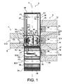
- FIG. 1 an exemplary embodiment of a transfer device 2 according to the present invention can be seen in an open state of the transport packaging.
- the transfer device according to the present invention is intended to be interposed between a transport packaging 4 and a storage device 6.
- the transport packaging 4 comprises a body 8 provided with a cylindrical cavity 10 for receiving a case X10 axis.
- the cylindrical cavity 10 opens on either side of the cylindrical body by a first end (not shown) and a second one. longitudinal end.
- the second end 10.1 is closed by a removable tape 12, and the first end (not shown).
- the storage device 6 comprises a body 11, in which are formed cylindrical housings 14, 16, 18 of axis X14, X16, X16 parallel to each other. Each housing 14, 16, 18 opens on a front face 20 of the storage device 6 and is closed by a tape 24, 26, 28 respectively.
- the storage device with three housings is given by way of example, it may comprise more or less than three housings, which can be distributed vertically and / or horizontally.
- the transfer device 2 comprises a body of longitudinal axis Y intended to be orthogonal to the axes X10, X14, X16, X18.
- the body comprises a sealed envelope 23 formed by walls 26 at the longitudinal ends formed by panels, and lateral flanges 27, 30 front and rear respectively.
- the panels of the walls 26 are, for example welded to ensure a seal at the longitudinal ends.
- the lateral flanges 27, 30, in the example shown comprise removable panels to allow maintenance of the transfer device 2.
- the mounting of the panels is obtained for example by means of O-rings (not shown).
- the envelope 23 defines a sealed cavity 32 in which is slidably mounted a slide 34 along the axis Y.
- the drawer 34 is never in contact with the external environment.
- the drawer 34 has three compartments C1, C2, C3 each comprising a cylindrical passage 25, 27, 29 of axis XC1, XC2, XC3 respectively.
- the axes XC1, XC2, XC3 are parallel to each other and orthogonal to the Y axis.
- the transfer device comprises on each of its lateral faces 27, 30 inflatable seals 35, 37 intended to come into contact with the longitudinal end face of the transport packaging 4.
- Any other means capable of ensuring a seal between the transfer device and the transport packaging and the storage device could be suitable, for example O-rings or flexible sleeves.
- Each seal 35, 37 has for example a circular shape so as to border the periphery of the open end 10.1 of the cavity 10 and the open end of a housing 14, 16, 18. Thus the seals 35, 37 provide a continuous containment.
- the front flanges 27 and rear 30 respectively comprise an opening 31, 33 of diameter allowing the passage of the tapes 12, 24, 26, 28, the openings 31, 33 are aligned along an axis orthogonal to the Y axis.
- C1 compartment comprises means 36 for allowing the removal of the sealing tape 12 of the transport packaging 4 and means 38 to allow the removal of the transport tape 24, 26, 28 housing 14, 16, 18 .
- the withdrawal means 36, 38 are of similar design, only the withdrawal means 36 will be described in detail.
- the withdrawal means 36 comprise a cylinder 40 movable along the axis XC1 and provided with means 42 for hooking onto the tape 12 of the transport packaging 4.
- these attachment means 42 are of the bayonet type or clamp type.
- a free end of the jack 40 comprises at least one pin capable of cooperating with a corresponding pin on an outer face 12.1 of the tape 12 by rotation. The jack 40 moves in the direction indicated by the reference F1 to come dock the tape 12.
- the jack 40 is advantageously a pneumatic cylinder whose compressed air supply is made from a nacelle which will be described later.
- An electrically moved cylinder could also be considered.
- the inside diameter of the passage 25 is at least equal to the outside diameter of the taps 12, 24, 26, 28 to allow storing steps 12, 24, 26, 28 in compartment C1.
- the withdrawal means 38 symmetrically comprise a jack 43, mounted head-to-tail with respect to the jack 40 and operating symmetrically with respect to a plane P orthogonal to the axis XC1.
- the cylinder 43 moves in the direction of the arrow F2 to come dock the tape 24, 26, 28 and moves in the direction F1 to remove it and allow access to the housing 14, 16, 18.
- steps 14, 16, 18 and vice versa no contamination carried by step 12 can be transferred to steps 14, 16, 18 and vice versa.
- the withdrawals of tape 12 and one of the steps of the storage device may be successive or simultaneous.
- the compartment C1 thus allows the removal and storage of the steps of the transport packaging and the storage device and their storage.
- the compartment C2 comprises withdrawal means 50 of a plug 54, 56, 58 mounted in each housing 14, 16, 18 behind the steps 24, 26, 28 to form an additional biological barrier.
- the withdrawal means 50 also comprise a jack 52 movable axially along the axis XC2 and adapted to hook by a free end on the outer face of the plug 54, 56, 58.
- the attachment may be, for example bayonet type or clamp type.
- the inside diameter of the passage 27 of the compartment C2 is substantially equal to the outside diameter of the biological protection plug 54, 56, 58, to allow it to be housed in the compartment C2.
- the compartment C2 thus allows the removal of the biological protection cap 54, 56, 58 from the housing of the storage device and its storage.
- the compartment C3 has an empty cylindrical passage to allow the sliding of the case of the cavity 10 of the transport device to the housing 14, 16, 18 of the storage device.
- the inside diameter of the passage 29 is substantially equal to that of the cavity 10 and the housings 14, 16, 18 in order to achieve a smooth movement of the case, so when the axis X10 of the cavity 10, the axis XC3 of the compartment C3 and the axis X14 or X16 or X18 are aligned, the cavity 10, the passage 29 and the housing 14, 16, 18 form a channel having a substantially continuous cylindrical wall. The risks of shock are therefore reduced.
- the drawer 34 is advantageously moved by an electric motor and a rack system.
- a pneumatic motor can also be envisaged.
- a continuity of the biological barrier is perfectly ensured by forming a sealed passage for the transfer of the case and ensuring the confinement of the biological protection steps and plugs, any transfer with the external environment being avoided .
- the present invention is also intended to check the tightness of the contact between the inflatable seals 35, 37 and the transport packaging and the storage device respectively by means well known to those skilled in the art, such as with pressure rise. Vacuum is made in the area defined by the inflatable seal supposed to be sealed and the pressure is checked. In the event of an increase, the contact is not sealed and maintenance is required.
- the transfer device according to the present invention is, for example intended to be mounted on a nacelle (not shown) on which will be deposited the transport package 4 in contact with the front flange 27 of the transfer device, so as to align the X10 axis of the cavity 10 with the axis of the opening 31 provided in the front flange 27.
- removable connecting means (not shown) between the package 4 and the transfer device 2 are provided to prevent movement between them.
- the nacelle can, for its part, move horizontally and vertically in order to align the axis of the opening made in the rear flange of the transfer device 2 with an axis X 14, X 16, X 18 of a housing 14, 16, 18 respectively of the storage device 6.
- Removable connecting means (not shown) between the storage device and the transfer device are also advantageously provided to prevent movement between them.
- the transfer device 2 is fixed on the storage device 6, during the transfer operations of the case. Moreover, it is supported by the nacelle. For this, the nacelle is moved towards the storage device 6 until the rear flange 30 is arranged parallel to the front face of the storage device 6, so that the inflatable seal 37 comes into contact with the storage device 6. the front of the storage device 6. Before the inflation of the seal 37, the axis of the rear opening 33 is aligned with that of the housing 14.
- the transport packaging loaded with a case is disposed on the platform of the nacelle so as to align the axis X10 of the cavity 10 and the axis of the front opening 31, guide means can be provided for this purpose. effect on the platform of the nacelle.
- the package can be placed on the platform before it reaches the storage device.
- the end face of the transport packaging 4 is placed sufficiently close to the front flange 27 so that the inflatable seal 35 carried by the front flange 27 comes into contact with the end face of the transport packaging 4 and forms a tight zone around the front opening 31.
- the inflation of the seal 35 is performed after the introduction of the transport packaging 4.
- the spool 34 is then moved along the axis Y, so as to align the axis XC1 of the compartment C1 with those of the front openings 31 and rear 33.
- the withdrawal means 36, 38 of the taps are successively or simultaneously operated to remove the taps 12 and 24 as can be seen on the figure 1 .
- the spool 34 is moved up the Y axis until the XC2 axis is aligned with the X14 axes.
- the withdrawal means are then actuated and the biological protection plug is removed and stored in the passage 27, as shown in FIG. figure 2 .
- the drawer 34 is further moved upward to align the XC3 axis with the X10 and X14 axes.
- the case is then moved from the cavity 10 to the housing 14 by sliding, for example by means of a jack coming to apply a thrust force on the case. Traction means could be envisaged passing through the housing 14 and the passage 29 and coming to hang on the case.
- the transfer device is disengaged from the storage device, the nacelle is then released.
- Control means are provided inside the transfer device, these are advantageously visual, for example of the camera type, to check the position of the jacks and the state of withdrawal of the tapes and the biological protection plugs.
- the control of the drawer 34 is performed by an operator who orders the sliding of the drawer 34 after having validated the end of the operation in progress.
- a transfer device having only two compartments, the compartment for removing the tape from the transport packaging and the tape of the housing of the storage device, and the compartment for the transfer of the case is not beyond the scope of the present invention.
- a transfer device in which the removal of the tape 12 and the removal of the tape 24, 26, 28 would take place in two separate compartments also does not fall outside the scope of the present invention.
- a transfer device comprising more than three compartments and / or having compartments providing other functions also does not fall outside the scope of the present invention.
Claims (13)
- Vorrichtung (2) zur Übergabe einer Kernbrennstoffhülle zwischen einer Transportverpackung (4) dieser Hülle und einer Einlagerungsvorrichtung (6) dieser Hülle, wobei die Verpackung (4) einen zylindrischen Hohlraum (10) zur Aufnahme der Hülle und eine Öffnung zum Laden/Entladen der Hülle umfasst, die durch einen Transportverschluss (12) verschlossen ist, wobei die Einlagerungsvorrichtung (6) mindestens eine Aufnahme (14, 16, 18) zur Aufnahme der Hülle und eine Öffnung zum Laden/Entladen der Hülle umfasst, wobei die Öffnung mit einem Lagerverschluss (24, 26, 28) verschlossen ist, wobei diese Übergabevorrichtung (6) einen Körper und einen Schieber (34) mit einer Längsachse aufweist, der geeignet ist, sich entlang seiner Längsachse (Y) im Körper zu verschieben, wobei dieser Schieber (34) mindestens eine erste Abteilung (C1) umfasst, um den Transportverschluss (12) und den Lagerverschluss (24, 26, 28) herauszuziehen, und eine zweite Abteilung (C3), um den Durchgang der Hülle von der Transportverpackung (4) zur Einlagerungsvorrichtung (6) und umgekehrt zu erlauben, und Dichtungsmittel (35, 37), um die Übergabe zwischen der Transportverpackung (4) und der Übergabevorrichtung (2) und zwischen der Übergabevorrichtung (2) und der Einlagerungsvorrichfiung (6) abzudichten.
- Vorrichtung nach Anspruch 1, außerdem umfassend eine Zwischenabteilung (C2) zwischen der ersten (C1) und der zweiten (C3) Abteilung, umfassend einen Durchgang, in welchem Mittel (50) zum Herausziehen einer biologischen Schutzkappe (54, 56, 58) eingebaut sind, die hinter dem Verschluss (24, 26, 28) in der Einlagerungsvorrichtung (6) enthalten ist, wobei diese Kappe (54, 56, 58) in diesem Durchgang gelagert wird.
- Vorrichtung nach Anspruch 1 oder 2, wobei die erste Abteilung (C1) einen axialen Durchgang aufweist, in welchem erste Mittel (36) zum Ausziehen des Transportverschlusses (12) und zweite Mittel (38) zum Ausziehen des Lagerverschlusses (34, 36, 38) eingebaut sind, wobei diese Ausziehmittel (36, 38) vom Typ mit Bajonett oder mit Greifer sind und in diesem Durchgang hin und her beweglich eingebaut sind, wobei
die Verschlüsse (12, 24, 26, 28) beim Herausziehen in diesem Durchgang gelagert werden. - Vorrichtung nach dem vorherigen Anspruch, wobei die ersten Ausziehmittel (36) und die zweiten Ausziehmittel (38) entgegengesetzt tiegeln und in zwei Kammern (46, 48) eingebaut sind, die voneinander isoliert sind.
- Vorrichtung nach einem der Ansprüche 1 bis 4, wobei die zweite Abteilung (C3) einen Durchgang aufweist, dessen Durchmesser größer ist als der der Hülle, um die Übergabe einer Hülle zwischen der Transportverpackung (4) und der Einlagerungsvorrichtung (6) durch diesen Durchgang zu erlauben, wobei dieser Durchmesser im Wesentlichen dem des Hohlraums (10) der Transportverpackung (4) und dem der Aufnahme (14, 16, 18) der Einlagerungsvorrichtung (6) entspricht.
- Vorrichtung nach einem der Ansprüche 1 bis 5, wobei der Körper ein Gehäuse (23) umfasst, das einen dichten Innenraum definiert, in welchem der Schieber (34) sich verschieben kann, wobei dieses Gehäuse (23) Seitenwände (27, 30) aufweist, die jeweils mit einer Öffnung (31) versehen sind, die dazu bestimmt ist, dem Hohlraum (10) der Transportverpackung (4) gegenüberzuliegen, und mit einer Öffnung (33), die dazu bestimmt ist, der Aufnahme (14, 16, 18) der Einlagerungsvorrichtung (6) gegenüberzuliegen, und die Mittel (35, 37) zur Abdichtung der Übergabe eine erste (35) und eine zweite (37) aufblasbare Dichtung umfassen, die mit den Seitenwänden (27, 30) fest verbunden sind, jede der Öffnungen (31, 33) auf durchgehende Weise umgeben und dazu bestimmt sind, jeweils mit einer Endseite der Transportverpackung (4) und mit einer Endseite der Einlagerungvorrichtung (6) in Kontakt zu kommen.
- Vorrichtung nach dem vorherigen Anspruch, wobei die Seitenwände (27, 30) abnehmbare Platten (27.1, 30.1) aufweisen, die die Wartung erlauben, wobei diese Platten (27.1, 30.1), wobei diese Platten (27.1, 30.1) auf dichte Weise montiert sind, um die Dichtigkeit des Gehäuses zu gewährleisten.
- Vorrichtung nach einem der Ansprüche 1 bis 7, wobei der Schieber (34) mithilfe eines Elektromotors verschoben wird.
- Vorrichtung nach Anspruch 3, wobei die Ausziehmittel (36, 38, 50) durch Druckluft betätigt werden.
- Verfahren zur Übergabe einer Kernbrennstoffhülle zwischen einer Transportverpackung und einer Einlagerungsvorrichtung mithilfe einer Übergabevorrichtung, umfassend einen Schieber, der mindestens mit einer ersten Abteilung zum Herausziehen der Verschlüsse der Transportverpackung und der Einlagerungsvorrichtung, einer zweiten Abteilung für den Durchgang der Hülle und Dichtungsmittein zwischen der Übergabevorrichtung und der Transportverpackung und der Einlagerungsvorrichtung versehen ist, wobei das Verfahren die folgenden Schritte umfasst:a) das Ausrichten der Übergabevorrichtung mit der Transportverpackung und der Einlagerurgsvarrichtung,b) das Ausrichten der ersten Abteilung des Schiebers mit dem Hohlraum der Transportverpackung und einer Aufnahme der Einlagerungsvorrichtung durch Bewegen des Schiebers,c) das Herausziehen des Transportverschlusses und des Lagerverschlusses,d) das Ausrichten der zweiten Abteilung mit dem Hohlraum der Transportverpackung und der Aufnahme der Einlagerungsvorrichtung durch Bewegen des Schiebers,e) das Verschieben der Hülle zwischen der Einlagerungsvorrichtung und der Transportverpackung.
- Übergabeverfahren nach Anspruch 10, umfassend einen Schritt c') des Ausrichtens einer Zwischenabteilung mit dem Hohlraum der Transportverpackung und der Aufnahme der Einlagerungsvorrichtung durch Bewegen des Schiebers, und einen Schritt c") des Herausziehens einer Kappe, die hinter dem Lagerverschluss in der Aufnahme enthalten ist.
- Übergabeverfahren nach Anspruch 10 oder 11, umfassend, nach Schritt a), den Schritt des Aufblasens der Dichtungen, die von der Vorrichtung getragen werden und mit der Transportverpackung und der Einlagerungsvorrichtung in Kontakt sind, um einen dichten Kontakt zwischen der Übergabevorrichtung und der Transportverpackung und der Einlagerungsvorrichtung zu gewährleisten.
- Übergabeverfahren nach einem der Ansprüche 10 bis 12, wobei in Schritt a) eine Kopplung der Übergabevorrichtung an die Einlagerungsvorrichtung und an die Transportverpackung vorgesehen ist.
Applications Claiming Priority (2)
| Application Number | Priority Date | Filing Date | Title |
|---|---|---|---|
| FR0655295A FR2909480B1 (fr) | 2006-12-04 | 2006-12-04 | Dispositif de transfert d'etuis de combustible nucleaire entre un emballage de transport et un dispositif d'entreposage |
| PCT/EP2007/063040 WO2008068190A1 (fr) | 2006-12-04 | 2007-11-30 | Dispositif de transfert d'etuis de combustible nucleaire entre un emballage de transport et un dispositif d'entreposage |
Publications (2)
| Publication Number | Publication Date |
|---|---|
| EP2100309A1 EP2100309A1 (de) | 2009-09-16 |
| EP2100309B1 true EP2100309B1 (de) | 2011-04-06 |
Family
ID=38236436
Family Applications (1)
| Application Number | Title | Priority Date | Filing Date |
|---|---|---|---|
| EP07847556A Not-in-force EP2100309B1 (de) | 2006-12-04 | 2007-11-30 | Einrichtung zum transfer von kernbrennstoffkassetten zwischen einem transportbehälter und einer lagereinrichtung |
Country Status (7)
| Country | Link |
|---|---|
| US (1) | US8792606B2 (de) |
| EP (1) | EP2100309B1 (de) |
| JP (1) | JP5658877B2 (de) |
| AT (1) | ATE504924T1 (de) |
| DE (1) | DE602007013804D1 (de) |
| FR (1) | FR2909480B1 (de) |
| WO (1) | WO2008068190A1 (de) |
Families Citing this family (6)
| Publication number | Priority date | Publication date | Assignee | Title |
|---|---|---|---|---|
| US20110243293A1 (en) * | 2010-03-31 | 2011-10-06 | Peter Ray Diller | Systems and Methods for Servicing a Fuel Assembly in a Light Water Reactor |
| WO2012068547A2 (en) * | 2010-11-19 | 2012-05-24 | Transnuclear, Inc. | Systems methods, and components for transferring radioactive material |
| US10648823B2 (en) | 2017-06-22 | 2020-05-12 | Aeris Communications, Inc. | Learning common routes and automatic geofencing in fleet management |
| JP2017162956A (ja) * | 2016-03-09 | 2017-09-14 | 株式会社村田製作所 | 電子部品及びその製造方法 |
| CN108986945A (zh) * | 2018-06-11 | 2018-12-11 | 中国核电工程有限公司 | 一种放射性物料转运装置 |
| FR3084509B1 (fr) * | 2018-07-24 | 2021-01-08 | Commissariat Energie Atomique | Dispositif de manutention pour assemblage combustible et ensemble de manutention comprenant un tel dispositif |
Family Cites Families (10)
| Publication number | Priority date | Publication date | Assignee | Title |
|---|---|---|---|---|
| FR1395783A (fr) * | 1964-03-05 | 1965-04-16 | Commissariat Energie Atomique | Dispositif de liaison étanche |
| JPS60171493A (ja) * | 1984-02-17 | 1985-09-04 | 日立造船株式会社 | 燃料輸送容器への核燃料収納方法と燃料輸送容器用プラグ |
| US4780269A (en) * | 1985-03-12 | 1988-10-25 | Nutech, Inc. | Horizontal modular dry irradiated fuel storage system |
| DE3717189C1 (de) * | 1987-05-22 | 1988-11-10 | Nuklear Service Gmbh Gns | Vorrichtung fuer die UEbergabe eines radioaktiven Gegenstandes aus einem Erstbehaelter in einen Zweitbehaelter |
| GB9808175D0 (en) * | 1998-04-17 | 1998-06-17 | Coles Timothy P | Rotary gas sanitiser |
| JP2002148387A (ja) * | 2000-11-07 | 2002-05-22 | Mitsubishi Heavy Ind Ltd | 貯蔵容器、貯蔵容器の詰替えシステム、および詰替え方法 |
| RU2192677C1 (ru) * | 2001-09-26 | 2002-11-10 | Открытое акционерное общество "ЭМК-Атоммаш" | Транспортный шлюз |
| US6625246B1 (en) * | 2002-04-12 | 2003-09-23 | Holtec International, Inc. | System and method for transferring spent nuclear fuel from a spent nuclear fuel pool to a storage cask |
| JP3970162B2 (ja) * | 2002-11-11 | 2007-09-05 | 三菱重工業株式会社 | 地層処分時の高レベル廃棄物定置装置 |
| JP4285100B2 (ja) * | 2003-06-20 | 2009-06-24 | 株式会社Ihi | 原子炉使用済燃料の水平装荷用詰替設備 |
-
2006
- 2006-12-04 FR FR0655295A patent/FR2909480B1/fr not_active Expired - Fee Related
-
2007
- 2007-11-30 DE DE602007013804T patent/DE602007013804D1/de active Active
- 2007-11-30 AT AT07847556T patent/ATE504924T1/de not_active IP Right Cessation
- 2007-11-30 US US12/516,186 patent/US8792606B2/en not_active Expired - Fee Related
- 2007-11-30 EP EP07847556A patent/EP2100309B1/de not_active Not-in-force
- 2007-11-30 JP JP2009538719A patent/JP5658877B2/ja not_active Expired - Fee Related
- 2007-11-30 WO PCT/EP2007/063040 patent/WO2008068190A1/fr active Application Filing
Also Published As
| Publication number | Publication date |
|---|---|
| EP2100309A1 (de) | 2009-09-16 |
| US8792606B2 (en) | 2014-07-29 |
| FR2909480A1 (fr) | 2008-06-06 |
| WO2008068190A1 (fr) | 2008-06-12 |
| JP5658877B2 (ja) | 2015-01-28 |
| JP2010511855A (ja) | 2010-04-15 |
| FR2909480B1 (fr) | 2009-02-20 |
| US20100027730A1 (en) | 2010-02-04 |
| DE602007013804D1 (de) | 2011-05-19 |
| ATE504924T1 (de) | 2011-04-15 |
Similar Documents
| Publication | Publication Date | Title |
|---|---|---|
| EP2100309B1 (de) | Einrichtung zum transfer von kernbrennstoffkassetten zwischen einem transportbehälter und einer lagereinrichtung | |
| EP2011124B1 (de) | Ladebehälter-fass für mindestens ein kernbrennstoffbündel und ladeprozedur | |
| EP0123598B1 (de) | Drehbarer Transport- und Ersatzbehälter für verunreinigte Teile und Ergänzungsetui für diesen Behälter | |
| EP1463614B1 (de) | Verfahren zum anschliessen einer handhabungseinrichtung an eine hülle mit sterilem inhalt | |
| EP2617040B1 (de) | Vorrichtung zur trockenhandhabung von kernbrennstabbündeln | |
| EP2082403A1 (de) | Lagerbehälter für radioaktiven abfall | |
| EP2092533B1 (de) | Kernbrennstoff-transporteinrichtung und verfahren zum beladen/entladen der einrichtung | |
| EP3042378B1 (de) | Verpackung mit verbesserten mitteln zur stossdämpfung zwischen einer anordnung mit radioaktiven materialien und deckel für diese verpackung | |
| WO2005034217A9 (fr) | Procede et dispositif de conditionnement de crayons de combustible nucleaire non etanches en vue de leur transport et de leur stockage ou entreposage de longue duree | |
| WO2007085586A2 (fr) | Procede et dispositif de fermeture en piscine d'un etui charge avec du combustible nucleaire irradie | |
| EP2419908B1 (de) | Einschlussvorrichtung zum transport und zur end- und zwischenlagerung von radioaktiven stoffen | |
| EP3691787B1 (de) | Vorrichtung mit dichter verbindung zum aseptischen transfer eines biopharmazeutischen produkts zwischen einer kammer und einem behälter | |
| EP2789550B1 (de) | Handhabungs- und Begrenzungshaube, Anwendung zur Handhabung von Probengefäßen für nukleares Material, insbesondere Kernbrennstoffe | |
| EP1946330B1 (de) | Brennstoffmantelungs-schutzkragen, verfahren zum herstellen von brennstoffstäben und einrichtung zum ausführen des verfahrens | |
| WO2020193540A1 (fr) | Station de recharge pour drone | |
| EP2872300B1 (de) | Vorrichtung zur handhabung von behältern mit gegenständen | |
| EP4126692B1 (de) | Verschluss geeignet um eine flüssigkeit zu enthalten | |
| Delfosse | Container for radioactive gas |
Legal Events
| Date | Code | Title | Description |
|---|---|---|---|
| PUAI | Public reference made under article 153(3) epc to a published international application that has entered the european phase |
Free format text: ORIGINAL CODE: 0009012 |
|
| 17P | Request for examination filed |
Effective date: 20090602 |
|
| AK | Designated contracting states |
Kind code of ref document: A1 Designated state(s): AT BE BG CH CY CZ DE DK EE ES FI FR GB GR HU IE IS IT LI LT LU LV MC MT NL PL PT RO SE SI SK TR |
|
| DAX | Request for extension of the european patent (deleted) | ||
| RAP1 | Party data changed (applicant data changed or rights of an application transferred) |
Owner name: COMMISSARIAT A L'ENERGIE ATOMIQUE ET AUX ENERGIES |
|
| GRAP | Despatch of communication of intention to grant a patent |
Free format text: ORIGINAL CODE: EPIDOSNIGR1 |
|
| GRAS | Grant fee paid |
Free format text: ORIGINAL CODE: EPIDOSNIGR3 |
|
| GRAA | (expected) grant |
Free format text: ORIGINAL CODE: 0009210 |
|
| AK | Designated contracting states |
Kind code of ref document: B1 Designated state(s): AT BE BG CH CY CZ DE DK EE ES FI FR GB GR HU IE IS IT LI LT LU LV MC MT NL PL PT RO SE SI SK TR |
|
| REG | Reference to a national code |
Ref country code: GB Ref legal event code: FG4D Free format text: NOT ENGLISH |
|
| REG | Reference to a national code |
Ref country code: CH Ref legal event code: EP |
|
| REG | Reference to a national code |
Ref country code: IE Ref legal event code: FG4D |
|
| REF | Corresponds to: |
Ref document number: 602007013804 Country of ref document: DE Date of ref document: 20110519 Kind code of ref document: P |
|
| REG | Reference to a national code |
Ref country code: DE Ref legal event code: R096 Ref document number: 602007013804 Country of ref document: DE Effective date: 20110519 |
|
| REG | Reference to a national code |
Ref country code: NL Ref legal event code: VDEP Effective date: 20110406 |
|
| PG25 | Lapsed in a contracting state [announced via postgrant information from national office to epo] |
Ref country code: SI Free format text: LAPSE BECAUSE OF FAILURE TO SUBMIT A TRANSLATION OF THE DESCRIPTION OR TO PAY THE FEE WITHIN THE PRESCRIBED TIME-LIMIT Effective date: 20110406 |
|
| LTIE | Lt: invalidation of european patent or patent extension |
Effective date: 20110406 |
|
| REG | Reference to a national code |
Ref country code: IE Ref legal event code: FD4D |
|
| PG25 | Lapsed in a contracting state [announced via postgrant information from national office to epo] |
Ref country code: LT Free format text: LAPSE BECAUSE OF FAILURE TO SUBMIT A TRANSLATION OF THE DESCRIPTION OR TO PAY THE FEE WITHIN THE PRESCRIBED TIME-LIMIT Effective date: 20110406 Ref country code: SE Free format text: LAPSE BECAUSE OF FAILURE TO SUBMIT A TRANSLATION OF THE DESCRIPTION OR TO PAY THE FEE WITHIN THE PRESCRIBED TIME-LIMIT Effective date: 20110406 Ref country code: PT Free format text: LAPSE BECAUSE OF FAILURE TO SUBMIT A TRANSLATION OF THE DESCRIPTION OR TO PAY THE FEE WITHIN THE PRESCRIBED TIME-LIMIT Effective date: 20110808 |
|
| PG25 | Lapsed in a contracting state [announced via postgrant information from national office to epo] |
Ref country code: AT Free format text: LAPSE BECAUSE OF FAILURE TO SUBMIT A TRANSLATION OF THE DESCRIPTION OR TO PAY THE FEE WITHIN THE PRESCRIBED TIME-LIMIT Effective date: 20110406 Ref country code: CY Free format text: LAPSE BECAUSE OF FAILURE TO SUBMIT A TRANSLATION OF THE DESCRIPTION OR TO PAY THE FEE WITHIN THE PRESCRIBED TIME-LIMIT Effective date: 20110406 Ref country code: ES Free format text: LAPSE BECAUSE OF FAILURE TO SUBMIT A TRANSLATION OF THE DESCRIPTION OR TO PAY THE FEE WITHIN THE PRESCRIBED TIME-LIMIT Effective date: 20110717 Ref country code: FI Free format text: LAPSE BECAUSE OF FAILURE TO SUBMIT A TRANSLATION OF THE DESCRIPTION OR TO PAY THE FEE WITHIN THE PRESCRIBED TIME-LIMIT Effective date: 20110406 Ref country code: LV Free format text: LAPSE BECAUSE OF FAILURE TO SUBMIT A TRANSLATION OF THE DESCRIPTION OR TO PAY THE FEE WITHIN THE PRESCRIBED TIME-LIMIT Effective date: 20110406 Ref country code: IS Free format text: LAPSE BECAUSE OF FAILURE TO SUBMIT A TRANSLATION OF THE DESCRIPTION OR TO PAY THE FEE WITHIN THE PRESCRIBED TIME-LIMIT Effective date: 20110806 Ref country code: GR Free format text: LAPSE BECAUSE OF FAILURE TO SUBMIT A TRANSLATION OF THE DESCRIPTION OR TO PAY THE FEE WITHIN THE PRESCRIBED TIME-LIMIT Effective date: 20110707 |
|
| PG25 | Lapsed in a contracting state [announced via postgrant information from national office to epo] |
Ref country code: NL Free format text: LAPSE BECAUSE OF FAILURE TO SUBMIT A TRANSLATION OF THE DESCRIPTION OR TO PAY THE FEE WITHIN THE PRESCRIBED TIME-LIMIT Effective date: 20110406 |
|
| PG25 | Lapsed in a contracting state [announced via postgrant information from national office to epo] |
Ref country code: CZ Free format text: LAPSE BECAUSE OF FAILURE TO SUBMIT A TRANSLATION OF THE DESCRIPTION OR TO PAY THE FEE WITHIN THE PRESCRIBED TIME-LIMIT Effective date: 20110406 Ref country code: IE Free format text: LAPSE BECAUSE OF FAILURE TO SUBMIT A TRANSLATION OF THE DESCRIPTION OR TO PAY THE FEE WITHIN THE PRESCRIBED TIME-LIMIT Effective date: 20110406 Ref country code: EE Free format text: LAPSE BECAUSE OF FAILURE TO SUBMIT A TRANSLATION OF THE DESCRIPTION OR TO PAY THE FEE WITHIN THE PRESCRIBED TIME-LIMIT Effective date: 20110406 |
|
| PLBE | No opposition filed within time limit |
Free format text: ORIGINAL CODE: 0009261 |
|
| STAA | Information on the status of an ep patent application or granted ep patent |
Free format text: STATUS: NO OPPOSITION FILED WITHIN TIME LIMIT |
|
| PG25 | Lapsed in a contracting state [announced via postgrant information from national office to epo] |
Ref country code: RO Free format text: LAPSE BECAUSE OF FAILURE TO SUBMIT A TRANSLATION OF THE DESCRIPTION OR TO PAY THE FEE WITHIN THE PRESCRIBED TIME-LIMIT Effective date: 20110406 Ref country code: DK Free format text: LAPSE BECAUSE OF FAILURE TO SUBMIT A TRANSLATION OF THE DESCRIPTION OR TO PAY THE FEE WITHIN THE PRESCRIBED TIME-LIMIT Effective date: 20110406 Ref country code: SK Free format text: LAPSE BECAUSE OF FAILURE TO SUBMIT A TRANSLATION OF THE DESCRIPTION OR TO PAY THE FEE WITHIN THE PRESCRIBED TIME-LIMIT Effective date: 20110406 Ref country code: PL Free format text: LAPSE BECAUSE OF FAILURE TO SUBMIT A TRANSLATION OF THE DESCRIPTION OR TO PAY THE FEE WITHIN THE PRESCRIBED TIME-LIMIT Effective date: 20110406 |
|
| 26N | No opposition filed |
Effective date: 20120110 |
|
| REG | Reference to a national code |
Ref country code: DE Ref legal event code: R097 Ref document number: 602007013804 Country of ref document: DE Effective date: 20120110 |
|
| BERE | Be: lapsed |
Owner name: COMMISSARIAT A L'ENERGIE ATOMIQUE ET AUX ENERGIES Effective date: 20111130 |
|
| PG25 | Lapsed in a contracting state [announced via postgrant information from national office to epo] |
Ref country code: MC Free format text: LAPSE BECAUSE OF NON-PAYMENT OF DUE FEES Effective date: 20111130 |
|
| PG25 | Lapsed in a contracting state [announced via postgrant information from national office to epo] |
Ref country code: BE Free format text: LAPSE BECAUSE OF NON-PAYMENT OF DUE FEES Effective date: 20111130 |
|
| PG25 | Lapsed in a contracting state [announced via postgrant information from national office to epo] |
Ref country code: MT Free format text: LAPSE BECAUSE OF FAILURE TO SUBMIT A TRANSLATION OF THE DESCRIPTION OR TO PAY THE FEE WITHIN THE PRESCRIBED TIME-LIMIT Effective date: 20110406 |
|
| PG25 | Lapsed in a contracting state [announced via postgrant information from national office to epo] |
Ref country code: LU Free format text: LAPSE BECAUSE OF NON-PAYMENT OF DUE FEES Effective date: 20111130 |
|
| PG25 | Lapsed in a contracting state [announced via postgrant information from national office to epo] |
Ref country code: BG Free format text: LAPSE BECAUSE OF FAILURE TO SUBMIT A TRANSLATION OF THE DESCRIPTION OR TO PAY THE FEE WITHIN THE PRESCRIBED TIME-LIMIT Effective date: 20110706 |
|
| PG25 | Lapsed in a contracting state [announced via postgrant information from national office to epo] |
Ref country code: TR Free format text: LAPSE BECAUSE OF FAILURE TO SUBMIT A TRANSLATION OF THE DESCRIPTION OR TO PAY THE FEE WITHIN THE PRESCRIBED TIME-LIMIT Effective date: 20110406 |
|
| PG25 | Lapsed in a contracting state [announced via postgrant information from national office to epo] |
Ref country code: HU Free format text: LAPSE BECAUSE OF FAILURE TO SUBMIT A TRANSLATION OF THE DESCRIPTION OR TO PAY THE FEE WITHIN THE PRESCRIBED TIME-LIMIT Effective date: 20110406 |
|
| PG25 | Lapsed in a contracting state [announced via postgrant information from national office to epo] |
Ref country code: IT Free format text: LAPSE BECAUSE OF FAILURE TO SUBMIT A TRANSLATION OF THE DESCRIPTION OR TO PAY THE FEE WITHIN THE PRESCRIBED TIME-LIMIT Effective date: 20110406 |
|
| REG | Reference to a national code |
Ref country code: FR Ref legal event code: PLFP Year of fee payment: 9 |
|
| REG | Reference to a national code |
Ref country code: FR Ref legal event code: PLFP Year of fee payment: 10 |
|
| REG | Reference to a national code |
Ref country code: FR Ref legal event code: PLFP Year of fee payment: 11 |
|
| PGFP | Annual fee paid to national office [announced via postgrant information from national office to epo] |
Ref country code: DE Payment date: 20181112 Year of fee payment: 12 |
|
| PGFP | Annual fee paid to national office [announced via postgrant information from national office to epo] |
Ref country code: GB Payment date: 20181116 Year of fee payment: 12 Ref country code: FR Payment date: 20181129 Year of fee payment: 12 Ref country code: CH Payment date: 20181120 Year of fee payment: 12 |
|
| REG | Reference to a national code |
Ref country code: DE Ref legal event code: R119 Ref document number: 602007013804 Country of ref document: DE |
|
| REG | Reference to a national code |
Ref country code: CH Ref legal event code: PL |
|
| PG25 | Lapsed in a contracting state [announced via postgrant information from national office to epo] |
Ref country code: LI Free format text: LAPSE BECAUSE OF NON-PAYMENT OF DUE FEES Effective date: 20191130 Ref country code: CH Free format text: LAPSE BECAUSE OF NON-PAYMENT OF DUE FEES Effective date: 20191130 |
|
| GBPC | Gb: european patent ceased through non-payment of renewal fee |
Effective date: 20191130 |
|
| PG25 | Lapsed in a contracting state [announced via postgrant information from national office to epo] |
Ref country code: DE Free format text: LAPSE BECAUSE OF NON-PAYMENT OF DUE FEES Effective date: 20200603 Ref country code: GB Free format text: LAPSE BECAUSE OF NON-PAYMENT OF DUE FEES Effective date: 20191130 Ref country code: FR Free format text: LAPSE BECAUSE OF NON-PAYMENT OF DUE FEES Effective date: 20191130 |