EP2872300B1 - Vorrichtung zur handhabung von behältern mit gegenständen - Google Patents
Vorrichtung zur handhabung von behältern mit gegenständen Download PDFInfo
- Publication number
- EP2872300B1 EP2872300B1 EP13735292.8A EP13735292A EP2872300B1 EP 2872300 B1 EP2872300 B1 EP 2872300B1 EP 13735292 A EP13735292 A EP 13735292A EP 2872300 B1 EP2872300 B1 EP 2872300B1
- Authority
- EP
- European Patent Office
- Prior art keywords
- jaws
- case
- stop
- housing
- opening
- Prior art date
- Legal status (The legal status is an assumption and is not a legal conclusion. Google has not performed a legal analysis and makes no representation as to the accuracy of the status listed.)
- Active
Links
- 238000009434 installation Methods 0.000 claims description 17
- 238000000605 extraction Methods 0.000 claims description 11
- SHZGCJCMOBCMKK-KGJVWPDLSA-N beta-L-fucose Chemical compound C[C@@H]1O[C@H](O)[C@@H](O)[C@H](O)[C@@H]1O SHZGCJCMOBCMKK-KGJVWPDLSA-N 0.000 claims description 9
- 238000005520 cutting process Methods 0.000 claims description 9
- 230000005484 gravity Effects 0.000 claims description 9
- 230000033001 locomotion Effects 0.000 claims description 9
- 238000006073 displacement reaction Methods 0.000 claims description 5
- 230000005540 biological transmission Effects 0.000 claims description 4
- 238000001514 detection method Methods 0.000 claims description 3
- 238000013519 translation Methods 0.000 claims description 3
- 238000011084 recovery Methods 0.000 description 13
- 238000004519 manufacturing process Methods 0.000 description 9
- 239000003758 nuclear fuel Substances 0.000 description 5
- 239000000446 fuel Substances 0.000 description 4
- 239000000463 material Substances 0.000 description 3
- 238000012958 reprocessing Methods 0.000 description 3
- 239000002915 spent fuel radioactive waste Substances 0.000 description 2
- 238000003860 storage Methods 0.000 description 2
- 238000012546 transfer Methods 0.000 description 2
- 238000005303 weighing Methods 0.000 description 2
- 229910052778 Plutonium Inorganic materials 0.000 description 1
- 230000007547 defect Effects 0.000 description 1
- 238000013461 design Methods 0.000 description 1
- 230000006866 deterioration Effects 0.000 description 1
- 238000003780 insertion Methods 0.000 description 1
- 230000037431 insertion Effects 0.000 description 1
- 238000012423 maintenance Methods 0.000 description 1
- 238000005259 measurement Methods 0.000 description 1
- 229910052751 metal Inorganic materials 0.000 description 1
- 239000002184 metal Substances 0.000 description 1
- 230000035515 penetration Effects 0.000 description 1
- OYEHPCDNVJXUIW-UHFFFAOYSA-N plutonium atom Chemical compound [Pu] OYEHPCDNVJXUIW-UHFFFAOYSA-N 0.000 description 1
- 238000005096 rolling process Methods 0.000 description 1
- 230000035939 shock Effects 0.000 description 1
- 238000004513 sizing Methods 0.000 description 1
- 230000001360 synchronised effect Effects 0.000 description 1
Images


Classifications
-
- B—PERFORMING OPERATIONS; TRANSPORTING
- B25—HAND TOOLS; PORTABLE POWER-DRIVEN TOOLS; MANIPULATORS
- B25J—MANIPULATORS; CHAMBERS PROVIDED WITH MANIPULATION DEVICES
- B25J15/00—Gripping heads and other end effectors
- B25J15/0028—Gripping heads and other end effectors with movable, e.g. pivoting gripping jaw surfaces
-
- B—PERFORMING OPERATIONS; TRANSPORTING
- B25—HAND TOOLS; PORTABLE POWER-DRIVEN TOOLS; MANIPULATORS
- B25J—MANIPULATORS; CHAMBERS PROVIDED WITH MANIPULATION DEVICES
- B25J11/00—Manipulators not otherwise provided for
-
- B—PERFORMING OPERATIONS; TRANSPORTING
- B65—CONVEYING; PACKING; STORING; HANDLING THIN OR FILAMENTARY MATERIAL
- B65G—TRANSPORT OR STORAGE DEVICES, e.g. CONVEYORS FOR LOADING OR TIPPING, SHOP CONVEYOR SYSTEMS OR PNEUMATIC TUBE CONVEYORS
- B65G65/00—Loading or unloading
- B65G65/30—Methods or devices for filling or emptying bunkers, hoppers, tanks, or like containers, of interest apart from their use in particular chemical or physical processes or their application in particular machines, e.g. not covered by a single other subclass
- B65G65/34—Emptying devices
- B65G65/36—Devices for emptying from the top
- B65G65/38—Mechanical devices
-
- G—PHYSICS
- G21—NUCLEAR PHYSICS; NUCLEAR ENGINEERING
- G21F—PROTECTION AGAINST X-RADIATION, GAMMA RADIATION, CORPUSCULAR RADIATION OR PARTICLE BOMBARDMENT; TREATING RADIOACTIVELY CONTAMINATED MATERIAL; DECONTAMINATION ARRANGEMENTS THEREFOR
- G21F7/00—Shielded cells or rooms
- G21F7/04—Shielded glove-boxes
-
- G—PHYSICS
- G21—NUCLEAR PHYSICS; NUCLEAR ENGINEERING
- G21F—PROTECTION AGAINST X-RADIATION, GAMMA RADIATION, CORPUSCULAR RADIATION OR PARTICLE BOMBARDMENT; TREATING RADIOACTIVELY CONTAMINATED MATERIAL; DECONTAMINATION ARRANGEMENTS THEREFOR
- G21F7/00—Shielded cells or rooms
- G21F7/06—Structural combination with remotely-controlled apparatus, e.g. with manipulators
-
- B—PERFORMING OPERATIONS; TRANSPORTING
- B25—HAND TOOLS; PORTABLE POWER-DRIVEN TOOLS; MANIPULATORS
- B25J—MANIPULATORS; CHAMBERS PROVIDED WITH MANIPULATION DEVICES
- B25J15/00—Gripping heads and other end effectors
-
- B—PERFORMING OPERATIONS; TRANSPORTING
- B65—CONVEYING; PACKING; STORING; HANDLING THIN OR FILAMENTARY MATERIAL
- B65B—MACHINES, APPARATUS OR DEVICES FOR, OR METHODS OF, PACKAGING ARTICLES OR MATERIALS; UNPACKING
- B65B69/00—Unpacking of articles or materials, not otherwise provided for
- B65B69/0033—Unpacking of articles or materials, not otherwise provided for by cutting
-
- G—PHYSICS
- G21—NUCLEAR PHYSICS; NUCLEAR ENGINEERING
- G21F—PROTECTION AGAINST X-RADIATION, GAMMA RADIATION, CORPUSCULAR RADIATION OR PARTICLE BOMBARDMENT; TREATING RADIOACTIVELY CONTAMINATED MATERIAL; DECONTAMINATION ARRANGEMENTS THEREFOR
- G21F7/00—Shielded cells or rooms
- G21F7/06—Structural combination with remotely-controlled apparatus, e.g. with manipulators
- G21F7/061—Integrated manipulators
Definitions
- the present invention relates to a case handling device containing objects; for example, it may be cases containing boxes filled with materials for the manufacture of nuclear fuel.
- Such a device is for example presented in the document FR 2964091 .
- the plutonium oxide is recovered after reprocessing the spent fuel, and is stored in tightly sealed metal cans, these boxes being stacked in an equally metallic case and closed in a closed manner. waterproof. These cases are then transported from spent fuel reprocessing plants to MOX fuel fabrication plants.
- the opening of the case and the handling of the plutonium boxes are done in a glove box using robots that can be controlled from outside the glove box. Therefore, the device or devices handling the cases and boxes must be robust and reliable to reduce the number of incidents and avoid maintenance that are complex and usually very long to achieve in a glove box. In addition, the boxes must be handled with care to prevent damage, which could cause leakage of the material they contain or interfere with their handling in the rest of the installation, for example for opening and / or storage.
- a handling device comprising a housing for receiving the case, this housing being closed at one end and having at the other end means for holding the case, these means comprising two jaws for to tighten the case, these means also comprising two jaws forming a stop for the boxes contained in the case when the case is open.
- These jaws are mounted free on the clamping jaws of the case and are biased towards each other by elastic means so that, when the jaws are opened, the stop jaws are also open and such that the stop jaws can be opened independently of the clamping jaws.
- these stop jaws cooperate with a box recovery device when they are removed from the case, this recovery device comprising fingers intended to cooperate with the stop jaws to remove them and allow the passage of boxes while the case is held tight by the clamping jaws.
- the boxes are then extracted from the case and received by the recovery device.
- the evacuation of the boxes is done by gravity.
- the housing is made in a wheel that is rotatable about its axis, the housing extending along a diameter of the wheel, the rotation of the wheel allowing the case to reach different stations where it undergoes different operations.
- the present invention therefore relates to a device for handling cases and boxes contained in the cases, the cases being of cylindrical shape, said device comprising a housing with a longitudinal axis for receiving a case, said housing being closed at a first longitudinal end and open at a second longitudinal end, a holding device mounted at the second end of the housing, said holding device comprising two clamping jaws adapted to be displaced about an axis orthogonal to the longitudinal axis of the housing, said clamping jaws being intended to apply a clamping force on the case so as to hold it longitudinally in the housing, at least an actuator for opening and closing said clamping jaws, two stop jaws, each being carried by a clamping jaw and being freely articulated about the axis of rotation of the clamping jaw, said stop jaws being biased against the to one another in the abutment position by resilient means, so that the opening of the The clamping jaws cause the stopper jaws to open and in such a way that the stopper jaws can be opened independently of the clamping jaws.
- the device may comprise a wheel rotatable about its axis, said housing being formed in said wheel and extending along a diameter of said wheel.
- One of the clamping jaws may include a shoulder forming a longitudinal stop for the case.
- the other clamping jaw may comprise a face inclined relative to the axis of the housing towards the outside of the housing.
- At least one of the stop jaws comprises a free rotating roller bordering the passage defined by the two stop jaws so as to facilitate the exit of the object contained in the case.
- each stopper jaw has opening faces on either side of the passage defined by the two stop jaws, said opening faces of a stopper jaw being opposite faces of the stopper jaws. opening of the other abutment jaw, said opening faces being intended to cooperate each with ramps carried by an opening device.
- the opening faces each comprise a freely rotating roller cooperating with one of said ramps.
- the handling device comprises at least one sensor for measuring the position of the stop jaws.
- the device comprises a single sensor measuring the relative position of the stop jaws, said sensor being carried by an integral arm in motion of one of the jaws and being sensitive to the movement of another integral arm in motion of the other stop jaw.
- the device may include an actuator for rotatably moving one of the clamping jaws and transmission means to transmit movement to the other clamping jaw so as to cause the clamping jaws to move away from or toward each other.
- the clamping jaws comprise two lateral flanges articulated on a frame of the handling device, and in which the transmission means are formed by teeth carried by each lateral flange, said lateral flanges having teeth meshing so that rotation in one direction of one of the clamping jaws causes rotation in a direction opposite to the other clamping jaw.
- the resilient means recalling the stop jaws may comprise two helical springs disposed on either side of the longitudinal axis of the housing, each coil spring being fixed by one end to a stop jaw and from one end to the other. jaw of stop.
- the device comprises means for adjusting the tension of the springs.
- the handling device may include a device for moving the case along the longitudinal axis of the housing disposed in the housing.
- the present invention also relates to a handling facility of a case and boxes contained in the case comprising a handling device according to the invention, a case opening device for separating a case head from a case body and make accessible the objects contained in the case, and a device for extracting and recovering objects contained in the cases.
- the device for opening cases and the device for extracting and retrieving the objects contained in the cases are arranged around a wheel.
- the case opening device is a cutting device disposed above the wheel and the extraction and recovery device is disposed below the wheel so that the extraction of the objects of the body of the holster is obtained by gravity.
- the longitudinal axis of the housing is preferably oriented at an angle of 45 ° relative to a horizontal direction.
- the extraction and recovery device may comprise an arm of longitudinal axis displaceable at least in rotation about an axis parallel to the axis of the wheel, a carriage mounted to be movable in translation on the arm along the axis. longitudinal axis of the arm, a housing carried by the carriage for receiving an object contained in the case, and means for opening the stopper jaws.
- the means for opening the stop jaws comprise, for example, four fingers carried by the carriage and bordering the housing, said fingers being oriented parallel to the longitudinal axis of the arm and each being provided at a free end with a ramp designed to cooperate with each other. with the stopper jaws so that when the fingers are inserted between the stopper jaws, they move away from each other.
- the carriage comprises means for detecting the presence of the object.
- the installation may include a device for recovering the empty case, arranged under the wheel so that the evacuation of the empty case body is obtained by gravity and a device for recovering the case heads.
- case handling device and the installation comprising such a device will be described in connection with a case comprising boxes filled with plutonium oxide.
- this handling device can be applied to objects other than boxes containing plutonium oxide, whether in the nuclear field or another domain.
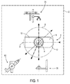
- FIG. 1 a schematic representation of a handling and case management facility containing boxes filled with plutonium oxide can be seen.
- the case has a tubular shape.
- the cases E containing the plutonium oxide boxes B are transported between the reprocessing plants and the nuclear fuel fabrication workshops in containers. When they arrive at the nuclear fuel fabrication workshops, each case is removed individually from the container and is introduced into a first glove box for introduction into a second glove box including the installation shown on the box. figure 1 .
- This second glove box is symbolized by a dashed frame and is designated by the reference 2.
- the cases are brought individually into the glove box 2 to be loaded into the handling device 4 horizontally; the cases are still sealed when loaded inside the handling device 4.
- the handling device comprises a wheel 6 mounted to rotate about its axis X, this axis being horizontal and being perpendicular to the plane of the sheet in the representation of the figure 1 .
- the wheel 6 is pivotable about its axis X so as to take different positions allowing the case to undergo different operations at these positions.
- the rotation of the wheel is provided for example by an electric motor (not shown).
- the wheel 6 comprises a housing 8 of Y axis extending diametrically in the wheel.
- the housing 8 has a first longitudinal end 10 closed and a second longitudinal end 12 open through which are introduced the cases.
- its longitudinal axis extends parallel to the Y axis of the housing.
- the second end 12 is equipped with a device for holding the case and retaining the boxes when the case is open.
- This device will be designated later "holding device” and designated by the reference 14.
- the housing 6 of case could be carried by an arm that would move in rotation and translation housing.
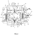
- the holding device 14 is visible on the figures 2 , 3 and 4 .
- the holding device comprises clamping means 16 of the case.
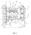
- the clamping means 16 comprise an upper jaw 18.1 and a lower jaw 18.2 ( figure 3 ).
- the upper jaws 18.1 and lower 18.2 are hingedly mounted on a frame 20.
- the upper jaw 18.1 comprises two flanges 22 extending parallel to the Y axis of the housing 8. Each flange is hingedly mounted on the frame 20 about the axis Z1.
- the lower jaw 18.2 also has two flanges 24 extending parallel to the Y axis and articulated in rotation on the frame 20 about an axis Z2 parallel to the axis Z1.
- Each jaw 18.1, 18.2 has jaws 26, 28 respectively extending between the two flanges 22, 24 respectively and intended to tighten the holster.
- the two jaws 26, 28 define, in the closed position of the jaws 18.1, 18.2, a housing corresponding to the outer section of the case.
- the holding device 14 also comprises means for actuating the jaws 18.1, 18.2 so as to bring about their bringing together or their removal by pivoting about the axes Z1, Z2 respectively.
- the flanges 22 and 24 of the upper and lower jaws have teeth meshing with each other so that the rotation of one of the jaws in one direction causes the rotation on the other side, jaws in the opposite direction, thus ensuring closing or opening synchronization of the jaws 18.1, 18.2.
- the flanges of the upper jaw 18.1 comprise four teeth meshing with three teeth of the flanges of the lower jaw 18.2.
- This embodiment also has the advantage of simplifying the device since it then has more than one actuator to simultaneously move the two jaws 18.1, 18.2.
- the displacement of one of the jaws is done by means of a single electric motor via a connecting rod articulated on one of the flanges (not shown).
- a motor for each of the jaws could be used for the actuation of each of the clamping jaws 18.1 and 18.2, the operation of the two motors then being synchronized.
- the jaw 26 of the upper jaw 18.1 has a shoulder 30 forming a longitudinal stop for the holster.
- the jaw of the lower jaw 18.2 comprises a chamfer 32 for guiding the boxes out of the case.
- This realization implements a longitudinal stop on one of the jaws and a guide on the other jaw allows a high reliability of removal of the boxes and avoids any risk of jamming due to a defect geometry or sizing of the jaws.
- the holding device 14 also comprises means forming longitudinal stop for the boxes contained in the case.
- These designated means 34 comprise an upper jaw 36 and a lower jaw 38, these jaws will be referred to as stop jaws.
- the stop jaws 36, 38 are carried by the upper jaws 18.1 and lower 18.2 in such a way that they are arranged downstream of the jaws 18.1, 18.2 in the direction of evacuation of the boxes contained in the case along the Y-axis.
- the stop jaws 36, 38 are mounted articulated on the frame 20 about the axes Z1 and Z2 respectively as the upper jaws 18.1 and lower 18.2.
- the stop jaws 36, 38 are mounted free on the upper jaws 18.1 and lower 18.2, so that the stop jaws 36, 38 can be spaced apart from each other by pivoting about the axes Z1 and Z2 independently of the jaws. 18.1 and 18.2.
- the stop jaws 36, 38 delimit between them a substantially circular passage 47 whose diameter is slightly less than the outer diameter of the boxes as can be seen on the figure 4 .
- the passage In a state ensuring the passage of boxes, the passage has a diameter slightly greater than the outer diameter of the boxes.
- the stop jaws 36, 38 are biased towards each other by elastic means 40 arranged laterally on either side of the passage of the boxes between the jaws.
- these elastic means 40 are formed by helical springs connecting the abutment jaws 36, 38.
- means for adjusting the tension of the springs 40 are provided.
- the adjustment springs are mounted on each stopper jaw by a part 44 hinged on the stopper jaws around axes Z3 and Z4 parallel to the axes Z1 and Z2 and a set screw 46 is provided to change the tension of the springs.
- the stopper jaw 36 comprises two jaws 47 defining a circular arc and the stopper jaw 38 also comprises two jaws 49 in the shape of a circular arc.
- each of the jaws 36, 38 comprises between its two jaws a roller 48 for guiding and rolling the boxes during their extraction.
- Each roller 48 is rotatably mounted about an axis parallel to the axes Z1 and Z2.
- stop jaws 36, 38 are intended to be spaced from each other by means of an external device which will be described later, this external device being further intended to recover simultaneously the boxes that are removed from the case.
- the holding device 14 comprises means for detecting the position of the stop jaws 36 and 38 relative to each other.
- these detection means comprise a single sensor 52 measuring the relative position of the two stop jaws 36 and 38.
- the sensor 52 is mounted on an arm 54 integral in movement with the stopper jaw 38 and cooperating with an integral arm 56 in movement of the abutment jaw 36.
- This sensor 52 is advantageously solely mechanical, which reduces the risk of failure compared to an electronic sensor, especially in a glove box of a fuel fabrication plant. nuclear.
- the recovery device 60 comprises an arm 62 articulated in rotation about a horizontal axis by a first end and having at a second end a receiving housing 64 boxes removed from the case. This end also comprises means for opening the abutment jaws 36, 38 formed by four fingers 66. These four fingers are intended to cooperate with the facing faces of the jaws 36, 38 and to cause their spacing one of the other away from the Y axis so as to widen the passage defined by the jaws of the abutment jaws 36, 38.
- each jaw 36, 38 comprises two rollers 70 on either side of the jaws 47, 49 intended to cooperate with the inclined ends of the fingers 66 so that these ends 68 roll on the rollers 70.
- This embodiment has the advantage of avoiding jamming and reduce wear of the fingers and stopper jaws 36, 38.
- the recovery device also includes a clip 72 which closes when it is detected that the box is found in the housing.
- a sensor is provided in the housing to determine the presence or absence of the box.
- the housing is carried by a carriage 74 movable along the axis A of the arm, which makes it possible to move the box contained in the housing and to move it to a storage carriage (not shown) in view, for example , a weighing step of the box and / or a subsequent step of opening and emptying for the manufacture of nuclear fuel MOX.
- the clamp is controlled by means of a jack and the carriage is moved by a screw-type motor.
- the installation contained in the glove box 2 comprises various stations distributed around the wheel 6. It comprises an opening device 75 of the case, comprising means for cutting one end of the case, this device for cutting is for example that described in the document FR 2 182 902 . It comprises a cutting wheel mounted in rotation and which will cut the circumference of the tube.
- the wheel 6 advantageously comprises a longitudinal displacement system along the Y axis of the holster, which is used to allow the holster to be cut, placing the holster so that its end intended to be cut out protrudes from the holster. the wheel 6 and can be cut by the wheel.
- the cutting device is disposed vertically above the wheel at an angular position of 90 ° with respect to the insertion position of the casing in the wheel 6.
- the installation also comprises the device 60 for retrieval. boxes.
- it is disposed below the wheel 6 so that the housing is oriented at 45 ° relative to a horizontal axis, which ensures a gravity evacuation of the boxes contained in the case.
- the installation may also include a recovery device 76 of the holster body when it has been completely emptied of its boxes. In the example shown, it is disposed below the wheel 6 so that the Y axis of the housing 8 is oriented vertically.
- the wheel 6 is oriented so that the Y axis of the housing 8 is also horizontal.
- the case E closed is introduced into the housing 8 for example by means of a pusher (not shown).
- the jaws 18.1 and 18.2 have been previously spaced so as to provide a passage sufficient for the passage of the case.
- the stop jaws 36 and 38 are also spaced leaving the free passage to the case E.
- the wheel 6 is then rotated by an angle of 90 ° in a counterclockwise direction so that the holding device 14 is disposed in the upper part of the wheel 6 facing the cutting device.
- the closed end of the case E located on the side of the holding device 14 will then be cut.
- the clamping jaws 18.1, 18.2 are spaced apart from each other also causing the opening of the stop jaws 36, 38.
- the displacement device along the Y axis then moves the holster which will to be moved upwards, causing the end of the case to be cut out to come out.
- the end of the case to be cut is fed into the cutting device.
- the cutting device is then actuated when the correct positioning of the case E is detected.
- the wheel cuts the tubular periphery of the case E so as to separate a head from the case of the body of the case which contains the boxes.
- the head of the case separated from the body of the case is then recovered, for example by means of a grapple and is then evacuated.
- the moving device along the Y axis lowers the body of the holster in the housing 8, and the clamping jaws 18.1 and 18.2 are closed again causing tightening of the body of the holster , the shoulder formed in the upper jaw 18.1 forming a stop for the open end of the body of the case.
- the abutment jaws 36 and 38 then form a longitudinal abutment along the Y axis for the boxes B which are now accessible through the open end of the case body ( figure 4 ).
- the wheel 6 pivots about its axis in the direction of the box recovery device.
- the wheel rotates at an angle of 135 ° in the counterclockwise direction so as to orient the Y axis of the housing along an axis of 45 ° relative to the horizontal.
- the arm of the recovery device is oriented so that its axis A is substantially aligned with the axis Y of the housing 8.
- the carriage carrying fingers 66 moves along the axis A towards the holding device 14; the fingers then penetrate between the two abutment jaws 36 and 38, and the inclined ends or ramps 68 of the fingers slide along rollers causing the spacing of the stop jaws 36 and 38 without opening the clamping jaws 18.1, 18.2.
- the passage defined by the jaws of the abutment jaws 36 and 38 is then sufficient to allow the passage of a box B.
- the box B slides naturally by gravity to the housing of the recovery device.
- the recovery device then takes the box that has just recovered for example to a weighing scale.
- a transfer device is provided for unloading the cart box and placing it on the scale.
- the body of the case is then released and, because of the force of gravity, falls into the device for recovering the case bodies.
- This device may be formed for example by a basket for recovering several body cases.
- the device for recovering them may be formed by a basket receiving several case heads.
- This handling device and management boxes containing boxes is particularly robust since it is entirely mechanical. In addition, it may comprise a reduced number of actuators since only one actuator is sufficient to control the holding device. In addition, it is very reliable, the cases being maintained by clamping and a longitudinal stop being provided which avoids any risk that the case escapes from the wheel, while facilitating the evacuation of boxes.
- the handling device according to the invention can therefore be applied in technical fields where the handling and the transfer of fragile objects are required.
Landscapes
- Engineering & Computer Science (AREA)
- Physics & Mathematics (AREA)
- General Engineering & Computer Science (AREA)
- High Energy & Nuclear Physics (AREA)
- Mechanical Engineering (AREA)
- Robotics (AREA)
- Manipulator (AREA)
- Control And Other Processes For Unpacking Of Materials (AREA)
- Specific Conveyance Elements (AREA)
- Refuse Collection And Transfer (AREA)
- Load-Engaging Elements For Cranes (AREA)
Claims (16)
- Vorrichtung zur Handhabung von Hüllen und von Kisten, die in den Hüllen enthalten sind, wobei die Hüllen eine zylindrische Form aufweisen, wobei die Vorrichtung eine Aufnahme mit einer longitudinalen Achse (Y) umfasst, die zur Aufnahme einer Hülle (E) bestimmt ist, wobei die Aufnahme (8) an einem ersten longitudinalen Ende geschlossen und an einem zweiten longitudinalen Ende offen ist, eine Haltevorrichtung (14), die im Bereich des zweiten Endes der Aufnahme (8) montiert ist, wobei die Haltevorrichtung (14) zwei Klemmbacken (18.1, 18.2) umfasst, die dazu ausgelegt sind, um eine Achse (Z1, Z2) orthogonal zur longitudinalen Achse (Y) der Aufnahme (8) herum verlagert zu werden, wobei die Klemmbacken (18.1, 18.2) dazu ausgelegt sind, eine Klemmkraft auf die Hülle (E) derart auszuüben, dass die Hülle longitudinal in der Aufnahme (8) gehalten wird, wenigstens ein Betätigungselement zum Öffnen und Schließen der Klemmbacken (18.1, 18.2), zwei Anschlagbacken (36, 38), wobei jede der Anschlagbacken (36, 38) von einer Klemmbacke (18.1, 18.2) getragen wird und frei drehbar um die Drehachse (Z1, Z2) der Klemmbacke (18.1, 18.2) gelagert ist, wobei die Anschlagbacken (36, 38) aufeinander zu in einer Anschlagposition durch elastische Mittel (40) zurückgestellt werden, derart, dass das Öffnen der Klemmbacken (18.1, 18.2) das Öffnen der Anschlagbacken (36, 38) bewirkt, und derart, dass die Anschlagbacken (36, 38) unabhängig von den Klemmbacken (18.1, 18.2) geöffnet werden können.
- Handhabungsvorrichtung nach Anspruch 1, umfassend ein Rad (6), das um seine Achse drehbeweglich ist, wobei die Aufnahme (8) in dem Rad (6) realisiert ist und sich entlang eines Durchmessers des Rads erstreckt.
- Handhabungsvorrichtung nach Anspruch 1 oder 2, bei der eine der Klemmbacken (18.1, 18.2) eine Schulter umfasst, die einen longitudinalen Anschlag für die Hülle (E) bildet, wobei die andere Klemmbacke (18.2, 18.1) vorzugsweise eine Fläche umfasst, die bezüglich der Achse (Y) der Aufnahme (8) zur Außenseite der Aufnahme (8) hin geneigt ist.
- Handhabungsvorrichtung nach einem der Ansprüche 1 bis 3, bei der wenigstens eine der Anschlagbacken (36, 38) eine drehbewegliche Rolle umfasst, die an den Durchgang angrenzt, der durch die zwei Anschlagbacken (36, 38) begrenzt wird, derart, dass das Ausführen des in der Hülle enthaltenen Objekts erleichtert wird.
- Handhabungsvorrichtung nach einem der Ansprüche 1 bis 4, bei der jede Anschlagbacke (36, 38) Öffnungsflächen auf beiden Seiten des Durchgangs umfasst, der durch die zwei Anschlagbacken (36, 38) begrenzt wird, wobei die Öffnungsflächen einer Anschlagbacke (36, 38) gegenüber den Öffnungsflächen der anderen Anschlagbacke (38, 36) sind, wobei die Öffnungsflächen dazu ausgelegt sind, jeweils mit Rampen (68) zusammenzuwirken, die von einer Öffnungsvorrichtung getragen werden, wobei die Öffnungsflächen vorzugsweise jeweils eine drehbewegliche Rolle umfassen, die mit einer der Rampen zusammenwirkt.
- Handhabungsvorrichtung nach einem der Ansprüche 1 bis 5, umfassend wenigstens einen Sensor zum Messen der Position der Anschlagbacken (36, 38), vorzugsweise einen einzigen Sensor, der die Relativposition der Anschlagbacken (36, 38) misst, wobei der Sensor von einem Arm getragen wird, der zur Bewegung mit einer der Backen (36, 38) verbunden ist und auf eine Verlagerung eines anderen Arms sensitiv ist, der zur Bewegung mit der anderen Anschlagbacke (38, 36) verbunden ist.
- Handhabungsvorrichtung nach einem der Ansprüche 1 bis 6, umfassend ein Betätigungselement zur Drehverlagerung einer der Klemmbacken (18.1, 18.2) sowie Übertragungsmittel zum Übertragen der Bewegung auf die andere Klemmbacke derart, dass ein Entfernen oder ein Annähern der Klemmbacken (18.1, 18.2) bewirkt wird.
- Handhabungsvorrichtung nach Anspruch 7, bei der die Klemmbacken (36, 38) zwei laterale Flansche umfassen, die an einem Rahmen (20) der Handhabungsvorrichtung gelagert sind, und bei der die Übertragungsmittel durch Zähne gebildet sind, die von jedem lateralen Flansch getragen werden, wobei die lateralen Flansche Zähne umfassen, die derart eingreifen, dass die Drehung in einer Richtung einer der Klemmbacken die Drehung in eine entgegengesetzte Richtung der anderen Klemmbacke (18.1, 18.2) bewirkt.
- Handhabungsvorrichtung nach einem der Ansprüche 1 bis 8, bei der die elastischen Mittel (40), die die Anschlagbacken (36, 38) zurückstellen, zwei Schraubenfedern umfassen, die auf beiden Seiten der longitudinalen Achse (Y) der Aufnahme (8) angeordnet sind, wobei jede Schraubenfeder an einem Ende an einer Anschlagbacke (36, 38) befestigt ist und an einem anderen Ende an der anderen Anschlagbacke (38, 36), wobei die Vorrichtung vorzugsweise Mittel zur Regelung der Spannung der Federn umfasst.
- Handhabungsvorrichtung nach einem der Ansprüche 1 bis 9, umfassend eine Vorrichtung zur Verlagerung der Hülle entlang der longitudinalen Achse (Y) der Aufnahme (8), die in der Aufnahme (8) angeordnet ist.
- Anlage zur Handhabung einer Hülle und von Kisten, die in der Hülle enthalten sind, umfassend eine Handhabungsvorrichtung nach einem der Ansprüche 1 bis 10, eine Vorrichtung zum Öffnen von Hüllen zum Separieren eines Hüllenkopfs von einem Hüllenkörper und Zugänglichmachen der in der Hülle enthaltenen Objekte, sowie eine Vorrichtung zur Extraktion und zum Aufsammeln der in den Hüllen enthaltenen Objekte.
- Anlage nach Anspruch 11 in Kombination mit Anspruch 2, bei der die Vorrichtung zum Öffnen von Hüllen und die Vorrichtung zur Extraktion und zum Aufsammeln der in den Hüllen enthaltenen Objekte um ein Rad (6) herum angeordnet sind.
- Anlage nach Anspruch 12, bei der die Vorrichtung zum Öffnen von Hüllen eine Schneidvorrichtung ist, die über dem Rad (6) angeordnet ist, und die Vorrichtung zur Extraktion und zum Aufsammeln unter dem Rad (6) derart angeordnet ist, dass die Extraktion der Objekte aus dem Hüllenkörper durch Schwerkraft erzielt wird, wobei die longitudinale Achse (Y) der Aufnahme (8) während der Extraktion der Objekte vorzugsweise unter einem Winkel von 45° bezüglich einer horizontalen Richtung orientiert ist.
- Anlage nach einem der Ansprüche 11 bis 13, bei der die Vorrichtung zur Extraktion und zum Aufsammeln einen Arm mit longitudinaler Achse (A) umfasst, der wenigstens in Drehung um eine Achse parallel zur Achse des Rads (6) verlagerbar ist, einen Wagen, der translationsbeweglich an dem Arm entlang der longitudinalen Achse (A) des Arms montiert ist, eine von dem Wagen getragene Aufnahme, die dazu ausgelegt ist, ein in der Hülle enthaltenes Objekt zu empfangen, sowie Mittel (66, 68) zum Öffnen der Anschlagbacken (36, 38), wobei der Wagen Mittel zur Erfassung des Vorhandenseins des Objekts umfasst, und/oder die Mittel (66, 68) zum Öffnen der Anschlagbacken (36, 38) vorzugsweise vier Finger (66) umfassen, die von dem Wagen getragen werden und an die Aufnahme angrenzen, wobei die Finger (66) parallel zur longitudinalen Achse (A) des Arms orientiert sind und jeweils an einem freien Ende mit einer Rampe (68) ausgestattet sind, die dazu ausgelegt ist, mit den Anschlagbacken (36, 38) derart zusammenzuwirken, dass dann, wenn die Finger (66) zwischen die Anschlagbacken (36, 38) eingeführt werden, diese sich voneinander beabstanden.
- Anlage nach einem der Ansprüche 11 bis 14, umfassend eine Vorrichtung zum Aufsammeln der leeren Hülle, die unter dem Rad derart angeordnet ist, dass die Entfernung des leeren Hüllenkörpers durch Schwerkraft erzielt wird, sowie eine Vorrichtung zum Aufsammeln der Hüllenköpfe.
- Anlage nach einem der Ansprüche 11 bis 15, bei der die Objekte Kisten sind, die Plutoniumoxid enthalten, und die Anlage in einem Handschuhkasten eingeschlossen ist.
Applications Claiming Priority (2)
| Application Number | Priority Date | Filing Date | Title |
|---|---|---|---|
| FR1256810A FR2993194B1 (fr) | 2012-07-13 | 2012-07-13 | Dispositif de manutention d'etuis contenant des objets |
| PCT/EP2013/064691 WO2014009476A1 (fr) | 2012-07-13 | 2013-07-11 | Dispositif de manutention d'etuis contenant des objets |
Publications (2)
| Publication Number | Publication Date |
|---|---|
| EP2872300A1 EP2872300A1 (de) | 2015-05-20 |
| EP2872300B1 true EP2872300B1 (de) | 2016-08-17 |
Family
ID=47137831
Family Applications (1)
| Application Number | Title | Priority Date | Filing Date |
|---|---|---|---|
| EP13735292.8A Active EP2872300B1 (de) | 2012-07-13 | 2013-07-11 | Vorrichtung zur handhabung von behältern mit gegenständen |
Country Status (7)
| Country | Link |
|---|---|
| US (1) | US9649769B2 (de) |
| EP (1) | EP2872300B1 (de) |
| JP (1) | JP6294877B2 (de) |
| CN (1) | CN104619469B (de) |
| FR (1) | FR2993194B1 (de) |
| RU (1) | RU2633204C2 (de) |
| WO (1) | WO2014009476A1 (de) |
Families Citing this family (1)
| Publication number | Priority date | Publication date | Assignee | Title |
|---|---|---|---|---|
| CN108590672B (zh) * | 2018-05-03 | 2020-11-20 | 深圳市市政工程总公司 | 一种手持式隧道破碎设备用辅助机构及其操作方法 |
Family Cites Families (22)
| Publication number | Priority date | Publication date | Assignee | Title |
|---|---|---|---|---|
| US2106373A (en) * | 1938-01-25 | Cable and pipe clutch | ||
| US1974892A (en) * | 1932-11-30 | 1934-09-25 | Canal Storage Company Inc | Brick lifter |
| US3040921A (en) * | 1958-06-18 | 1962-06-26 | United States Steel Corp | Plate handling apparatus |
| US3771826A (en) * | 1969-05-16 | 1973-11-13 | Amerola Prod Corp | Adjustable material handling device |
| NL7304097A (de) | 1972-03-25 | 1973-09-27 | ||
| US3941413A (en) * | 1974-06-04 | 1976-03-02 | The United States Of America As Represented By The United States Energy Research And Development Administration | Quick release latch for reactor scram |
| JPS5959378A (ja) * | 1982-09-28 | 1984-04-05 | 住友電気工業株式会社 | ロボツトハンドの把持ミス検出装置 |
| JPH039960Y2 (de) * | 1986-11-13 | 1991-03-12 | ||
| FR2682902B1 (fr) | 1991-10-29 | 1995-10-27 | Cogema | Machine pour couper des gaines circonferentielles. |
| DE4400354A1 (de) * | 1994-01-08 | 1995-07-13 | Gerhard H Kottemann | An einem Revolver einer Drehmaschine ansetzbarer Stangengreifer |
| JP3283735B2 (ja) * | 1995-10-18 | 2002-05-20 | 株式会社日立製作所 | 原子炉格納容器上部ドライウェルの建設方法及びその建設方法に用いるモジュール |
| US6331025B1 (en) * | 2000-07-12 | 2001-12-18 | William E. Douglas | Barrier lifter |
| NL1017575C2 (nl) * | 2000-10-13 | 2002-04-16 | Albertus Jacobus Gertrude Mari | Beveiliging voor hijsklem voor bouwelementen. |
| FR2879490B1 (fr) * | 2004-12-21 | 2007-03-23 | Tech En Milieu Ionisant Stmi S | Dispositif d'intervention motorise pour boite a gant et boite a gant equipee d'un tel dispositif |
| US7455338B2 (en) * | 2005-10-07 | 2008-11-25 | Jenney Alfred P | Leveling device for lifting apparatus and associated methods |
| RU56704U1 (ru) * | 2006-04-10 | 2006-09-10 | Общество с ограниченной ответственностью "Инженерный центр ядерных контейнеров" (ООО ИЦЯК) | Транспортный упаковочный комплект для транспортирования и хранения отработавших тепловыделяющих сборок |
| US8104810B2 (en) * | 2006-11-01 | 2012-01-31 | Norgren Automotive Solutions, Inc. | Gripper having sensor for detecting displacement |
| JP4811951B2 (ja) * | 2007-08-23 | 2011-11-09 | 独立行政法人日本原子力研究開発機構 | 放射化された金属材料及び放射性ガスを含む密閉容器の切断・開封装置 |
| JP2009255262A (ja) * | 2008-04-21 | 2009-11-05 | Ko Monken | 把持装置ヘッド |
| US8550413B2 (en) * | 2010-04-29 | 2013-10-08 | Hach Company | Self-centering vial clamp |
| FR2964091B1 (fr) * | 2010-08-26 | 2012-09-28 | Areva Nc | Dispositif de manutention de futs, installation de transfert de materiau en poudre et procede de transfert |
| FR2984790B1 (fr) | 2011-12-22 | 2014-02-21 | Areva Nc | Dispositif de manipulation d'objets en boites a gants |
-
2012
- 2012-07-13 FR FR1256810A patent/FR2993194B1/fr not_active Expired - Fee Related
-
2013
- 2013-07-11 EP EP13735292.8A patent/EP2872300B1/de active Active
- 2013-07-11 CN CN201380047655.8A patent/CN104619469B/zh active Active
- 2013-07-11 RU RU2015104861A patent/RU2633204C2/ru not_active IP Right Cessation
- 2013-07-11 WO PCT/EP2013/064691 patent/WO2014009476A1/fr active Application Filing
- 2013-07-11 US US14/414,238 patent/US9649769B2/en not_active Expired - Fee Related
- 2013-07-11 JP JP2015520993A patent/JP6294877B2/ja active Active
Also Published As
| Publication number | Publication date |
|---|---|
| RU2633204C2 (ru) | 2017-10-11 |
| EP2872300A1 (de) | 2015-05-20 |
| US9649769B2 (en) | 2017-05-16 |
| FR2993194B1 (fr) | 2014-08-22 |
| CN104619469A (zh) | 2015-05-13 |
| JP2015529565A (ja) | 2015-10-08 |
| WO2014009476A1 (fr) | 2014-01-16 |
| CN104619469B (zh) | 2017-03-08 |
| JP6294877B2 (ja) | 2018-03-14 |
| RU2015104861A (ru) | 2016-09-10 |
| US20150197013A1 (en) | 2015-07-16 |
| FR2993194A1 (fr) | 2014-01-17 |
Similar Documents
| Publication | Publication Date | Title |
|---|---|---|
| EP2647462B1 (de) | Elektrodenwechsler mit translatorischem Antrieb von Greiffern | |
| FR3010119A1 (fr) | Dispositif de connexion etanche a securite de fonctionnement amelioree | |
| CH639045A5 (fr) | Dispositif pour introduire des paquets de feuilles dans une machine les travaillant. | |
| EP2617040B1 (de) | Vorrichtung zur trockenhandhabung von kernbrennstabbündeln | |
| EP3042380B1 (de) | Vorrichtung zur bereitstellung einer fluiddichten verbindung in zwei eingeschlossenen volumina mit vorrichtung zum halten vor der verbindung | |
| FR3010118A1 (fr) | Enceinte etanche comportant un mecanisme de commande d'ouverture et de fermeture pour un dispositif de connexion etanche entre deux volumes clos | |
| EP0123598B1 (de) | Drehbarer Transport- und Ersatzbehälter für verunreinigte Teile und Ergänzungsetui für diesen Behälter | |
| FR2747111A1 (fr) | Systeme d'accouplement pour un transfert confine d'un objet plat d'une boite de confinement vers une unite de traitement de l'objet | |
| EP2872300B1 (de) | Vorrichtung zur handhabung von behältern mit gegenständen | |
| EP2100309B1 (de) | Einrichtung zum transfer von kernbrennstoffkassetten zwischen einem transportbehälter und einer lagereinrichtung | |
| EP3694802B1 (de) | Greifvorrichtung für schalen | |
| EP0682222A1 (de) | Automatische Ladevorrichtung für einen Ofen im Weltraum | |
| EP3491327B1 (de) | Vorrichtung zur verriegeln einer granate und trage mit solch einer verriegelungsvorrichtung | |
| FR2998271A1 (fr) | Machine d'emballage de bagages | |
| FR2810297A1 (fr) | Distributeur automatique de couvercles sur des boites | |
| WO2007017519A1 (fr) | Emballage destine a recevoir un etui contenant des matieres radioactives, et procede de transfert d'un tel etui | |
| EP3280564B1 (de) | Anordnung zum einsatz eines thermoelements in eine rohrförmige leitung und verfahren hierzu | |
| EP1573750B1 (de) | Vorrichtung zum Transportieren von Kernbrennelementen | |
| EP2789550B1 (de) | Handhabungs- und Begrenzungshaube, Anwendung zur Handhabung von Probengefäßen für nukleares Material, insbesondere Kernbrennstoffe | |
| EP2358616B1 (de) | Transferstation und verfahren für einen pneumatischen gutträger | |
| EP0639775B1 (de) | Vorrichtung zur Lagerung von zylindrischen Gegenständen, mit schneller Be- und Entladung | |
| EP1946330B1 (de) | Brennstoffmantelungs-schutzkragen, verfahren zum herstellen von brennstoffstäben und einrichtung zum ausführen des verfahrens | |
| EP0600786A1 (de) | Automatische Ladevorrichtung für einen Ofen im Weltraum | |
| EP2852956B1 (de) | Speichervorrichtung | |
| FR2706582A1 (fr) | Installation automatique de traitement des chapeaux de bouteilles de gaz. |
Legal Events
| Date | Code | Title | Description |
|---|---|---|---|
| PUAI | Public reference made under article 153(3) epc to a published international application that has entered the european phase |
Free format text: ORIGINAL CODE: 0009012 |
|
| 17P | Request for examination filed |
Effective date: 20150122 |
|
| AK | Designated contracting states |
Kind code of ref document: A1 Designated state(s): AL AT BE BG CH CY CZ DE DK EE ES FI FR GB GR HR HU IE IS IT LI LT LU LV MC MK MT NL NO PL PT RO RS SE SI SK SM TR |
|
| AX | Request for extension of the european patent |
Extension state: BA ME |
|
| RIN1 | Information on inventor provided before grant (corrected) |
Inventor name: COLIN, BRUNO Inventor name: COLLETTE, LUC |
|
| RIN1 | Information on inventor provided before grant (corrected) |
Inventor name: COLIN, BRUNO Inventor name: COLLETTE, LUC |
|
| DAX | Request for extension of the european patent (deleted) | ||
| RIN1 | Information on inventor provided before grant (corrected) |
Inventor name: COLLETTE, LUC Inventor name: COLIN, BRUNO |
|
| REG | Reference to a national code |
Ref country code: DE Ref legal event code: R079 Ref document number: 602013010385 Country of ref document: DE Free format text: PREVIOUS MAIN CLASS: B25J0015000000 Ipc: G21F0007040000 |
|
| GRAP | Despatch of communication of intention to grant a patent |
Free format text: ORIGINAL CODE: EPIDOSNIGR1 |
|
| RIC1 | Information provided on ipc code assigned before grant |
Ipc: B25J 11/00 20060101ALI20160127BHEP Ipc: G21F 7/04 20060101AFI20160127BHEP Ipc: G21F 7/06 20060101ALI20160127BHEP Ipc: B65G 65/38 20060101ALI20160127BHEP |
|
| INTG | Intention to grant announced |
Effective date: 20160212 |
|
| GRAS | Grant fee paid |
Free format text: ORIGINAL CODE: EPIDOSNIGR3 |
|
| GRAA | (expected) grant |
Free format text: ORIGINAL CODE: 0009210 |
|
| AK | Designated contracting states |
Kind code of ref document: B1 Designated state(s): AL AT BE BG CH CY CZ DE DK EE ES FI FR GB GR HR HU IE IS IT LI LT LU LV MC MK MT NL NO PL PT RO RS SE SI SK SM TR |
|
| REG | Reference to a national code |
Ref country code: GB Ref legal event code: FG4D Free format text: NOT ENGLISH |
|
| REG | Reference to a national code |
Ref country code: CH Ref legal event code: EP |
|
| REG | Reference to a national code |
Ref country code: IE Ref legal event code: FG4D Free format text: LANGUAGE OF EP DOCUMENT: FRENCH |
|
| REG | Reference to a national code |
Ref country code: AT Ref legal event code: REF Ref document number: 821761 Country of ref document: AT Kind code of ref document: T Effective date: 20160915 |
|
| REG | Reference to a national code |
Ref country code: DE Ref legal event code: R096 Ref document number: 602013010385 Country of ref document: DE |
|
| REG | Reference to a national code |
Ref country code: NL Ref legal event code: MP Effective date: 20160817 |
|
| REG | Reference to a national code |
Ref country code: LT Ref legal event code: MG4D |
|
| REG | Reference to a national code |
Ref country code: AT Ref legal event code: MK05 Ref document number: 821761 Country of ref document: AT Kind code of ref document: T Effective date: 20160817 |
|
| PG25 | Lapsed in a contracting state [announced via postgrant information from national office to epo] |
Ref country code: NL Free format text: LAPSE BECAUSE OF FAILURE TO SUBMIT A TRANSLATION OF THE DESCRIPTION OR TO PAY THE FEE WITHIN THE PRESCRIBED TIME-LIMIT Effective date: 20160817 Ref country code: IT Free format text: LAPSE BECAUSE OF FAILURE TO SUBMIT A TRANSLATION OF THE DESCRIPTION OR TO PAY THE FEE WITHIN THE PRESCRIBED TIME-LIMIT Effective date: 20160817 Ref country code: RS Free format text: LAPSE BECAUSE OF FAILURE TO SUBMIT A TRANSLATION OF THE DESCRIPTION OR TO PAY THE FEE WITHIN THE PRESCRIBED TIME-LIMIT Effective date: 20160817 Ref country code: HR Free format text: LAPSE BECAUSE OF FAILURE TO SUBMIT A TRANSLATION OF THE DESCRIPTION OR TO PAY THE FEE WITHIN THE PRESCRIBED TIME-LIMIT Effective date: 20160817 Ref country code: NO Free format text: LAPSE BECAUSE OF FAILURE TO SUBMIT A TRANSLATION OF THE DESCRIPTION OR TO PAY THE FEE WITHIN THE PRESCRIBED TIME-LIMIT Effective date: 20161117 Ref country code: FI Free format text: LAPSE BECAUSE OF FAILURE TO SUBMIT A TRANSLATION OF THE DESCRIPTION OR TO PAY THE FEE WITHIN THE PRESCRIBED TIME-LIMIT Effective date: 20160817 Ref country code: LT Free format text: LAPSE BECAUSE OF FAILURE TO SUBMIT A TRANSLATION OF THE DESCRIPTION OR TO PAY THE FEE WITHIN THE PRESCRIBED TIME-LIMIT Effective date: 20160817 |
|
| PG25 | Lapsed in a contracting state [announced via postgrant information from national office to epo] |
Ref country code: ES Free format text: LAPSE BECAUSE OF FAILURE TO SUBMIT A TRANSLATION OF THE DESCRIPTION OR TO PAY THE FEE WITHIN THE PRESCRIBED TIME-LIMIT Effective date: 20160817 Ref country code: LV Free format text: LAPSE BECAUSE OF FAILURE TO SUBMIT A TRANSLATION OF THE DESCRIPTION OR TO PAY THE FEE WITHIN THE PRESCRIBED TIME-LIMIT Effective date: 20160817 Ref country code: AT Free format text: LAPSE BECAUSE OF FAILURE TO SUBMIT A TRANSLATION OF THE DESCRIPTION OR TO PAY THE FEE WITHIN THE PRESCRIBED TIME-LIMIT Effective date: 20160817 Ref country code: SE Free format text: LAPSE BECAUSE OF FAILURE TO SUBMIT A TRANSLATION OF THE DESCRIPTION OR TO PAY THE FEE WITHIN THE PRESCRIBED TIME-LIMIT Effective date: 20160817 Ref country code: GR Free format text: LAPSE BECAUSE OF FAILURE TO SUBMIT A TRANSLATION OF THE DESCRIPTION OR TO PAY THE FEE WITHIN THE PRESCRIBED TIME-LIMIT Effective date: 20161118 Ref country code: PT Free format text: LAPSE BECAUSE OF FAILURE TO SUBMIT A TRANSLATION OF THE DESCRIPTION OR TO PAY THE FEE WITHIN THE PRESCRIBED TIME-LIMIT Effective date: 20161219 Ref country code: PL Free format text: LAPSE BECAUSE OF FAILURE TO SUBMIT A TRANSLATION OF THE DESCRIPTION OR TO PAY THE FEE WITHIN THE PRESCRIBED TIME-LIMIT Effective date: 20160817 |
|
| PG25 | Lapsed in a contracting state [announced via postgrant information from national office to epo] |
Ref country code: EE Free format text: LAPSE BECAUSE OF FAILURE TO SUBMIT A TRANSLATION OF THE DESCRIPTION OR TO PAY THE FEE WITHIN THE PRESCRIBED TIME-LIMIT Effective date: 20160817 Ref country code: RO Free format text: LAPSE BECAUSE OF FAILURE TO SUBMIT A TRANSLATION OF THE DESCRIPTION OR TO PAY THE FEE WITHIN THE PRESCRIBED TIME-LIMIT Effective date: 20160817 |
|
| REG | Reference to a national code |
Ref country code: DE Ref legal event code: R097 Ref document number: 602013010385 Country of ref document: DE |
|
| PG25 | Lapsed in a contracting state [announced via postgrant information from national office to epo] |
Ref country code: SK Free format text: LAPSE BECAUSE OF FAILURE TO SUBMIT A TRANSLATION OF THE DESCRIPTION OR TO PAY THE FEE WITHIN THE PRESCRIBED TIME-LIMIT Effective date: 20160817 Ref country code: SM Free format text: LAPSE BECAUSE OF FAILURE TO SUBMIT A TRANSLATION OF THE DESCRIPTION OR TO PAY THE FEE WITHIN THE PRESCRIBED TIME-LIMIT Effective date: 20160817 Ref country code: CZ Free format text: LAPSE BECAUSE OF FAILURE TO SUBMIT A TRANSLATION OF THE DESCRIPTION OR TO PAY THE FEE WITHIN THE PRESCRIBED TIME-LIMIT Effective date: 20160817 Ref country code: BG Free format text: LAPSE BECAUSE OF FAILURE TO SUBMIT A TRANSLATION OF THE DESCRIPTION OR TO PAY THE FEE WITHIN THE PRESCRIBED TIME-LIMIT Effective date: 20161117 Ref country code: DK Free format text: LAPSE BECAUSE OF FAILURE TO SUBMIT A TRANSLATION OF THE DESCRIPTION OR TO PAY THE FEE WITHIN THE PRESCRIBED TIME-LIMIT Effective date: 20160817 |
|
| PLBE | No opposition filed within time limit |
Free format text: ORIGINAL CODE: 0009261 |
|
| STAA | Information on the status of an ep patent application or granted ep patent |
Free format text: STATUS: NO OPPOSITION FILED WITHIN TIME LIMIT |
|
| 26N | No opposition filed |
Effective date: 20170518 |
|
| REG | Reference to a national code |
Ref country code: FR Ref legal event code: PLFP Year of fee payment: 5 |
|
| PG25 | Lapsed in a contracting state [announced via postgrant information from national office to epo] |
Ref country code: SI Free format text: LAPSE BECAUSE OF FAILURE TO SUBMIT A TRANSLATION OF THE DESCRIPTION OR TO PAY THE FEE WITHIN THE PRESCRIBED TIME-LIMIT Effective date: 20160817 |
|
| REG | Reference to a national code |
Ref country code: DE Ref legal event code: R119 Ref document number: 602013010385 Country of ref document: DE |
|
| REG | Reference to a national code |
Ref country code: CH Ref legal event code: PL |
|
| REG | Reference to a national code |
Ref country code: IE Ref legal event code: MM4A |
|
| PG25 | Lapsed in a contracting state [announced via postgrant information from national office to epo] |
Ref country code: CH Free format text: LAPSE BECAUSE OF NON-PAYMENT OF DUE FEES Effective date: 20170731 Ref country code: LI Free format text: LAPSE BECAUSE OF NON-PAYMENT OF DUE FEES Effective date: 20170731 Ref country code: IE Free format text: LAPSE BECAUSE OF NON-PAYMENT OF DUE FEES Effective date: 20170711 Ref country code: DE Free format text: LAPSE BECAUSE OF NON-PAYMENT OF DUE FEES Effective date: 20180201 |
|
| REG | Reference to a national code |
Ref country code: BE Ref legal event code: MM Effective date: 20170731 |
|
| PG25 | Lapsed in a contracting state [announced via postgrant information from national office to epo] |
Ref country code: LU Free format text: LAPSE BECAUSE OF NON-PAYMENT OF DUE FEES Effective date: 20170711 |
|
| REG | Reference to a national code |
Ref country code: FR Ref legal event code: PLFP Year of fee payment: 6 |
|
| PG25 | Lapsed in a contracting state [announced via postgrant information from national office to epo] |
Ref country code: BE Free format text: LAPSE BECAUSE OF NON-PAYMENT OF DUE FEES Effective date: 20170731 |
|
| PG25 | Lapsed in a contracting state [announced via postgrant information from national office to epo] |
Ref country code: MT Free format text: LAPSE BECAUSE OF FAILURE TO SUBMIT A TRANSLATION OF THE DESCRIPTION OR TO PAY THE FEE WITHIN THE PRESCRIBED TIME-LIMIT Effective date: 20160817 |
|
| PG25 | Lapsed in a contracting state [announced via postgrant information from national office to epo] |
Ref country code: AL Free format text: LAPSE BECAUSE OF FAILURE TO SUBMIT A TRANSLATION OF THE DESCRIPTION OR TO PAY THE FEE WITHIN THE PRESCRIBED TIME-LIMIT Effective date: 20160817 |
|
| PG25 | Lapsed in a contracting state [announced via postgrant information from national office to epo] |
Ref country code: HU Free format text: LAPSE BECAUSE OF FAILURE TO SUBMIT A TRANSLATION OF THE DESCRIPTION OR TO PAY THE FEE WITHIN THE PRESCRIBED TIME-LIMIT; INVALID AB INITIO Effective date: 20130711 Ref country code: MC Free format text: LAPSE BECAUSE OF FAILURE TO SUBMIT A TRANSLATION OF THE DESCRIPTION OR TO PAY THE FEE WITHIN THE PRESCRIBED TIME-LIMIT Effective date: 20160817 |
|
| PG25 | Lapsed in a contracting state [announced via postgrant information from national office to epo] |
Ref country code: CY Free format text: LAPSE BECAUSE OF FAILURE TO SUBMIT A TRANSLATION OF THE DESCRIPTION OR TO PAY THE FEE WITHIN THE PRESCRIBED TIME-LIMIT Effective date: 20160817 |
|
| PG25 | Lapsed in a contracting state [announced via postgrant information from national office to epo] |
Ref country code: MK Free format text: LAPSE BECAUSE OF FAILURE TO SUBMIT A TRANSLATION OF THE DESCRIPTION OR TO PAY THE FEE WITHIN THE PRESCRIBED TIME-LIMIT Effective date: 20160817 |
|
| PG25 | Lapsed in a contracting state [announced via postgrant information from national office to epo] |
Ref country code: TR Free format text: LAPSE BECAUSE OF FAILURE TO SUBMIT A TRANSLATION OF THE DESCRIPTION OR TO PAY THE FEE WITHIN THE PRESCRIBED TIME-LIMIT Effective date: 20160817 |
|
| PG25 | Lapsed in a contracting state [announced via postgrant information from national office to epo] |
Ref country code: IS Free format text: LAPSE BECAUSE OF FAILURE TO SUBMIT A TRANSLATION OF THE DESCRIPTION OR TO PAY THE FEE WITHIN THE PRESCRIBED TIME-LIMIT Effective date: 20161217 |
|
| REG | Reference to a national code |
Ref country code: GB Ref legal event code: 732E Free format text: REGISTERED BETWEEN 20220217 AND 20220223 |
|
| PGFP | Annual fee paid to national office [announced via postgrant information from national office to epo] |
Ref country code: GB Payment date: 20240722 Year of fee payment: 12 |
|
| PGFP | Annual fee paid to national office [announced via postgrant information from national office to epo] |
Ref country code: FR Payment date: 20240723 Year of fee payment: 12 |