EP2416990B1 - Blende für ein kraftfahrzeug - Google Patents
Blende für ein kraftfahrzeug Download PDFInfo
- Publication number
- EP2416990B1 EP2416990B1 EP10713571.7A EP10713571A EP2416990B1 EP 2416990 B1 EP2416990 B1 EP 2416990B1 EP 10713571 A EP10713571 A EP 10713571A EP 2416990 B1 EP2416990 B1 EP 2416990B1
- Authority
- EP
- European Patent Office
- Prior art keywords
- component
- keypad
- vehicle
- trim according
- sensor
- Prior art date
- Legal status (The legal status is an assumption and is not a legal conclusion. Google has not performed a legal analysis and makes no representation as to the accuracy of the status listed.)
- Not-in-force
Links
- 239000004033 plastic Substances 0.000 claims description 16
- 229920003023 plastic Polymers 0.000 claims description 16
- 238000001746 injection moulding Methods 0.000 claims description 9
- 239000012815 thermoplastic material Substances 0.000 claims description 6
- 229920003229 poly(methyl methacrylate) Polymers 0.000 claims description 4
- 239000004926 polymethyl methacrylate Substances 0.000 claims description 4
- 238000005034 decoration Methods 0.000 claims 1
- 239000010410 layer Substances 0.000 description 6
- 230000002093 peripheral effect Effects 0.000 description 6
- 238000000034 method Methods 0.000 description 5
- 238000011161 development Methods 0.000 description 4
- 230000018109 developmental process Effects 0.000 description 4
- 230000003678 scratch resistant effect Effects 0.000 description 3
- 239000011248 coating agent Substances 0.000 description 2
- 238000000576 coating method Methods 0.000 description 2
- 238000012986 modification Methods 0.000 description 2
- 230000004048 modification Effects 0.000 description 2
- 206010052128 Glare Diseases 0.000 description 1
- 239000000853 adhesive Substances 0.000 description 1
- 230000001070 adhesive effect Effects 0.000 description 1
- 238000013475 authorization Methods 0.000 description 1
- 239000011324 bead Substances 0.000 description 1
- 125000000484 butyl group Chemical group [H]C([*])([H])C([H])([H])C([H])([H])C([H])([H])[H] 0.000 description 1
- 238000005253 cladding Methods 0.000 description 1
- 239000003086 colorant Substances 0.000 description 1
- 239000000470 constituent Substances 0.000 description 1
- 238000013461 design Methods 0.000 description 1
- 239000011888 foil Substances 0.000 description 1
- 238000003780 insertion Methods 0.000 description 1
- 230000037431 insertion Effects 0.000 description 1
- 230000010354 integration Effects 0.000 description 1
- 239000002346 layers by function Substances 0.000 description 1
- 238000004519 manufacturing process Methods 0.000 description 1
- 230000005226 mechanical processes and functions Effects 0.000 description 1
- 238000007789 sealing Methods 0.000 description 1
- 239000000243 solution Substances 0.000 description 1
- 239000007921 spray Substances 0.000 description 1
- 229920001169 thermoplastic Polymers 0.000 description 1
- 239000004416 thermosoftening plastic Substances 0.000 description 1
- 238000005406 washing Methods 0.000 description 1
Images




Classifications
-
- B—PERFORMING OPERATIONS; TRANSPORTING
- B60—VEHICLES IN GENERAL
- B60R—VEHICLES, VEHICLE FITTINGS, OR VEHICLE PARTS, NOT OTHERWISE PROVIDED FOR
- B60R13/00—Elements for body-finishing, identifying, or decorating; Arrangements or adaptations for advertising purposes
- B60R13/04—External Ornamental or guard strips; Ornamental inscriptive devices thereon
-
- B—PERFORMING OPERATIONS; TRANSPORTING
- B60—VEHICLES IN GENERAL
- B60R—VEHICLES, VEHICLE FITTINGS, OR VEHICLE PARTS, NOT OTHERWISE PROVIDED FOR
- B60R11/00—Arrangements for holding or mounting articles, not otherwise provided for
- B60R11/02—Arrangements for holding or mounting articles, not otherwise provided for for radio sets, television sets, telephones, or the like; Arrangement of controls thereof
- B60R11/0229—Arrangements for holding or mounting articles, not otherwise provided for for radio sets, television sets, telephones, or the like; Arrangement of controls thereof for displays, e.g. cathodic tubes
- B60R11/0235—Arrangements for holding or mounting articles, not otherwise provided for for radio sets, television sets, telephones, or the like; Arrangement of controls thereof for displays, e.g. cathodic tubes of flat type, e.g. LCD
-
- B—PERFORMING OPERATIONS; TRANSPORTING
- B60—VEHICLES IN GENERAL
- B60R—VEHICLES, VEHICLE FITTINGS, OR VEHICLE PARTS, NOT OTHERWISE PROVIDED FOR
- B60R13/00—Elements for body-finishing, identifying, or decorating; Arrangements or adaptations for advertising purposes
- B60R13/02—Internal Trim mouldings ; Internal Ledges; Wall liners for passenger compartments; Roof liners
-
- B—PERFORMING OPERATIONS; TRANSPORTING
- B60—VEHICLES IN GENERAL
- B60R—VEHICLES, VEHICLE FITTINGS, OR VEHICLE PARTS, NOT OTHERWISE PROVIDED FOR
- B60R13/00—Elements for body-finishing, identifying, or decorating; Arrangements or adaptations for advertising purposes
- B60R13/02—Internal Trim mouldings ; Internal Ledges; Wall liners for passenger compartments; Roof liners
- B60R13/0237—Side or rear panels
- B60R13/0243—Doors
-
- B—PERFORMING OPERATIONS; TRANSPORTING
- B60—VEHICLES IN GENERAL
- B60R—VEHICLES, VEHICLE FITTINGS, OR VEHICLE PARTS, NOT OTHERWISE PROVIDED FOR
- B60R13/00—Elements for body-finishing, identifying, or decorating; Arrangements or adaptations for advertising purposes
- B60R13/02—Internal Trim mouldings ; Internal Ledges; Wall liners for passenger compartments; Roof liners
- B60R13/0237—Side or rear panels
- B60R13/025—Pillars; Roof rails
-
- B—PERFORMING OPERATIONS; TRANSPORTING
- B60—VEHICLES IN GENERAL
- B60R—VEHICLES, VEHICLE FITTINGS, OR VEHICLE PARTS, NOT OTHERWISE PROVIDED FOR
- B60R25/00—Fittings or systems for preventing or indicating unauthorised use or theft of vehicles
- B60R25/01—Fittings or systems for preventing or indicating unauthorised use or theft of vehicles operating on vehicle systems or fittings, e.g. on doors, seats or windscreens
-
- B—PERFORMING OPERATIONS; TRANSPORTING
- B60—VEHICLES IN GENERAL
- B60R—VEHICLES, VEHICLE FITTINGS, OR VEHICLE PARTS, NOT OTHERWISE PROVIDED FOR
- B60R25/00—Fittings or systems for preventing or indicating unauthorised use or theft of vehicles
- B60R25/20—Means to switch the anti-theft system on or off
- B60R25/23—Means to switch the anti-theft system on or off using manual input of alphanumerical codes
-
- B—PERFORMING OPERATIONS; TRANSPORTING
- B62—LAND VEHICLES FOR TRAVELLING OTHERWISE THAN ON RAILS
- B62D—MOTOR VEHICLES; TRAILERS
- B62D25/00—Superstructure or monocoque structure sub-units; Parts or details thereof not otherwise provided for
- B62D25/04—Door pillars ; windshield pillars
-
- B—PERFORMING OPERATIONS; TRANSPORTING
- B60—VEHICLES IN GENERAL
- B60R—VEHICLES, VEHICLE FITTINGS, OR VEHICLE PARTS, NOT OTHERWISE PROVIDED FOR
- B60R11/00—Arrangements for holding or mounting articles, not otherwise provided for
- B60R2011/0042—Arrangements for holding or mounting articles, not otherwise provided for characterised by mounting means
- B60R2011/0049—Arrangements for holding or mounting articles, not otherwise provided for characterised by mounting means for non integrated articles
- B60R2011/0064—Connection with the article
- B60R2011/0071—Connection with the article using latches, clips, clamps, straps or the like
-
- B—PERFORMING OPERATIONS; TRANSPORTING
- B60—VEHICLES IN GENERAL
- B60R—VEHICLES, VEHICLE FITTINGS, OR VEHICLE PARTS, NOT OTHERWISE PROVIDED FOR
- B60R13/00—Elements for body-finishing, identifying, or decorating; Arrangements or adaptations for advertising purposes
- B60R13/02—Internal Trim mouldings ; Internal Ledges; Wall liners for passenger compartments; Roof liners
- B60R2013/0287—Internal Trim mouldings ; Internal Ledges; Wall liners for passenger compartments; Roof liners integrating other functions or accessories
Definitions
- the invention relates to a panel or other trim part made of plastic for a vehicle, in particular for a motor vehicle, with a first component made of plastic and with a second component made of plastic.
- Such a panel is from the EP 1 695 808 A1 known.
- the prior art panel comprises a first component made of plastic, namely a cover part made of a thermoplastic material, and a second component made of plastic, namely a carrier part made of a thermoplastic material.
- the first component is provided on a visible surface of the panel. It assumes a decorative function.
- the second component assumes mechanical functions, in particular a fastening function.
- the diaphragm is produced in a multi-component injection molding process, in particular in a two-component injection molding process (2-component process).
- the US 2006/114685 A1 discloses an arrangement in which the light of a light source is reflected by a reflector onto a pixel with opaque and transparent parts.
- a cladding element that has a circular opening into which a light-emitting element is inserted.
- the DE 100 58 527 A1 discloses a cover for a vehicle that can be connected to a surface by an ultrasonic weld joint.
- the object of the invention is to propose an improved diaphragm of the type specified.
- the plastic panel according to the invention for the exterior of a vehicle for one of the pillars of the vehicle and / or for a vehicle door comprises a first component made of plastic, which forms a decorative surface or cover surface and which is at least partially transparent or semitransparent, and a second component made of plastic which lies behind the first component.
- the second component has one or more recesses for a keypad and / or for a sensor, wherein the keypad, which has display elements, and / or the sensor is arranged in the recess (s).
- the aperture can be used to input information.
- the first component is at least partially transparent or semitransparent.
- the transparent or semi-transparent region of the first component extends over a partial region of this first component.
- the first component can also be completely transparent or semitransparent. In this case, the entire area of the first component is transparent or semitransparent. In either case, the transparent or semi-transparent region of the first component extends completely or partially across the recess or recesses in the second component.
- the first component is preferably located on an outer side of the panel. It may be covered by one or more further layers, in particular from a coating, this further layer or further layers or the coating being wholly or partly transparent or semitransparent.
- the first component forms a visible surface on the vehicle or motor vehicle, preferably on the outside, but possibly also on the inside, the vehicle or motor vehicle.
- the diaphragm comprises further components and / or layers and / or constituents.
- the diaphragm is produced in a multi-component injection molding process, in particular in a two-component injection molding process (2-component process) or in a three-component injection molding process (3-component process).
- the keypad and / or the sensor are self-luminous or illuminable.
- the keypad and / or the sensor may be illuminated by a lighting means.
- lighting means are LEDs, color-controllable films (for example a three-layer RGB film) or an electroluminescent luminous element. Both with self-luminous display elements / input elements and with illuminated display elements / input elements, the luminous color and / or the luminous intensity can be changed.
- the first component is preferably made of a thermoplastic material. Particularly suitable are PMMA or PC or related plastics.
- the first component may in particular consist of scratch-resistant PMMA or another scratch-resistant plastic or thermoplastic.
- the first component has a glossy, continuous, predominantly smooth surface.
- the first component can have elevations, in particular elevations in the form of a lettering or logo.
- the second component consists of a thermoplastic material.
- a thermoplastic material particularly suitable are ABS, ABS / PC or ASA or related plastics.
- a further advantageous development is characterized in that one or more fastening elements for fastening the keypad and / or the sensor are provided on the second component.
- the keypad and / or the sensor may be attached directly or indirectly to the one or more fasteners. It is advantageous if the or the fastening elements are integrally formed on the second component.
- a housing for the keypad and / or for the sensor can be fastened or attached to the second component.
- the housing is preferably sealable or sealed. It is particularly advantageous if the housing can be fastened or fastened to one or more fastening elements on the second component.
- the one or more display elements and / or the input element (s) and / or the lighting device (s) for the one or more display elements and / or the input element (s) can be activated and / or changed by sensors and / or switches.
- the input element comprises a keypad and / or one or more sensors, in particular a fingerprint sensor and / or a sensor for a keyless go system.
- the invention further relates to a vehicle, in particular a motor vehicle, which is characterized by one or more panels according to the invention or other trim parts.
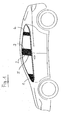
- FIG. 1 shown motor vehicle has a plurality of panels, namely a mirror panel 1 in the rearview mirror, a rear panel 2 of the front door, a front panel 3 of the back door and a rear panel 4 of the back door.
- a display element 5 for displaying information is present in the aperture 2 in the aperture 2.
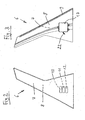
- FIGS. 2 and 3 show a further panel 6 for a motor vehicle in a view from the outside and inside.
- the diaphragm 6 is produced in a two-component injection molding process.
- the first component 7 consists of scratch-resistant PMMA. It is complete, ie semitransparent throughout its range.
- the first component 7 has a shiny, continuous, predominantly smooth surface without cutouts.
- the second component 8 is made of ABS. It has a black color. It lies behind the visible surface forming the first component 7. On the second component 8 is a bar 9 for mounting the panel 6 is provided on the motor vehicle, namely molded.
- the second component 8 has three recesses 10, 11, 12 (see Fig. 2 ), each having a rectangular, rounded shape and which are flush and spaced from each other.
- Fig. 3 the recesses 10, 11, 12 of a housing 13 which is fixed to the second component 8, covered.
- Fig. 4 shows the display elements 14, 15, 16, which are located in the recesses 10, 11, 12, in an enlarged view.
- the display elements 13, 14, 15 form a charge control indicator for a motor vehicle with battery drive.
- the display element 14 is an illuminated display element in green color with the inscription "Full". It is located in the recess 10 and indicates the full state of charge of the battery.
- the display element 15 is an illuminated display element in yellow color with the inscription "Medium”. It is located in the recess 11 and indicates a medium state of charge of the battery.
- the display element 16 is an illuminated display element in red color with the inscription "Empty”. It is located in the recess 12 and shows an insufficient state of charge of the battery.
- the first component 7 is semitransparent in such a way that the display elements 13, 14, 15 are visible through the first component 7 in the illuminated state.
- FIGS. 5 and 6 show the aperture 6 in one of Fig. 3 corresponding representation from the inside.
- the second component 8 has fastening elements for the housing 13.
- the fastening elements are formed by a circumferential frame 17, a first hook 18 and two second hooks 19.
- the fastening elements 17, 18, 19 are integrally formed on the second component 8. They protrude out of the plane of the second component 8.
- the recesses 10, 11, 12 in the second component 8 are within the peripheral frame 17. In the region of the recesses 10, 11, 12 is in the Fig. 6 the first component 7 visible from the rear. The border of the recesses 10, 11, 12 located within the peripheral frame 17 is formed by the second component 8.
- the recesses 10, 11, 12 can be covered by the housing 13.
- the display elements 14, 15, 16 are provided in the housing 13.
- the housing 13 engages over the circumferential edge 17. It is hooked by its first hook 20 with the first hook 18 of the second component 8 and by its second hook 21 with the second hook 19 of the second component 8, as in Fig. 5 shown.
- the power supply of the display elements 14, 15, 16 is effected by an electric cable 22.
- Fig. 8 shows the housing 13 from the inside. Its circumferential groove 23 engages over the peripheral edge 17 of the second component 8 in the mounted state.
- intermediate walls 24, 25 are provided which separate three chambers 27, 28, 29 from each other with the encircling housing wall 26.
- a light emitting diode 30 is provided, which illuminates the respective chamber 27, 28, 29.
- the display element 14 is located in the chamber 27. It is illuminated by the light-emitting diode 30 of the chamber 27.
- the display element 15 is located in the chamber 28 and is illuminated by the LED 30.
- the display element 16 is located in the chamber 29 and is illuminated by the LED 30.
- the display elements 14, 15, 16 completely fill the recesses 10, 11, 12 in the second component 8.
- the display element 16 is omitted; in its place, the recess 12 can be seen.
- a circumferential seal 31 is provided, through which the housing 13 is sealed.
- the circumferential seal 31 can be realized by a sealing bead, in particular by butyl or adhesive.
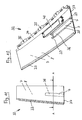
- FIGS. 10 and 11 show a further embodiment of a diaphragm 32, which is substantially that of EP 1 695 808 A1 corresponds to which reference is made.
- the aperture 32 is made in a two-component injection molding process.
- the second component 8 has a fastening strip 33 and a fastening profile 34, which is provided with fastening holes 35 and further mechanical fastening elements.
- the second component 8 also has a recess 36 which is substantially rectangular and extends in the longitudinal direction of the aperture 32. The recess 36 extends to the edge 37 of the aperture 32nd
- the fastening elements of the diaphragm 32 are formed by a U-shaped frame 38 and lugs 39 for fastening screws or rivets, by means of which the housing 40 can be fastened to the diaphragm 32, namely to its second component 8.
- the fastening elements 38, 39 are integrally formed on the second component 8. They are produced in the manufacture of the panel together with the second component 8 in a multi-component process, in particular a 2-component process.
- FIGS. 12 and 13 show a modification of the aperture 32 of the 10 and 11 in which corresponding parts are given the same reference numerals and will not be described again.
- the recess 36 In contrast to the aperture 32 after 10 and 11 enough for the aperture FIGS. 12 and 13 the recess 36 not to the edge 37 of the aperture 32.
- the recess 36 ends in front of this edge 37.
- the recess 36 is surrounded by the base of the second component 8 on all sides.
- Fig. 14 and 15 show a section along the line AA in Fig. 11 ,
- the housing 40 is secured by screws or rivets 41 to the lugs 39 of the second component 8 attached.
- the peripheral edge 42 of the housing 40 encloses the U-shaped frame 38 of the second component 8.
- the housing 40 is sealed by a seal 43 which is located between the peripheral edge 42 and the U-shaped frame 38.
- a keypad 44 of an access system is arranged in the housing 40.
- the keypad 44 has display elements and input elements.
- the light emanating from the display elements penetrates the first component 7 and makes these display elements visible in this way.
- the input elements can be actuated through the first component 7, in particular by finger pressure.
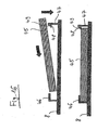
- Fig. 16 shows another embodiment of a keypad 45 having a light unit. There is no housing here.
- the keypad 45 is first slid obliquely under the L-shaped holder 46, as shown in the upper figure, and then pressed over the inclined surface 49 of the barb 48, wherein the flexible retaining lug 47 to the outside, ie away from the keyboard 45, elastic deformed.
- one or more recesses are present in the second component 8, which in Fig. 16 are not shown.
- the invention provides a vehicle trim made of plastic with an integrated information window.
- information can be visually displayed. This may in particular be the following information: Charge control in cars with battery operation; Parking time display for displaying the digital parking ticket (green / red); Keypad for entering an access code to the vehicle; Fingerprint for access authorization in the vehicle; Status display in a taxi (occupied / free); logos and logos (GTI, Ghia etc.); Display surface over the entire surface as a design element; Flashing function; Display of the vehicle condition (opened / closed), in particular when leaving and / or when approaching the driver / owner; Display of the vehicle position for other road users, in particular by a reflection film, especially in poor visibility and / or at night.
- the second component may form a functional layer which is partially recessed to let information show through.
- the first component forms a decorative surface or top surface.
- the diaphragm including its components is a molded part, which is preferably produced by injection molding.
- the aperture is intended for the vehicle exterior.
- It is located on one of the pillars of the vehicle (A-pillar, B-pillar, C-pillar) and / or on a vehicle door.
- Fastening elements clips, screw domes, welded webs, etc.
- Fastening elements for fastening the display elements or input elements or a lighting unit can be formed directly on the panel.
- the display elements and / or input elements are visible only when activated.
- the display elements and / or input elements can also be permanently activated. They can be designed as light-emitting elements.
- a charging current control can be integrated in (C-pillar) capping.
- the customer or driver can also receive feedback on the state of charge in an electric vehicle.
- the control can be done via a simple LED or over several, for example three different colors. It is also possible to display the remaining range in kilometers as a number or the remaining time of battery usage.
- Reflectors are used in road traffic to increase traffic safety. They are usually integrated directly in the headlamps or attached to the bumpers.
- the inventive Solution with a transparent or semitransparent cover layer allows easy integration of the reflectors into a panel without disturbing them.
- reflectors can be positioned in the lateral areas of the vehicle, whereby the traffic safety can be additionally increased.
Landscapes
- Engineering & Computer Science (AREA)
- Mechanical Engineering (AREA)
- Chemical & Material Sciences (AREA)
- Combustion & Propulsion (AREA)
- Transportation (AREA)
- Human Computer Interaction (AREA)
- Vehicle Waterproofing, Decoration, And Sanitation Devices (AREA)
- Lighting Device Outwards From Vehicle And Optical Signal (AREA)
- Illuminated Signs And Luminous Advertising (AREA)
- Arrangements Of Lighting Devices For Vehicle Interiors, Mounting And Supporting Thereof, Circuits Therefore (AREA)
- Instrument Panels (AREA)
- Fittings On The Vehicle Exterior For Carrying Loads, And Devices For Holding Or Mounting Articles (AREA)
- Injection Moulding Of Plastics Or The Like (AREA)
Description
- Die Erfindung betrifft eine Blende oder ein sonstiges Zierteil aus Kunststoff für ein Fahrzeug, insbesondere für ein Kraftfahrzeug, mit einer ersten Komponente aus Kunststoff und mit einer zweiten Komponente aus Kunststoff.
- Eine derartige Blende ist aus der
EP 1 695 808 A1 bekannt. Die vorbekannte Blende umfaßt eine erste Komponente aus Kunststoff, nämlich ein Deckteil aus einem thermoplastischen Kunststoff, und eine zweite Komponente aus Kunststoff, nämlich ein Trägerteil aus einem thermoplastischen Kunststoff. Die erste Komponente ist an einer Sichtfläche der Blende vorgesehen. Sie übernimmt eine dekorative Funktion. Die zweite Komponente übernimmt mechanische Funktionen, insbesondere eine Befestigungsfunktion. Die Blende ist in einem Mehrkomponenten-Spritzgußverfahren, insbesondere in einem Zweikomponenten-Spritzgußverfahren (2-K-Verfahren) hergestellt. - Aus der
US 2006/176710 A1 ist eine Blende aus Kunststoff für ein Fahrzeug nach dem Oberbegriff des Anspruchs 1 bekannt. - Die
US 2006/114685 A1 offenbart eine Anordnung, bei der das Licht einer Lichtquelle von einem Reflektor auf ein Bildelement mit undurchsichtigen und durchsichtigen Teilen zurückgeworfen wird. - Aus der
DE 203 13 996 U1 ist ein Verkleidungselement bekannt, das einen kreisförmigen Durchbruch aufweist, in den ein Leuchtelement eingesetzt ist. - Die
DE 100 58 527 A1 offenbart eine Abdeckung für ein Fahrzeug, die durch eine Ultraschallschweißverbindung mit einer Oberfläche verbunden werden kann. - Aufgabe der Erfindung ist es, eine verbesserte Blende der eingangs angegebenen Art vorzuschlagen.
- Erfindungsgemäß wird diese Aufgabe durch die Merkmale des Anspruchs 1 gelöst. Die erfindungsgemäße Blende aus Kunststoff für den Außenbereich eines Fahrzeugs für eine der Säulen des Fahrzeugs und/oder für eine Fahrzeugtüre umfasst eine erste Komponente aus Kunststoff, die eine Dekorationsfläche oder Deckfläche bildet und die zumindest teilweise transparent oder semitransparent ist, sowie eine zweite Komponente aus Kunststoff, die hinter der ersten Komponente liegt. Die zweite Komponente weist eine oder mehrere Aussparungen für ein Tastenfeld und/oder für einen Sensor auf, wobei das Tastenfeld, das Anzeigeelemente aufweist, und/oder der Sensor in der oder den Aussparungen angeordnet ist bzw. sind. Auf diese Weise ist es möglich, die Blende zur Anzeige von Informationen zu nutzen. Ferner kann die Blende zur Eingabe von Informationen genutzt werden. Es können auch mehrere Anzeigeelemente und/oder Eingabeelemente vorhanden sein.
- Erfindungsgemäß ist die erste Komponente zumindest teilweise transparent oder semitransparent. In diesem Fall erstreckt sich der transparente oder semitransparente Bereich der ersten Komponente über einen Teilbereich dieser ersten Komponente. Die erste Komponente kann allerdings auch vollständig transparent oder semitransparent sein. In diesem Fall ist der gesamte Bereich der ersten Komponente transparent oder semitransparent. In beiden Fällen erstreckt sich der transparente oder semitransparente Bereich der ersten Komponente vollständig oder teilweise über die Aussparung oder die Aussparungen in der zweiten Komponente.
- Die erste Komponente liegt vorzugsweise an einer Außenseite der Blende. Sie kann von einer oder mehreren weiteren Schichten abgedeckt sein, insbesondere von einem Überzug, wobei diese weitere Schicht oder weiteren Schichten oder der Überzug vollständig oder teilweise transparent oder semitransparent sind. Vorzugsweise bildet die erste Komponente eine Sichtfläche an dem Fahrzeug bzw. Kraftfahrzeug, vorzugsweise an der Außenseite, möglicherweise allerdings auch an der Innenseite, des Fahrzeugs oder Kraftfahrzeugs.
- Es ist möglich, daß die Blende weitere Komponenten und/oder Schichten und/oder Bestandteile aufweist. Erfindungsgemäß ist die Blende in einem Mehrkomponenten-Spritzgußverfahren hergestellt, insbesondere in einem Zweikomponenten-Spritz-gußverfahren (2-K-Verfahren) oder in einem Dreikomponenten-Spritzgußverfahren (3-K-Verfahren).
- Das Tastenfeld und/oder der Sensor sind selbstleuchtend oder beleuchtbar. Das Tastenfeld und/oder der Sensor können durch ein Beleuchtungsmittel beleuchtbar sein. Als Beleuchtungsmittel geeignet sind insbesondere LEDs, farbregelbare Folien (beispielsweise eine Dreischicht-RGB-Folie) oder ein Elektrolumineszenz-Leuchtelement. Sowohl bei selbstleuchtenden Anzeigeelementen/Eingabeelementen als auch bei beleuchteten Anzeigeelementen/Eingabeelementen können die Leuchtfarbe und/oder die Leuchtintensität veränderbar sein.
- Vorteilhafte Weiterbildungen sind in den Unteransprüchen beschrieben.
- Die erste Komponente besteht vorzugsweise aus einem thermoplastischen Kunststoff. Besonders geeignet sind PMMA oder PC oder artverwandte Kunststoffe. Die erste Komponente kann insbesondere aus kratzfestem PMMA oder einem sonstigen kratzfesten Kunststoff bzw. thermoplastischen Kunststoff bestehen.
- Vorteilhaft ist es, wenn die erste Komponente eine glänzende, durchgehende, vorwiegend glatte Oberfläche aufweist. Stattdessen oder zusätzlich kann die erste Komponente Erhebungen aufweisen, insbesondere Erhebungen in Form eines Schriftzuges oder Logos.
- Nach einer weiteren vorteilhaften Weiterbildung besteht die zweite Komponente aus einem thermoplastischen Kunststoff. Besonders geeignet sind ABS, ABS/PC oder ASA oder artverwandte Kunststoffe.
- Eine weitere vorteilhafte Weiterbildung ist dadurch gekennzeichnet, daß an der zweiten Komponente eines oder mehrere Befestigungselemente zur Befestigung des Tastenfelds und/oder des Sensors vorgesehen sind. Das Tastenfeld und/oder der Sensor können unmittelbar oder mittelbar an dem oder den Befestigungselementen befestigt sein. Vorteilhaft ist es, wenn das oder die Befestigungselemente an der zweiten Komponente angeformt sind.
- Nach einer weiteren vorteilhaften Weiterbildung ist an der zweiten Komponente ein Gehäuse für das Tastenfeld und/oder für den Sensor befestigbar oder befestigt. Das Gehäuse ist vorzugsweise abdichtbar oder abgedichtet. Besonders vorteilhaft ist es, wenn das Gehäuse an einem oder mehreren Befestigungselementen an der zweiten Komponente befestigbar oder befestigt ist.
- Das oder die Anzeigeelemente und/oder das oder die Eingabeelemente und/oder das oder die Beleuchtungsmittel für das oder die Anzeigeelemente und/oder das oder die Eingabeelemente können durch Sensoren und/oder Schalter aktivierbar und/oder veränderbar sein.
- Durch das Anzeigeelement können insbesondere
- der Ladezustand eines Fahrzeugs mit Batterieantrieb
- und/oder eine Grafik, ein Schriftzug und/oder ein Logo
- und/oder ein Blinker
- und/oder eine Verriegelungsinformation
- und/oder ein Reflektor
- und/oder eine Parkzeitinformation
- und/oder eine Taxiinformation
- Erfindungsgemäß ist vorgesehen, dass das Eingabeelement ein Tastenfeld und/oder einen oder mehrere Sensoren, insbesondere einen Fingerprint-Sensor und/oder einen Sensor für ein Keyless-Go-System, umfaßt.
- Die Erfindung betrifft ferner ein Fahrzeug, insbesondere ein Kraftfahrzeug, das durch eine oder mehrere erfindungsgemäße Blenden oder sonstige Zierteile gekennzeichnet ist.
- Ausführungsbeispiele der Erfindung werden nachstehend anhand der beigefügten Zeichnung im einzelnen erläutert. In der Zeichnung zeigt
- Fig. 1
- ein Kraftfahrzeug mit erfindungsgemäßen Blenden in einer Seitenansicht,
- Fig. 2
- eine Blende mit einer Ladekontrollanzeige für ein Kraftfahrzeug mit Batterieantrieb in einer Ansicht von außen,
- Fig. 3
- die Blende gemäß
Fig. 2 in einer Ansicht von innen, - Fig. 4
- die
Fig. 2 mit einer vergrößerten Ausschnittdarstellung, - Fig. 5
- eine vergrößerte Teilansicht der
Fig. 3 , - Fig. 6
- den Gegenstand der
Fig. 5 bei abgenommenem Gehäuse, - Fig. 7
- eine verkleinerte Darstellung der
Fig. 3 einschließlich einer Schnittlinie IX-IX, - Fig. 8
- das in
Fig. 3 ,5 und7 gezeigte Gehäuse in einer Ansicht von unten, - Fig. 9
- einen Schnitt längs der Linie IX-IX in
Fig. 7 , - Fig. 10
- eine weitere Ausführungsform einer Blende mit einem Zugangssystem in einer perspektivischen Darstellung,
- Fig. 11
- die Blende gemäß
Fig. 10 in einer Ansicht von außen, - Fig. 12
- eine Abwandlung der Blende gemäß
Fig. 10 und 11 in einer perspektivischen Darstellung, - Fig. 13
- die Blende gemäß
Fig. 12 in einer Ansicht von außen, - Fig. 14
- einen Schnitt längs der Linie A-A in
Fig. 11 , - Fig. 15
- eine vergrößerte Darstellung eines Teils der
Fig. 14 und - Fig. 16
- ein weiteres Ausführungsbeispiel für eine Blende mit einem Tastenfeld zur Eingabe eines Zugangscodes eines Kraftfahrzeugs in einem Längsschnitt.
- Das in
Fig. 1 gezeigte Kraftfahrzeug weist mehrere Blenden auf, nämlich eine Spiegelblende 1 im Bereich des Rückspiegels, eine hintere Blende 2 der Vordertür, eine vordere Blende 3 der Hintertür und eine hintere Blende 4 der Hintertür. In der Blende 2 ist ein Anzeigeelement 5 zur Anzeige von Informationen vorhanden. -
Fig. 2 und 3 zeigen eine weitere Blende 6 für ein Kraftfahrzeug in einer Ansicht von außen und innen. Die Blende 6 ist in einem Zweikomponenten-Spritzgußverfahren hergestellt. Die erste Komponente 7 besteht aus kratzfestem PMMA. Sie ist vollständig, also in ihrem gesamten Bereich semitransparent. Die erste Komponente 7 weist eine glänzende, durchgehende, vorwiegend glatte Oberfläche ohne Ausschnitte auf. - Die zweite Komponente 8 ist aus ABS hergestellt. Sie weist eine schwarze Farbe auf. Sie liegt hinter der die Sichtfläche bildenden ersten Komponente 7. An der zweiten Komponente 8 ist eine Leiste 9 zur Befestigung der Blende 6 an dem Kraftfahrzeug vorgesehen, nämlich angeformt.
- Die zweite Komponente 8 weist drei Aussparungen 10, 11, 12 auf (siehe
Fig. 2 ), die jeweils eine rechteckige, abgerundete Form haben und die bündig und im Abstand voneinander untereinander angeordnet sind. InFig. 3 sind die Aussparungen 10, 11, 12 von einem Gehäuse 13, das an der zweiten Komponente 8 befestigt ist, abgedeckt. -
Fig. 4 zeigt die Anzeigeelemente 14, 15, 16, die sich in den Aussparungen 10, 11, 12 befinden, in einer vergrößerten Darstellung. Die Anzeigeelemente 13, 14, 15 bilden eine Ladekontrollanzeige für ein Kraftfahrzeug mit Batterieantrieb. Das Anzeigeelement 14 ist ein beleuchtetes Anzeigeelement in grüner Farbe mit der Aufschrift "Full". Es befindet sich in der Aussparung 10 und zeigt den vollen Ladezustand der Batterie an. Das Anzeigeelement 15 ist ein beleuchtetes Anzeigeelement in gelber Farbe mit der Aufschrift "Medium". Es befindet sich in der Aussparung 11 und zeigt einen mittleren Ladezustand der Batterie an. Das Anzeigeelement 16 ist ein beleuchtetes Anzeigeelement in roter Farbe mit der Aufschrift "Empty". Es befindet sich in der Aussparung 12 und zeigt einen ungenügenden Ladezustand der Batterie. Die erste Komponente 7 ist derart semitransparent, daß die Anzeigeelemente 13, 14, 15 im beleuchteten Zustand durch die erste Komponente 7 hindurch sichtbar sind. -
Fig. 5 und 6 zeigen die Blende 6 in einer derFig. 3 entsprechenden Darstellung von innen. Die zweite Komponente 8 weist Befestigungselemente für das Gehäuse 13 auf. Die Befestigungselemente werden von einem umlaufenden Rahmen 17, einem ersten Haken 18 und zwei zweiten Haken 19 gebildet. Die Befestigungselemente 17, 18, 19 sind an der zweiten Komponente 8 angeformt. Sie ragen aus der Ebene der zweiten Komponente 8 heraus. - Die Aussparungen 10, 11, 12 in der zweiten Komponente 8 liegen innerhalb des umlaufenden Rahmens 17. Im Bereich der Aussparungen 10, 11, 12 ist in der
Fig. 6 die erste Komponente 7 von hinten sichtbar. Die innerhalb des umlaufenden Rahmens 17 befindliche Umrandung der Aussparungen 10, 11, 12 wird von der zweiten Komponente 8 gebildet. - Die Aussparungen 10, 11, 12 können von dem Gehäuse 13 überdeckt werden. In dem Gehäuse 13 sind die Anzeigeelemente 14, 15, 16 vorgesehen. Das Gehäuse 13 übergreift den umlaufenden Rand 17. Es wird durch seinen ersten Haken 20 mit dem ersten Haken 18 der zweiten Komponente 8 und durch seine zweiten Haken 21 mit den zweiten Haken 19 der zweiten Komponente 8 verhakt, wie in
Fig. 5 gezeigt. Die Stromversorgung der Anzeigeelemente 14, 15, 16 erfolgt durch ein Elektrokabel 22. -
Fig. 8 zeigt das Gehäuse 13 von innen. Seine umlaufende Nut 23 übergreift im montierten Zustand den umlaufenden Rand 17 der zweiten Komponente 8. In dem Gehäuse 13 sind Zwischenwände 24, 25 vorgesehen, die mit der umlaufenden Gehäusewand 26 drei Kammern 27, 28, 29 voneinander abtrennen. In jeder Kammer 27, 28, 29 ist eine Leuchtdiode 30 vorgesehen, die die jeweilige Kammer 27, 28, 29 beleuchtet. - Wie aus
Fig. 9 ersichtlich liegt das Anzeigeelement 14 in der Kammer 27. Es wird von der Leuchtdiode 30 der Kammer 27 beleuchtet. Das Anzeigeelement 15 liegt in der Kammer 28 und wird von deren Leuchtdiode 30 beleuchtet. In entsprechender Weise liegt das Anzeigeelement 16 in der Kammer 29 und wird von deren Leuchtdiode 30 beleuchtet. Die Anzeigeelemente 14, 15, 16 füllen die Aussparungen 10, 11, 12 in der zweiten Komponente 8 jeweils vollständig aus. In der vergrößerten Teildarstellung vonFig. 9 ist das Anzeigeelement 16 weggelassen; an seiner Stelle ist die Aussparung 12 zu sehen. - Zwischen dem Grund der umlaufenden Nut 23 der Gehäusewand 26 und der oberen Endfläche des umlaufenden Rahmens 17 der zweiten Komponente 8 ist eine umlaufende Dichtung 31 vorgesehen, durch die das Gehäuse 13 abgedichtet wird. Insbesondere erfolgt eine Abdichtung gegen Spritzwasser, das bei Regen oder beim Waschen des Kraftfahrzeugs hinter die Blende 6 gelangen kann. Die umlaufende Dichtung 31 kann durch eine Dichtraupe realisiert werden, insbesondere durch Butyl oder Kleber.
-
Fig. 10 und 11 zeigen eine weitere Ausführungsform einer Blende 32, die im wesentlichen derjenigen derEP 1 695 808 A1 entspricht, auf die Bezug genommen wird. Auch die Blende 32 ist in einem Zweikomponenten-Spritzgußverfahren hergestellt. Die zweite Komponente 8 weist eine Befestigungsleiste 33 und ein Befestigungsprofil 34 auf, das mit Befestigungslöchern 35 und weiteren mechanischen Befestigungselementen versehen ist. Die zweite Komponente 8 weist ferner eine Aussparung 36 auf, die im wesentlichen rechteckig ist und in Längsrichtung der Blende 32 verläuft. Die Aussparung 36 reicht bis zu dem Rand 37 der Blende 32. - Die Befestigungselemente der Blende 32 werden von einem U-förmigen Rahmen 38 und Ansätzen 39 für Befestigungsschrauben oder Niete gebildet, durch die das Gehäuse 40 an der Blende 32, nämlich an dessen zweiter Komponente 8 befestigt werden kann. Die Befestigungselemente 38, 39 sind an die zweite Komponente 8 angeformt. Sie werden bei der Herstellung der Blende zusammen mit der zweiten Komponente 8 in einem Mehrkomponentenverfahren, insbesondere einem 2-K-Verfahren, hergestellt.
-
Fig. 12 und 13 zeigen eine Abwandlung der Blende 32 derFig. 10 und 11 , bei der entsprechende Teile mit denselben Bezugszeichen versehen sind und nicht erneut beschrieben werden. Im Unterschied zur Blende 32 nachFig. 10 und 11 reicht bei der Blende nachFig. 12 und 13 die Aussparung 36 nicht bis zum Rand 37 der Blende 32. Hier endet die Aussparung 36 vor diesem Rand 37. Die Aussparung 36 wird von der Grundfläche der zweiten Komponente 8 allseits umschlossen. -
Fig. 14 und15 zeigen einen Schnitt längs der Linie A-A inFig. 11 . Das Gehäuse 40 ist durch Schrauben oder Niete 41 an den Ansätzen 39 der zweiten Komponente 8 befestigt. Der umlaufende Rand 42 des Gehäuses 40 umschließt den U-förmigen Rahmen 38 der zweiten Komponente 8. Das Gehäuse 40 ist durch eine Dichtung 43 abgedichtet, die sich zwischen dem umlaufenden Rand 42 und dem U-förmigen Rahmen 38 befindet. - In dem Gehäuse 40 ist ein Tastenfeld 44 eines Zugangssystems angeordnet. Das Tastenfeld 44 weist Anzeigeelemente und Eingabeelemente auf. Das Licht, das von den Anzeigeelementen ausgeht, durchdringt die erste Komponente 7 und macht diese Anzeigeelemente auf diese Weise sichtbar. Die Eingabeelemente können durch die erste Komponente 7 hindurch betätigt werden, insbesondere durch Fingerdruck.
-
Fig. 16 zeigt eine andere Ausführungsform eines Tastenfeld 45, das eine Leuchteinheit aufweist. Hier ist kein Gehäuse vorhanden. An der zweiten Komponente 8 sind ein L-förmiger Halter 46 und ein Halteansatz 47 mit einem Widerhaken 48, der eine schräge Einführfläche 49 aufweist, angeformt. Das Tastenfeld 45 wird zunächst schräg unter den L-förmigen Halter 46 eingeschoben, wie in der oberen Abbildung gezeigt, und anschließend über die Schrägfläche 49 des Widerhakens 48 eingedrückt, wobei sich der flexible Halteansatz 47 nach außen, also von dem Tastenfeld 45 weg, elastisch verformt. Im Bereich des Tastenfelds 45 sind in der zweiten Komponente 8 eine oder mehrere Aussparungen vorhanden, die inFig. 16 nicht dargestellt sind. - Durch die Erfindung wird eine Fahrzeugblende aus Kunststoff mit einem integrierten Informationsfenster geschaffen. In dem transparenten oder semitransparenten Fenster können Informationen optisch angezeigt werden. Dabei kann es sich insbesondere um folgende Informationen handeln: Ladekontrolle bei Autos mit Batteriebetrieb; Parkzeitanzeige zur Anzeige des gelösten digitalen Parkscheins (grün/rot); Tastenfeld zur Eingabe eines Zugangscodes zum Fahrzeug; Fingerprint zur Zugangsberechtigung in das Fahrzeug; Zustandsanzeige bei einem Taxi (besetzt/frei); Schriftzüge und Logos (GTI, Ghia etc.); Anzeigefläche vollflächig als Designelement; Blinkfunktion; Anzeige des Fahrzeugzustandes (geöffnet/geschlossen), insbesondere beim Verlassen und/oder beim Annähern des Fahrers/Besitzers; Anzeige der Fahrzeugposition für andere Verkehrsteilnehmer, insbesondere durch eine Reflektionsfolie, insbesondere bei schlechter Sicht und/oder nachts.
- Bei der Erfindung kann die zweite Komponente eine Funktionsschicht bilden, die teilweise ausgespart ist, um Informationen durchscheinen zu lassen. Die erste Komponente eine Dekorationsfläche oder Deckfläche bildet.
- Sie kann Erhebungen in Form eines Logos oder eines Schriftzuges aufweisen. Diese erhobenen Konturen können von hinten beleuchtet werden. Die Blende einschließlich ihrer Komponenten ist ein Formteil, welches vorzugsweise im Spritzgußverfahren hergestellt ist. Die Blende ist für den Fahrzeugaußenbereich vorgesehen.
- Sie ist auf einer der Säulen des Fahrzeugs (A-Säule, B-Säule, C-Säule) und/oder auf einer Fahrzeugtür zu befinden.
- An der Blende können Befestigungselemente (Clipse, Schraubdome, Schweißstege etc.) zur Befestigung der Anzeigelemente oder Eingabeelemente oder einer Leuchteinheit direkt angeformt sein.
- Es ist möglich, daß die Anzeigeelemente und/oder Eingabeelemente erst bei einer Aktivierung sichtbar werden. Die Anzeigeelemente und/oder Eingabeelemente können allerdings auch ständig aktiviert sein. Sie können als Leuchtelemente ausgestaltet sein.
- Bei einem Auto mit Batterieantrieb kann eine Ladestromkontrolle im (C-pillar) Capping integriert sein. Hierdurch kann der Kunde bzw. Fahrer auch bei einem Elektrofahrzeug ein Feedback über den Ladezustand erhalten. Die Kontrolle kann über eine einfache LED erfolgen oder über mehrere, beispielsweise drei verschiedene Farben. Es ist auch möglich, die verbleibende Reichweite in Kilometer als Zahl oder die noch verbleibende Zeit der Batterienutzung anzuzeigen.
- Durch die Erfindung kann eine Reflektionsfolie realisiert werden. Reflektoren dienen im Straßenverkehr zur Erhöhung der Verkehrssicherheit. Sie sind in der Regel direkt in den Scheinwerfern integriert oder an den Stoßfängern befestigt. Die erfindungsgemäße Lösung mit transparenter oder semitransparenter Deckschicht ermöglicht die einfache Integration der Reflektoren in eine Blende, ohne daß diese störend wirken. Insbesondere können Reflektoren in den seitlichen Bereichen des Fahrzeugs positioniert werden, wodurch die Verkehrssicherheit zusätzlich erhöht werden kann.
Claims (11)
- Blende aus Kunststoff für den Außenbereich eines Fahrzeugs für eine der Säulen des Fahrzeugs und/oder für eine Fahrzeugtüre
mit einer ersten Komponente (7) aus Kunststoff, die eine Dekorationsfläche oder Deckfläche bildet und die zumindest teilweise transparent oder semitransparent ist,
und mit einer zweiten Komponente (8) aus Kunststoff, die hinter der ersten Komponente (7) liegt,
dadurch gekennzeichnet,
dass die zweite Komponente (8) eine oder mehrere Aussparungen (10, 11, 12; 36) für ein Tastenfeld (44, 55) und/oder für einen Sensor aufweist, wobei das Tastenfeld, das Anzeigeelemente aufweist, und/oder der Sensor in der oder den Aussparungen angeordnet ist bzw. sind,
wobei die Blende in einem Mehrkomponenten-Spritzgussverfahren hergestellt ist,
und wobei das Tastenfeld und/oder der Sensor selbstleuchtend oder beleuchtbar ist oder sind. - Blende nach Anspruch 1, dadurch gekennzeichnet, dass die erste Komponente (7) aus einem thermoplastischen Kunststoff, vorzugsweise aus PMMA, besteht.
- Blende nach Anspruch 1 oder 2, dadurch gekennzeichnet, dass die erste Komponente (7) eine glänzende, durchgehende, vorwiegend glatte Oberfläche aufweist.
- Blende nach einem der vorhergehenden Ansprüche, dadurch gekennzeichnet, dass die zweite Komponente (8) aus einem thermoplastischen Kunststoff, vorzugsweise aus ABS, besteht.
- Blende nach einem der vorhergehenden Ansprüche, dadurch gekennzeichnet, dass an der zweiten Komponente (8) eines oder mehrere Befestigungselemente (17, 18, 19; 38, 39; 46, 47, 48, 49) zur Befestigung des Tastenfelds und/oder des Sensors vorgesehen, insbesondere angeformt sind.
- Blende nach einem der vorhergehenden Ansprüche, dadurch gekennzeichnet, dass an der zweiten Komponente (8) ein vorzugsweise abdichtbares oder abgedichtetes (31; 43) Gehäuse (13; 40) für das Tastenfeld und/oder für den Sensor befestigbar oder befestigt (17, 18, 19, 20, 21; 38, 39, 41) ist.
- Blende nach einem der vorhergehenden Ansprüche, dadurch gekennzeichnet, dass die ersten Komponente (7) eine Sichtfläche bildet.
- Blende nach einem der vorhergehenden Ansprüche, dadurch gekennzeichnet, dass das Tastenfeld (44, 55) und/oder der Sensor Eingabeelemente aufweist, die durch die erste Komponente (7) hindurch betätigt werden können.
- Blende nach einem der vorhergehenden Ansprüche, dadurch gekennzeichnet, dass die zweite Komponente (8) eine schwarze Farbe aufweist.
- Blende nach einem der vorhergehenden Ansprüche, dadurch gekennzeichnet, dass die zweite Komponente (8) ein Befestigungsprofil (34) aufweist.
- Fahrzeug, insbesondere Kraftfahrzeug, gekennzeichnet durch eine Blende nach einem der Ansprüche 1 bis 10.
Applications Claiming Priority (2)
| Application Number | Priority Date | Filing Date | Title |
|---|---|---|---|
| DE102009016760 | 2009-04-07 | ||
| PCT/EP2010/002109 WO2010115585A1 (de) | 2009-04-07 | 2010-04-01 | Blende für ein kraftfahrzeug |
Publications (2)
| Publication Number | Publication Date |
|---|---|
| EP2416990A1 EP2416990A1 (de) | 2012-02-15 |
| EP2416990B1 true EP2416990B1 (de) | 2015-09-23 |
Family
ID=42227662
Family Applications (1)
| Application Number | Title | Priority Date | Filing Date |
|---|---|---|---|
| EP10713571.7A Not-in-force EP2416990B1 (de) | 2009-04-07 | 2010-04-01 | Blende für ein kraftfahrzeug |
Country Status (7)
| Country | Link |
|---|---|
| US (4) | US8998282B2 (de) |
| EP (1) | EP2416990B1 (de) |
| KR (1) | KR20120005437A (de) |
| CN (1) | CN102387943B (de) |
| DE (1) | DE102010013700A1 (de) |
| MX (1) | MX2011008589A (de) |
| WO (1) | WO2010115585A1 (de) |
Families Citing this family (38)
| Publication number | Priority date | Publication date | Assignee | Title |
|---|---|---|---|---|
| WO2010081156A1 (en) * | 2009-01-12 | 2010-07-15 | Fisker Automotive, Inc. | Storage compartment with motorized door |
| DE102011111422A1 (de) | 2011-08-23 | 2013-02-28 | Audi Ag | Multifunktionsband für ein Kraftfahrzeug |
| JP6211288B2 (ja) * | 2013-04-05 | 2017-10-11 | アイシン精機株式会社 | 車両用オートドア操作装置、および車両に設けられる装飾部品 |
| FR3011773B1 (fr) * | 2013-10-11 | 2015-10-30 | Renault Sas | Element d'habillage d'un panneau de carrosserie d'un vehicule comprenant une portion transparente ou translucide |
| DE102013018993A1 (de) * | 2013-11-13 | 2015-05-13 | Linden Gmbh | Befestigung eines Schriftzuges/Emblems an einem Kraftfahrzeug |
| DE102014003217A1 (de) * | 2014-03-05 | 2015-09-10 | Audi Ag | Fahrzeug mit einem Elektro-Antriebsmotor und einem elektrischen Energiespeicher |
| CN106458159A (zh) | 2014-04-30 | 2017-02-22 | 德韧营运有限责任公司 | 车辆无钥匙进入系统 |
| DE112015006357T5 (de) * | 2015-03-25 | 2017-12-14 | Kasai Kogyo Co., Ltd. | Fahrzeuginnenkomponente |
| EP3100915B2 (de) | 2015-06-03 | 2022-09-28 | WEIDPLAS GmbH | Bauteil |
| GB2540387A (en) * | 2015-07-15 | 2017-01-18 | Ford Global Tech Llc | Improvements in or relating to electric vehicles |
| CN107710285A (zh) * | 2015-09-30 | 2018-02-16 | 杜拉汽车系统有限公司 | 车辆进入设备及配备有这种设备的车辆装饰部件 |
| EP3150442B1 (de) | 2015-10-02 | 2018-03-14 | Wiegand GmbH | Zierteil für ein fahrzeug |
| CN109074687B (zh) | 2016-05-02 | 2021-10-08 | 德韧营运有限责任公司 | 用于车辆的控制系统和方法 |
| US9802554B1 (en) * | 2016-05-12 | 2017-10-31 | Dura Automotive Holdings U.K. Ltd. | Exterior trim for a motor vehicle |
| DE102017207225A1 (de) * | 2017-04-28 | 2018-10-31 | Volkswagen Aktiengesellschaft | Beleuchtbares Säulenverkleidungsbauteil für eine Kraftfahrzeugkarosserie |
| DE102017112687A1 (de) * | 2017-06-08 | 2018-12-13 | Huf Hülsbeck & Fürst Gmbh & Co. Kg | Vorrichtung mit einem Hauptträger und einem Nebenträger |
| US10322754B2 (en) * | 2017-06-23 | 2019-06-18 | Ford Global Technologies, Llc | Pillar molding with improved scratch resistance |
| US10768358B2 (en) | 2017-08-17 | 2020-09-08 | Dura Operating, Llc | Printed film with mounted light emitting diodes encapsulated in light guide |
| DE102017218516B4 (de) | 2017-10-17 | 2019-04-25 | Volkswagen Aktiengesellschaft | Fahrzeugverkleidung mit Anzeigefunktionalität |
| FR3075745B1 (fr) * | 2017-12-22 | 2022-03-04 | Novares France | Panneau de garniture pour montant exterieur d'un vehicule automobile et procede de fabrication d'un tel panneau de garniture |
| US10434959B2 (en) * | 2018-03-12 | 2019-10-08 | GM Global Technology Operations LLC | Vehicle interior trim assembly including rigid interior trim components connected to one another and a flexible suspension that biases the rigid interior trim components toward one another to limit movement therebetween |
| DE102019100520A1 (de) * | 2019-01-10 | 2020-07-16 | Motherson Innovations Company Limited | Abdeckvorrichtung, Karosseriebauteil und Kraftfahrzeug |
| EP3722065A1 (de) | 2019-04-10 | 2020-10-14 | DURA Automotive Holdings U.K., Ltd. | Kraftfahrzeugzierteil und verfahren zu dessen herstellung |
| US10780820B1 (en) * | 2019-05-23 | 2020-09-22 | Inview Vehicle Trim Corp. | Vehicle door pillar light assembly and method of use thereof |
| CN110723105B (zh) * | 2019-08-26 | 2021-05-18 | 神通科技集团股份有限公司 | 一款带人脸识别和密码输入的b柱饰板 |
| EP4058329B1 (de) * | 2019-11-13 | 2026-04-22 | FREEGLASS GmbH & Co. KG | Fahrzeuganbauteil mit integrierten funktionselementen |
| WO2021110629A1 (fr) * | 2019-12-02 | 2021-06-10 | Hutchinson | Element d'encadrement de vitre pour un vehicule automobile |
| DE102020118044A1 (de) | 2020-07-08 | 2022-01-13 | Preh Gmbh | Eine Anzeigeanordnung mit transparenter Abdeckung und daran verbessert festgelegter Pixelmatrixanzeige sowie zugehöriges Montageverfahren |
| DE102020121482A1 (de) | 2020-08-14 | 2022-02-17 | Dura Automotive Systems Gmbh | Zierleiste |
| DE102020134162A1 (de) | 2020-12-18 | 2022-06-23 | Wkw Engineering Gmbh | Bauteil zum Einbau in ein Kraftfahrzeug |
| JP7348924B2 (ja) * | 2021-03-11 | 2023-09-21 | トヨタ自動車株式会社 | 車両 |
| DE102021107488A1 (de) * | 2021-03-25 | 2022-09-29 | Zumtobel Lighting Gmbh | Abdeckung für eine Leuchte |
| CN113682378A (zh) * | 2021-07-26 | 2021-11-23 | 嘉兴敏胜汽车零部件有限公司 | 一种安装有人脸识别装置的汽车b柱板 |
| US11884238B2 (en) * | 2021-10-21 | 2024-01-30 | Zoox, Inc. | Vehicle door interface interactions |
| JP7392702B2 (ja) | 2021-10-28 | 2023-12-06 | トヨタ自動車株式会社 | 車両側部構造 |
| US12172582B2 (en) | 2022-06-24 | 2024-12-24 | Honda Motor Co., Ltd. | Multiple side component mount on casting for sensor packaging |
| US12637159B2 (en) | 2022-06-24 | 2026-05-26 | Honda Motor Co., Ltd. | Applique attachment on casting |
| CN117681968A (zh) * | 2023-10-10 | 2024-03-12 | 宁波信泰机械有限公司 | 一种汽车智能b柱总成 |
Family Cites Families (32)
| Publication number | Priority date | Publication date | Assignee | Title |
|---|---|---|---|---|
| DE19819557C2 (de) | 1998-04-30 | 2001-05-17 | Brocke Kg I B S | Verfahren zur Herstellung von hinterspritzten Kunststofformteilen |
| DE19859195C2 (de) | 1998-12-21 | 2001-02-22 | Holzindustrie Bruchsal Gmbh | Sichteinbauteil aus Verbundwerkstoff |
| WO2001054888A1 (de) * | 2000-01-25 | 2001-08-02 | Fraunhofer-Gesellschaft zur Förderung der angewandten Forschung e.V. | Verfahren zur herstellung einer dauerhaften verbindung zwischen einem flächigen kunststoffleichtbauteil mit einer qualitätsoberfläche und einem element |
| GB0005312D0 (en) * | 2000-02-28 | 2000-04-26 | Britax Wingard Ltd | Mounting for proximity radar |
| DE10058527A1 (de) | 2000-11-24 | 2002-05-29 | Bosch Gmbh Robert | Abdeckung |
| US6634065B2 (en) * | 2000-12-19 | 2003-10-21 | Decoma Exterior Trim, Inc. | Retainer clip for attaching components to a belt molding |
| US6652128B2 (en) | 2001-01-31 | 2003-11-25 | Textron Automotive Company, Inc. | Backlighting method for an automotive trim panel |
| AT5085U1 (de) | 2001-04-11 | 2002-03-25 | Steyr Daimler Puch Ag | Innenverkleidungsteil eines kraftfahrzeuges mit elektrischen komponenten |
| DE10143883A1 (de) | 2001-09-07 | 2003-03-27 | Magna Eybl Gmbh | Verfahren zur Herstellung eines mehrschichtigen Fahrzeuginnenteils |
| AU2003207854A1 (en) * | 2002-02-06 | 2003-09-02 | Schefenacker Vision Systems Usa Inc. | Center high mounted stop lamp including leds and tir lens |
| DE10240270A1 (de) | 2002-08-31 | 2004-03-18 | Johnson Controls Gmbh | Verkleidungselement für den Innenraum eines Fahrzeugs |
| US20040090767A1 (en) * | 2002-11-12 | 2004-05-13 | Fu-Cheng Hou | Decorative electro-luminescent strip for automobiles |
| DE10341471A1 (de) | 2003-02-04 | 2004-08-19 | Johnson Controls Gmbh | Innenausstattungsteil für ein Fahrzeug und Verfahren zu seiner Herstellung |
| CN2647675Y (zh) * | 2003-03-18 | 2004-10-13 | 陈铿胜 | 汽车装饰用的发光结构 |
| CN2622003Y (zh) * | 2003-03-18 | 2004-06-30 | 陈铿胜 | 汽车装饰用的发光结构 |
| DE20313996U1 (de) | 2003-09-09 | 2003-11-06 | FER Fahrzeugelektrik GmbH, 99817 Eisenach | Verkleidungselement |
| DE10352044A1 (de) | 2003-11-07 | 2005-06-09 | Bayerische Motoren Werke Ag | Eingabeeinrichtung, insbesondere zur Veranlassung von Schaltoperationen im Innenbereich eines Fahrzeuges, sowie hiermit ausgestattetes Interierbauteil |
| DE10359556A1 (de) * | 2003-12-17 | 2005-07-21 | Johnson Controls Gmbh | Befestigungsvorrichtung, insbesondere Klemmvorrichtung, zur Befestigung eines Materials, insbesondere an einem Kraftfahrzeugsitz, und Komponente, insbesondere Kraftfahrzeugsitz |
| US20050244610A1 (en) * | 2004-04-29 | 2005-11-03 | Visteon Global Technologies, Inc. | Injection molding of components for vehicles |
| US7576631B1 (en) * | 2004-10-26 | 2009-08-18 | Adac Plastics, Inc. | Vehicular keyless entry system incorporating textual representation of the vehicle or user of the vehicle |
| US20060114685A1 (en) * | 2004-11-30 | 2006-06-01 | Patrick Seeber | Vehicle-mounted illuminated display |
| DE112005003178T5 (de) * | 2004-12-17 | 2008-02-14 | Stoneridge Control Devices, Inc., Canton | Berührungssensorvorrichtung und Verfahren |
| US7350949B2 (en) * | 2005-02-04 | 2008-04-01 | Adac Plastics, Inc. | Trim component with concealed indicium |
| DE102005036771A1 (de) | 2005-02-24 | 2006-09-07 | Dura Automotive Plettenberg Entwicklungs- Und Vertriebs Gmbh | Zierteil für ein Kraftfahrzeug |
| US20060222841A1 (en) | 2005-03-30 | 2006-10-05 | Kasai Kogyo Co., Ltd. | Automotive interior component and method for manufacturing the same |
| JP4218660B2 (ja) | 2005-05-18 | 2009-02-04 | トヨタ紡織株式会社 | 車両用スイッチ装置 |
| DE102006008385A1 (de) | 2006-02-21 | 2007-08-30 | Benecke-Kaliko Ag | Kunststoffhaut mit Schaltfunktion |
| US20090085368A1 (en) * | 2006-05-09 | 2009-04-02 | Lockheed Martin Corporation | Tactical truck system dashboard |
| US7898531B2 (en) | 2006-12-27 | 2011-03-01 | Visteon Global Technologies, Inc. | System and method of operating an output device in a vehicle |
| US8400265B2 (en) * | 2007-09-17 | 2013-03-19 | Magna International Inc. | Touchless keyless entry keypad integrated with electroluminescence backlight |
| DE102009004985B4 (de) | 2009-01-14 | 2022-11-17 | Nbhx Trim Gmbh | Verkleidungsteil mit Sensor |
| US8405527B2 (en) | 2009-02-27 | 2013-03-26 | Stoneridge Control Devices, Inc. | Touch sensor system with memory |
-
2010
- 2010-04-01 CN CN201080015707.XA patent/CN102387943B/zh not_active Expired - Fee Related
- 2010-04-01 DE DE102010013700A patent/DE102010013700A1/de not_active Withdrawn
- 2010-04-01 KR KR1020117019678A patent/KR20120005437A/ko not_active Withdrawn
- 2010-04-01 EP EP10713571.7A patent/EP2416990B1/de not_active Not-in-force
- 2010-04-01 US US13/263,195 patent/US8998282B2/en active Active
- 2010-04-01 WO PCT/EP2010/002109 patent/WO2010115585A1/de not_active Ceased
- 2010-04-01 MX MX2011008589A patent/MX2011008589A/es active IP Right Grant
-
2015
- 2015-03-03 US US14/636,333 patent/US9533628B2/en not_active Expired - Fee Related
-
2016
- 2016-11-29 US US15/363,465 patent/US10246032B2/en active Active
-
2019
- 2019-01-15 US US16/247,873 patent/US10836329B2/en not_active Expired - Fee Related
Also Published As
| Publication number | Publication date |
|---|---|
| US20150307035A1 (en) | 2015-10-29 |
| US10246032B2 (en) | 2019-04-02 |
| US8998282B2 (en) | 2015-04-07 |
| CN102387943A (zh) | 2012-03-21 |
| WO2010115585A1 (de) | 2010-10-14 |
| US20190143910A1 (en) | 2019-05-16 |
| US20170072871A1 (en) | 2017-03-16 |
| MX2011008589A (es) | 2011-12-16 |
| US9533628B2 (en) | 2017-01-03 |
| US10836329B2 (en) | 2020-11-17 |
| US20120032463A1 (en) | 2012-02-09 |
| EP2416990A1 (de) | 2012-02-15 |
| DE102010013700A1 (de) | 2011-08-04 |
| CN102387943B (zh) | 2015-05-20 |
| KR20120005437A (ko) | 2012-01-16 |
Similar Documents
| Publication | Publication Date | Title |
|---|---|---|
| EP2416990A1 (de) | Blende für ein kraftfahrzeug | |
| EP3046804B1 (de) | Abdeckungseinrichtung, system, karosseriebauteil, karosseriebauteilsystem und fahrzeug | |
| DE102009005558B4 (de) | Kraftfahrzeug mit einer Schalenstruktur mit integrierten Leuchtelementen | |
| EP2684744B1 (de) | Zierteil für kraftfahrzeuge und verfahren zu seiner herstellung | |
| EP2686203B1 (de) | Leuchtvorrichtung mit animiertem lauflicht für ein kraftfahrzeug | |
| DE19524602C2 (de) | Zierverkleidungsteil für einen Innenraum eines Kraftfahrzeugs | |
| DE102008064233B4 (de) | Einstiegsleiste für Kraftfahrzeuge | |
| EP3575153A1 (de) | Hinterleuchtbares bauteil | |
| EP0911218A2 (de) | Fahrzeug mit Elektrolumineszenz-Leuchtband | |
| DE102015205630A1 (de) | Abdeckungseinrichtung, System, Karosseriebauteil, Karosseriebauteilsystem und Fahrzeug | |
| DE102011112835A1 (de) | Beleuchtungsanordnung für einen Kraftwagen | |
| DE202009013886U1 (de) | Außenverkleidungstelle und Dichtungsanordnungen für Fenster, Türen und Dächer sowie Deckel von Fahrzeugen mit reflektierenden oder retroreflektierenden Eigenschaften | |
| DE202020104697U1 (de) | Verkleidungsanordnung für ein Fahrzeug sowie Fahrzeug mit der Verkleidungsanordnung | |
| EP2525138B1 (de) | Kraftfahrzeugleuchte und Verfahren zu deren Herstellung | |
| DE102020205520A1 (de) | Innenverkleidungsteil für ein Kraftfahrzeug | |
| DE102009022667B4 (de) | Fahrzeugschlüssel mit Betätigungselement und Verfahren zur Herstellung desselben | |
| EP4344949B1 (de) | Beleuchtungssystem für ein aussenverkleidungsteil eines kraftfahrzeugs | |
| EP4015187A1 (de) | Durchleuchtbares verkleidungsteil für ein kraftfahrzeug und verfahren zur herstellung eines durchleuchtbaren verkleidungsteils | |
| DE102017207225A1 (de) | Beleuchtbares Säulenverkleidungsbauteil für eine Kraftfahrzeugkarosserie | |
| EP1857350B1 (de) | Fahrzeugdach mit einem zumindest in Teilbereichen in seiner Transparenz veränderten Dachteil aus Kunststoff | |
| EP3299217B1 (de) | Abdeckungseinrichtung, system, karosseriebauteil, karosseriebauteilsystem und fahrzeug | |
| DE102007002024A1 (de) | Anordnung für eine Klappe eines Kraftfahrzeugs | |
| DE10318790B4 (de) | Kraftfahrzeugemblem | |
| DE102015206902A1 (de) | Verfahren zur Herstellung einer Längsträgerverkleidungen sowie Längsträgerverkleidung | |
| EP4660013A1 (de) | Hinterleuchtbares bauteil |
Legal Events
| Date | Code | Title | Description |
|---|---|---|---|
| PUAI | Public reference made under article 153(3) epc to a published international application that has entered the european phase |
Free format text: ORIGINAL CODE: 0009012 |
|
| 17P | Request for examination filed |
Effective date: 20110720 |
|
| AK | Designated contracting states |
Kind code of ref document: A1 Designated state(s): AT BE BG CH CY CZ DE DK EE ES FI FR GB GR HR HU IE IS IT LI LT LU LV MC MK MT NL NO PL PT RO SE SI SK SM TR |
|
| DAX | Request for extension of the european patent (deleted) | ||
| 17Q | First examination report despatched |
Effective date: 20140603 |
|
| GRAP | Despatch of communication of intention to grant a patent |
Free format text: ORIGINAL CODE: EPIDOSNIGR1 |
|
| TPAC | Observations filed by third parties |
Free format text: ORIGINAL CODE: EPIDOSNTIPA |
|
| INTG | Intention to grant announced |
Effective date: 20150626 |
|
| GRAS | Grant fee paid |
Free format text: ORIGINAL CODE: EPIDOSNIGR3 |
|
| GRAA | (expected) grant |
Free format text: ORIGINAL CODE: 0009210 |
|
| AK | Designated contracting states |
Kind code of ref document: B1 Designated state(s): AT BE BG CH CY CZ DE DK EE ES FI FR GB GR HR HU IE IS IT LI LT LU LV MC MK MT NL NO PL PT RO SE SI SK SM TR |
|
| REG | Reference to a national code |
Ref country code: GB Ref legal event code: FG4D Free format text: NOT ENGLISH |
|
| REG | Reference to a national code |
Ref country code: CH Ref legal event code: EP |
|
| REG | Reference to a national code |
Ref country code: AT Ref legal event code: REF Ref document number: 751053 Country of ref document: AT Kind code of ref document: T Effective date: 20151015 |
|
| REG | Reference to a national code |
Ref country code: IE Ref legal event code: FG4D Free format text: LANGUAGE OF EP DOCUMENT: GERMAN |
|
| REG | Reference to a national code |
Ref country code: DE Ref legal event code: R096 Ref document number: 502010010360 Country of ref document: DE |
|
| REG | Reference to a national code |
Ref country code: NL Ref legal event code: MP Effective date: 20150923 |
|
| PG25 | Lapsed in a contracting state [announced via postgrant information from national office to epo] |
Ref country code: LV Free format text: LAPSE BECAUSE OF FAILURE TO SUBMIT A TRANSLATION OF THE DESCRIPTION OR TO PAY THE FEE WITHIN THE PRESCRIBED TIME-LIMIT Effective date: 20150923 Ref country code: GR Free format text: LAPSE BECAUSE OF FAILURE TO SUBMIT A TRANSLATION OF THE DESCRIPTION OR TO PAY THE FEE WITHIN THE PRESCRIBED TIME-LIMIT Effective date: 20151224 Ref country code: LT Free format text: LAPSE BECAUSE OF FAILURE TO SUBMIT A TRANSLATION OF THE DESCRIPTION OR TO PAY THE FEE WITHIN THE PRESCRIBED TIME-LIMIT Effective date: 20150923 Ref country code: FI Free format text: LAPSE BECAUSE OF FAILURE TO SUBMIT A TRANSLATION OF THE DESCRIPTION OR TO PAY THE FEE WITHIN THE PRESCRIBED TIME-LIMIT Effective date: 20150923 Ref country code: NO Free format text: LAPSE BECAUSE OF FAILURE TO SUBMIT A TRANSLATION OF THE DESCRIPTION OR TO PAY THE FEE WITHIN THE PRESCRIBED TIME-LIMIT Effective date: 20151223 |
|
| REG | Reference to a national code |
Ref country code: LT Ref legal event code: MG4D |
|
| PG25 | Lapsed in a contracting state [announced via postgrant information from national office to epo] |
Ref country code: SE Free format text: LAPSE BECAUSE OF FAILURE TO SUBMIT A TRANSLATION OF THE DESCRIPTION OR TO PAY THE FEE WITHIN THE PRESCRIBED TIME-LIMIT Effective date: 20150923 Ref country code: HR Free format text: LAPSE BECAUSE OF FAILURE TO SUBMIT A TRANSLATION OF THE DESCRIPTION OR TO PAY THE FEE WITHIN THE PRESCRIBED TIME-LIMIT Effective date: 20150923 |
|
| PG25 | Lapsed in a contracting state [announced via postgrant information from national office to epo] |
Ref country code: NL Free format text: LAPSE BECAUSE OF FAILURE TO SUBMIT A TRANSLATION OF THE DESCRIPTION OR TO PAY THE FEE WITHIN THE PRESCRIBED TIME-LIMIT Effective date: 20150923 |
|
| REG | Reference to a national code |
Ref country code: FR Ref legal event code: PLFP Year of fee payment: 7 |
|
| PG25 | Lapsed in a contracting state [announced via postgrant information from national office to epo] |
Ref country code: ES Free format text: LAPSE BECAUSE OF FAILURE TO SUBMIT A TRANSLATION OF THE DESCRIPTION OR TO PAY THE FEE WITHIN THE PRESCRIBED TIME-LIMIT Effective date: 20150923 Ref country code: IS Free format text: LAPSE BECAUSE OF FAILURE TO SUBMIT A TRANSLATION OF THE DESCRIPTION OR TO PAY THE FEE WITHIN THE PRESCRIBED TIME-LIMIT Effective date: 20160123 Ref country code: IT Free format text: LAPSE BECAUSE OF FAILURE TO SUBMIT A TRANSLATION OF THE DESCRIPTION OR TO PAY THE FEE WITHIN THE PRESCRIBED TIME-LIMIT Effective date: 20150923 Ref country code: EE Free format text: LAPSE BECAUSE OF FAILURE TO SUBMIT A TRANSLATION OF THE DESCRIPTION OR TO PAY THE FEE WITHIN THE PRESCRIBED TIME-LIMIT Effective date: 20150923 Ref country code: SK Free format text: LAPSE BECAUSE OF FAILURE TO SUBMIT A TRANSLATION OF THE DESCRIPTION OR TO PAY THE FEE WITHIN THE PRESCRIBED TIME-LIMIT Effective date: 20150923 |
|
| PG25 | Lapsed in a contracting state [announced via postgrant information from national office to epo] |
Ref country code: PL Free format text: LAPSE BECAUSE OF FAILURE TO SUBMIT A TRANSLATION OF THE DESCRIPTION OR TO PAY THE FEE WITHIN THE PRESCRIBED TIME-LIMIT Effective date: 20150923 Ref country code: PT Free format text: LAPSE BECAUSE OF FAILURE TO SUBMIT A TRANSLATION OF THE DESCRIPTION OR TO PAY THE FEE WITHIN THE PRESCRIBED TIME-LIMIT Effective date: 20160125 Ref country code: RO Free format text: LAPSE BECAUSE OF FAILURE TO SUBMIT A TRANSLATION OF THE DESCRIPTION OR TO PAY THE FEE WITHIN THE PRESCRIBED TIME-LIMIT Effective date: 20150923 |
|
| REG | Reference to a national code |
Ref country code: DE Ref legal event code: R097 Ref document number: 502010010360 Country of ref document: DE |
|
| PGFP | Annual fee paid to national office [announced via postgrant information from national office to epo] |
Ref country code: CZ Payment date: 20160420 Year of fee payment: 7 |
|
| PLBE | No opposition filed within time limit |
Free format text: ORIGINAL CODE: 0009261 |
|
| STAA | Information on the status of an ep patent application or granted ep patent |
Free format text: STATUS: NO OPPOSITION FILED WITHIN TIME LIMIT |
|
| 26N | No opposition filed |
Effective date: 20160624 |
|
| PG25 | Lapsed in a contracting state [announced via postgrant information from national office to epo] |
Ref country code: DK Free format text: LAPSE BECAUSE OF FAILURE TO SUBMIT A TRANSLATION OF THE DESCRIPTION OR TO PAY THE FEE WITHIN THE PRESCRIBED TIME-LIMIT Effective date: 20150923 Ref country code: BE Free format text: LAPSE BECAUSE OF NON-PAYMENT OF DUE FEES Effective date: 20160430 |
|
| PG25 | Lapsed in a contracting state [announced via postgrant information from national office to epo] |
Ref country code: SI Free format text: LAPSE BECAUSE OF FAILURE TO SUBMIT A TRANSLATION OF THE DESCRIPTION OR TO PAY THE FEE WITHIN THE PRESCRIBED TIME-LIMIT Effective date: 20150923 |
|
| REG | Reference to a national code |
Ref country code: CH Ref legal event code: PL |
|
| PG25 | Lapsed in a contracting state [announced via postgrant information from national office to epo] |
Ref country code: LU Free format text: LAPSE BECAUSE OF FAILURE TO SUBMIT A TRANSLATION OF THE DESCRIPTION OR TO PAY THE FEE WITHIN THE PRESCRIBED TIME-LIMIT Effective date: 20160401 |
|
| REG | Reference to a national code |
Ref country code: DE Ref legal event code: R081 Ref document number: 502010010360 Country of ref document: DE Owner name: PLASMAN EUROPE AB, SE Free format text: FORMER OWNER: DURA AUTOMOTIVE BODY AND GLASS SYSTEMS GMBH, 58840 PLETTENBERG, DE Ref country code: DE Ref legal event code: R082 Ref document number: 502010010360 Country of ref document: DE Representative=s name: LORENZ SEIDLER GOSSEL RECHTSANWAELTE PATENTANW, DE Ref country code: DE Ref legal event code: R081 Ref document number: 502010010360 Country of ref document: DE Owner name: DURA AUTOMOTIVE HOLDINGS U.K., LTD., CASTLE VA, GB Free format text: FORMER OWNER: DURA AUTOMOTIVE BODY AND GLASS SYSTEMS GMBH, 58840 PLETTENBERG, DE |
|
| REG | Reference to a national code |
Ref country code: IE Ref legal event code: MM4A |
|
| PG25 | Lapsed in a contracting state [announced via postgrant information from national office to epo] |
Ref country code: LI Free format text: LAPSE BECAUSE OF NON-PAYMENT OF DUE FEES Effective date: 20160430 Ref country code: CH Free format text: LAPSE BECAUSE OF NON-PAYMENT OF DUE FEES Effective date: 20160430 |
|
| REG | Reference to a national code |
Ref country code: FR Ref legal event code: PLFP Year of fee payment: 8 |
|
| PG25 | Lapsed in a contracting state [announced via postgrant information from national office to epo] |
Ref country code: IE Free format text: LAPSE BECAUSE OF NON-PAYMENT OF DUE FEES Effective date: 20160401 |
|
| REG | Reference to a national code |
Ref country code: AT Ref legal event code: MM01 Ref document number: 751053 Country of ref document: AT Kind code of ref document: T Effective date: 20160401 |
|
| REG | Reference to a national code |
Ref country code: FR Ref legal event code: TP Owner name: DURA AUTOMOTIVE BODY AND GLASS SYSTEMS GMBH, DE Effective date: 20170629 |
|
| REG | Reference to a national code |
Ref country code: GB Ref legal event code: 732E Free format text: REGISTERED BETWEEN 20170727 AND 20170802 |
|
| PG25 | Lapsed in a contracting state [announced via postgrant information from national office to epo] |
Ref country code: AT Free format text: LAPSE BECAUSE OF NON-PAYMENT OF DUE FEES Effective date: 20160401 |
|
| PG25 | Lapsed in a contracting state [announced via postgrant information from national office to epo] |
Ref country code: CZ Free format text: LAPSE BECAUSE OF NON-PAYMENT OF DUE FEES Effective date: 20170401 |
|
| REG | Reference to a national code |
Ref country code: FR Ref legal event code: PLFP Year of fee payment: 9 |
|
| PG25 | Lapsed in a contracting state [announced via postgrant information from national office to epo] |
Ref country code: CY Free format text: LAPSE BECAUSE OF FAILURE TO SUBMIT A TRANSLATION OF THE DESCRIPTION OR TO PAY THE FEE WITHIN THE PRESCRIBED TIME-LIMIT Effective date: 20150923 Ref country code: SM Free format text: LAPSE BECAUSE OF FAILURE TO SUBMIT A TRANSLATION OF THE DESCRIPTION OR TO PAY THE FEE WITHIN THE PRESCRIBED TIME-LIMIT Effective date: 20150923 Ref country code: HU Free format text: LAPSE BECAUSE OF FAILURE TO SUBMIT A TRANSLATION OF THE DESCRIPTION OR TO PAY THE FEE WITHIN THE PRESCRIBED TIME-LIMIT; INVALID AB INITIO Effective date: 20100401 |
|
| PG25 | Lapsed in a contracting state [announced via postgrant information from national office to epo] |
Ref country code: MK Free format text: LAPSE BECAUSE OF FAILURE TO SUBMIT A TRANSLATION OF THE DESCRIPTION OR TO PAY THE FEE WITHIN THE PRESCRIBED TIME-LIMIT Effective date: 20150923 Ref country code: TR Free format text: LAPSE BECAUSE OF FAILURE TO SUBMIT A TRANSLATION OF THE DESCRIPTION OR TO PAY THE FEE WITHIN THE PRESCRIBED TIME-LIMIT Effective date: 20150923 Ref country code: MC Free format text: LAPSE BECAUSE OF FAILURE TO SUBMIT A TRANSLATION OF THE DESCRIPTION OR TO PAY THE FEE WITHIN THE PRESCRIBED TIME-LIMIT Effective date: 20150923 Ref country code: MT Free format text: LAPSE BECAUSE OF FAILURE TO SUBMIT A TRANSLATION OF THE DESCRIPTION OR TO PAY THE FEE WITHIN THE PRESCRIBED TIME-LIMIT Effective date: 20150923 |
|
| PG25 | Lapsed in a contracting state [announced via postgrant information from national office to epo] |
Ref country code: BG Free format text: LAPSE BECAUSE OF FAILURE TO SUBMIT A TRANSLATION OF THE DESCRIPTION OR TO PAY THE FEE WITHIN THE PRESCRIBED TIME-LIMIT Effective date: 20150923 |
|
| REG | Reference to a national code |
Ref country code: DE Ref legal event code: R081 Ref document number: 502010010360 Country of ref document: DE Owner name: PLASMAN EUROPE AB, SE Free format text: FORMER OWNER: DURA AUTOMOTIVE HOLDINGS U.K., LTD., CASTLE VALE, BIRMINGHAM, GB Ref country code: DE Ref legal event code: R082 Ref document number: 502010010360 Country of ref document: DE Representative=s name: BTB IP BUNGARTZ BALTZER PARTNERSCHAFT MBB PATE, DE |
|
| REG | Reference to a national code |
Ref country code: GB Ref legal event code: 732E Free format text: REGISTERED BETWEEN 20220623 AND 20220629 |
|
| PGFP | Annual fee paid to national office [announced via postgrant information from national office to epo] |
Ref country code: FR Payment date: 20230424 Year of fee payment: 14 Ref country code: DE Payment date: 20230418 Year of fee payment: 14 |
|
| PGFP | Annual fee paid to national office [announced via postgrant information from national office to epo] |
Ref country code: GB Payment date: 20230421 Year of fee payment: 14 |
|
| REG | Reference to a national code |
Ref country code: DE Ref legal event code: R119 Ref document number: 502010010360 Country of ref document: DE |
|
| GBPC | Gb: european patent ceased through non-payment of renewal fee |
Effective date: 20240401 |
|
| PG25 | Lapsed in a contracting state [announced via postgrant information from national office to epo] |
Ref country code: DE Free format text: LAPSE BECAUSE OF NON-PAYMENT OF DUE FEES Effective date: 20241105 |
|
| PG25 | Lapsed in a contracting state [announced via postgrant information from national office to epo] |
Ref country code: GB Free format text: LAPSE BECAUSE OF NON-PAYMENT OF DUE FEES Effective date: 20240401 |
|
| PG25 | Lapsed in a contracting state [announced via postgrant information from national office to epo] |
Ref country code: FR Free format text: LAPSE BECAUSE OF NON-PAYMENT OF DUE FEES Effective date: 20240430 |
|
| PG25 | Lapsed in a contracting state [announced via postgrant information from national office to epo] |
Ref country code: GB Free format text: LAPSE BECAUSE OF NON-PAYMENT OF DUE FEES Effective date: 20240401 Ref country code: FR Free format text: LAPSE BECAUSE OF NON-PAYMENT OF DUE FEES Effective date: 20240430 Ref country code: DE Free format text: LAPSE BECAUSE OF NON-PAYMENT OF DUE FEES Effective date: 20241105 |