EP4344949B1 - Beleuchtungssystem für ein aussenverkleidungsteil eines kraftfahrzeugs - Google Patents
Beleuchtungssystem für ein aussenverkleidungsteil eines kraftfahrzeugs Download PDFInfo
- Publication number
- EP4344949B1 EP4344949B1 EP23197622.6A EP23197622A EP4344949B1 EP 4344949 B1 EP4344949 B1 EP 4344949B1 EP 23197622 A EP23197622 A EP 23197622A EP 4344949 B1 EP4344949 B1 EP 4344949B1
- Authority
- EP
- European Patent Office
- Prior art keywords
- configuration region
- light
- lighting system
- housing element
- trim part
- Prior art date
- Legal status (The legal status is an assumption and is not a legal conclusion. Google has not performed a legal analysis and makes no representation as to the accuracy of the status listed.)
- Active
Links
Images
Classifications
-
- B—PERFORMING OPERATIONS; TRANSPORTING
- B60—VEHICLES IN GENERAL
- B60Q—ARRANGEMENT OF SIGNALLING OR LIGHTING DEVICES, THE MOUNTING OR SUPPORTING THEREOF OR CIRCUITS THEREFOR, FOR VEHICLES IN GENERAL
- B60Q1/00—Arrangement of optical signalling or lighting devices, the mounting or supporting thereof or circuits therefor
- B60Q1/26—Arrangement of optical signalling or lighting devices, the mounting or supporting thereof or circuits therefor the devices being primarily intended to indicate the vehicle, or parts thereof, or to give signals, to other traffic
-
- B—PERFORMING OPERATIONS; TRANSPORTING
- B60—VEHICLES IN GENERAL
- B60Q—ARRANGEMENT OF SIGNALLING OR LIGHTING DEVICES, THE MOUNTING OR SUPPORTING THEREOF OR CIRCUITS THEREFOR, FOR VEHICLES IN GENERAL
- B60Q1/00—Arrangement of optical signalling or lighting devices, the mounting or supporting thereof or circuits therefor
- B60Q1/0029—Spatial arrangement
- B60Q1/0035—Spatial arrangement relative to the vehicle
-
- B—PERFORMING OPERATIONS; TRANSPORTING
- B32—LAYERED PRODUCTS
- B32B—LAYERED PRODUCTS, i.e. PRODUCTS BUILT-UP OF STRATA OF FLAT OR NON-FLAT, e.g. CELLULAR OR HONEYCOMB, FORM
- B32B27/00—Layered products comprising a layer of synthetic resin
- B32B27/06—Layered products comprising a layer of synthetic resin as the main or only constituent of a layer, which is next to another layer of the same or of a different material
- B32B27/08—Layered products comprising a layer of synthetic resin as the main or only constituent of a layer, which is next to another layer of the same or of a different material of synthetic resin
-
- B—PERFORMING OPERATIONS; TRANSPORTING
- B32—LAYERED PRODUCTS
- B32B—LAYERED PRODUCTS, i.e. PRODUCTS BUILT-UP OF STRATA OF FLAT OR NON-FLAT, e.g. CELLULAR OR HONEYCOMB, FORM
- B32B27/00—Layered products comprising a layer of synthetic resin
- B32B27/30—Layered products comprising a layer of synthetic resin comprising vinyl (co)polymers; comprising acrylic (co)polymers
- B32B27/308—Layered products comprising a layer of synthetic resin comprising vinyl (co)polymers; comprising acrylic (co)polymers comprising acrylic (co)polymers
-
- B—PERFORMING OPERATIONS; TRANSPORTING
- B32—LAYERED PRODUCTS
- B32B—LAYERED PRODUCTS, i.e. PRODUCTS BUILT-UP OF STRATA OF FLAT OR NON-FLAT, e.g. CELLULAR OR HONEYCOMB, FORM
- B32B27/00—Layered products comprising a layer of synthetic resin
- B32B27/36—Layered products comprising a layer of synthetic resin comprising polyesters
- B32B27/365—Layered products comprising a layer of synthetic resin comprising polyesters comprising polycarbonates
-
- B—PERFORMING OPERATIONS; TRANSPORTING
- B60—VEHICLES IN GENERAL
- B60R—VEHICLES, VEHICLE FITTINGS, OR VEHICLE PARTS, NOT OTHERWISE PROVIDED FOR
- B60R13/00—Elements for body-finishing, identifying, or decorating; Arrangements or adaptations for advertising purposes
- B60R13/005—Manufacturers' emblems, name plates, bonnet ornaments, mascots or the like; Mounting means therefor
-
- B—PERFORMING OPERATIONS; TRANSPORTING
- B60—VEHICLES IN GENERAL
- B60R—VEHICLES, VEHICLE FITTINGS, OR VEHICLE PARTS, NOT OTHERWISE PROVIDED FOR
- B60R13/00—Elements for body-finishing, identifying, or decorating; Arrangements or adaptations for advertising purposes
- B60R13/04—External Ornamental or guard strips; Ornamental inscriptive devices thereon
-
- F—MECHANICAL ENGINEERING; LIGHTING; HEATING; WEAPONS; BLASTING
- F21—LIGHTING
- F21S—NON-PORTABLE LIGHTING DEVICES; SYSTEMS THEREOF; VEHICLE LIGHTING DEVICES SPECIALLY ADAPTED FOR VEHICLE EXTERIORS
- F21S43/00—Signalling devices specially adapted for vehicle exteriors, e.g. brake lamps, direction indicator lights or reversing lights
- F21S43/10—Signalling devices specially adapted for vehicle exteriors, e.g. brake lamps, direction indicator lights or reversing lights characterised by the light source
- F21S43/13—Signalling devices specially adapted for vehicle exteriors, e.g. brake lamps, direction indicator lights or reversing lights characterised by the light source characterised by the type of light source
- F21S43/14—Light emitting diodes [LED]
-
- F—MECHANICAL ENGINEERING; LIGHTING; HEATING; WEAPONS; BLASTING
- F21—LIGHTING
- F21S—NON-PORTABLE LIGHTING DEVICES; SYSTEMS THEREOF; VEHICLE LIGHTING DEVICES SPECIALLY ADAPTED FOR VEHICLE EXTERIORS
- F21S43/00—Signalling devices specially adapted for vehicle exteriors, e.g. brake lamps, direction indicator lights or reversing lights
- F21S43/20—Signalling devices specially adapted for vehicle exteriors, e.g. brake lamps, direction indicator lights or reversing lights characterised by refractors, transparent cover plates, light guides or filters
- F21S43/235—Light guides
- F21S43/236—Light guides characterised by the shape of the light guide
- F21S43/239—Light guides characterised by the shape of the light guide plate-shaped
-
- F—MECHANICAL ENGINEERING; LIGHTING; HEATING; WEAPONS; BLASTING
- F21—LIGHTING
- F21S—NON-PORTABLE LIGHTING DEVICES; SYSTEMS THEREOF; VEHICLE LIGHTING DEVICES SPECIALLY ADAPTED FOR VEHICLE EXTERIORS
- F21S43/00—Signalling devices specially adapted for vehicle exteriors, e.g. brake lamps, direction indicator lights or reversing lights
- F21S43/20—Signalling devices specially adapted for vehicle exteriors, e.g. brake lamps, direction indicator lights or reversing lights characterised by refractors, transparent cover plates, light guides or filters
- F21S43/235—Light guides
- F21S43/242—Light guides characterised by the emission area
- F21S43/245—Light guides characterised by the emission area emitting light from one or more of its major surfaces
-
- F—MECHANICAL ENGINEERING; LIGHTING; HEATING; WEAPONS; BLASTING
- F21—LIGHTING
- F21S—NON-PORTABLE LIGHTING DEVICES; SYSTEMS THEREOF; VEHICLE LIGHTING DEVICES SPECIALLY ADAPTED FOR VEHICLE EXTERIORS
- F21S43/00—Signalling devices specially adapted for vehicle exteriors, e.g. brake lamps, direction indicator lights or reversing lights
- F21S43/20—Signalling devices specially adapted for vehicle exteriors, e.g. brake lamps, direction indicator lights or reversing lights characterised by refractors, transparent cover plates, light guides or filters
- F21S43/235—Light guides
- F21S43/249—Light guides with two or more light sources being coupled into the light guide
-
- F—MECHANICAL ENGINEERING; LIGHTING; HEATING; WEAPONS; BLASTING
- F21—LIGHTING
- F21S—NON-PORTABLE LIGHTING DEVICES; SYSTEMS THEREOF; VEHICLE LIGHTING DEVICES SPECIALLY ADAPTED FOR VEHICLE EXTERIORS
- F21S43/00—Signalling devices specially adapted for vehicle exteriors, e.g. brake lamps, direction indicator lights or reversing lights
- F21S43/20—Signalling devices specially adapted for vehicle exteriors, e.g. brake lamps, direction indicator lights or reversing lights characterised by refractors, transparent cover plates, light guides or filters
- F21S43/26—Refractors, transparent cover plates, light guides or filters not provided in groups F21S43/235 - F21S43/255
-
- G—PHYSICS
- G02—OPTICS
- G02B—OPTICAL ELEMENTS, SYSTEMS OR APPARATUS
- G02B6/00—Light guides; Structural details of arrangements comprising light guides and other optical elements, e.g. couplings
- G02B6/0001—Light guides; Structural details of arrangements comprising light guides and other optical elements, e.g. couplings specially adapted for lighting devices or systems
- G02B6/0011—Light guides; Structural details of arrangements comprising light guides and other optical elements, e.g. couplings specially adapted for lighting devices or systems the light guides being planar or of plate-like form
- G02B6/0033—Means for improving the coupling-out of light from the light guide
- G02B6/0035—Means for improving the coupling-out of light from the light guide provided on the surface of the light guide or in the bulk of it
- G02B6/004—Scattering dots or dot-like elements, e.g. microbeads, scattering particles, nanoparticles
- G02B6/0041—Scattering dots or dot-like elements, e.g. microbeads, scattering particles, nanoparticles provided in the bulk of the light guide
-
- G—PHYSICS
- G02—OPTICS
- G02B—OPTICAL ELEMENTS, SYSTEMS OR APPARATUS
- G02B6/00—Light guides; Structural details of arrangements comprising light guides and other optical elements, e.g. couplings
- G02B6/0001—Light guides; Structural details of arrangements comprising light guides and other optical elements, e.g. couplings specially adapted for lighting devices or systems
- G02B6/0011—Light guides; Structural details of arrangements comprising light guides and other optical elements, e.g. couplings specially adapted for lighting devices or systems the light guides being planar or of plate-like form
- G02B6/0033—Means for improving the coupling-out of light from the light guide
- G02B6/0058—Means for improving the coupling-out of light from the light guide varying in density, size, shape or depth along the light guide
- G02B6/006—Means for improving the coupling-out of light from the light guide varying in density, size, shape or depth along the light guide to produce indicia, symbols, texts or the like
-
- G—PHYSICS
- G02—OPTICS
- G02B—OPTICAL ELEMENTS, SYSTEMS OR APPARATUS
- G02B6/00—Light guides; Structural details of arrangements comprising light guides and other optical elements, e.g. couplings
- G02B6/0001—Light guides; Structural details of arrangements comprising light guides and other optical elements, e.g. couplings specially adapted for lighting devices or systems
- G02B6/0011—Light guides; Structural details of arrangements comprising light guides and other optical elements, e.g. couplings specially adapted for lighting devices or systems the light guides being planar or of plate-like form
- G02B6/0065—Manufacturing aspects; Material aspects
-
- B—PERFORMING OPERATIONS; TRANSPORTING
- B32—LAYERED PRODUCTS
- B32B—LAYERED PRODUCTS, i.e. PRODUCTS BUILT-UP OF STRATA OF FLAT OR NON-FLAT, e.g. CELLULAR OR HONEYCOMB, FORM
- B32B2250/00—Layers arrangement
- B32B2250/02—2 layers
-
- B—PERFORMING OPERATIONS; TRANSPORTING
- B32—LAYERED PRODUCTS
- B32B—LAYERED PRODUCTS, i.e. PRODUCTS BUILT-UP OF STRATA OF FLAT OR NON-FLAT, e.g. CELLULAR OR HONEYCOMB, FORM
- B32B2250/00—Layers arrangement
- B32B2250/24—All layers being polymeric
-
- B—PERFORMING OPERATIONS; TRANSPORTING
- B32—LAYERED PRODUCTS
- B32B—LAYERED PRODUCTS, i.e. PRODUCTS BUILT-UP OF STRATA OF FLAT OR NON-FLAT, e.g. CELLULAR OR HONEYCOMB, FORM
- B32B2255/00—Coating on the layer surface
- B32B2255/10—Coating on the layer surface on synthetic resin layer or on natural or synthetic rubber layer
-
- B—PERFORMING OPERATIONS; TRANSPORTING
- B32—LAYERED PRODUCTS
- B32B—LAYERED PRODUCTS, i.e. PRODUCTS BUILT-UP OF STRATA OF FLAT OR NON-FLAT, e.g. CELLULAR OR HONEYCOMB, FORM
- B32B2307/00—Properties of the layers or laminate
- B32B2307/40—Properties of the layers or laminate having particular optical properties
- B32B2307/402—Coloured
- B32B2307/4023—Coloured on the layer surface, e.g. ink
-
- B—PERFORMING OPERATIONS; TRANSPORTING
- B32—LAYERED PRODUCTS
- B32B—LAYERED PRODUCTS, i.e. PRODUCTS BUILT-UP OF STRATA OF FLAT OR NON-FLAT, e.g. CELLULAR OR HONEYCOMB, FORM
- B32B2307/00—Properties of the layers or laminate
- B32B2307/40—Properties of the layers or laminate having particular optical properties
- B32B2307/41—Opaque
-
- B—PERFORMING OPERATIONS; TRANSPORTING
- B32—LAYERED PRODUCTS
- B32B—LAYERED PRODUCTS, i.e. PRODUCTS BUILT-UP OF STRATA OF FLAT OR NON-FLAT, e.g. CELLULAR OR HONEYCOMB, FORM
- B32B2307/00—Properties of the layers or laminate
- B32B2307/40—Properties of the layers or laminate having particular optical properties
- B32B2307/412—Transparent
-
- B—PERFORMING OPERATIONS; TRANSPORTING
- B32—LAYERED PRODUCTS
- B32B—LAYERED PRODUCTS, i.e. PRODUCTS BUILT-UP OF STRATA OF FLAT OR NON-FLAT, e.g. CELLULAR OR HONEYCOMB, FORM
- B32B2605/00—Vehicles
- B32B2605/08—Cars
-
- F—MECHANICAL ENGINEERING; LIGHTING; HEATING; WEAPONS; BLASTING
- F21—LIGHTING
- F21S—NON-PORTABLE LIGHTING DEVICES; SYSTEMS THEREOF; VEHICLE LIGHTING DEVICES SPECIALLY ADAPTED FOR VEHICLE EXTERIORS
- F21S43/00—Signalling devices specially adapted for vehicle exteriors, e.g. brake lamps, direction indicator lights or reversing lights
- F21S43/10—Signalling devices specially adapted for vehicle exteriors, e.g. brake lamps, direction indicator lights or reversing lights characterised by the light source
- F21S43/13—Signalling devices specially adapted for vehicle exteriors, e.g. brake lamps, direction indicator lights or reversing lights characterised by the light source characterised by the type of light source
- F21S43/15—Strips of light sources
-
- F—MECHANICAL ENGINEERING; LIGHTING; HEATING; WEAPONS; BLASTING
- F21—LIGHTING
- F21W—INDEXING SCHEME ASSOCIATED WITH SUBCLASSES F21K, F21L, F21S and F21V, RELATING TO USES OR APPLICATIONS OF LIGHTING DEVICES OR SYSTEMS
- F21W2104/00—Exterior vehicle lighting devices for decorative purposes
-
- G—PHYSICS
- G02—OPTICS
- G02B—OPTICAL ELEMENTS, SYSTEMS OR APPARATUS
- G02B5/00—Optical elements other than lenses
- G02B5/02—Diffusing elements; Afocal elements
- G02B5/0205—Diffusing elements; Afocal elements characterised by the diffusing properties
- G02B5/0236—Diffusing elements; Afocal elements characterised by the diffusing properties the diffusion taking place within the volume of the element
- G02B5/0247—Diffusing elements; Afocal elements characterised by the diffusing properties the diffusion taking place within the volume of the element by means of voids or pores
Definitions
- the invention relates to a lighting system for an outer trim part of a motor vehicle, wherein the outer trim part is in particular a front module.
- radiator inlet openings are no longer required to the same extent as for conventional vehicles with combustion engines.
- Front panels in electric vehicles are increasingly getting closed radiator covers, which means better aerodynamics of the vehicle while requiring less cooling air.
- Front panels can be made from transparent polycarbonate and fitted with suitable decorative elements or functional elements, such as lighting modules.
- the front panels are manufactured using a two-component injection molding process in accordance with the state of the art.
- the back i.e. the inside of the three-dimensionally formed front panel, is then painted, while the front, i.e. the outside of the vehicle, must be protected from paint mist.
- the front is masked for this purpose.
- embossed geometries of the front panel are exposed with a laser.
- the inside is then coated using a physical vapor deposition process (PVD) to create a chrome effect while maintaining light transparency.
- PVD physical vapor deposition process
- a backlit decorative element with a layered structure comprising a decorative element, a light guide, a light source and a mirror layer.
- the backlit decorative element has a visible side which is designed as a layered structure.
- a light guide unit in the form of a light guide body is arranged on a rear side of a decorative part.
- the light guide body is designed with a local design structure for locally influencing the light from a light source on the visible side.
- the local design structure is designed as a local material change in the interior of the light guide, which is produced by means of a laser.
- a reflective mirror layer is arranged at least on the rear side of the light guide body.
- the document DE 10 2018 211 457 A1 shows a method for producing a backlit exterior component, whereby first a base part is made of a transparent plastic, which is then coated on the inner surface with an opaque material. To form translucent structures, the translucent material is removed by laser ablation in the corresponding desired structured areas.
- the object is achieved by a lighting system for an exterior cladding part having the features of claim 1.
- the lighting system of an exterior trim part makes it possible to create a design area with at least one characteristic feature that appears three-dimensionally and has a "disappearing function" (secret until lit).
- the characteristic feature that appears three-dimensionally is visible to a user from the outside.
- the user perceives the design area with the characteristic feature of the vehicle manufacturer that appears three-dimensionally and/or decorative and/or informative elements such as at least one symbol, a sign, an image, a brand symbol and the coloring coating as a background.
- This uniform appearance of the visible side i.e. the color-giving coating, can be created by varnishing or a varnish film.
- the color-giving coating is opaque.
- the lighting system according to the invention makes it possible to provide the user of a motor vehicle and/or a road user with different illuminated features, at least temporarily.
- These features can include both safety-relevant aspects and communication options through illuminated symbols and lettering.
- the features can also include design features. This expands the functional options for illuminated front panels. Another function that can be integrated could be the indicator function.
- the design area is the cover layer or cover element of the external cladding element that uniformly forms the front side and that, as a transparent plastic molded part, encompasses or covers the light window and the design area in the form of at least one light window, so that no joints are created in the surface area of the lighting system in the installed situation on the cladding part.
- the color-imparting coating of the opaque region of the cover element is the same color as the color-imparting coating of the housing element, wherein this color preferably corresponds to the color of the motor vehicle.
- the outside or visible side is the surface area that is visible to a user from the outside environment.
- the inside is therefore the side opposite the outside and facing the inside.
- An external trim part such as a front panel, a bumper cover, a tailgate cover, a door cover, a roof cover or a spoiler is considered to be a translucent trim part or is a component of one of the aforementioned parts.
- the outer cladding part is designed three-dimensionally.
- the lighting function is provided by at least one light source.
- One or more LEDs can serve as the light source.
- the light source or light sources are each arranged behind the intended visible side in the area of the opaque section of the cover element or cover layer.
- the at least one light source is arranged in such a way that it couples its light laterally into a light coupling area of the design element, which acts as a light guide body.
- the lighting system according to the invention for an outer panel of a motor vehicle is described below using a lighting system of a front panel as an outer panel in the front area of an electric vehicle. It goes without saying that such an outer panel can also be used as a panel element at any other location of a motor vehicle.
- the exterior trim part is preferably also a bumper trim, a tailgate trim, a door trim, a roof trim or a spoiler or is a component of one of the aforementioned parts.
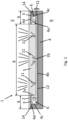
- the lighting system of the outer panel is shown in the drawings in a schematic sectional view and has a front side (V) and a rear side (R).
- the front side V is the visible side of the outer skin of the motor vehicle in the intended installation situation on the motor vehicle and is visible to a user.
- the lighting system 1 essentially has a design area 2, a housing element 4, and at least one light source 6.
- the design area 2 is designed as a cover element 5, which has a transparent or translucent light window 8 and at least one non-light-permeable section 9 with a color-imparting coating or is designed to be color-imparting.
- the cover element 5 is designed as a plastic composite component and comprises a deep-drawn, three-dimensionally formed decorative carrier 3 and at least one transparent cover layer arranged on the outside.
- the decorative carrier 3 is a plastic film, in particular a transparent plastic film, which has a colored coating/paint.
- the paint corresponds to the paint of the motor vehicle in terms of color design.
- the paint or coating is not provided in the area that forms a light window 8.
- the decorative carrier 3 can be a colored lacquer film, wherein the translucent area is produced as a punched-out portion of the decorative carrier 3.
- the foil as a decorative carrier 3 is back-injected with a transparent polymer material in an injection molding process.
- the transparent polymer material is a polymethyl methacrylate (PMMA).
- PMMA polymethyl methacrylate
- the light window 8 is accordingly formed in the cover element.
- the transparent cover layer forms the front side of the cover element and the outside of the lighting system.
- a design area 2 is formed on the cover element in the area of the transparent light window 8, which is also formed using the injection molding process.
- the material used is a synthetic, glass-like thermoplastic that can be molded when hot. This plastic is ideal for laser cutting and engraving with CO2 lasers.
- the design area 2 comprises side walls 2a and a rear surface 2b.
- the rear surface 2b is treated with a laser.
- laser engraving acrylic/PMMA/PC the surface is removed with the help of the laser to create an external engraving. This means that even the finest details can be precisely represented by laser engraving on acrylic.
- the result on transparent acrylic is a matt white engraving that can be used to represent a characteristic feature of the vehicle manufacturer and/or decorative and/or informative elements such as at least one symbol, a sign, an image, a brand symbol, for example a logo.
- the design area 2 in the area of the light window 8 is formed with local structures 11 on the inside.
- the local structures 11 in the interior are also created by changing the material using a laser.
- the local structures or engraving 11 by means of a laser produce a three-dimensional structure which does not change the front and smooth outer skin of the cover in the area of the light window 8. This means that the structure remains protected from wear and the surface on the front remains smooth and unprocessed.
- unprocessed in this context simply means that the surface on the front of the cover element is not structured by a laser. The surface remains smooth and only follows a predetermined contour if necessary.
- the lighting system 1 further comprises a housing element 4, which has a trough-shaped depression 4a with a base surface 4b and side walls 4c.
- the base surface 4b and the side walls 4c delimit the depression, which is open at the top.
- the base surface 4b has end surfaces 4d directed towards the front.
- the housing element 4 is provided with a color-imparting coating 12 at least in the area of the base surface.
- the color-imparting coating 12 corresponds in color to the color-imparting coating 12 of the cover element and is preferably the color of the vehicle (the color code of the color-imparting coatings is the same as the color code of the car paint).
- the housing element is made of a thermoplastic material such as polycarbonate (PC) or acrylonitrile butadiene styrene (ABS).
- the colored Coating is produced using conventional processes such as a painting process or a foil lamination process.
- An air gap S1 remains between the rear surface 2b of the design area 2 and the bottom surface 4b of the housing element.
- lighting is provided.
- at least one light source 6 is arranged in each installation space.
- the light sources 6 are arranged in such a way that the emitted light is coupled into the side walls 2a or into coupling surfaces of the side walls of the design area 2, which serves as a light guide body.
- the light coupled into the design area 2 in this way is subsequently decoupled and redirected on the previously processed structured rear surface 2b and radiates through the design area 2 and the light window 8 to the outside, whereby the characteristic feature is visible on the outside in the area of the light window 8.
- the light rays are symbolized by the lines.
- the characteristic feature may also include illuminated symbols, letters, characters, brand emblems, which appear and are visible from the outside in the second state.
- the lighting means 6 are arranged in the installation spaces shown on the side, hidden from the outside by the color-giving coating of the cover element 5. Furthermore, the lighting system 1 is dimensioned and designed such that the bottom surface 4b of the housing element 4 is provided with the same color-giving coating over the entire width and completely covers the light window 8 and at least a partial area of the non-transparent section of the design area 2 when viewed from the rear.
- This design means that in the first state, viewed from the outside, a uniform, consistent appearance can be seen, preferably in the color of the vehicle. This is also referred to as the "secret until lit" function.
- a three-dimensional characteristic feature of the vehicle manufacturer and/or decorative and/or informative elements such as at least one symbol, a sign, an image, a brand symbol are backlit on the visible side and the color-giving coating can still be seen as the background.
Landscapes
- Engineering & Computer Science (AREA)
- Physics & Mathematics (AREA)
- General Engineering & Computer Science (AREA)
- Mechanical Engineering (AREA)
- Optics & Photonics (AREA)
- General Physics & Mathematics (AREA)
- Manufacturing & Machinery (AREA)
- Microelectronics & Electronic Packaging (AREA)
- Vehicle Interior And Exterior Ornaments, Soundproofing, And Insulation (AREA)
- Vehicle Waterproofing, Decoration, And Sanitation Devices (AREA)
Description
- Die Erfindung betrifft ein Beleuchtungssystem für ein Außenverkleidungsteil eines Kraftfahrzeugs, wobei das Außenverkleidungsteil insbesondere ein Frontmodul ist.
- Durch die zunehmende Verbreitung von elektrischen Fahrzeugen ändern sich die Anforderungen an Frontpanele, da keine Kühlereintrittsöffnungen in demselben Maß wie für konventionelle Kraftfahrzeuge mit Verbrennungsmotoren gefordert sind.
- Frontpanele in elektrischen Fahrzeugen bekommen mehr und mehr geschlossene Kühlerverkleidungen, was eine bessere Aerodynamik des Fahrzeugs bei gleichzeitig weniger Kühlluftbedarf entspricht.
- Frontpanele können aus transparentem Polycarbonat gefertigt und mit geeigneten Dekorationselementen oder auch Funktionselementen, wie beispielsweise Beleuchtungsmodulen versehen werden. Hierfür werden die Frontpanele gemäß dem Stand der Technik in einem Zweikomponenten Spritzgussverfahren hergestellt. Die Rückseite, also die Fahrzeuginnenseite des dreidimensional geformten Frontpanels, wird anschließend lackiert, wobei die Vorderseite, also die Außenseite des Fahrzeugs, vor Lacknebel geschützt werden muss. Dazu wird die Vorderseite maskiert. Zur Herstellung von mehrfarbigen Strukturen werden eingeprägte Geometrien des Frontpanel mit einem Laser freigelegt. Anschließend erfolgt eine Beschichtung der Innenseite mit einem physikalischen Gasabscheideverfahren (PVD), um einen Chromeffekt bei gleichzeitiger Lichttransparenz zu bekommen. Die Vorderseite erhält eine Hartlackbeschichtung.
- Des Weiteren ist es bekannt in die Frontpanele separate Bauteile in Form von Designelementen wie beispielsweise Markensymbole zu integrieren. Die Bauteile können mit Chromfolie dekoriert und anschließend in entsprechende Ausnehmungen des in der Farbgestaltung des Lacks des Kraftfahrzeugs lackierten Kunststoffformteile eingesetzt werden.
- Diese dekorierten Bauteile wie beispielsweise Markensymbole können durch den Einsatz von lichtdurchlässigen Werkstoffen von der Rückseite beleuchtet werden und bilden damit eine dekorative Beleuchtungsfunktion. Derartig bekannte Verkleidungselemente mit integrierten Leuchtfunktionen haben allerdings den Nachteil, dass die Beleuchtung auch im unbeleuchteten Zustand für einen Nutzer sichtbar ist und nur dekorativ ist, und keine Funktionsbeleuchtung darstellt.
- Aus der
WO 2019/223 989 A1 ist ein hinterleuchtbares Zierelement mit einem schichtartigen Aufbau, umfassend ein Dekorelement, einen Lichtleiter, eine Lichtquelle und eine Spiegelschicht, bekannt. Das hinterleuchtbare Zierelement hat eine Sichtseite, die als schichtartige Struktur ausgebildet ist. Auf einer Rückseite eines Dekorteils ist eine Lichtleiteinheit in Form eines Lichtleitkörpers angeordnet. Die Lichtleitkörper ist gemäß einer Ausführungsform mit einer lokalen Designstruktur zur lokalen Beeinflussung des Lichts von einer Lichtquelle auf die Sichtseite ausgebildet. Die lokale Designstruktur ist dabei in einer Ausführungsform der Offenbarung als lokale Materialveränderung im Inneren des Lichtleiters ausgebildet, die mittels eines Lasers hergestellt ist. Um das von der Lichtquelle in den Lichtleitkörper eingekoppelte Licht entlang einer Richtung der sichtbaren Seite zu reflektieren, und um einen Tiefeneffekt für einen Betrachter zu erzeugen, ist zumindest auf der Rückseite des Lichtleitkörpers eine reflektierende Spiegelschicht angeordnet. - Das Dokument
DE 10 2018 211 457 A1 zeigt ein Verfahren zur Herstellung eines hinterleuchtbaren Exterieur-Bauteils, wobei zunächst ein Basisteil aus einem transparenten Kunststoff hergestellt wird, welches in einem weiteren Schritt auf der Innenfläche mit einem lichtundurchlässigen Material beschichtet wird. Zur Ausbildung von lichtdurchlässigen Strukturen wird das lichtdurchlässige Material durch Laserabtrag in den entsprechenden gewünschten strukturierten Bereichen entfernt. - Es ist Aufgabe der Erfindung, ein Beleuchtungssystem für ein Außenverkleidungsteil mit einer farbig gestalteten Sichtseite, wobei die Farbe vorzugsweise die Wagenfarbe ist, für ein Kraftfahrzeug bereitzustellen, welches zumindest in einem ersten Zustand für einen Nutzer von der Außenseite des Kraftfahrzeugs gesehen eine optisch einheitliche Gestaltung vermittelt, und ein dreidimensionales charakteristisches Merkmal nicht sichtbar ist und in einem zweiten Zustand ein dreidimensionales charakteristisches Merkmal von der Außenseite gesehen sichtbar ist, und die Sichtseite weiterhin als eine durchgehende einheitlich farbig gestaltete Oberfläche wahrnehmbar ist.
- Die Aufgabe wird durch ein Beleuchtungssystem für ein Außenverkleidungsteil mit den Merkmalen des Anspruch 1 gelöst.
- Durch das erfindungsgemäße Beleuchtungssystem eines Außenverkleidungsteils ist es möglich einen Gestaltungsbereich mit zumindest einem dreidimensional erscheinenden charakteristischen Merkmal mit einer "Verschwindefunktion" (secret until lit) zu realisieren. Dies bedeutet, dass in einem ersten Zustand für einen Nutzer dieses charakteristische Merkmal nicht sichtbar ist und der Nutzer den Eindruck eines einheitlich farbig gestalteten Außenverkleidungsteils hat. In einem zweiten Zustand ist das dreidimensional erscheinende charakteristische Merkmal für eine Nutzer von der Außenseite her sichtbar. In diesem zweiten Zustand nimmt der Nutzer auf der Sichtseite den Gestaltungsbereich mit dem dreidimensional erscheinenden charakteristischen Merkmal des Fahrzeugherstellers und/oder dekorative und/oder informative Elemente wie zumindest einem Symbol, einem Zeichen, einem Bild, einem Markensymbol und als Hintergrund weiterhin die farbgebende Beschichtung wahr.
- Dieses einheitliche Erscheinungsbild der Sichtseite, d.h. die farbgebende Beschichtung, kann durch eine Lackierung oder eine Lackfolie hergestellt sein. Die farbgebende Beschichtung ist lichtundurchlässig.
- Durch das erfindungsgemäße Beleuchtungssystem ist es möglich dem Nutzer eines Kraftfahrzeugs und/oder einem Verkehrsteilnehmer unterschiedliche beleuchtete Merkmale zumindest zeitweise zur Verfügung zu stellen. Diese Merkmale können sowohl sicherheitsrelevante Aspekte als auch Kommunikationsmöglichkeiten durch beleuchtete Symbole, Schriftzüge beinhalten. Die Merkmale können auch Designmerkmale beinhalten. Hierdurch wird eine Erweiterung der Funktionsmöglichkeiten bei beleuchteten Frontpanels erreicht. Als weitere integrierbare Funktion ist beispielsweise die Blinkerfunktion vorstellbar.
- Erfindungsgemäß ist der Gestaltungsbereich die einheitlich die Vorderseite bildende Abdeckschicht bzw. das Abdeckelement des Außenverkleidungselements, die als transparentes Kunststoffformteil das Lichtfenster und den Gestaltungsbereich in Form des zumindest einen Lichtfensters umfasst oder überdeckt, so dass keinerlei Fugen im Oberflächenbereich des Beleuchtungssystems in der verbauten Situation am Verkleidungsteil entstehen. Hierdurch werden insbesondere Abdichtprobleme bei der Integration der beleuchteten Merkmale vermieden.
- Die farbgebende Beschichtung des lichtundurchlässigen Bereichs des Abdeckelements ist dabei erfindungsgemäß die gleiche Farbe wie die farbgebende Beschichtung des Gehäuseelements, wobei diese Farbe vorzugsweise der Wagenfarbe des Kraftfahrzeugs entspricht.
- Als Außenseite oder auch Sichtseite wird der von der Außenumgebung her für einen Nutzer sichtbarer Oberflächenbereich gesehen. Die Innenseite ist dementsprechend die der Außenseite gegenüberliegende zur Innenseite weisende Seite.
- Als durchleuchtbares Verkleidungsteil wird insbesondere ein Außenverkleidungsteil wie beispielsweise ein Frontpanel, eine Stoßfängerverkleidung, eine Heckklappenverkleidung, eine Türverkleidung, eine Dachverkleidung oder ein Spoiler angesehen oder ist ein Bauteil eines der vorgenannten Teile.
- Das Außenverkleidungsteil ist dreidimensional ausgestaltet.
- Die Beleuchtungsfunktion wird durch zumindest eine Lichtquelle hergestellt. Als Lichtquelle kann eine oder können mehrere LEDs dienen. Die Lichtquelle bzw. die Lichtquellen sind jeweils hinter der bestimmungsgemäßen Sichtseite im Bereich des lichtundurchlässigen Abschnitts des Abdeckelements bzw. der Abdeckschicht angeordnet.
- Die zumindest eine Lichtquelle ist dabei derart angeordnet, dass sie ihr Licht seitlich in einen Lichteinkoppelbereich des Gestaltungselements, welches als Lichtleitkörper wirkt, einkoppeln.
- Die Erfindung wird nachfolgend beispielhaft unter Bezugnahme auf die beigefügten Zeichnungen beschrieben.
- Fig. 1
- zeigt ein Schnittbild eines Aufbaus eines Beleuchtungssystems in einer ersten Ausführungsform.
- Das erfindungsgemäße Beleuchtungssystem für ein Außenverkleidungsteil eines Kraftfahrzeugs wird nachfolgend anhand eines Beleuchtungssystems eines Frontpanels als Außenverkleidung im Frontbereich eines Elektrofahrzeugs beschrieben. Es ist selbstverständlich, dass ein derartiges Außenverkleidungsteil auch an beliebiger anderer Stelle eines Kraftfahrzeugs als Verkleidungselement eingesetzt werden kann. Das Außenverkleidungsteil ist bevorzugt auch eine Stoßfängerverkleidung, eine Heckklappenverkleidung, eine Türverkleidung, eine Dachverkleidung oder ein Spoiler oder ist ein Bauteil eines der vorgenannten Teile.
- Das Beleuchtungssystem der Außenverkleidung ist in den Zeichnungen in einer schematischen Schnittdarstellung gezeigt und weist eine Vorderseite (V) und eine Rückseite (R) auf. Die Vorderseite V ist die Sichtseite der Außenhaut des Kraftfahrzeugs in der bestimmungsgemäßen Einbausituation am Kraftfahrzeug und für einen Nutzer sichtbar.
- Das Beleuchtungssystem 1 weist im Wesentlichen einen Gestaltungsbereich 2, ein Gehäuseelement 4, sowie zumindest eine Lichtquelle 6 auf.
- In der in der
Figur 1 gezeigten Ausführungsform ist der Gestaltungsbereich 2 als Abdeckelement 5 ausgeführt, welches ein transparentes oder transluzentes Lichtfenster 8 und zumindest einen nichtlichtdurchlässigen Abschnitt 9 mit einer farbgebenden Beschichtung aufweist oder farbgebend ausgeführt ist. - Das Abdeckelement 5 ist als Kunststoffverbundbauteil ausgebildet und umfasst einen tiefgezogenen dreidimensional ausgebildeten Dekorträger 3 und zumindest eine außenseitig angeordnete transparente Abdeckschicht. Der Dekorträger 3 ist eine Kunststofffolie, insbesondere eine transparente Kunststofffolie, die eine farbige Beschichtung/Lackierung aufweist. Die Lackierung entspricht hinsichtlich der Farbgestaltung der Lackierung des Kraftfahrzeugs. Die Lackierung oder Beschichtung ist in dem Bereich, der ein Lichtfenster 8 bildet, nicht vorgesehen.
- Alternativ kann der Dekorträger 3 eine farbige Lackfolie sein, wobei der lichtdurchlässige Bereich als Ausstanzung des Dekorträgers 3 hergestellt ist.
- Die Folie als Dekorträger 3 ist in einem Spritzgießverfahren mit einem transparenten Polymermaterial hinterspritzt. In der in der
Figur 1 gezeigten Ausführungsform ist das transparente Polymermaterial ein Polymethylmethacrylat (PMMA). In dem Bereich des lichtdurchlässigen Bereichs des Dekorträgers 3 ist in dem Abdeckelement dementsprechend das Lichtfenster 8 ausgebildet. Die transparente Abdeckschicht bildet die Vorderseite des Abdeckelements und die Außenseite des Beleuchtungssystems. - Wie es aus der
Figur 1 zu dem ersten Ausführungsbeispiel zu erkennen ist, ist an dem Abdeckelement im Bereich des transparenten Lichtfensters 8 ein Gestaltungsbereich 2 ausgebildet, der ebenfalls beim Spritzgießverfahren angeformt ausgeführt ist. Das oben genannte verwendete Material ist ein synthetischer, glasähnlicher thermoplastischer Kunststoff, der warm verformbar ist. Dieser Kunststoff ist ideal für das Laserschneiden und Gravieren mit CO2-Lasern geeignet. - Der Gestaltungsbereich 2 umfasst Seitenwände 2a und eine rückseitige Fläche 2b. Die rückseitige Fläche 2b ist mithilfe eines Lasers behandelt. Bei der Lasergravur von Acryl / PMMA /PC wird die Oberfläche mit Hilfe des Lasers zu einer Außengravur abgetragen. So können auch feinste Details per Lasergravur auf Acryl präzise dargestellt werden. Das Ergebnis auf durchsichtigem Acryl ist eine mattweiße Gravur, die zur Darstellung eines charakteristischen Merkmals des Fahrzeugherstellers und/oder dekorative und/oder informative Elemente wie zumindest einem Symbol, einem Zeichen, einem Bild, einem Markensymbol, beispielsweise eines Logos, dienen kann.
- In einer weiteren Ausbildung ist der Gestaltungsbereich 2 im Bereich des Lichtfensters 8 im Inneren mit lokalen Strukturen 11 ausgebildet. Diese lokalen Strukturen 11, die in der
Figur 1 mit kleinen Kreisen dargestellt sind, dienen der Darstellung eines charakteristischen Merkmals des Fahrzeugherstellers und/oder dekorative und/oder informative Elemente wie zumindest einem Symbol, einem Zeichen, einem Bild, einem Markensymbol, beispielsweise eines Logos, wenn der als Lichtleitkörper ausgebildete Gestaltungsbereich beleuchtet ist. Die lokalen Strukturen 11 im Inneren werden ebenfalls durch Materialveränderung mittels Laser erzeugt. - Die lokalen Strukturen bzw. Gravur 11 mittels Laser erzeugt eine dreidimensionale Struktur, die aber die Vorderseite und glatte Außenhaut der Abdeckung im Bereich des Lichtfensters 8 nicht verändert. Dadurch bleibt die Struktur vor Verschleiß geschützt und die Oberfläche auf der Vorderseite glatt und unbearbeitet. Der Begriff unbearbeitet bedeutet in diesem Zusammenhang nur, dass die Oberfläche auf der Vorderseite des Abdeckelements nicht von einem Laser strukturiert wird. Die Oberfläche bleibt glatt und folgt lediglich einer vorgegebenen Kontur, wenn erforderlich.
- Das Beleuchtungssystem 1 umfasst des Weiteren ein Gehäuseelement 4, welches eine muldenförmige Vertiefung 4a mit einer Bodenfläche 4b sowie Seitenwänden 4c aufweist. Die Bodenfläche 4b sowie die Seitenwände 4c begrenzen die Vertiefung, die nach oben hin offen ist. Des Weiteren weist die Bodenfläche 4b zur Vorderseite gerichtete Stirnflächen 4d auf.
- Das Gehäuseelement 4 ist zumindest im Bereich der Bodenfläche mit einer farbgebenden Beschichtung 12 ausgeführt. Die farbgebende Beschichtung 12 entspricht hinsichtlich der Farbe der farbgebenden Beschichtung 12 des Abdeckelements und ist vorzugsweise die Wagenfarbe des Kraftfahrzeugs (Farbcode der farbgebenden Beschichtungen ist gleich Farbcode des Autolacks). Das Gehäuseelement ist aus einem thermoplastischen Kunststoffmaterial wie einem Polycarbonat (PC) oder Acrylnitril-Butadien-Styrol (ABS) hergestellt. Die farbige Beschichtung wird in üblichen Verfahren wie einem Lackierverfahren oder einem Folienkaschierverfahren hergestellt.
- Wie es aus der Schnittdarstellung zu erkennen ist, liegt das Abdeckelement 5 derart auf dem Gehäuseelement 4 auf, dass der Gestaltungsbereich 2 mit seiner Erstreckung in der Höhe vollständig in die muldenförmige Vertiefung 4a ragt und von allen Seitenwänden 4c des Gehäuseelements 4 umgeben ist. Das Abdeckelement 5 ist auf den Stirnseiten 4d des Gehäuseelements 4 über eine Klebeverbindung 14 wie ein Klebeband fixiert gehalten.
- Zwischen rückseitiger Fläche 2b des Gestaltungsbereichs 2 und Bodenfläche 4b des Gehäuseelements verbleibt dabei ein Luftspalt S1.
- Zwischen zwei Seitenwänden 2a des Gestaltungsbereichs und den jeweils korrespondierend gegenüberliegenden Seitenwänden 4c des Gehäuseelements 4 verbleibt ebenfalls ein Einbauraum.
- Um die obenstehend beschriebenen lokalen Strukturen 11 des Gestaltungsbereichs von der Außenseite sichtbar zu machen, ist eine Beleuchtung vorgesehen. Wie es aus der
Figur 1 zu erkennen ist, ist in jedem Einbauraum zumindest ein Leuchtmittel 6 angeordnet. Die Leuchtmittel 6 sind dabei derart ausgerichtet angeordnet, dass das ausgestrahlte Licht in die Seitenwände 2a bzw. in Einkoppelflächen der Seitenwände des Gestaltungsbereichs 2 der als Lichtleitkörper dient eingekoppelt wird. Das derart in den Gestaltungsbereich 2 eingekoppelte Licht wird im weiteren Verlauf an der vorher bearbeiteten strukturierten rückseitigen Fläche 2b ausgekoppelt und umgelenkt und durch den Gestaltungsbereich 2 und das Lichtfenster 8 zur Außenseite hin ausstrahlt, wodurch das charakteristische Merkmal auf der Außenseite im Bereich des Lichtfensters 8 sichtbar ist. Die Lichtstrahlen sind durch die Striche symbolisiert dargestellt. - Das charakteristische Merkmal kann auch beleuchtete Symbole, Buchstaben, Schriftzeichen, Markenembleme umfassen, die in dem zweiten Zustand von der Außenseite in Erscheinung treten und sichtbar sind.
- Wie es weiterhin aus der schematischen Darstellung der
Figur 1 zu erkennen ist, sind die Leuchtmittel 6 in den seitlich dargestellten Einbauräumen von der Außenseite gesehen von der farbgebenden Beschichtung des Abdeckelements 5 verdeckt angeordnet. Des Weiteren ist das Beleuchtungssystem 1 derart dimensioniert und ausgeführt, dass die Bodenfläche 4b des Gehäuseelements 4 über die gesamte Breite mit der gleichen farbgebenden Beschichtung versehen ist und das Lichtfenster 8 und zumindest einen Teilbereich des nichtlichtdurchlässigen Abschnitts des Gestaltungsbereichs 2 von der Rückseite gesehen komplett abdeckt. Durch diese Ausführung ist in dem ersten Zustand von der Außenseite gesehen ein einheitliches durchgängiges Erscheinungsbild, vorzugsweise in der Wagenfarbe zu erkennen. Dies wird auch als "secret until lit" Funktion bezeichnet. In dem zweiten Zustand ist auf der Sichtseite ein dreidimensional erscheinendes charakteristischen Merkmal des Fahrzeugherstellers und/oder dekorative und/oder informative Elemente wie zumindest einem Symbol, einem Zeichen, einem Bild, einem Markensymbol hinterleuchtet und als Hintergrund weiterhin die farbgebende Beschichtung wahrnehmbar. -
- 1
- Beleuchtungssystem
- 2
- Gestaltungsbereich
- 2a
- Seitenwände
- 2b
- rückseitige Fläche
- 3
- Dekorträger
- 4
- Gehäuseelement
- 4a
- Vertiefung
- 4b
- Bodenfläche
- 4c
- Seitenwände
- 4d
- Stirnflächen
- 5
- Abdeckelement
- 6
- Lichtquelle
- 8
- Lichtfenster
- 9
- nichtlichtdurchlässiger Fensterabschnitt
- 11
- Gravur
- 12
- Beschichtung
- 14
- Klebeverbindung
Claims (4)
- Beleuchtungssystem (1) für ein Außenverkleidungsteil eines Kraftfahrzeugs, mit zumindest• einem Gestaltungsbereich (2), der eine zur Außenseite weisende Sichtseite und eine Rückseite mit einer rückseitigen Fläche (2b) sowie Seitenflächen (2a) aufweist, wobei der Gestaltungsbereich (2) als Lichtleitkörper aus einem transparenten thermoplastischen Material welches für eine Lasergravur geeignet ist, vorzugsweise einem PMMA besteht, wobei der Gestaltungsbereich (2) ein Lichtfenster (8) bildet und für eine individuelle Anpassung des Fahrzeugs und/oder zur Darstellung eines auf der Sichtseite dreidimensional erscheinendes charakteristischen Merkmals mittels einer Laserstruktur auf der rückseitigen Fläche (2b) oder mittels lokaler Strukturen (11) im Inneren des Gestaltungsbereichs (2) bearbeitet ist,• einem Gehäuseelement (4), welches eine muldenförmige Ausnehmung (4a) mit einer Bodenfläche (4b) und Seitenflächen (4c) aufweist,• wobei der Gestaltungsbereich (2) derart an dem Gehäuseelement (4) angebunden ist, dass der Gestaltungsbereich (2) zumindest mit einem rückseitigen Abschnitt von der Ausnehmung (4a) umgeben ist und zwischen rückseitiger Fläche (2b) des Gestaltungsbereichs (2) und Bodenfläche (4b) ein Luftspalt verbleibt, und dass zwischen zumindest einer Seitenfläche (2a) des Gestaltungsbereichs (2) und Seitenfläche (4c) des Gehäuseelements (2) ein Einbauraum verbleibt,• wobei in dem zumindest einen Einbauraum zumindest eine Lichtquelle (6) angeordnet ist, wobei das Licht in zumindest eine Seitenfläche (2a) des Gestaltungsbereichs (2) einkoppelbar ist, und im weiteren Strahlengang an der Laserstruktur bzw. an den lokalen Strukturen (11) auskoppelbar und anschließend den Gestaltungsbereich (2) auf der Außenseite zur Erzeugung des dreidimensionalen charakteristischen Merkmals durchstrahlt,• wobei die zumindest eine Lichtquelle (6) in dem Einbauraum durch eine erste farbgebende Beschichtung (3) abgedeckt ist, dadurch gekennzeichnet,• dass die Bodenfläche (4b) des Gehäuseelements (4) mit einer zweiten farbgebenden Beschichtung (12) versehen ist,• und dass der Gestaltungsbereich (2) als Abdeckelement (5) ausgeführt ist, welches den Gestaltungsbereich (2) in Form des zumindest eines Lichtfensters (8) und zumindest einen nichtlichtdurchlässigen Abschnitt mit der ersten farbgebenden Beschichtung aufweist, wobei dieser nichtlichtdurchlässige Abschnitt die Lichtquelle (6) im Einbauraum von der Sichtseite verdeckt,• und dass die erste farbgebende Beschichtung des Abdeckelements (5) und die zweite farbgebende Beschichtung (12) der Bodenfläche (4b) des Gehäuseelements (4) mit der gleichen Farbe, vorzugsweise der Wagenfarbe ausgeführt sind.
- Beleuchtungssystem (1) nach Anspruch 1, dadurch gekennzeichnet, dass die erste und/oder die zweite farbgebende Beschichtung eine farbige lichtdurchlässige Folie oder eine Lackierung ist.
- Beleuchtungssystem (1) nach einem der vorangehenden Ansprüche, dadurch gekennzeichnet, dass die zumindest eine Lichtquelle (6) eine oder mehrere LEDs oder ein Lichtband ist.
- Außenverkleidungsteil mit einem Beleuchtungssystem (1) nach einem der vorangehenden Ansprüche, dadurch gekennzeichnet, dass das Gehäuseelement (4) an das Außenverkleidungselement angebunden oder einteilig mit dem Außenverkleidungselement ausgeführt ist.
Applications Claiming Priority (1)
| Application Number | Priority Date | Filing Date | Title |
|---|---|---|---|
| DE102022210250.9A DE102022210250B4 (de) | 2022-09-28 | 2022-09-28 | Beleuchtungssystem für ein Außenverkleidungsteil eines Kraftfahrzeugs |
Publications (2)
| Publication Number | Publication Date |
|---|---|
| EP4344949A1 EP4344949A1 (de) | 2024-04-03 |
| EP4344949B1 true EP4344949B1 (de) | 2024-10-23 |
Family
ID=88093159
Family Applications (1)
| Application Number | Title | Priority Date | Filing Date |
|---|---|---|---|
| EP23197622.6A Active EP4344949B1 (de) | 2022-09-28 | 2023-09-15 | Beleuchtungssystem für ein aussenverkleidungsteil eines kraftfahrzeugs |
Country Status (5)
| Country | Link |
|---|---|
| US (1) | US12291144B2 (de) |
| EP (1) | EP4344949B1 (de) |
| CN (1) | CN117781227A (de) |
| DE (1) | DE102022210250B4 (de) |
| HU (1) | HUE069780T2 (de) |
Families Citing this family (2)
| Publication number | Priority date | Publication date | Assignee | Title |
|---|---|---|---|---|
| DE102023109096A1 (de) * | 2023-04-11 | 2024-10-17 | Webasto SE | Fahrzeugscheibe mit Beleuchtungseinrichtung und Lichtauskoppeleinrichtung |
| KR20260003978A (ko) * | 2024-07-01 | 2026-01-08 | 현대모비스 주식회사 | 차량용 조명장치 |
Family Cites Families (33)
| Publication number | Priority date | Publication date | Assignee | Title |
|---|---|---|---|---|
| US4929866A (en) * | 1987-11-17 | 1990-05-29 | Mitsubishi Cable Industries, Ltd. | Light emitting diode lamp |
| US5101325A (en) * | 1990-03-20 | 1992-03-31 | General Electric Company | Uniform illumination of large, thin surfaces particularly suited for automotive applications |
| US5386347A (en) * | 1992-10-02 | 1995-01-31 | Photo Craft Co., Ltd. | Illuminating apparatus and a method of manufacturing an edge light conductor for use therein |
| JP4596100B2 (ja) * | 2000-09-28 | 2010-12-08 | 豊田合成株式会社 | 照明装置 |
| US6880960B2 (en) * | 2003-03-26 | 2005-04-19 | E'sam Co., Ltd. | Side mirror cover and side mirror body |
| WO2005025275A1 (de) * | 2003-08-28 | 2005-03-17 | Fraunhofer-Gesellschaft zur Förderung der angewandten Forschung e.V. | Leuchtkörper an einer karosserie eines fahrzeugs |
| TW200641416A (en) * | 2005-05-31 | 2006-12-01 | Bright View Electronics Co Ltd | A lighting device providing longitudinal illumination |
| WO2007083805A1 (ja) * | 2006-01-23 | 2007-07-26 | Fujifilm Corporation | 面状照明装置 |
| JP2008070697A (ja) * | 2006-09-15 | 2008-03-27 | Toyoda Gosei Co Ltd | 表示装置 |
| GB0706289D0 (en) * | 2007-03-30 | 2007-05-09 | 3M Innovative Properties Co | Illuminated license plate |
| TWI371621B (en) * | 2007-04-17 | 2012-09-01 | Au Optronics Corp | Backlight module |
| FR2937710B1 (fr) * | 2008-10-27 | 2013-05-17 | Saint Gobain | Module a diodes electroluminescentes pour vehicule, support a diodes, fabrications |
| DE102009055733A1 (de) * | 2009-04-03 | 2010-10-14 | Johnson Controls Interiors Gmbh & Co. Kg | Beleuchtungseinrichtung |
| JP2012174641A (ja) * | 2011-02-24 | 2012-09-10 | Koito Mfg Co Ltd | 車両用灯具 |
| TWI404893B (zh) * | 2011-05-13 | 2013-08-11 | 南臺科技大學 | 無導光板之led發光構造 |
| FR2982196B1 (fr) * | 2011-11-07 | 2015-07-17 | Saint Gobain | Vitrage de signalisation lumineuse pour vehicule |
| JP5937836B2 (ja) * | 2012-02-07 | 2016-06-22 | 株式会社小糸製作所 | 車両用灯具 |
| DE102012222684B4 (de) * | 2012-12-11 | 2022-02-03 | Bayerische Motoren Werke Aktiengesellschaft | Beleuchtungseinrichtung für ein Kraftfahrzeug |
| JP6174329B2 (ja) * | 2013-02-07 | 2017-08-02 | 株式会社小糸製作所 | 車両用灯具 |
| US20160011362A1 (en) * | 2014-07-11 | 2016-01-14 | Chien-Chung Jeng | Traffic direction lights |
| KR102305599B1 (ko) * | 2014-10-22 | 2021-09-28 | 엘지이노텍 주식회사 | 조명장치 및 이를 포함하는 차량용 램프 |
| FR3030684B1 (fr) * | 2014-12-19 | 2019-09-06 | Valeo Vision | Dispositif lumineux comprenant des sources surfaciques de lumiere |
| KR102588792B1 (ko) * | 2016-02-15 | 2023-10-18 | 엘지이노텍 주식회사 | 램프 및 이를 구비하는 차량 |
| JP7203366B2 (ja) * | 2017-03-16 | 2023-01-13 | パナソニックIpマネジメント株式会社 | 表示装置 |
| FR3070070A1 (fr) * | 2017-08-14 | 2019-02-15 | Koito Manufacturing Co., Ltd. | Guide de lumiere en forme de tige et lampe de vehicule |
| TWI653416B (zh) * | 2018-03-12 | 2019-03-11 | 聯嘉光電股份有限公司 | 車載雙功能發光模組及車載雙功能照明燈組 |
| JP2019169241A (ja) * | 2018-03-22 | 2019-10-03 | スタンレー電気株式会社 | 車両用灯具 |
| EP3572282A1 (de) * | 2018-05-24 | 2019-11-27 | WEIDPLAS GmbH | Hinterleuchtbares zierelement für ein fahrzeug |
| DE102018211457A1 (de) * | 2018-07-11 | 2020-01-16 | Bayerische Motoren Werke Aktiengesellschaft | Verfahren zur Herstellung eines Exterieur-Bauteils und Exterieur-Bauteil |
| DE102018009248B4 (de) * | 2018-11-21 | 2024-11-07 | Mercedes-Benz Group AG | Kraftfahrzeug-Heckleuchte mit einem Lichtleiter, auf dessen Rückseite eine Grafik angeordnet ist, die dasselbe grafische Muster aufweist wie in die Vorderseite des Lichtleiters eingebrachte Auskopplungsstrukturen |
| CN109611788A (zh) * | 2019-01-24 | 2019-04-12 | 华域视觉科技(上海)有限公司 | 三维光学组件、灯具及产生三维深度发光效果的方法 |
| JP7555282B2 (ja) * | 2021-02-10 | 2024-09-24 | 株式会社小糸製作所 | 車両用ランプ |
| FR3128770B1 (fr) * | 2021-10-29 | 2024-01-12 | Valeo Vision | Dispositif lumineux pour véhicule |
-
2022
- 2022-09-28 DE DE102022210250.9A patent/DE102022210250B4/de active Active
-
2023
- 2023-09-15 HU HUE23197622A patent/HUE069780T2/hu unknown
- 2023-09-15 EP EP23197622.6A patent/EP4344949B1/de active Active
- 2023-09-20 US US18/370,455 patent/US12291144B2/en active Active
- 2023-09-27 CN CN202311271766.9A patent/CN117781227A/zh active Pending
Also Published As
| Publication number | Publication date |
|---|---|
| US20240101022A1 (en) | 2024-03-28 |
| DE102022210250A1 (de) | 2024-03-28 |
| US12291144B2 (en) | 2025-05-06 |
| EP4344949A1 (de) | 2024-04-03 |
| DE102022210250B4 (de) | 2024-04-25 |
| HUE069780T2 (hu) | 2025-04-28 |
| CN117781227A (zh) | 2024-03-29 |
Similar Documents
| Publication | Publication Date | Title |
|---|---|---|
| EP3976423B1 (de) | Hinterleuchtbares bauteil | |
| EP2416990B1 (de) | Blende für ein kraftfahrzeug | |
| DE102014112470B4 (de) | Ausstattungsteil mit leuchtender sichtseite | |
| EP4344949B1 (de) | Beleuchtungssystem für ein aussenverkleidungsteil eines kraftfahrzeugs | |
| DE102017214943A1 (de) | Verkleidungselement an einen Fahrzeug sowie Verfahren zur Herstellung | |
| EP3878695B1 (de) | Beleuchtetes markenemblem | |
| EP2419297A1 (de) | Dekorelement und verfahren zu dessen herstellung und verfahren zu dessen ansteuerung | |
| DE102008064233B4 (de) | Einstiegsleiste für Kraftfahrzeuge | |
| EP2684744A1 (de) | Zierteil für Kraftfahrzeuge und Verfahren zu seiner Herstellung | |
| DE202020104697U1 (de) | Verkleidungsanordnung für ein Fahrzeug sowie Fahrzeug mit der Verkleidungsanordnung | |
| WO2017016763A1 (de) | Durchleuchtbares dekorelement und verfahren zu dessen herstellung | |
| DE102021100532A1 (de) | Dekorteil | |
| EP4384367A1 (de) | Spritzgussfertigung eines bauteils | |
| EP1436167B1 (de) | Dekorelement und mit einem dekorelement versehenes kunststoffteil | |
| EP1725443B1 (de) | Fahrzeug folienbauteil und verfahren zu dessen herstellung | |
| EP3616988B1 (de) | Beleuchtungsvorrichtung für ein personen- und/oder gütertransportmittel, verkleidungsbauteil für ein personen- und/oder gütertransportmittel mit einer derartigen beleuchtungsvorrichtung sowie ein personen- und/oder gütertransportmittel mit einem solchen verkleidungsbauteil | |
| EP3299217B1 (de) | Abdeckungseinrichtung, system, karosseriebauteil, karosseriebauteilsystem und fahrzeug | |
| EP3670135B1 (de) | Kaschierte folie, damit hergestelltes kunststoffbauteil, sowie verfahren und werkzeug dafür | |
| DE19707614C2 (de) | Karosserieteil eines Kraftfahrzeuges | |
| DE102019217659A1 (de) | Verkleidungselement an einem Fahrzeug und Verfahren zur Herstellung | |
| EP4339022B1 (de) | Verkleidungsteil für ein kraftfahrzeug | |
| DE102018212152A1 (de) | Dekorteil | |
| DE102016214268A1 (de) | Blende zur Innenausstattung eines Kraftfahrzeugs, Verfahren zum Herstellen einer Blende und Kraftfahrzeug | |
| EP4074486B1 (de) | Verfahren zum herstellen von bauteilen einer aussenhaut eines fahrzeugs | |
| DE202020002576U1 (de) | Selektiv verchromte und hintergrundbeleuchtbare Fahrzeugkomponente |
Legal Events
| Date | Code | Title | Description |
|---|---|---|---|
| PUAI | Public reference made under article 153(3) epc to a published international application that has entered the european phase |
Free format text: ORIGINAL CODE: 0009012 |
|
| STAA | Information on the status of an ep patent application or granted ep patent |
Free format text: STATUS: REQUEST FOR EXAMINATION WAS MADE |
|
| 17P | Request for examination filed |
Effective date: 20240105 |
|
| AK | Designated contracting states |
Kind code of ref document: A1 Designated state(s): AL AT BE BG CH CY CZ DE DK EE ES FI FR GB GR HR HU IE IS IT LI LT LU LV MC ME MK MT NL NO PL PT RO RS SE SI SK SM TR |
|
| GRAP | Despatch of communication of intention to grant a patent |
Free format text: ORIGINAL CODE: EPIDOSNIGR1 |
|
| STAA | Information on the status of an ep patent application or granted ep patent |
Free format text: STATUS: GRANT OF PATENT IS INTENDED |
|
| RIC1 | Information provided on ipc code assigned before grant |
Ipc: B60R 13/04 20060101ALI20240516BHEP Ipc: F21V 8/00 20060101ALI20240516BHEP Ipc: G02B 5/02 20060101ALI20240516BHEP Ipc: F21W 104/00 20180101ALI20240516BHEP Ipc: F21S 43/20 20180101ALI20240516BHEP Ipc: F21S 43/249 20180101ALI20240516BHEP Ipc: F21S 43/245 20180101ALI20240516BHEP Ipc: F21S 43/239 20180101ALI20240516BHEP Ipc: F21S 43/14 20180101ALI20240516BHEP Ipc: B60R 19/50 20060101ALI20240516BHEP Ipc: B60R 13/00 20060101ALI20240516BHEP Ipc: B60Q 1/00 20060101AFI20240516BHEP |
|
| INTG | Intention to grant announced |
Effective date: 20240613 |
|
| GRAS | Grant fee paid |
Free format text: ORIGINAL CODE: EPIDOSNIGR3 |
|
| GRAA | (expected) grant |
Free format text: ORIGINAL CODE: 0009210 |
|
| STAA | Information on the status of an ep patent application or granted ep patent |
Free format text: STATUS: THE PATENT HAS BEEN GRANTED |
|
| AK | Designated contracting states |
Kind code of ref document: B1 Designated state(s): AL AT BE BG CH CY CZ DE DK EE ES FI FR GB GR HR HU IE IS IT LI LT LU LV MC ME MK MT NL NO PL PT RO RS SE SI SK SM TR |
|
| REG | Reference to a national code |
Ref country code: GB Ref legal event code: FG4D Free format text: NOT ENGLISH |
|
| REG | Reference to a national code |
Ref country code: CH Ref legal event code: EP |
|
| REG | Reference to a national code |
Ref country code: DE Ref legal event code: R096 Ref document number: 502023000232 Country of ref document: DE |
|
| REG | Reference to a national code |
Ref country code: IE Ref legal event code: FG4D Free format text: LANGUAGE OF EP DOCUMENT: GERMAN |
|
| REG | Reference to a national code |
Ref country code: LT Ref legal event code: MG9D |
|
| REG | Reference to a national code |
Ref country code: NL Ref legal event code: MP Effective date: 20241023 Ref country code: SK Ref legal event code: T3 Ref document number: E 45717 Country of ref document: SK |
|
| PG25 | Lapsed in a contracting state [announced via postgrant information from national office to epo] |
Ref country code: NL Free format text: LAPSE BECAUSE OF FAILURE TO SUBMIT A TRANSLATION OF THE DESCRIPTION OR TO PAY THE FEE WITHIN THE PRESCRIBED TIME-LIMIT Effective date: 20241023 |
|
| PG25 | Lapsed in a contracting state [announced via postgrant information from national office to epo] |
Ref country code: NL Free format text: LAPSE BECAUSE OF FAILURE TO SUBMIT A TRANSLATION OF THE DESCRIPTION OR TO PAY THE FEE WITHIN THE PRESCRIBED TIME-LIMIT Effective date: 20241023 |
|
| PG25 | Lapsed in a contracting state [announced via postgrant information from national office to epo] |
Ref country code: HR Free format text: LAPSE BECAUSE OF FAILURE TO SUBMIT A TRANSLATION OF THE DESCRIPTION OR TO PAY THE FEE WITHIN THE PRESCRIBED TIME-LIMIT Effective date: 20241023 Ref country code: IS Free format text: LAPSE BECAUSE OF FAILURE TO SUBMIT A TRANSLATION OF THE DESCRIPTION OR TO PAY THE FEE WITHIN THE PRESCRIBED TIME-LIMIT Effective date: 20250223 Ref country code: PT Free format text: LAPSE BECAUSE OF FAILURE TO SUBMIT A TRANSLATION OF THE DESCRIPTION OR TO PAY THE FEE WITHIN THE PRESCRIBED TIME-LIMIT Effective date: 20250224 |
|
| PG25 | Lapsed in a contracting state [announced via postgrant information from national office to epo] |
Ref country code: FI Free format text: LAPSE BECAUSE OF FAILURE TO SUBMIT A TRANSLATION OF THE DESCRIPTION OR TO PAY THE FEE WITHIN THE PRESCRIBED TIME-LIMIT Effective date: 20241023 |
|
| PG25 | Lapsed in a contracting state [announced via postgrant information from national office to epo] |
Ref country code: BG Free format text: LAPSE BECAUSE OF FAILURE TO SUBMIT A TRANSLATION OF THE DESCRIPTION OR TO PAY THE FEE WITHIN THE PRESCRIBED TIME-LIMIT Effective date: 20241023 |
|
| PG25 | Lapsed in a contracting state [announced via postgrant information from national office to epo] |
Ref country code: ES Free format text: LAPSE BECAUSE OF FAILURE TO SUBMIT A TRANSLATION OF THE DESCRIPTION OR TO PAY THE FEE WITHIN THE PRESCRIBED TIME-LIMIT Effective date: 20241023 |
|
| PG25 | Lapsed in a contracting state [announced via postgrant information from national office to epo] |
Ref country code: NO Free format text: LAPSE BECAUSE OF FAILURE TO SUBMIT A TRANSLATION OF THE DESCRIPTION OR TO PAY THE FEE WITHIN THE PRESCRIBED TIME-LIMIT Effective date: 20250123 |
|
| PG25 | Lapsed in a contracting state [announced via postgrant information from national office to epo] |
Ref country code: LV Free format text: LAPSE BECAUSE OF FAILURE TO SUBMIT A TRANSLATION OF THE DESCRIPTION OR TO PAY THE FEE WITHIN THE PRESCRIBED TIME-LIMIT Effective date: 20241023 Ref country code: GR Free format text: LAPSE BECAUSE OF FAILURE TO SUBMIT A TRANSLATION OF THE DESCRIPTION OR TO PAY THE FEE WITHIN THE PRESCRIBED TIME-LIMIT Effective date: 20250124 |
|
| PG25 | Lapsed in a contracting state [announced via postgrant information from national office to epo] |
Ref country code: PL Free format text: LAPSE BECAUSE OF FAILURE TO SUBMIT A TRANSLATION OF THE DESCRIPTION OR TO PAY THE FEE WITHIN THE PRESCRIBED TIME-LIMIT Effective date: 20241023 |
|
| REG | Reference to a national code |
Ref country code: HU Ref legal event code: AG4A Ref document number: E069780 Country of ref document: HU |
|
| PG25 | Lapsed in a contracting state [announced via postgrant information from national office to epo] |
Ref country code: RS Free format text: LAPSE BECAUSE OF FAILURE TO SUBMIT A TRANSLATION OF THE DESCRIPTION OR TO PAY THE FEE WITHIN THE PRESCRIBED TIME-LIMIT Effective date: 20250123 |
|
| REG | Reference to a national code |
Ref country code: DE Ref legal event code: R082 Ref document number: 502023000232 Country of ref document: DE Representative=s name: EULER, MATTHIAS, DR., DE |
|
| PG25 | Lapsed in a contracting state [announced via postgrant information from national office to epo] |
Ref country code: SM Free format text: LAPSE BECAUSE OF FAILURE TO SUBMIT A TRANSLATION OF THE DESCRIPTION OR TO PAY THE FEE WITHIN THE PRESCRIBED TIME-LIMIT Effective date: 20241023 |
|
| PG25 | Lapsed in a contracting state [announced via postgrant information from national office to epo] |
Ref country code: DK Free format text: LAPSE BECAUSE OF FAILURE TO SUBMIT A TRANSLATION OF THE DESCRIPTION OR TO PAY THE FEE WITHIN THE PRESCRIBED TIME-LIMIT Effective date: 20241023 |
|
| PG25 | Lapsed in a contracting state [announced via postgrant information from national office to epo] |
Ref country code: EE Free format text: LAPSE BECAUSE OF FAILURE TO SUBMIT A TRANSLATION OF THE DESCRIPTION OR TO PAY THE FEE WITHIN THE PRESCRIBED TIME-LIMIT Effective date: 20241023 |
|
| PG25 | Lapsed in a contracting state [announced via postgrant information from national office to epo] |
Ref country code: RO Free format text: LAPSE BECAUSE OF FAILURE TO SUBMIT A TRANSLATION OF THE DESCRIPTION OR TO PAY THE FEE WITHIN THE PRESCRIBED TIME-LIMIT Effective date: 20241023 |
|
| REG | Reference to a national code |
Ref country code: DE Ref legal event code: R097 Ref document number: 502023000232 Country of ref document: DE |
|
| PG25 | Lapsed in a contracting state [announced via postgrant information from national office to epo] |
Ref country code: IT Free format text: LAPSE BECAUSE OF FAILURE TO SUBMIT A TRANSLATION OF THE DESCRIPTION OR TO PAY THE FEE WITHIN THE PRESCRIBED TIME-LIMIT Effective date: 20241023 |
|
| PLBE | No opposition filed within time limit |
Free format text: ORIGINAL CODE: 0009261 |
|
| STAA | Information on the status of an ep patent application or granted ep patent |
Free format text: STATUS: NO OPPOSITION FILED WITHIN TIME LIMIT |
|
| PG25 | Lapsed in a contracting state [announced via postgrant information from national office to epo] |
Ref country code: SE Free format text: LAPSE BECAUSE OF FAILURE TO SUBMIT A TRANSLATION OF THE DESCRIPTION OR TO PAY THE FEE WITHIN THE PRESCRIBED TIME-LIMIT Effective date: 20241023 |
|
| 26N | No opposition filed |
Effective date: 20250724 |
|
| PGFP | Annual fee paid to national office [announced via postgrant information from national office to epo] |
Ref country code: DE Payment date: 20250919 Year of fee payment: 3 |
|
| PGFP | Annual fee paid to national office [announced via postgrant information from national office to epo] |
Ref country code: HU Payment date: 20250922 Year of fee payment: 3 |
|
| PGFP | Annual fee paid to national office [announced via postgrant information from national office to epo] |
Ref country code: AT Payment date: 20251020 Year of fee payment: 3 Ref country code: FR Payment date: 20250922 Year of fee payment: 3 |
|
| PGFP | Annual fee paid to national office [announced via postgrant information from national office to epo] |
Ref country code: CZ Payment date: 20250908 Year of fee payment: 3 |
|
| PGFP | Annual fee paid to national office [announced via postgrant information from national office to epo] |
Ref country code: SK Payment date: 20250909 Year of fee payment: 3 |