EP2412938A2 - Wellenanordnung für einen Gasturbinenmotor - Google Patents
Wellenanordnung für einen Gasturbinenmotor Download PDFInfo
- Publication number
- EP2412938A2 EP2412938A2 EP11176210A EP11176210A EP2412938A2 EP 2412938 A2 EP2412938 A2 EP 2412938A2 EP 11176210 A EP11176210 A EP 11176210A EP 11176210 A EP11176210 A EP 11176210A EP 2412938 A2 EP2412938 A2 EP 2412938A2
- Authority
- EP
- European Patent Office
- Prior art keywords
- fluid
- fluid passages
- shaft
- race
- radius
- Prior art date
- Legal status (The legal status is an assumption and is not a legal conclusion. Google has not performed a legal analysis and makes no representation as to the accuracy of the status listed.)
- Granted
Links
- 239000012530 fluid Substances 0.000 claims abstract description 117
- 238000005096 rolling process Methods 0.000 description 2
- 238000001816 cooling Methods 0.000 description 1
- 230000002349 favourable effect Effects 0.000 description 1
- 238000005461 lubrication Methods 0.000 description 1
- 239000010705 motor oil Substances 0.000 description 1
- 230000002093 peripheral effect Effects 0.000 description 1
Images

Classifications
-
- F—MECHANICAL ENGINEERING; LIGHTING; HEATING; WEAPONS; BLASTING
- F01—MACHINES OR ENGINES IN GENERAL; ENGINE PLANTS IN GENERAL; STEAM ENGINES
- F01D—NON-POSITIVE DISPLACEMENT MACHINES OR ENGINES, e.g. STEAM TURBINES
- F01D25/00—Component parts, details, or accessories, not provided for in, or of interest apart from, other groups
- F01D25/16—Arrangement of bearings; Supporting or mounting bearings in casings
-
- F—MECHANICAL ENGINEERING; LIGHTING; HEATING; WEAPONS; BLASTING
- F01—MACHINES OR ENGINES IN GENERAL; ENGINE PLANTS IN GENERAL; STEAM ENGINES
- F01D—NON-POSITIVE DISPLACEMENT MACHINES OR ENGINES, e.g. STEAM TURBINES
- F01D25/00—Component parts, details, or accessories, not provided for in, or of interest apart from, other groups
- F01D25/18—Lubricating arrangements
-
- F—MECHANICAL ENGINEERING; LIGHTING; HEATING; WEAPONS; BLASTING
- F16—ENGINEERING ELEMENTS AND UNITS; GENERAL MEASURES FOR PRODUCING AND MAINTAINING EFFECTIVE FUNCTIONING OF MACHINES OR INSTALLATIONS; THERMAL INSULATION IN GENERAL
- F16C—SHAFTS; FLEXIBLE SHAFTS; ELEMENTS OR CRANKSHAFT MECHANISMS; ROTARY BODIES OTHER THAN GEARING ELEMENTS; BEARINGS
- F16C33/00—Parts of bearings; Special methods for making bearings or parts thereof
- F16C33/30—Parts of ball or roller bearings
- F16C33/66—Special parts or details in view of lubrication
- F16C33/6637—Special parts or details in view of lubrication with liquid lubricant
- F16C33/6659—Details of supply of the liquid to the bearing, e.g. passages or nozzles
- F16C33/6677—Details of supply of the liquid to the bearing, e.g. passages or nozzles from radial inside, e.g. via a passage through the shaft and/or inner ring
-
- F—MECHANICAL ENGINEERING; LIGHTING; HEATING; WEAPONS; BLASTING
- F05—INDEXING SCHEMES RELATING TO ENGINES OR PUMPS IN VARIOUS SUBCLASSES OF CLASSES F01-F04
- F05D—INDEXING SCHEME FOR ASPECTS RELATING TO NON-POSITIVE-DISPLACEMENT MACHINES OR ENGINES, GAS-TURBINES OR JET-PROPULSION PLANTS
- F05D2240/00—Components
- F05D2240/50—Bearings
- F05D2240/54—Radial bearings
-
- F—MECHANICAL ENGINEERING; LIGHTING; HEATING; WEAPONS; BLASTING
- F16—ENGINEERING ELEMENTS AND UNITS; GENERAL MEASURES FOR PRODUCING AND MAINTAINING EFFECTIVE FUNCTIONING OF MACHINES OR INSTALLATIONS; THERMAL INSULATION IN GENERAL
- F16C—SHAFTS; FLEXIBLE SHAFTS; ELEMENTS OR CRANKSHAFT MECHANISMS; ROTARY BODIES OTHER THAN GEARING ELEMENTS; BEARINGS
- F16C19/00—Bearings with rolling contact, for exclusively rotary movement
- F16C19/02—Bearings with rolling contact, for exclusively rotary movement with bearing balls essentially of the same size in one or more circular rows
- F16C19/04—Bearings with rolling contact, for exclusively rotary movement with bearing balls essentially of the same size in one or more circular rows for radial load mainly
- F16C19/06—Bearings with rolling contact, for exclusively rotary movement with bearing balls essentially of the same size in one or more circular rows for radial load mainly with a single row or balls
-
- F—MECHANICAL ENGINEERING; LIGHTING; HEATING; WEAPONS; BLASTING
- F16—ENGINEERING ELEMENTS AND UNITS; GENERAL MEASURES FOR PRODUCING AND MAINTAINING EFFECTIVE FUNCTIONING OF MACHINES OR INSTALLATIONS; THERMAL INSULATION IN GENERAL
- F16C—SHAFTS; FLEXIBLE SHAFTS; ELEMENTS OR CRANKSHAFT MECHANISMS; ROTARY BODIES OTHER THAN GEARING ELEMENTS; BEARINGS
- F16C2360/00—Engines or pumps
- F16C2360/23—Gas turbine engines
Definitions
- This disclosure relates generally to a shaft assembly for a gas turbine engine.
- Most axial gas turbine engines include a high speed shaft extending between a high speed compressor section and a high speed turbine section, and a low speed shaft extending between a low speed compressor section and a low speed turbine section.
- the shafts extend axially and are rotatable about an axial centerline.
- the position of the shafts and peripheral elements surrounding the shafts are maintained by using bearings that not only permit the relative rotation, but also support loads transmitted within the engine.
- the cooling and lubrication of these bearings is of paramount importance to the operational ability and durability of the engine.
- What is needed is a shaft assembly that enables a bearing to be sufficiently lubricated and cooled, one that can be utilized at higher speeds than most prior art engines, one that is configured to provide a favorable stress loading, and one that is readily manufacturable.
- a shaft assembly for a gas turbine engine.
- the shaft assembly includes a shaft, an annular fluid collection cavity, and a bearing.
- the shaft is rotatable around an axially extending shaft centerline.
- the fluid collection cavity is formed by an axial panel extending between a forward radial panel and an aft radial panel.
- the aft radial panel includes a plurality of fluid apertures, each fluid aperture having a center disposed at a first radius from the shaft centerline.
- the bearing includes an inner race having a shaft mounting surface and a plurality of axially extending race fluid passages.
- the shaft mounting surface is engaged with an exterior surface of the shaft, and is disposed at a second radius from the shaft centerline, wherein the second radius is less than the first radius. At least some of the axially extending race fluid passages are fluidly connected with at least some of the fluid apertures in the aft radial panel.
- a shaft assembly for a gas turbine engine.
- the shaft assembly includes a shaft, an annular fluid collection cavity, a gear and a bearing.
- the shaft is rotatable around an axially extending shaft centerline.
- the fluid collection cavity is formed by an axial panel extending between a forward radial panel and an aft radial panel.
- the aft radial panel includes a plurality of fluid apertures, each fluid aperture having a center disposed at a first radius from the shaft centerline.
- the gear is mounted onto the shaft, aft of the aft radial panel.
- the gear includes a plurality of gear fluid passages that are fluidly connected to at least some of the fluid apertures in the aft radial panel.
- Each of the gear fluid passages extends axially along a gear passage centerline that is disposed at a second radius from the shaft centerline, wherein the second radius is greater than or equal to the first radius.
- the bearing includes an inner race having a shaft mounting surface and a plurality of axially extending race fluid passages.
- the shaft mounting surface is engaged with an exterior surface of the shaft, and disposed at a third radius from the shaft centerline, wherein the third radius is less than the second radius.
- the axially extending race fluid passages are fluidly connected to the gear fluid passages.
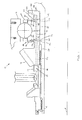
- FIG. 1 is a top half, cross-sectional diagrammatic illustration of an exemplary shaft assembly that includes an annular fluid collector, a bearing, an annular gear and an annular seal plate.
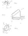
- FIG. 2 is an enlarged diagrammatic illustration of the fluid collector in FIG. 1 .
- FIG. 3 is an enlarged exploded diagrammatic illustration of the bearing in FIG. 1 .
- FIG. 4 is an enlarged diagrammatic illustration of the gear in FIG. 1 .
- FIG. 5 is an enlarged diagrammatic illustration of the seal plate in FIG. 1 .
- a shaft assembly 10 for a high speed compressor section of a gas turbine engine having an axial centerline 24.
- the present invention is not limited to high speed compressor shaft applications.
- the shaft assembly 10 can be adapted for other engine sections such as a low speed compressor section, a high or a low speed turbine section, etc.
- the shaft assembly 10 includes a compressor shaft 12, an annular fluid collector 14 and a bearing 16.
- the shaft assembly 10 includes one or both of an annular gear 18 and an annular seal plate 20.
- the compressor shaft 12 has an exterior mounting surface 22 (hereinafter “exterior surface”) that extends axially to an aft shoulder 26.
- the exterior surface 22 includes a forward mounting surface 28 and an aft mounting surface 30.
- the aft mounting surface 30 is disposed between the forward mounting surface 28 and the aft shoulder 26.
- the fluid collector 14 (also sometimes referred to as an "axial scoop") is disposed for rotation about the engine centerline 24.
- the fluid collector 14 includes an annular fluid collection cavity 32 formed by an axial panel 34, a forward radial panel 36 and an aft radial panel 38.
- the axial panel 34 extends, for example, substantially parallel to the centerline between the forward radial panel 36 and the aft radial panel 38.
- the axial panel 34 includes an inner cavity surface 40 disposed at a radius 42 (hereinafter "IC radius”) from the centerline 24.
- the forward radial panel 36 extends radially inward from the axial panel 34 to a collector tip 44.
- the aft radial panel 38 extends radially inward from the axial panel 34 to a shaft mounting surface 46.
- the aft radial panel 38 includes a plurality of circumferentially disposed fluid apertures 48 (e.g., holes, slots, etc.).
- Each fluid aperture 48 has a center 50 disposed at a radius 52 (hereinafter "FA radius") from the centerline 24.
- the FA radius 52 is less than the IC radius 42.
- an exemplary embodiment of the bearing 16 is shown as a rolling-element bearing.
- a rolling-element bearing can be configured as a ball bearing, a roller bearing, a needle bearing, a tapered roller bearing, a spherical roller bearing, a thrust bearing, etc.
- the bearing 16 is centered on the centerline 24, and includes a plurality of rolling elements 54 disposed between an inner race 56 and an outer race 58.
- the bearing 16 can further include an annular forward baffle 60 and/or an annular aft baffle 62.
- the rolling elements 54 are circumferentially aligned, and discretely located within a cage 64.
- the inner race 56 extends radially between a shaft mounting surface 66 and an outer radial race surface 68.
- the inner race 56 extends axially between a forward race surface 70 and an aft race surface 72.
- the shaft mounting surface 66 is disposed at a radius 74 (hereinafter "SMS radius") from the centerline 24.
- SMS radius 74 is less than the FA radius 52 (see FIG. 2 ).
- the inner race 56 includes a plurality of fluid passages 76, 78, 80 and/or channels 82, 84 configured to provide fluid passages through the inner race 56.
- the inner race 56 is a shown as a split ring, having two axial halves. In other embodiments, the inner race may be a unitary structure.
- the inner race 56 includes an annular base segment 86 disposed axially between an annular forward flanged protrusion 88 and an annular aft flanged protrusion 90.
- the base segment 86 extends radially between the shaft mounting surface 66 and the outer radial race surface 68.
- the base segment 86 extends axially between a forward end 92 and an aft end 94.
- the base segment 86 includes a plurality of circumferentially disposed axial fluid passages 76 and a plurality of circumferentially disposed radial channels 82, 84.
- Each axial fluid passage 76 extends along a race passage centerline 96 between the forward and the aft ends 92, 94 of the base segment 86.
- Each race passage centerline 96 is disposed at a radius 98 (hereinafter "RP radius") from the centerline 24.
- the RP radius 98 is greater than or equal to the FA radius 52 (see FIG. 2 ).
- the radial channels 82, 84 can be disposed in the forward and/or the aft ends 92, 94 of the base segment 86.
- Each radial channel 82, 84 is fluidly connected to a respective one of the axial fluid passages 76.
- Each radial channel 82, 84 extends radially outwards from the respective axial fluid passage 76 to an outer channel end 100, 102.
- the outer channel end 100, 102 is disposed at a radius 104 (hereinafter "OCE radius") from the centerline 24.
- the forward flanged protrusion 88 includes an intermediate segment 106 and a flange segment 108.
- the intermediate segment 106 extends axially forward from the base segment 86 to the forward race surface 70.
- the intermediate segment 106 extends radially inward from the outer radial race surface 68 to an axially extending channel surface 110.
- the intermediate segment 106 includes a plurality of circumferentially disposed radial fluid passages 78. Each radial fluid passage 78 extends from the axially extending channel surface 110 to the outer radial race surface 68.
- the flange segment 108 extends radially inward from the intermediate segment 106 to a flange tip 112.
- the flange segment 108 extends axially aft from the forward race surface 70 to a radially extending channel surface 114.
- the flange tip 112 is disposed at a radius 116 (hereinafter "FFT radius") from the centerline 24. In the embodiment shown in FIG. 3 , the FFT radius 116 is greater than or equal to the OCE radius 104.
- the radially extending channel surface 114 is disposed a distance from the forward end 92 of the base segment 86, thereby forming a forward annular channel 118 between the flange segment 108 and the base segment 86.
- the radially extending channel surface 114 is adapted as a grip for disassembling the split ring inner race 56.
- the aft flanged protrusion 90 includes an intermediate segment 120 and a flange segment 122.
- the intermediate segment 120 extends axially aft from the base segment 86 to the aft race surface 72.
- the intermediate segment 120 extends radially inward from the outer radial race surface 68 to an axially extending channel surface 124.
- the intermediate segment 120 includes a plurality of circumferentially disposed radial fluid passages 80. Each radial fluid passage 80 extends from the axially extending channel surface 124 to the outer radial race surface 68.
- the flange segment 122 extends radially inward from the intermediate segment 120 to a flange tip 126.
- the flange segment 122 extends axially forward from the aft race surface 72 to a radially extending channel surface 128.
- the flange tip 126 is disposed at a radius 130 (hereinafter "AFT radius") from the centerline 24.
- the AFT radius 130 is greater than or equal to the OCE radius 104.
- the radially extending channel surface 128 is disposed a distance from the aft end of the base segment 86, thereby forming an aft annular channel 132 between the flange segment 122 and the base segment 86.
- the radially extending channel surface 128 is adapted as a grip for disassembling the split ring inner race 56.
- the forward baffle 60 is disposed adjacent to the forward end 92 of the inner race 56.
- the forward baffle 60 includes a base segment 134 and a fluid guide segment 136.
- the base segment 134 extends axially from a forward surface 138 to an aft surface 140.
- the base segment 134 includes a plurality of circumferentially disposed axial fluid passages 142.
- Each axial fluid passage 142 extends along a baffle passage centerline 144 between the forward and the aft ends 138, 140 of the base segment 134.
- Each baffle passage centerline 144 is disposed at a radius 146 (hereinafter "FBP radius”) from the centerline 24.
- FBP radius radius
- the FBP radius 146 is greater than or equal to the FA radius 52 (see FIG. 2 ).
- the FBP radius 146 is also less than or equal to the RP radius 98.
- the fluid guide segment 136 has a sloped guiding surface 148 that extends radially outward from the base segment 134 to a baffle tip 150.
- the baffle tip 150 is disposed at a radius 152 (hereinafter "FBT radius") from the centerline 24.
- the FBT radius 152 is sized equal to or less than the FFT radius 116.
- the aft baffle 62 is disposed adjacent to the aft end 94 of the inner race 56.
- the aft baffle 62 includes a base segment 154 and a fluid guide segment 156.
- the base segment 154 extends axially from a forward end 158 to an aft end 160.
- the base segment 154 includes a plurality of circumferentially disposed axial fluid passages 162.
- Each axial fluid passage 162 extends along a baffle passage centerline 164 between the forward and the aft ends 158, 160 of the base segment 154.
- Each baffle passage centerline 164 is disposed at a radius 166 (hereinafter "ABP radius”) from the centerline 24.
- the ABP radius 166 is greater than or equal to the FA radius 52 (see FIG. 2 ).
- the ABP radius 166 is also greater than or equal to the RP radius 98.
- the fluid guide segment 156 has a sloped guiding surface 168 that extends radially outward from the base segment 154 to a baffle tip 170.
- the baffle tip 170 is disposed at a radius 172 (hereinafter "ABT radius") from the centerline 24.
- the ABT radius 172 is sized equal to or less than the AFT radius 130.
- an exemplary embodiment of the gear 18 is shown as a bevel gear.
- the present invention is not limited to any particular gear configuration.
- the gear 18 extends axially along the centerline 24 between a forward end 174 and an aft end 176.
- the gear 18 includes a plurality of circumferentially disposed axial fluid passages 178.
- Each axial fluid passage 178 extends along a gear passage centerline 180 between the forward and the aft ends 174, 176 of the gear 18.
- Each gear passage centerline 180 is disposed at a radius 182 (hereinafter "GP radius") from the centerline 24.
- the GP radius 182 is greater than or equal to the FA radius 52 (see FIG. 2 ).
- the GP radius 182 is also less than or equal to the FBP radius 146 (see FIG. 3 ).
- the seal plate 20 extends axially along the centerline 24, and includes a base segment 184, a seal segment 186 and a plurality of circumferentially disposed fluid passages 188.
- the base segment 184 extends axially from a forward end 190 to an aft end 192.
- the seal segment 186 extends radially from the base segment 184 to an outer radial plate surface 194.
- the seal segment 186 extends axially from the forward end 190 of the base segment 184 to an aft seal surface 196.
- Each fluid passage 188 extends from an inlet 198 disposed in the forward end 190 of the base segment 184 to an outlet 200 disposed in the outer radial plate surface 194.
- the inlet 198 has a center that is disposed at a radius 202 (hereinafter "SPI radius") from the centerline 24.
- the SPI radius 202 is equal to or greater than the ABP radius 166.
- the gear 18, bearing 16, and seal plate 20 are sequentially disposed between the fluid collector 14 and aft shoulder 26 of the compressor shaft 12.
- the fluid collector 14, gear 18, bearing 16, and seal plate 20 are aligned such that during operation of the engine fluid flows from the fluid apertures 48 in the fluid collector 14, through the axial fluid passages 178, 142, 76, 162 in the gear 18, forward baffle 60, bearing 16, and aft baffle 62, respectively, to the fluid passages 188 in the seal plate 20.
- the fluid collector 14 and the gear 18 are mounted to the forward mounting surface 28 of the compressor shaft 12.
- the bearing 16 and the seal plate 20 are mounted to the aft mounting surface 30 of the compressor shaft 12.
- the compressor shaft 12 rotates about the centerline 24. Centrifugal force induced by the rotation of the compressor shaft 12 is utilized to direct fluid, such as engine oil, through the various fluid passages 178, 142, 76, 162, 188 and/or channels 82, 84 in the shaft assembly 10.
- fluid such as engine oil
- FIG. 1 for example, a pool of the fluid is collected in the fluid collection cavity 32. The pooled fluid is directed from the fluid collection cavity 32, through the fluid apertures 48 in the fluid collector 14 and the axial fluid passages 178, 142 in the gear 18 and in the forward baffle 60, to the axial fluid passages 76 in the inner race 56.
- a quantity of the fluid in the axial fluid passages 76 in the inner race 56 is directed, through the radial channels 82, 84 in the inner race 56, towards the forward and the aft annular channels 118, 132.
- the sloped guiding surfaces 148, 168 of the forward and the aft baffles 60 and 62 ensure that substantially all of the fluid direct through the radial channels 82, 84 pools in the forward and the aft annular channels 118, 132.
- the pooled fluid is directed towards the bearing cage 64 through the radial fluid passages 78, 80 in the inner race 56.
- the remaining quantity of the fluid in the axial fluid passages 76 in the inner race 56 is directed, through the axial fluid passages 162 in the aft baffle 62, to the fluid passages 188 in the seal plate 20.
- the fluid in the fluid passages 188 in the seal plate 20 can be expelled from the shaft assembly 10 through the seal plate outlets 200.
- one or more of the axial fluid passages can be sloped to axially diverge from the compressor shaft as they extend aft. Accordingly, the present invention is not to be restricted except in light of the attached claims.
Landscapes
- Engineering & Computer Science (AREA)
- General Engineering & Computer Science (AREA)
- Mechanical Engineering (AREA)
- Rolling Contact Bearings (AREA)
- Shafts, Cranks, Connecting Bars, And Related Bearings (AREA)
Applications Claiming Priority (1)
| Application Number | Priority Date | Filing Date | Title |
|---|---|---|---|
| US12/847,493 US8308426B2 (en) | 2010-07-30 | 2010-07-30 | Shaft assembly for a gas turbine engine |
Publications (3)
| Publication Number | Publication Date |
|---|---|
| EP2412938A2 true EP2412938A2 (de) | 2012-02-01 |
| EP2412938A3 EP2412938A3 (de) | 2013-05-29 |
| EP2412938B1 EP2412938B1 (de) | 2017-12-13 |
Family
ID=44508433
Family Applications (1)
| Application Number | Title | Priority Date | Filing Date |
|---|---|---|---|
| EP11176210.0A Not-in-force EP2412938B1 (de) | 2010-07-30 | 2011-08-01 | Wellenanordnung für einen Gasturbinenmotor |
Country Status (2)
| Country | Link |
|---|---|
| US (1) | US8308426B2 (de) |
| EP (1) | EP2412938B1 (de) |
Cited By (4)
| Publication number | Priority date | Publication date | Assignee | Title |
|---|---|---|---|---|
| WO2015069348A1 (en) * | 2013-11-06 | 2015-05-14 | United Technologies Corporation | Axial scoop seal plate |
| EP3299585A1 (de) * | 2016-09-23 | 2018-03-28 | Rolls-Royce Corporation | Ölverteiler und verfahren zur kühlung eines dichtungsläufers |
| CN111771067A (zh) * | 2018-03-15 | 2020-10-13 | 苏尔寿管理有限公司 | 用于倾斜轴瓦推力轴承组件的轴瓦以及推力轴承组件 |
| EP3783240A4 (de) * | 2018-08-31 | 2021-07-21 | Gree Green Refrigeration Technology Center Co., Ltd. of Zhuhai | Lageranordnung und verdichter damit |
Families Citing this family (19)
| Publication number | Priority date | Publication date | Assignee | Title |
|---|---|---|---|---|
| US8308426B2 (en) * | 2010-07-30 | 2012-11-13 | United Technologies Corporation | Shaft assembly for a gas turbine engine |
| US8616777B1 (en) | 2012-11-16 | 2013-12-31 | Pratt & Whitney Canada Corp. | Bearing assembly with inner ring |
| US10233762B2 (en) | 2013-02-27 | 2019-03-19 | United Technologies Corporation | Cooled seal assembly for arranging between a stator and a rotor |
| WO2014165138A1 (en) | 2013-03-13 | 2014-10-09 | United Technologies Corporation | Oil transfer passage arrangement for a shaft of a gas turbine engine |
| US9453535B2 (en) | 2014-01-06 | 2016-09-27 | Hamilton Sundstrand Corporation | Oil retention and delivery system for a bearing |
| US9869190B2 (en) | 2014-05-30 | 2018-01-16 | General Electric Company | Variable-pitch rotor with remote counterweights |
| US10072510B2 (en) | 2014-11-21 | 2018-09-11 | General Electric Company | Variable pitch fan for gas turbine engine and method of assembling the same |
| US9989083B2 (en) | 2015-05-26 | 2018-06-05 | Pratt & Whitney Canada Corp. | Seal and bearing assembly for a gas turbine engine and method of assembling same |
| US10047649B2 (en) * | 2015-06-29 | 2018-08-14 | United Technologies Corporation | Concentric axial oil scoop |
| US10100653B2 (en) | 2015-10-08 | 2018-10-16 | General Electric Company | Variable pitch fan blade retention system |
| US10358942B2 (en) | 2016-02-25 | 2019-07-23 | General Electric Company | Core differential bearing with centering spring and squeeze film damper |
| US20180156114A1 (en) * | 2016-12-01 | 2018-06-07 | General Electric Company | Bearing for turbine engines |
| US10174629B1 (en) * | 2017-09-11 | 2019-01-08 | United Technologies Corporation | Phonic seal seat |
| US10746051B2 (en) * | 2018-09-21 | 2020-08-18 | United Technologies Corporation | Hybrid wet-dry face seal seat |
| US10451114B1 (en) * | 2018-09-25 | 2019-10-22 | Rolls-Royce Corporation | Inner ring for a bearing and method for proportioning lubricant to a bearing |
| PL433601A1 (pl) | 2020-04-20 | 2021-10-25 | Unison Industries, Llc | Układ smarowania komponentów w rozruszniku silnika |
| US11674435B2 (en) | 2021-06-29 | 2023-06-13 | General Electric Company | Levered counterweight feathering system |
| US11795964B2 (en) | 2021-07-16 | 2023-10-24 | General Electric Company | Levered counterweight feathering system |
| US12601271B2 (en) | 2022-10-21 | 2026-04-14 | General Electric Company | Variable pitch fan of a gas turbine engine |
Family Cites Families (20)
| Publication number | Priority date | Publication date | Assignee | Title |
|---|---|---|---|---|
| GB961522A (en) | 1963-01-09 | 1964-06-24 | Rolls Royce | Bearing assembly |
| US3285004A (en) | 1965-03-19 | 1966-11-15 | Rolls Royce | Bearing assembly |
| FR2128034B1 (de) * | 1971-03-01 | 1975-01-17 | Snecma | |
| US4384749A (en) * | 1981-06-26 | 1983-05-24 | The United States Of America As Represented By The Secretary Of The Air Force | Reliability roller bearing |
| US4453784A (en) | 1983-05-02 | 1984-06-12 | United Technologies Corporation | Means for feeding oil between counterrotating shafts |
| DE3605812A1 (de) | 1986-02-22 | 1987-08-27 | Kugelfischer G Schaefer & Co | Mit hilfe zweier axialschieber herstellbarer kaefig fuer kegelrollenlager |
| JPS63231021A (ja) * | 1987-03-17 | 1988-09-27 | Nippon Seiko Kk | 転がり軸受の潤滑装置 |
| US5106209A (en) * | 1991-08-07 | 1992-04-21 | General Electric Company | Multi-plane lubricated bearing assembly |
| US5183342A (en) * | 1991-12-16 | 1993-02-02 | General Electric Company | Lubricated bearing assembly |
| US6131914A (en) | 1996-08-30 | 2000-10-17 | United Technologies Corporation | Gas turbine engine bearing compartment seal |
| JPH11334309A (ja) | 1998-05-29 | 1999-12-07 | Ntn Corp | 車輪支持装置および車輪支持用の円すいころ軸受 |
| JP2001012481A (ja) * | 1999-06-28 | 2001-01-16 | Nsk Ltd | 軸受装置 |
| US6409464B1 (en) * | 2000-06-30 | 2002-06-25 | General Electric Company | Methods and apparatus for supplying oil to bearing assemblies |
| JP4449815B2 (ja) | 2005-04-28 | 2010-04-14 | 株式会社ジェイテクト | 液体潤滑式円錐ころ軸受装置および車両用ピニオン軸支持装置 |
| US7244096B2 (en) * | 2005-05-19 | 2007-07-17 | Honeywell International, Inc. | Curved blade oil scoop |
| US7574854B2 (en) | 2006-01-06 | 2009-08-18 | General Electric Company | Gas turbine engine assembly and methods of assembling same |
| JP2008240898A (ja) | 2007-03-27 | 2008-10-09 | Ntn Corp | 円すいころ軸受 |
| JP2009030623A (ja) | 2007-07-24 | 2009-02-12 | Nissan Diesel Motor Co Ltd | 円錐ころ軸受 |
| US8464835B2 (en) * | 2008-08-15 | 2013-06-18 | Rolls-Royce Corporation | Lubricant scoop |
| US8308426B2 (en) * | 2010-07-30 | 2012-11-13 | United Technologies Corporation | Shaft assembly for a gas turbine engine |
-
2010
- 2010-07-30 US US12/847,493 patent/US8308426B2/en not_active Expired - Fee Related
-
2011
- 2011-08-01 EP EP11176210.0A patent/EP2412938B1/de not_active Not-in-force
Non-Patent Citations (1)
| Title |
|---|
| None |
Cited By (6)
| Publication number | Priority date | Publication date | Assignee | Title |
|---|---|---|---|---|
| WO2015069348A1 (en) * | 2013-11-06 | 2015-05-14 | United Technologies Corporation | Axial scoop seal plate |
| US10352456B2 (en) | 2013-11-06 | 2019-07-16 | United Technologies Corporation | Axial scoop seal plate |
| EP3299585A1 (de) * | 2016-09-23 | 2018-03-28 | Rolls-Royce Corporation | Ölverteiler und verfahren zur kühlung eines dichtungsläufers |
| CN111771067A (zh) * | 2018-03-15 | 2020-10-13 | 苏尔寿管理有限公司 | 用于倾斜轴瓦推力轴承组件的轴瓦以及推力轴承组件 |
| EP3783240A4 (de) * | 2018-08-31 | 2021-07-21 | Gree Green Refrigeration Technology Center Co., Ltd. of Zhuhai | Lageranordnung und verdichter damit |
| US11802589B2 (en) | 2018-08-31 | 2023-10-31 | Gree Green Refrigeration Technology Center Co., Ltd. Of Zhuhai | Bearing assembly and compressor with bearing assembly |
Also Published As
| Publication number | Publication date |
|---|---|
| EP2412938A3 (de) | 2013-05-29 |
| EP2412938B1 (de) | 2017-12-13 |
| US8308426B2 (en) | 2012-11-13 |
| US20120027570A1 (en) | 2012-02-02 |
Similar Documents
| Publication | Publication Date | Title |
|---|---|---|
| US8308426B2 (en) | Shaft assembly for a gas turbine engine | |
| EP2574805B1 (de) | Lagerölschmierungssystem | |
| US9464637B2 (en) | Rolling bearing assembly of an exhaust gas turbocharger | |
| US6511228B2 (en) | Oil annulus to circumferentially equalize oil feed to inner race of a bearing | |
| EP2541087B2 (de) | Wälzlagerinnenring mit Schmiernuten auf der Innenfläche | |
| US8529135B2 (en) | Angular contact ball bearing | |
| EP2766622B1 (de) | Dynamisch geschmiertes lager | |
| CA2851234C (en) | Dynamically-lubricated bearing and method of dynamically lubricating a bearing | |
| US20150030273A1 (en) | Rolling bearing assembly | |
| JP2009204004A (ja) | ターボチャージャ用軸受装置 | |
| CN114072590A (zh) | 用于滚动轴承的阻尼、包括穿过柔性保持架的刚性支撑件的装置 | |
| EP2107261B1 (de) | Rollenlager und Gasturbinenmotorsysteme mit derartigen Lagern | |
| US10174791B2 (en) | Ball bearing assembly with inner ring and lubrication therefor | |
| EP3070303B1 (de) | Turbolader mit einem einsatz | |
| EP3023605B1 (de) | Radial gestapeltes zwischenwellenlager | |
| US10876578B2 (en) | Bearing assembly with inner rings and method of alignment | |
| JP2013181619A (ja) | ターボチャージャ用軸受装置 | |
| JP2014043920A (ja) | ターボチャージャー用転がり軸受装置 | |
| US11473624B1 (en) | Bearing lubrication system and method of lubricating a duplex bearing | |
| JP6539507B2 (ja) | 軸受ユニット | |
| US11162535B2 (en) | Bearing for use in high speed application | |
| JP2007192303A (ja) | ターボチャージャ用アンギュラ玉軸受 | |
| KR100574394B1 (ko) | 토크 컨버터 | |
| CN111350762A (zh) | 用于滚动轴承的保持架和滚动轴承 |
Legal Events
| Date | Code | Title | Description |
|---|---|---|---|
| AK | Designated contracting states |
Kind code of ref document: A2 Designated state(s): AL AT BE BG CH CY CZ DE DK EE ES FI FR GB GR HR HU IE IS IT LI LT LU LV MC MK MT NL NO PL PT RO RS SE SI SK SM TR |
|
| AX | Request for extension of the european patent |
Extension state: BA ME |
|
| PUAI | Public reference made under article 153(3) epc to a published international application that has entered the european phase |
Free format text: ORIGINAL CODE: 0009012 |
|
| PUAL | Search report despatched |
Free format text: ORIGINAL CODE: 0009013 |
|
| AK | Designated contracting states |
Kind code of ref document: A3 Designated state(s): AL AT BE BG CH CY CZ DE DK EE ES FI FR GB GR HR HU IE IS IT LI LT LU LV MC MK MT NL NO PL PT RO RS SE SI SK SM TR |
|
| AX | Request for extension of the european patent |
Extension state: BA ME |
|
| RIC1 | Information provided on ipc code assigned before grant |
Ipc: F01D 5/02 20060101ALI20130425BHEP Ipc: F01D 25/18 20060101ALI20130425BHEP Ipc: F01D 25/16 20060101AFI20130425BHEP |
|
| 17P | Request for examination filed |
Effective date: 20131129 |
|
| RBV | Designated contracting states (corrected) |
Designated state(s): AL AT BE BG CH CY CZ DE DK EE ES FI FR GB GR HR HU IE IS IT LI LT LU LV MC MK MT NL NO PL PT RO RS SE SI SK SM TR |
|
| RAP1 | Party data changed (applicant data changed or rights of an application transferred) |
Owner name: UNITED TECHNOLOGIES CORPORATION |
|
| STAA | Information on the status of an ep patent application or granted ep patent |
Free format text: STATUS: EXAMINATION IS IN PROGRESS |
|
| 17Q | First examination report despatched |
Effective date: 20161129 |
|
| GRAP | Despatch of communication of intention to grant a patent |
Free format text: ORIGINAL CODE: EPIDOSNIGR1 |
|
| STAA | Information on the status of an ep patent application or granted ep patent |
Free format text: STATUS: GRANT OF PATENT IS INTENDED |
|
| RIC1 | Information provided on ipc code assigned before grant |
Ipc: F16C 33/66 20060101ALI20170606BHEP Ipc: F01D 5/02 20060101ALI20170606BHEP Ipc: F01D 25/18 20060101ALI20170606BHEP Ipc: F01D 25/16 20060101AFI20170606BHEP |
|
| INTG | Intention to grant announced |
Effective date: 20170628 |
|
| GRAS | Grant fee paid |
Free format text: ORIGINAL CODE: EPIDOSNIGR3 |
|
| GRAA | (expected) grant |
Free format text: ORIGINAL CODE: 0009210 |
|
| STAA | Information on the status of an ep patent application or granted ep patent |
Free format text: STATUS: THE PATENT HAS BEEN GRANTED |
|
| AK | Designated contracting states |
Kind code of ref document: B1 Designated state(s): AL AT BE BG CH CY CZ DE DK EE ES FI FR GB GR HR HU IE IS IT LI LT LU LV MC MK MT NL NO PL PT RO RS SE SI SK SM TR |
|
| REG | Reference to a national code |
Ref country code: GB Ref legal event code: FG4D |
|
| REG | Reference to a national code |
Ref country code: AT Ref legal event code: REF Ref document number: 954592 Country of ref document: AT Kind code of ref document: T Effective date: 20171215 Ref country code: CH Ref legal event code: EP |
|
| REG | Reference to a national code |
Ref country code: IE Ref legal event code: FG4D |
|
| REG | Reference to a national code |
Ref country code: DE Ref legal event code: R096 Ref document number: 602011044102 Country of ref document: DE |
|
| REG | Reference to a national code |
Ref country code: NL Ref legal event code: MP Effective date: 20171213 |
|
| REG | Reference to a national code |
Ref country code: LT Ref legal event code: MG4D |
|
| PG25 | Lapsed in a contracting state [announced via postgrant information from national office to epo] |
Ref country code: NO Free format text: LAPSE BECAUSE OF FAILURE TO SUBMIT A TRANSLATION OF THE DESCRIPTION OR TO PAY THE FEE WITHIN THE PRESCRIBED TIME-LIMIT Effective date: 20180313 Ref country code: SE Free format text: LAPSE BECAUSE OF FAILURE TO SUBMIT A TRANSLATION OF THE DESCRIPTION OR TO PAY THE FEE WITHIN THE PRESCRIBED TIME-LIMIT Effective date: 20171213 Ref country code: LT Free format text: LAPSE BECAUSE OF FAILURE TO SUBMIT A TRANSLATION OF THE DESCRIPTION OR TO PAY THE FEE WITHIN THE PRESCRIBED TIME-LIMIT Effective date: 20171213 Ref country code: FI Free format text: LAPSE BECAUSE OF FAILURE TO SUBMIT A TRANSLATION OF THE DESCRIPTION OR TO PAY THE FEE WITHIN THE PRESCRIBED TIME-LIMIT Effective date: 20171213 |
|
| REG | Reference to a national code |
Ref country code: AT Ref legal event code: MK05 Ref document number: 954592 Country of ref document: AT Kind code of ref document: T Effective date: 20171213 |
|
| PG25 | Lapsed in a contracting state [announced via postgrant information from national office to epo] |
Ref country code: GR Free format text: LAPSE BECAUSE OF FAILURE TO SUBMIT A TRANSLATION OF THE DESCRIPTION OR TO PAY THE FEE WITHIN THE PRESCRIBED TIME-LIMIT Effective date: 20180314 Ref country code: LV Free format text: LAPSE BECAUSE OF FAILURE TO SUBMIT A TRANSLATION OF THE DESCRIPTION OR TO PAY THE FEE WITHIN THE PRESCRIBED TIME-LIMIT Effective date: 20171213 Ref country code: RS Free format text: LAPSE BECAUSE OF FAILURE TO SUBMIT A TRANSLATION OF THE DESCRIPTION OR TO PAY THE FEE WITHIN THE PRESCRIBED TIME-LIMIT Effective date: 20171213 Ref country code: HR Free format text: LAPSE BECAUSE OF FAILURE TO SUBMIT A TRANSLATION OF THE DESCRIPTION OR TO PAY THE FEE WITHIN THE PRESCRIBED TIME-LIMIT Effective date: 20171213 Ref country code: BG Free format text: LAPSE BECAUSE OF FAILURE TO SUBMIT A TRANSLATION OF THE DESCRIPTION OR TO PAY THE FEE WITHIN THE PRESCRIBED TIME-LIMIT Effective date: 20180313 |
|
| PG25 | Lapsed in a contracting state [announced via postgrant information from national office to epo] |
Ref country code: NL Free format text: LAPSE BECAUSE OF FAILURE TO SUBMIT A TRANSLATION OF THE DESCRIPTION OR TO PAY THE FEE WITHIN THE PRESCRIBED TIME-LIMIT Effective date: 20171213 |
|
| REG | Reference to a national code |
Ref country code: FR Ref legal event code: PLFP Year of fee payment: 8 |
|
| PG25 | Lapsed in a contracting state [announced via postgrant information from national office to epo] |
Ref country code: EE Free format text: LAPSE BECAUSE OF FAILURE TO SUBMIT A TRANSLATION OF THE DESCRIPTION OR TO PAY THE FEE WITHIN THE PRESCRIBED TIME-LIMIT Effective date: 20171213 Ref country code: CY Free format text: LAPSE BECAUSE OF FAILURE TO SUBMIT A TRANSLATION OF THE DESCRIPTION OR TO PAY THE FEE WITHIN THE PRESCRIBED TIME-LIMIT Effective date: 20171213 Ref country code: CZ Free format text: LAPSE BECAUSE OF FAILURE TO SUBMIT A TRANSLATION OF THE DESCRIPTION OR TO PAY THE FEE WITHIN THE PRESCRIBED TIME-LIMIT Effective date: 20171213 Ref country code: ES Free format text: LAPSE BECAUSE OF FAILURE TO SUBMIT A TRANSLATION OF THE DESCRIPTION OR TO PAY THE FEE WITHIN THE PRESCRIBED TIME-LIMIT Effective date: 20171213 Ref country code: SK Free format text: LAPSE BECAUSE OF FAILURE TO SUBMIT A TRANSLATION OF THE DESCRIPTION OR TO PAY THE FEE WITHIN THE PRESCRIBED TIME-LIMIT Effective date: 20171213 |
|
| PG25 | Lapsed in a contracting state [announced via postgrant information from national office to epo] |
Ref country code: AT Free format text: LAPSE BECAUSE OF FAILURE TO SUBMIT A TRANSLATION OF THE DESCRIPTION OR TO PAY THE FEE WITHIN THE PRESCRIBED TIME-LIMIT Effective date: 20171213 Ref country code: PL Free format text: LAPSE BECAUSE OF FAILURE TO SUBMIT A TRANSLATION OF THE DESCRIPTION OR TO PAY THE FEE WITHIN THE PRESCRIBED TIME-LIMIT Effective date: 20171213 Ref country code: IT Free format text: LAPSE BECAUSE OF FAILURE TO SUBMIT A TRANSLATION OF THE DESCRIPTION OR TO PAY THE FEE WITHIN THE PRESCRIBED TIME-LIMIT Effective date: 20171213 Ref country code: RO Free format text: LAPSE BECAUSE OF FAILURE TO SUBMIT A TRANSLATION OF THE DESCRIPTION OR TO PAY THE FEE WITHIN THE PRESCRIBED TIME-LIMIT Effective date: 20171213 Ref country code: IS Free format text: LAPSE BECAUSE OF FAILURE TO SUBMIT A TRANSLATION OF THE DESCRIPTION OR TO PAY THE FEE WITHIN THE PRESCRIBED TIME-LIMIT Effective date: 20180413 Ref country code: SM Free format text: LAPSE BECAUSE OF FAILURE TO SUBMIT A TRANSLATION OF THE DESCRIPTION OR TO PAY THE FEE WITHIN THE PRESCRIBED TIME-LIMIT Effective date: 20171213 |
|
| REG | Reference to a national code |
Ref country code: DE Ref legal event code: R097 Ref document number: 602011044102 Country of ref document: DE |
|
| PLBE | No opposition filed within time limit |
Free format text: ORIGINAL CODE: 0009261 |
|
| STAA | Information on the status of an ep patent application or granted ep patent |
Free format text: STATUS: NO OPPOSITION FILED WITHIN TIME LIMIT |
|
| 26N | No opposition filed |
Effective date: 20180914 |
|
| PG25 | Lapsed in a contracting state [announced via postgrant information from national office to epo] |
Ref country code: DK Free format text: LAPSE BECAUSE OF FAILURE TO SUBMIT A TRANSLATION OF THE DESCRIPTION OR TO PAY THE FEE WITHIN THE PRESCRIBED TIME-LIMIT Effective date: 20171213 |
|
| PG25 | Lapsed in a contracting state [announced via postgrant information from national office to epo] |
Ref country code: SI Free format text: LAPSE BECAUSE OF FAILURE TO SUBMIT A TRANSLATION OF THE DESCRIPTION OR TO PAY THE FEE WITHIN THE PRESCRIBED TIME-LIMIT Effective date: 20171213 |
|
| PG25 | Lapsed in a contracting state [announced via postgrant information from national office to epo] |
Ref country code: MC Free format text: LAPSE BECAUSE OF FAILURE TO SUBMIT A TRANSLATION OF THE DESCRIPTION OR TO PAY THE FEE WITHIN THE PRESCRIBED TIME-LIMIT Effective date: 20171213 |
|
| REG | Reference to a national code |
Ref country code: CH Ref legal event code: PL |
|
| PG25 | Lapsed in a contracting state [announced via postgrant information from national office to epo] |
Ref country code: LI Free format text: LAPSE BECAUSE OF NON-PAYMENT OF DUE FEES Effective date: 20180831 Ref country code: LU Free format text: LAPSE BECAUSE OF NON-PAYMENT OF DUE FEES Effective date: 20180801 Ref country code: CH Free format text: LAPSE BECAUSE OF NON-PAYMENT OF DUE FEES Effective date: 20180831 |
|
| REG | Reference to a national code |
Ref country code: BE Ref legal event code: MM Effective date: 20180831 |
|
| REG | Reference to a national code |
Ref country code: IE Ref legal event code: MM4A |
|
| PG25 | Lapsed in a contracting state [announced via postgrant information from national office to epo] |
Ref country code: IE Free format text: LAPSE BECAUSE OF NON-PAYMENT OF DUE FEES Effective date: 20180801 |
|
| PG25 | Lapsed in a contracting state [announced via postgrant information from national office to epo] |
Ref country code: BE Free format text: LAPSE BECAUSE OF NON-PAYMENT OF DUE FEES Effective date: 20180831 |
|
| PGFP | Annual fee paid to national office [announced via postgrant information from national office to epo] |
Ref country code: FR Payment date: 20190722 Year of fee payment: 9 Ref country code: DE Payment date: 20190722 Year of fee payment: 9 |
|
| PGFP | Annual fee paid to national office [announced via postgrant information from national office to epo] |
Ref country code: GB Payment date: 20190722 Year of fee payment: 9 |
|
| PG25 | Lapsed in a contracting state [announced via postgrant information from national office to epo] |
Ref country code: MT Free format text: LAPSE BECAUSE OF NON-PAYMENT OF DUE FEES Effective date: 20180801 |
|
| PG25 | Lapsed in a contracting state [announced via postgrant information from national office to epo] |
Ref country code: TR Free format text: LAPSE BECAUSE OF FAILURE TO SUBMIT A TRANSLATION OF THE DESCRIPTION OR TO PAY THE FEE WITHIN THE PRESCRIBED TIME-LIMIT Effective date: 20171213 |
|
| PG25 | Lapsed in a contracting state [announced via postgrant information from national office to epo] |
Ref country code: PT Free format text: LAPSE BECAUSE OF FAILURE TO SUBMIT A TRANSLATION OF THE DESCRIPTION OR TO PAY THE FEE WITHIN THE PRESCRIBED TIME-LIMIT Effective date: 20171213 Ref country code: HU Free format text: LAPSE BECAUSE OF FAILURE TO SUBMIT A TRANSLATION OF THE DESCRIPTION OR TO PAY THE FEE WITHIN THE PRESCRIBED TIME-LIMIT; INVALID AB INITIO Effective date: 20110801 |
|
| PG25 | Lapsed in a contracting state [announced via postgrant information from national office to epo] |
Ref country code: MK Free format text: LAPSE BECAUSE OF NON-PAYMENT OF DUE FEES Effective date: 20171213 |
|
| PG25 | Lapsed in a contracting state [announced via postgrant information from national office to epo] |
Ref country code: AL Free format text: LAPSE BECAUSE OF FAILURE TO SUBMIT A TRANSLATION OF THE DESCRIPTION OR TO PAY THE FEE WITHIN THE PRESCRIBED TIME-LIMIT Effective date: 20171213 |
|
| REG | Reference to a national code |
Ref country code: DE Ref legal event code: R119 Ref document number: 602011044102 Country of ref document: DE |
|
| GBPC | Gb: european patent ceased through non-payment of renewal fee |
Effective date: 20200801 |
|
| PG25 | Lapsed in a contracting state [announced via postgrant information from national office to epo] |
Ref country code: DE Free format text: LAPSE BECAUSE OF NON-PAYMENT OF DUE FEES Effective date: 20210302 Ref country code: FR Free format text: LAPSE BECAUSE OF NON-PAYMENT OF DUE FEES Effective date: 20200831 |
|
| PG25 | Lapsed in a contracting state [announced via postgrant information from national office to epo] |
Ref country code: GB Free format text: LAPSE BECAUSE OF NON-PAYMENT OF DUE FEES Effective date: 20200801 |