EP2411646B1 - Method for controlling an exhaust gas temperature - Google Patents
Method for controlling an exhaust gas temperature Download PDFInfo
- Publication number
- EP2411646B1 EP2411646B1 EP09842390.8A EP09842390A EP2411646B1 EP 2411646 B1 EP2411646 B1 EP 2411646B1 EP 09842390 A EP09842390 A EP 09842390A EP 2411646 B1 EP2411646 B1 EP 2411646B1
- Authority
- EP
- European Patent Office
- Prior art keywords
- engine
- exhaust gas
- temperature
- torque
- exhaust
- Prior art date
- Legal status (The legal status is an assumption and is not a legal conclusion. Google has not performed a legal analysis and makes no representation as to the accuracy of the status listed.)
- Active
Links
Images


Classifications
-
- F—MECHANICAL ENGINEERING; LIGHTING; HEATING; WEAPONS; BLASTING
- F02—COMBUSTION ENGINES; HOT-GAS OR COMBUSTION-PRODUCT ENGINE PLANTS
- F02D—CONTROLLING COMBUSTION ENGINES
- F02D13/00—Controlling the engine output power by varying inlet or exhaust valve operating characteristics, e.g. timing
- F02D13/02—Controlling the engine output power by varying inlet or exhaust valve operating characteristics, e.g. timing during engine operation
- F02D13/04—Controlling the engine output power by varying inlet or exhaust valve operating characteristics, e.g. timing during engine operation using engine as brake
-
- F—MECHANICAL ENGINEERING; LIGHTING; HEATING; WEAPONS; BLASTING
- F02—COMBUSTION ENGINES; HOT-GAS OR COMBUSTION-PRODUCT ENGINE PLANTS
- F02D—CONTROLLING COMBUSTION ENGINES
- F02D41/00—Electrical control of supply of combustible mixture or its constituents
- F02D41/0025—Controlling engines characterised by use of non-liquid fuels, pluralities of fuels, or non-fuel substances added to the combustible mixtures
- F02D41/0047—Controlling exhaust gas recirculation [EGR]
- F02D41/005—Controlling exhaust gas recirculation [EGR] according to engine operating conditions
- F02D41/0055—Special engine operating conditions, e.g. for regeneration of exhaust gas treatment apparatus
-
- F—MECHANICAL ENGINEERING; LIGHTING; HEATING; WEAPONS; BLASTING
- F02—COMBUSTION ENGINES; HOT-GAS OR COMBUSTION-PRODUCT ENGINE PLANTS
- F02D—CONTROLLING COMBUSTION ENGINES
- F02D41/00—Electrical control of supply of combustible mixture or its constituents
- F02D41/02—Circuit arrangements for generating control signals
- F02D41/021—Introducing corrections for particular conditions exterior to the engine
- F02D41/0235—Introducing corrections for particular conditions exterior to the engine in relation with the state of the exhaust gas treating apparatus
- F02D41/024—Introducing corrections for particular conditions exterior to the engine in relation with the state of the exhaust gas treating apparatus to increase temperature of the exhaust gas treating apparatus
- F02D41/0245—Introducing corrections for particular conditions exterior to the engine in relation with the state of the exhaust gas treating apparatus to increase temperature of the exhaust gas treating apparatus by increasing temperature of the exhaust gas leaving the engine
-
- F—MECHANICAL ENGINEERING; LIGHTING; HEATING; WEAPONS; BLASTING
- F02—COMBUSTION ENGINES; HOT-GAS OR COMBUSTION-PRODUCT ENGINE PLANTS
- F02D—CONTROLLING COMBUSTION ENGINES
- F02D41/00—Electrical control of supply of combustible mixture or its constituents
- F02D41/02—Circuit arrangements for generating control signals
- F02D41/04—Introducing corrections for particular operating conditions
- F02D41/12—Introducing corrections for particular operating conditions for deceleration
- F02D41/123—Introducing corrections for particular operating conditions for deceleration the fuel injection being cut-off
-
- F—MECHANICAL ENGINEERING; LIGHTING; HEATING; WEAPONS; BLASTING
- F02—COMBUSTION ENGINES; HOT-GAS OR COMBUSTION-PRODUCT ENGINE PLANTS
- F02M—SUPPLYING COMBUSTION ENGINES IN GENERAL WITH COMBUSTIBLE MIXTURES OR CONSTITUENTS THEREOF
- F02M26/00—Engine-pertinent apparatus for adding exhaust gases to combustion-air, main fuel or fuel-air mixture, e.g. by exhaust gas recirculation [EGR] systems
- F02M26/02—EGR systems specially adapted for supercharged engines
- F02M26/04—EGR systems specially adapted for supercharged engines with a single turbocharger
- F02M26/05—High pressure loops, i.e. wherein recirculated exhaust gas is taken out from the exhaust system upstream of the turbine and reintroduced into the intake system downstream of the compressor
-
- F—MECHANICAL ENGINEERING; LIGHTING; HEATING; WEAPONS; BLASTING
- F02—COMBUSTION ENGINES; HOT-GAS OR COMBUSTION-PRODUCT ENGINE PLANTS
- F02B—INTERNAL-COMBUSTION PISTON ENGINES; COMBUSTION ENGINES IN GENERAL
- F02B3/00—Engines characterised by air compression and subsequent fuel addition
- F02B3/06—Engines characterised by air compression and subsequent fuel addition with compression ignition
-
- F—MECHANICAL ENGINEERING; LIGHTING; HEATING; WEAPONS; BLASTING
- F02—COMBUSTION ENGINES; HOT-GAS OR COMBUSTION-PRODUCT ENGINE PLANTS
- F02D—CONTROLLING COMBUSTION ENGINES
- F02D2250/00—Engine control related to specific problems or objectives
- F02D2250/18—Control of the engine output torque
-
- F—MECHANICAL ENGINEERING; LIGHTING; HEATING; WEAPONS; BLASTING
- F02—COMBUSTION ENGINES; HOT-GAS OR COMBUSTION-PRODUCT ENGINE PLANTS
- F02M—SUPPLYING COMBUSTION ENGINES IN GENERAL WITH COMBUSTIBLE MIXTURES OR CONSTITUENTS THEREOF
- F02M26/00—Engine-pertinent apparatus for adding exhaust gases to combustion-air, main fuel or fuel-air mixture, e.g. by exhaust gas recirculation [EGR] systems
- F02M26/02—EGR systems specially adapted for supercharged engines
- F02M26/09—Constructional details, e.g. structural combinations of EGR systems and supercharger systems; Arrangement of the EGR and supercharger systems with respect to the engine
- F02M26/10—Constructional details, e.g. structural combinations of EGR systems and supercharger systems; Arrangement of the EGR and supercharger systems with respect to the engine having means to increase the pressure difference between the exhaust and intake system, e.g. venturis, variable geometry turbines, check valves using pressure pulsations or throttles in the air intake or exhaust system
-
- F—MECHANICAL ENGINEERING; LIGHTING; HEATING; WEAPONS; BLASTING
- F02—COMBUSTION ENGINES; HOT-GAS OR COMBUSTION-PRODUCT ENGINE PLANTS
- F02M—SUPPLYING COMBUSTION ENGINES IN GENERAL WITH COMBUSTIBLE MIXTURES OR CONSTITUENTS THEREOF
- F02M26/00—Engine-pertinent apparatus for adding exhaust gases to combustion-air, main fuel or fuel-air mixture, e.g. by exhaust gas recirculation [EGR] systems
- F02M26/13—Arrangement or layout of EGR passages, e.g. in relation to specific engine parts or for incorporation of accessories
- F02M26/22—Arrangement or layout of EGR passages, e.g. in relation to specific engine parts or for incorporation of accessories with coolers in the recirculation passage
- F02M26/23—Layout, e.g. schematics
-
- Y—GENERAL TAGGING OF NEW TECHNOLOGICAL DEVELOPMENTS; GENERAL TAGGING OF CROSS-SECTIONAL TECHNOLOGIES SPANNING OVER SEVERAL SECTIONS OF THE IPC; TECHNICAL SUBJECTS COVERED BY FORMER USPC CROSS-REFERENCE ART COLLECTIONS [XRACs] AND DIGESTS
- Y02—TECHNOLOGIES OR APPLICATIONS FOR MITIGATION OR ADAPTATION AGAINST CLIMATE CHANGE
- Y02T—CLIMATE CHANGE MITIGATION TECHNOLOGIES RELATED TO TRANSPORTATION
- Y02T10/00—Road transport of goods or passengers
- Y02T10/10—Internal combustion engine [ICE] based vehicles
- Y02T10/12—Improving ICE efficiencies
-
- Y—GENERAL TAGGING OF NEW TECHNOLOGICAL DEVELOPMENTS; GENERAL TAGGING OF CROSS-SECTIONAL TECHNOLOGIES SPANNING OVER SEVERAL SECTIONS OF THE IPC; TECHNICAL SUBJECTS COVERED BY FORMER USPC CROSS-REFERENCE ART COLLECTIONS [XRACs] AND DIGESTS
- Y02—TECHNOLOGIES OR APPLICATIONS FOR MITIGATION OR ADAPTATION AGAINST CLIMATE CHANGE
- Y02T—CLIMATE CHANGE MITIGATION TECHNOLOGIES RELATED TO TRANSPORTATION
- Y02T10/00—Road transport of goods or passengers
- Y02T10/10—Internal combustion engine [ICE] based vehicles
- Y02T10/40—Engine management systems
Definitions
- the invention relates to a method for controlling an exhaust gas temperature, particularly in a commercial vehicle comprising a diesel engine.
- WO 2007/032714 A1 discloses a method of maintaining a high temperature in the exhaust gas aftertreatment system. The method prevents the engine from pumping cold air to the exhaust gas aftertreatment system when the vehicle is coasting by recirculating an exhaust gas flow through an exhaust gas recirculation flow duct. It is suggested to employ an exhaust brake or a variable geometry turbine for braking the engine when the fuel supply is interrupted e.g. during coasting of the vehicle
- FR2841504 A1 describes a method in which several operational modes may be applied to an engine during coasting of the vehicle.
- the exhaust temperature can be established in a desired temperature range although the engine does not actively deliver heat by combustion.
- Catalytic converter and particulate filter can be stabilized in working temperature range.
- the components are ready for conversion of NOx and burning soot at once thus reducing the overall emissions of the vehicle.
- a heat up period for heating up the components with reduced exhaust cleaning efficiency can be avoided.
- the temperatures of the exhaust gas aftertreatment system particularly of catalytic converters and particulate filters, and the exhaust gas itself.
- the temperatures of these components can be maintained in a temperature range where the components are operable, i.e. where the selective reduction catalytic converter converts nitrogen oxides with sufficient efficiency and where regeneration of the particulate filter is possible.
- the rather large thermal masses of the catalytic converters makes them expensive and difficult to heat up at low average load on the engine.
- a frequency and/or a dwell time can be adjusted in at least one of the operational modes depending on a desired brake torque.
- the desired brake torque can be established even with operational modes with a lower brake torque than the desired one when alternating with operational modes with higher brake torque.
- the desired braking torque can be created by alternating between motoring with EGR recirculation and a higher engine brake level. The motoring working point will not cool down the exhaust gas aftertreatment system due to extremely low mass flow. The higher engine brake level will have high enough temperature to not cool down the after treatment system. The result is an average temperature that is significantly higher than the low engine brake
- engine braking When the fuel supply to the engine is interrupted, the vehicle is decelerated by engine braking by using the energy-requiring compression phase of the engine to dissipate energy and slow down the vehicle. This braking mode is also called compression braking.
- Large trucks use also a device called an exhaust brake to increase the effectiveness of engine braking by help of an exhaust pressure governor (EPG).
- EPG exhaust pressure governor
- engine braking In non-hybrid vehicles engine braking is active regardless of the transmission type in the driveline and is activated when the foot is lifted off the accelerator, the transmission is not in neutral, the clutch is engaged and a freewheel is not engaged. This is also called engine drag. Active use of engine braking, i.e. shifting into a lower gear, is advantageous when the driver is desirous to control speed while driving down very steep and long slopes. It can be applied before regular disk or drum brakes are applied, leaving these brakes available to make emergency stops. The desired speed is maintained by using engine braking to counteract the acceleration due to gravity when driving downhill.
- engine braking operational mode generating a first brake torque can alternate with an operational mode with exhaust gas recirculation generating a lower brake torque than the first brake torque.
- the exhaust gas recirculation causes only a small gas flow flowing through the exhaust gas aftertreatment system thus keeping the temperature high and avoiding to cool the catalytic converters or particulate filter with cold gas flow.
- the first brake torque can be established during the engine braking operational mode to a value above a desired brake torque so that the desired brake torque is established as torque averaged over the two or more operational modes.
- the engine braking operational mode with a higher torque level than desired can be performed first before performing the operational mode with exhaust gas recirculation, so that the temperature of the exhaust gas system is still at a high level initially in the engine braking with a high brake torque phase before the exhaust recirculation keeps circulating warm exhaust in the engine. Residual heat can be stored in the catalytic converter and the particulate filter without an unwanted cooling gas flow.
- disengaging the engine from the driveline can be performed in one of the operational modes alternating with an engine compression brake operational mode for generating a brake torque.
- this mode it can be avoided to pump cool air through the exhaust gas aftertreatment system. Residual heat can be kept in the gas aftertreatment system.
- throttling an air flow to an intake manifold of the engine can be performed while the engine is disengaged from the driveline.
- a pressure in the inlet manifold of the engine can be reduced in a further development of the invention.
- the gas flow through the exhaust gas aftertreatment system can be reduced, so that the exhaust gas aftertreatment system is exposed only to small amounts of gas which might probably cool the system components.
- a vehicle in which an exhaust gas temperature of an engine is controllable by a method according to any method feature described above.
- the vehicle shows lower emissions during normal driving operation and a lower fuel consumption as burning of additional fuel for heating up the exhaust gas aftertreatment system can be avoided.
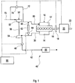
- Fig. 1 depicts schematically an example embodiment of an arrangement comprising a combustion engine 10 and an exhaust gas aftertreatment system 40 which is operated with a method according to the invention.
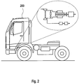
- Fig, 2 displays a vehicle 200 employing the method.
- the vehicle 200 is preferably a light, medium of heavy duty vehicle such as a truck.
- the engine 10 comprises an intake manifold 12 for air compressed by a compressor 52 of a turbocharger 50 and fed via air pipe 80 and an exhaust manifold 14 for discharging exhaust gases to a turbine 54 of the turbocharger 50 via an exhaust pipe 30 and the exhaust gas aftertreatment system 40.
- the turbine 54 can drive the compressor 52 through a common axle 56.
- a part of the exhaust gases can be recirculated from the exhaust manifold 14 to the intake manifold 12 by a recirculation pipe 60 comprising an exhaust gas cooler 62.
- the amount of recirculated exhaust gas can be adjusted by an exhaust gas recirculation valve 64 in the recirculation pipe 60 and an exhaust pressure governor valve 46 in an exhaust pipe 42 of the exhaust gas aftertreatment system 40.
- Exhaust gas is cleaned in a converter section 44 comprising for instance a NOx catalytic converter such as a selective catalytic reduction (SCR) unit, particulate filter, oxidation catalytic converter and the like as generally known in the art.
- a NOx catalytic converter such as a selective catalytic reduction (SCR) unit, particulate filter, oxidation catalytic converter and the like as generally known in the art.
- SCR selective catalytic reduction
- the compressor 52 can be bypassed by a discharge recirculation valve 74 (DRV) arranged in a bypass pipe 72 so that air from an inlet pipe 70 upstream of the compressor 52 can at least partially bypass the compressor 52 thus reducing the pressure in the intake manifold 12.
- DVR discharge recirculation valve 74
- the engine 10 drives a driveline 22 and is coupled to the driveline 22 via an output shaft 16 and a gearbox 20.
- a clutch 18 can be provided between the engine 10 and the gear box 20. the engine 10 can be couplet to or decoupled from the driveline 22 by the gearbox 20 or the clutch 18.
- a unit 90 can be provided for controlling the valves 46, 64, 74, optional clutch 18, gearbox 20 and fuel supply of engine 10.
- the unit 90 can comprise units such as computer processors and memory on which the method according to the invention is implemented.
- an exhaust gas temperature of the engine 10 is controlled during interruption of fuel supply to the engine 10.
- An interruption of fuel supply is triggered e.g. when the driver releases the gas pedal or another unit for requesting a torque from the engine 10 for propelling the vehicle.
- the method is alternating between an engine braking operational mode generating a first brake torque and an operational mode with exhaust gas recirculation generating a lower brake torque than the first brake torque.
- Fig. 3 depicts torque graphs as a function of rotational speed illustrating engine brake torques in engine modes with high, low and average brake torque according to the invention.
- Graph A illustrates a friction torque of the engine as a function of the rotational speed of the engine representing the brake power of the engine without fuel supply while the vehicle is moving, i.e. with friction braking of the engine.
- Graph B illustrates an example of a medium brake torque.
- a high brake torque denotes a high negative torque, for instance a torque in the range of -1500 Nm.
- a low brake torque denotes a low negative torque, for instance in the range of -200 Nm.
- a high brake torque refers to a high negative torque value.
- the lower brake torque T_lo can be provided by an operational mode with exhaust gas recirculation as this can be regulated with a very low gas flow through the exhaust gas aftertreatment system and hence maintaining a high temperature in the exhaust gas aftertreatment system as virtually no cooling gas flow occurs. It is a favourable strategy for keeping the temperature in the exhaust gas aftertreatment system high while the engine is not generating higher negative or positive torque to minimize the cold air gas flow through the engine and the exhaust gas aftertreatment system.
- the exhaust gas temperature may not be very high when the engine torque is low. Typically, at friction torque the exhaust gas temperature is about 100°C. At higher engine brake torque, e.g. above 1000 Nm, particularly around 1500 Nm, the exhaust gas temperature is higher, e.g. between 200°C and 400°C. and has little or no negative effect on the exhaust gas aftertreatment system concerning temperature.
- the exhaust gas temperature is very low and the mass flow through the exhaust gas aftertreatment system fairly high, while the brake torque T_hi is high.
- the desire brake torque T_av can be established with a high enough temperature to keep by way of example the particulate filter and the selective reduction catalytic converter operative in the exhaust gas aftertreatment system.
- the engine in another variant can be disengaged from the driveline in a first operational mode alternating with an engine compression brake operational mode for generating a brake torque.
- Fig. 4 and 5 display graphs related to this variant, wherein Fig. 4 shows graphs of an engine map for negative torques illustrating an exhaust temperature management during engine braking and Fig. 5 shows graphs of torque control by a discharge recirculation valve illustrating a behaviour of brake power and exhaust gas temperature using discharge recirculation.
- FIG. 4 The dependency of the engine torque on the engine rotational speed is shown by graphs C, D, E of Fig. 4 .
- S1, S2, S3 show constant engine speed at about 1000 rpm, 1300 rpm and 1600 rpm.
- Graph C depicts the brake torque by engine friction braking. The torque increases with increasing rotational speed.
- Graph E displays a brake torque with a maximum exhaust compression braking, which normally yields an exhaust temperature high enough for the maintaining the components in the exhaust gas aftertreatment system operative.
- Graph D shows a throttled exhaust compression braking.
- the point T_id at 600 rpm represents an idling engine with zero torque at e.g. 600 rpm.
- the temperature can be increased to a certain level or maintained on a high level by using for example an air inlet throttle which also reduces the mass flow. This can be done for short or medium idling operational modes.
- a reasonable time for keeping the temperatures of the exhaust gas aftertreatment system with the help of an inlet throttle is in the order of minutes, for instance between 0 - 10 minutes.
- the throttle may increase the exhaust gas temperature slightly but mainly reduces the mass flow through the exhaust gas aftertreatment system.
- the idling (or possibly shut off engine) operational mode can be alternated with a reduced exhaust compression braking operational mode, particularly on highest gear.
- This is exemplified by the torque T_C at 1000 rpm corresponding by way of example to 90 km/h.
- the temperature of the exhaust gas aftertreatment system can be maintained on a sufficiently high level for particulate filter and NOx catalytic converter operatable without providing a too high brake torque during idling.
- the engine can be decoupled from the driveline with the gear box in neutral position or at least freewheeling.
- DVT discharge recirculation valve
- Fig. 5 shows a brake power and temperature of the exhaust gas when using the discharge recirculation valve.
- the brake power is now shown as positive numbers.
- Graph F represents a baseline without activation of the discharge recirculation valve, Temp_F is the resulting temperature graph.
- the brake power increases strongly as a function of the rotational speed of the engine while the temperature of the exhaust gas varies between about 250°C and 350°C.
- the brake power is reduced from e.g. 250 kW at 1900 rpm (graph F) to below 200 kW as can be seen by graph G, whereas the temperature Temp_G is hardly changed in comparison to the deactivated discharge recirculation valve.
Landscapes
- Engineering & Computer Science (AREA)
- Chemical & Material Sciences (AREA)
- Combustion & Propulsion (AREA)
- Mechanical Engineering (AREA)
- General Engineering & Computer Science (AREA)
- Output Control And Ontrol Of Special Type Engine (AREA)
- Exhaust Gas After Treatment (AREA)
- Control Of Vehicle Engines Or Engines For Specific Uses (AREA)
- Control Of Throttle Valves Provided In The Intake System Or In The Exhaust System (AREA)
- Processes For Solid Components From Exhaust (AREA)
- Exhaust-Gas Circulating Devices (AREA)
- Combined Controls Of Internal Combustion Engines (AREA)
Applications Claiming Priority (1)
| Application Number | Priority Date | Filing Date | Title |
|---|---|---|---|
| PCT/SE2009/000154 WO2010110700A1 (en) | 2009-03-24 | 2009-03-24 | Method for controlling an exhaust gas temperature |
Publications (3)
| Publication Number | Publication Date |
|---|---|
| EP2411646A1 EP2411646A1 (en) | 2012-02-01 |
| EP2411646A4 EP2411646A4 (en) | 2018-01-17 |
| EP2411646B1 true EP2411646B1 (en) | 2020-07-08 |
Family
ID=42781231
Family Applications (1)
| Application Number | Title | Priority Date | Filing Date |
|---|---|---|---|
| EP09842390.8A Active EP2411646B1 (en) | 2009-03-24 | 2009-03-24 | Method for controlling an exhaust gas temperature |
Country Status (7)
| Country | Link |
|---|---|
| US (1) | US8849550B2 (enExample) |
| EP (1) | EP2411646B1 (enExample) |
| JP (1) | JP5325334B2 (enExample) |
| CN (1) | CN102365442B (enExample) |
| BR (1) | BRPI0924985B1 (enExample) |
| RU (1) | RU2490495C2 (enExample) |
| WO (1) | WO2010110700A1 (enExample) |
Cited By (1)
| Publication number | Priority date | Publication date | Assignee | Title |
|---|---|---|---|---|
| US12655806B2 (en) | 2023-11-30 | 2026-06-16 | Cummins Inc. | Engine braking mode selection systems and methods |
Families Citing this family (19)
| Publication number | Priority date | Publication date | Assignee | Title |
|---|---|---|---|---|
| US8950378B2 (en) * | 2012-05-11 | 2015-02-10 | Caterpiller Inc. | Retarding system |
| SE538100C2 (sv) * | 2012-09-27 | 2016-03-01 | Scania Cv Ab | Förfarande och system vid framförande av fordon |
| BR112015007438B1 (pt) * | 2012-10-02 | 2022-01-18 | Scania Cv Ab | Método para regulação de uma temperatura em um sistema de pós-tratamento de exaustão, sistema para controle de linha de transmissão, e veículo |
| DE112014000618T5 (de) | 2013-02-18 | 2015-10-22 | Cummins, Inc. | System, Verfahren und Vorrichtung zum Verwalten der Nachbehandlungstemperatur |
| JP5942972B2 (ja) * | 2013-12-18 | 2016-06-29 | 株式会社豊田自動織機 | 緊急車両の排気浄化システム |
| SE537663C2 (sv) * | 2014-01-15 | 2015-09-29 | Scania Cv Ab | Förfarande och system för styrning av temperatur för ett avgasbehandlingssystem |
| SE537928C2 (sv) * | 2014-01-15 | 2015-11-24 | Scania Cv Ab | Förfarande och system för styrning av temperatur för ett avgasbehandlingssystem |
| US9612174B2 (en) * | 2014-11-13 | 2017-04-04 | General Electric Corporation | Method and systems for exhaust gas recirculation valve diagnosis based on crankcase pressure |
| CN113482782A (zh) | 2015-01-19 | 2021-10-08 | 伊顿智能动力有限公司 | 柴油机发动机系统及其运行方法 |
| CN105888799B (zh) * | 2015-02-18 | 2020-01-17 | 福特环球技术公司 | 涉及排气后处理装置的方法 |
| US10605209B2 (en) * | 2015-10-28 | 2020-03-31 | Cummins Inc. | Thermal management via exhaust gas recirculation |
| US11199162B2 (en) | 2016-01-19 | 2021-12-14 | Eaton Intelligent Power Limited | In-cylinder EGR and VVA for aftertreatment temperature control |
| US10507834B2 (en) * | 2016-06-09 | 2019-12-17 | Ford Global Technologies, Llc | Cylinder deactivation control for driveline braking |
| US10576978B2 (en) * | 2017-12-06 | 2020-03-03 | Cummins, Inc. | System and method for predictive engine and aftertreatment system control |
| JP7444058B2 (ja) * | 2018-06-20 | 2024-03-06 | 株式会社アイシン | 弁開閉時期制御装置 |
| WO2020046718A1 (en) * | 2018-08-30 | 2020-03-05 | Achates Power, Inc. | Thermal management of exhaust gas aftertreatment devices of opposed-piston engines under motoring conditions |
| EP3899230B1 (en) * | 2018-12-20 | 2024-07-17 | Volvo Truck Corporation | A method for controlling the braking of a vehicle comprising a diesel engine |
| US10830191B1 (en) * | 2019-08-19 | 2020-11-10 | Caterpillar Inc. | Temperature management of an aftertreatment system during compression braking |
| CN117897318A (zh) * | 2021-09-07 | 2024-04-16 | 日产自动车株式会社 | 车辆的控制方法及车辆 |
Family Cites Families (23)
| Publication number | Priority date | Publication date | Assignee | Title |
|---|---|---|---|---|
| US5094206A (en) * | 1991-02-25 | 1992-03-10 | General Motors Corporation | Method for controlling a crankcase scavenged two-stroke engine during deceleration fuel cut-off |
| JP2582972B2 (ja) * | 1991-11-12 | 1997-02-19 | 日産自動車株式会社 | ディーゼル機関の排気還流装置 |
| RU2084670C1 (ru) * | 1994-01-11 | 1997-07-20 | Вениамин Михайлович Горюнов | Способ управления двигателем автомобиля |
| JP3230438B2 (ja) * | 1996-06-10 | 2001-11-19 | トヨタ自動車株式会社 | ハイブリッド型車両の触媒温度制御装置 |
| JPH11210507A (ja) | 1998-01-27 | 1999-08-03 | Nissan Motor Co Ltd | 可変動弁装置付き内燃機関の制御装置 |
| JP3883095B2 (ja) | 2000-02-04 | 2007-02-21 | 日産ディーゼル工業株式会社 | ブレーキ装置の制御方法 |
| JP2001271673A (ja) * | 2000-03-27 | 2001-10-05 | Mazda Motor Corp | エンジンの制御装置 |
| DE60212079T2 (de) * | 2001-02-20 | 2006-12-07 | Isuzu Motors Ltd. | Verfahren zur Steuerung der Kraftstoffeinspritzung für Dieselmotoren und Regenerationssteuerungsverfahren für Abgasnachbehandlungsvorrichtung |
| DE10118878A1 (de) * | 2001-04-18 | 2002-10-31 | Bosch Gmbh Robert | Verfahren zum Betreiben einer Brennkraftmaschine insbesondere eines Kraftfahrzeugs |
| SE523514C2 (sv) | 2001-11-30 | 2004-04-27 | Scania Cv Ab | Förfarande och anordning vid en förbränningsmotor med katalysator samt dieselmotor |
| JP4083478B2 (ja) * | 2002-06-25 | 2008-04-30 | トヨタ自動車株式会社 | 内燃機関 |
| DE10229035B4 (de) * | 2002-06-28 | 2015-10-15 | Robert Bosch Gmbh | Verfahren zur Steuerung der Antriebseinheit eines Fahrzeugs |
| JP3612711B2 (ja) * | 2002-07-03 | 2005-01-19 | トヨタ自動車株式会社 | 自動車 |
| US20040123588A1 (en) * | 2002-12-30 | 2004-07-01 | Stanglmaier Rudolf H. | Method for controlling exhaust gas temperature and space velocity during regeneration to protect temperature sensitive diesel engine components and aftertreatment devices |
| US20030178002A1 (en) | 2003-02-27 | 2003-09-25 | Israel Mark A. | Apparatus and method to operate an engine exhaust brake together with an exhaust gas recirculation system |
| DE102004052670A1 (de) | 2004-10-29 | 2006-05-04 | Daimlerchrysler Ag | Verfahren zum Betrieb einer Brennkraftmaschine im Motorbremsbetrieb |
| US7380396B2 (en) * | 2005-05-25 | 2008-06-03 | General Motors Corporation | Method for protecting an exhaust aftertreatment system |
| BRPI0520619B8 (pt) | 2005-09-15 | 2020-01-28 | Volvo Lastvagnar Ab | método para manter calor em um sistema de pós tratamento de exaustão |
| EP1826382B1 (en) * | 2006-02-24 | 2015-03-25 | Volvo Car Corporation | An internal combustion engine and a method for such an engine |
| GB0615495D0 (en) | 2006-08-04 | 2006-09-13 | Cummins Turbo Tech Ltd | Variable geometry turbine |
| US20080196388A1 (en) | 2007-02-21 | 2008-08-21 | Johnson Randall J | Method and apparatus for activating a diesel particulate filter with engine heat |
| JP4957374B2 (ja) * | 2007-05-15 | 2012-06-20 | いすゞ自動車株式会社 | 車両 |
| JP4973374B2 (ja) * | 2007-08-07 | 2012-07-11 | 日産自動車株式会社 | ハイブリッド原動機の制御装置 |
-
2009
- 2009-03-24 EP EP09842390.8A patent/EP2411646B1/en active Active
- 2009-03-24 JP JP2012501955A patent/JP5325334B2/ja not_active Expired - Fee Related
- 2009-03-24 BR BRPI0924985-0A patent/BRPI0924985B1/pt active IP Right Grant
- 2009-03-24 US US13/256,999 patent/US8849550B2/en active Active
- 2009-03-24 CN CN200980158323.0A patent/CN102365442B/zh not_active Expired - Fee Related
- 2009-03-24 RU RU2011142808/06A patent/RU2490495C2/ru active
- 2009-03-24 WO PCT/SE2009/000154 patent/WO2010110700A1/en not_active Ceased
Non-Patent Citations (1)
| Title |
|---|
| None * |
Cited By (1)
| Publication number | Priority date | Publication date | Assignee | Title |
|---|---|---|---|---|
| US12655806B2 (en) | 2023-11-30 | 2026-06-16 | Cummins Inc. | Engine braking mode selection systems and methods |
Also Published As
| Publication number | Publication date |
|---|---|
| BRPI0924985B1 (pt) | 2020-10-27 |
| JP2012521520A (ja) | 2012-09-13 |
| EP2411646A1 (en) | 2012-02-01 |
| JP5325334B2 (ja) | 2013-10-23 |
| BRPI0924985A2 (pt) | 2016-01-12 |
| EP2411646A4 (en) | 2018-01-17 |
| CN102365442A (zh) | 2012-02-29 |
| RU2011142808A (ru) | 2013-04-27 |
| CN102365442B (zh) | 2016-06-29 |
| US8849550B2 (en) | 2014-09-30 |
| WO2010110700A1 (en) | 2010-09-30 |
| RU2490495C2 (ru) | 2013-08-20 |
| US20120059572A1 (en) | 2012-03-08 |
Similar Documents
| Publication | Publication Date | Title |
|---|---|---|
| US8849550B2 (en) | Method for controlling an exhaust gas temperature | |
| US9670855B2 (en) | System, method, and apparatus for managing aftertreatment temperature | |
| US9840972B2 (en) | Supercharger-based twin charging system for an engine | |
| US7373933B2 (en) | Control apparatus and control method of vehicular driving apparatus | |
| CN109923293B (zh) | 在具有混合驱动装置的机动车中对颗粒过滤器进行再生的方法和设备 | |
| US9863352B2 (en) | Regulation of a temperature in an exhaust aftertreatment system | |
| JP4944273B2 (ja) | 車両においてギアシフトを実行する方法及び動力伝達装置 | |
| US11148654B2 (en) | Fast cold start heat up and energy efficiency for commercial vehicle powertrain | |
| CN106414947B (zh) | 用于在变速器自动换档事件期间控制电子控制的涡轮增压器的系统和方法 | |
| US20090301061A1 (en) | Limiting transmission function while in regeneration mode for a diesel particulate filter | |
| JP2009108808A (ja) | ハイブリッドシステムの制御装置 | |
| JPH11205907A (ja) | ハイブリッド車の駆動制御装置 | |
| JP2004100827A (ja) | 車両の油圧制御装置 | |
| JP2014159255A (ja) | ハイブリッド車両の制御装置 | |
| JP5891853B2 (ja) | 車両搭載のターボ過給機付エンジンの制御装置 | |
| US20160084149A1 (en) | Supercharger Assembly | |
| EP3161297B1 (en) | Internal combustion engine system with heat recovery | |
| EP2886828B1 (en) | Improved turbocompound system | |
| CN110486175A (zh) | 用于运行内燃机中的马达制动器的方法 | |
| JP5573795B2 (ja) | 内燃機関の排気浄化システム | |
| EP2923050B1 (en) | Regulation of a temperature in an exhaust aftertreatment system | |
| WO2008082466A1 (en) | Power system | |
| JP2021130328A (ja) | 車両およびその制御方法 |
Legal Events
| Date | Code | Title | Description |
|---|---|---|---|
| PUAI | Public reference made under article 153(3) epc to a published international application that has entered the european phase |
Free format text: ORIGINAL CODE: 0009012 |
|
| 17P | Request for examination filed |
Effective date: 20111024 |
|
| AK | Designated contracting states |
Kind code of ref document: A1 Designated state(s): AT BE BG CH CY CZ DE DK EE ES FI FR GB GR HR HU IE IS IT LI LT LU LV MC MK MT NL NO PL PT RO SE SI SK TR |
|
| DAX | Request for extension of the european patent (deleted) | ||
| RA4 | Supplementary search report drawn up and despatched (corrected) |
Effective date: 20171219 |
|
| RIC1 | Information provided on ipc code assigned before grant |
Ipc: F02D 13/04 20060101AFI20171213BHEP Ipc: F02D 17/02 20060101ALI20171213BHEP Ipc: F02D 41/00 20060101ALI20171213BHEP Ipc: F02M 26/05 20160101ALI20171213BHEP Ipc: F02D 41/02 20060101ALI20171213BHEP Ipc: F01N 3/10 20060101ALI20171213BHEP Ipc: F02D 41/12 20060101ALI20171213BHEP Ipc: F01L 13/06 20060101ALI20171213BHEP |
|
| GRAP | Despatch of communication of intention to grant a patent |
Free format text: ORIGINAL CODE: EPIDOSNIGR1 |
|
| STAA | Information on the status of an ep patent application or granted ep patent |
Free format text: STATUS: GRANT OF PATENT IS INTENDED |
|
| RIC1 | Information provided on ipc code assigned before grant |
Ipc: F02B 3/06 20060101ALI20200330BHEP Ipc: F02D 41/12 20060101ALI20200330BHEP Ipc: F02D 17/02 20060101ALI20200330BHEP Ipc: F01L 13/06 20060101ALI20200330BHEP Ipc: F02D 41/02 20060101ALI20200330BHEP Ipc: F02M 26/05 20160101ALI20200330BHEP Ipc: F02D 13/04 20060101AFI20200330BHEP Ipc: F01N 3/10 20060101ALI20200330BHEP Ipc: F02D 41/00 20060101ALI20200330BHEP |
|
| INTG | Intention to grant announced |
Effective date: 20200423 |
|
| GRAS | Grant fee paid |
Free format text: ORIGINAL CODE: EPIDOSNIGR3 |
|
| GRAA | (expected) grant |
Free format text: ORIGINAL CODE: 0009210 |
|
| STAA | Information on the status of an ep patent application or granted ep patent |
Free format text: STATUS: THE PATENT HAS BEEN GRANTED |
|
| AK | Designated contracting states |
Kind code of ref document: B1 Designated state(s): AT BE BG CH CY CZ DE DK EE ES FI FR GB GR HR HU IE IS IT LI LT LU LV MC MK MT NL NO PL PT RO SE SI SK TR |
|
| REG | Reference to a national code |
Ref country code: GB Ref legal event code: FG4D |
|
| RIN1 | Information on inventor provided before grant (corrected) |
Inventor name: ALM, CHRISTER Inventor name: BERNLER, HANS Inventor name: LARSSON, PER |
|
| REG | Reference to a national code |
Ref country code: CH Ref legal event code: EP Ref country code: AT Ref legal event code: REF Ref document number: 1288709 Country of ref document: AT Kind code of ref document: T Effective date: 20200715 |
|
| REG | Reference to a national code |
Ref country code: DE Ref legal event code: R096 Ref document number: 602009062393 Country of ref document: DE |
|
| REG | Reference to a national code |
Ref country code: IE Ref legal event code: FG4D |
|
| REG | Reference to a national code |
Ref country code: LT Ref legal event code: MG4D |
|
| REG | Reference to a national code |
Ref country code: AT Ref legal event code: MK05 Ref document number: 1288709 Country of ref document: AT Kind code of ref document: T Effective date: 20200708 |
|
| REG | Reference to a national code |
Ref country code: NL Ref legal event code: MP Effective date: 20200708 |
|
| PG25 | Lapsed in a contracting state [announced via postgrant information from national office to epo] |
Ref country code: BG Free format text: LAPSE BECAUSE OF FAILURE TO SUBMIT A TRANSLATION OF THE DESCRIPTION OR TO PAY THE FEE WITHIN THE PRESCRIBED TIME-LIMIT Effective date: 20201008 Ref country code: LT Free format text: LAPSE BECAUSE OF FAILURE TO SUBMIT A TRANSLATION OF THE DESCRIPTION OR TO PAY THE FEE WITHIN THE PRESCRIBED TIME-LIMIT Effective date: 20200708 Ref country code: ES Free format text: LAPSE BECAUSE OF FAILURE TO SUBMIT A TRANSLATION OF THE DESCRIPTION OR TO PAY THE FEE WITHIN THE PRESCRIBED TIME-LIMIT Effective date: 20200708 Ref country code: HR Free format text: LAPSE BECAUSE OF FAILURE TO SUBMIT A TRANSLATION OF THE DESCRIPTION OR TO PAY THE FEE WITHIN THE PRESCRIBED TIME-LIMIT Effective date: 20200708 Ref country code: PT Free format text: LAPSE BECAUSE OF FAILURE TO SUBMIT A TRANSLATION OF THE DESCRIPTION OR TO PAY THE FEE WITHIN THE PRESCRIBED TIME-LIMIT Effective date: 20201109 Ref country code: AT Free format text: LAPSE BECAUSE OF FAILURE TO SUBMIT A TRANSLATION OF THE DESCRIPTION OR TO PAY THE FEE WITHIN THE PRESCRIBED TIME-LIMIT Effective date: 20200708 Ref country code: NO Free format text: LAPSE BECAUSE OF FAILURE TO SUBMIT A TRANSLATION OF THE DESCRIPTION OR TO PAY THE FEE WITHIN THE PRESCRIBED TIME-LIMIT Effective date: 20201008 Ref country code: GR Free format text: LAPSE BECAUSE OF FAILURE TO SUBMIT A TRANSLATION OF THE DESCRIPTION OR TO PAY THE FEE WITHIN THE PRESCRIBED TIME-LIMIT Effective date: 20201009 Ref country code: SE Free format text: LAPSE BECAUSE OF FAILURE TO SUBMIT A TRANSLATION OF THE DESCRIPTION OR TO PAY THE FEE WITHIN THE PRESCRIBED TIME-LIMIT Effective date: 20200708 Ref country code: FI Free format text: LAPSE BECAUSE OF FAILURE TO SUBMIT A TRANSLATION OF THE DESCRIPTION OR TO PAY THE FEE WITHIN THE PRESCRIBED TIME-LIMIT Effective date: 20200708 |
|
| PG25 | Lapsed in a contracting state [announced via postgrant information from national office to epo] |
Ref country code: LV Free format text: LAPSE BECAUSE OF FAILURE TO SUBMIT A TRANSLATION OF THE DESCRIPTION OR TO PAY THE FEE WITHIN THE PRESCRIBED TIME-LIMIT Effective date: 20200708 Ref country code: PL Free format text: LAPSE BECAUSE OF FAILURE TO SUBMIT A TRANSLATION OF THE DESCRIPTION OR TO PAY THE FEE WITHIN THE PRESCRIBED TIME-LIMIT Effective date: 20200708 Ref country code: IS Free format text: LAPSE BECAUSE OF FAILURE TO SUBMIT A TRANSLATION OF THE DESCRIPTION OR TO PAY THE FEE WITHIN THE PRESCRIBED TIME-LIMIT Effective date: 20201108 |
|
| PG25 | Lapsed in a contracting state [announced via postgrant information from national office to epo] |
Ref country code: NL Free format text: LAPSE BECAUSE OF FAILURE TO SUBMIT A TRANSLATION OF THE DESCRIPTION OR TO PAY THE FEE WITHIN THE PRESCRIBED TIME-LIMIT Effective date: 20200708 |
|
| REG | Reference to a national code |
Ref country code: DE Ref legal event code: R097 Ref document number: 602009062393 Country of ref document: DE |
|
| PG25 | Lapsed in a contracting state [announced via postgrant information from national office to epo] |
Ref country code: IT Free format text: LAPSE BECAUSE OF FAILURE TO SUBMIT A TRANSLATION OF THE DESCRIPTION OR TO PAY THE FEE WITHIN THE PRESCRIBED TIME-LIMIT Effective date: 20200708 Ref country code: DK Free format text: LAPSE BECAUSE OF FAILURE TO SUBMIT A TRANSLATION OF THE DESCRIPTION OR TO PAY THE FEE WITHIN THE PRESCRIBED TIME-LIMIT Effective date: 20200708 Ref country code: EE Free format text: LAPSE BECAUSE OF FAILURE TO SUBMIT A TRANSLATION OF THE DESCRIPTION OR TO PAY THE FEE WITHIN THE PRESCRIBED TIME-LIMIT Effective date: 20200708 Ref country code: CZ Free format text: LAPSE BECAUSE OF FAILURE TO SUBMIT A TRANSLATION OF THE DESCRIPTION OR TO PAY THE FEE WITHIN THE PRESCRIBED TIME-LIMIT Effective date: 20200708 Ref country code: RO Free format text: LAPSE BECAUSE OF FAILURE TO SUBMIT A TRANSLATION OF THE DESCRIPTION OR TO PAY THE FEE WITHIN THE PRESCRIBED TIME-LIMIT Effective date: 20200708 |
|
| PLBE | No opposition filed within time limit |
Free format text: ORIGINAL CODE: 0009261 |
|
| STAA | Information on the status of an ep patent application or granted ep patent |
Free format text: STATUS: NO OPPOSITION FILED WITHIN TIME LIMIT |
|
| 26N | No opposition filed |
Effective date: 20210409 |
|
| PG25 | Lapsed in a contracting state [announced via postgrant information from national office to epo] |
Ref country code: SK Free format text: LAPSE BECAUSE OF FAILURE TO SUBMIT A TRANSLATION OF THE DESCRIPTION OR TO PAY THE FEE WITHIN THE PRESCRIBED TIME-LIMIT Effective date: 20200708 |
|
| PG25 | Lapsed in a contracting state [announced via postgrant information from national office to epo] |
Ref country code: SI Free format text: LAPSE BECAUSE OF FAILURE TO SUBMIT A TRANSLATION OF THE DESCRIPTION OR TO PAY THE FEE WITHIN THE PRESCRIBED TIME-LIMIT Effective date: 20200708 |
|
| PG25 | Lapsed in a contracting state [announced via postgrant information from national office to epo] |
Ref country code: MC Free format text: LAPSE BECAUSE OF FAILURE TO SUBMIT A TRANSLATION OF THE DESCRIPTION OR TO PAY THE FEE WITHIN THE PRESCRIBED TIME-LIMIT Effective date: 20200708 |
|
| REG | Reference to a national code |
Ref country code: CH Ref legal event code: PL |
|
| GBPC | Gb: european patent ceased through non-payment of renewal fee |
Effective date: 20210324 |
|
| REG | Reference to a national code |
Ref country code: BE Ref legal event code: MM Effective date: 20210331 |
|
| PG25 | Lapsed in a contracting state [announced via postgrant information from national office to epo] |
Ref country code: CH Free format text: LAPSE BECAUSE OF NON-PAYMENT OF DUE FEES Effective date: 20210331 Ref country code: LI Free format text: LAPSE BECAUSE OF NON-PAYMENT OF DUE FEES Effective date: 20210331 Ref country code: LU Free format text: LAPSE BECAUSE OF NON-PAYMENT OF DUE FEES Effective date: 20210324 Ref country code: GB Free format text: LAPSE BECAUSE OF NON-PAYMENT OF DUE FEES Effective date: 20210324 Ref country code: IE Free format text: LAPSE BECAUSE OF NON-PAYMENT OF DUE FEES Effective date: 20210324 Ref country code: FR Free format text: LAPSE BECAUSE OF NON-PAYMENT OF DUE FEES Effective date: 20210331 |
|
| PG25 | Lapsed in a contracting state [announced via postgrant information from national office to epo] |
Ref country code: BE Free format text: LAPSE BECAUSE OF NON-PAYMENT OF DUE FEES Effective date: 20210331 |
|
| PG25 | Lapsed in a contracting state [announced via postgrant information from national office to epo] |
Ref country code: HU Free format text: LAPSE BECAUSE OF FAILURE TO SUBMIT A TRANSLATION OF THE DESCRIPTION OR TO PAY THE FEE WITHIN THE PRESCRIBED TIME-LIMIT; INVALID AB INITIO Effective date: 20090324 Ref country code: CY Free format text: LAPSE BECAUSE OF FAILURE TO SUBMIT A TRANSLATION OF THE DESCRIPTION OR TO PAY THE FEE WITHIN THE PRESCRIBED TIME-LIMIT Effective date: 20200708 |
|
| PG25 | Lapsed in a contracting state [announced via postgrant information from national office to epo] |
Ref country code: MK Free format text: LAPSE BECAUSE OF FAILURE TO SUBMIT A TRANSLATION OF THE DESCRIPTION OR TO PAY THE FEE WITHIN THE PRESCRIBED TIME-LIMIT Effective date: 20200708 |
|
| PG25 | Lapsed in a contracting state [announced via postgrant information from national office to epo] |
Ref country code: TR Free format text: LAPSE BECAUSE OF FAILURE TO SUBMIT A TRANSLATION OF THE DESCRIPTION OR TO PAY THE FEE WITHIN THE PRESCRIBED TIME-LIMIT Effective date: 20200708 |
|
| PG25 | Lapsed in a contracting state [announced via postgrant information from national office to epo] |
Ref country code: MT Free format text: LAPSE BECAUSE OF FAILURE TO SUBMIT A TRANSLATION OF THE DESCRIPTION OR TO PAY THE FEE WITHIN THE PRESCRIBED TIME-LIMIT Effective date: 20200708 |
|
| PGFP | Annual fee paid to national office [announced via postgrant information from national office to epo] |
Ref country code: DE Payment date: 20260320 Year of fee payment: 18 |