EP2411303B1 - Spender zur darreichung von plättchenförmigen stoffen - Google Patents
Spender zur darreichung von plättchenförmigen stoffen Download PDFInfo
- Publication number
- EP2411303B1 EP2411303B1 EP10716756A EP10716756A EP2411303B1 EP 2411303 B1 EP2411303 B1 EP 2411303B1 EP 10716756 A EP10716756 A EP 10716756A EP 10716756 A EP10716756 A EP 10716756A EP 2411303 B1 EP2411303 B1 EP 2411303B1
- Authority
- EP
- European Patent Office
- Prior art keywords
- lid
- housing
- dispenser according
- removal opening
- platelet
- Prior art date
- Legal status (The legal status is an assumption and is not a legal conclusion. Google has not performed a legal analysis and makes no representation as to the accuracy of the status listed.)
- Not-in-force
Links
- 239000000126 substance Substances 0.000 title claims description 71
- 125000006850 spacer group Chemical group 0.000 claims description 23
- 240000007817 Olea europaea Species 0.000 claims description 9
- 230000002093 peripheral effect Effects 0.000 claims 1
- 230000036316 preload Effects 0.000 claims 1
- 238000005452 bending Methods 0.000 description 22
- 239000000463 material Substances 0.000 description 14
- 239000003814 drug Substances 0.000 description 6
- 241000196324 Embryophyta Species 0.000 description 4
- 239000002274 desiccant Substances 0.000 description 4
- 229940079593 drug Drugs 0.000 description 4
- 239000002537 cosmetic Substances 0.000 description 3
- 239000003205 fragrance Substances 0.000 description 3
- 238000004519 manufacturing process Methods 0.000 description 3
- 238000000034 method Methods 0.000 description 3
- 239000004480 active ingredient Substances 0.000 description 2
- 235000015872 dietary supplement Nutrition 0.000 description 2
- 238000001746 injection moulding Methods 0.000 description 2
- 239000004033 plastic Substances 0.000 description 2
- 238000003466 welding Methods 0.000 description 2
- 238000004026 adhesive bonding Methods 0.000 description 1
- 239000002830 appetite depressant Substances 0.000 description 1
- 244000052616 bacterial pathogen Species 0.000 description 1
- 239000011324 bead Substances 0.000 description 1
- 150000001875 compounds Chemical class 0.000 description 1
- 235000009508 confectionery Nutrition 0.000 description 1
- 238000010276 construction Methods 0.000 description 1
- 238000011109 contamination Methods 0.000 description 1
- 239000003433 contraceptive agent Substances 0.000 description 1
- 229940124558 contraceptive agent Drugs 0.000 description 1
- 238000011161 development Methods 0.000 description 1
- 230000018109 developmental process Effects 0.000 description 1
- 201000010099 disease Diseases 0.000 description 1
- 208000037265 diseases, disorders, signs and symptoms Diseases 0.000 description 1
- 238000006073 displacement reaction Methods 0.000 description 1
- 239000002552 dosage form Substances 0.000 description 1
- 238000012377 drug delivery Methods 0.000 description 1
- 230000000694 effects Effects 0.000 description 1
- 230000005489 elastic deformation Effects 0.000 description 1
- 239000003792 electrolyte Substances 0.000 description 1
- -1 flavorings Substances 0.000 description 1
- 239000005556 hormone Substances 0.000 description 1
- 229940088597 hormone Drugs 0.000 description 1
- 239000003326 hypnotic agent Substances 0.000 description 1
- 230000000147 hypnotic effect Effects 0.000 description 1
- 238000002347 injection Methods 0.000 description 1
- 239000007924 injection Substances 0.000 description 1
- 238000005304 joining Methods 0.000 description 1
- 239000007788 liquid Substances 0.000 description 1
- 239000002991 molded plastic Substances 0.000 description 1
- 210000004877 mucosa Anatomy 0.000 description 1
- 239000006186 oral dosage form Substances 0.000 description 1
- 239000000123 paper Substances 0.000 description 1
- 230000035515 penetration Effects 0.000 description 1
- 239000002304 perfume Substances 0.000 description 1
- 239000006187 pill Substances 0.000 description 1
- 238000002360 preparation method Methods 0.000 description 1
- 239000000047 product Substances 0.000 description 1
- 238000007789 sealing Methods 0.000 description 1
- 239000000344 soap Substances 0.000 description 1
- 230000000475 sunscreen effect Effects 0.000 description 1
- 239000000516 sunscreening agent Substances 0.000 description 1
- 235000013343 vitamin Nutrition 0.000 description 1
- 239000011782 vitamin Substances 0.000 description 1
- 229940088594 vitamin Drugs 0.000 description 1
- 229930003231 vitamin Natural products 0.000 description 1
- 230000002087 whitening effect Effects 0.000 description 1
Images





Classifications
-
- B—PERFORMING OPERATIONS; TRANSPORTING
- B65—CONVEYING; PACKING; STORING; HANDLING THIN OR FILAMENTARY MATERIAL
- B65D—CONTAINERS FOR STORAGE OR TRANSPORT OF ARTICLES OR MATERIALS, e.g. BAGS, BARRELS, BOTTLES, BOXES, CANS, CARTONS, CRATES, DRUMS, JARS, TANKS, HOPPERS, FORWARDING CONTAINERS; ACCESSORIES, CLOSURES, OR FITTINGS THEREFOR; PACKAGING ELEMENTS; PACKAGES
- B65D83/00—Containers or packages with special means for dispensing contents
- B65D83/08—Containers or packages with special means for dispensing contents for dispensing thin flat articles in succession
- B65D83/0805—Containers or packages with special means for dispensing contents for dispensing thin flat articles in succession through an aperture in a wall
- B65D83/0811—Containers or packages with special means for dispensing contents for dispensing thin flat articles in succession through an aperture in a wall with means for assisting dispensing
- B65D83/0823—Containers or packages with special means for dispensing contents for dispensing thin flat articles in succession through an aperture in a wall with means for assisting dispensing the articles being pushed and slid through the aperture
- B65D83/0829—Containers or packages with special means for dispensing contents for dispensing thin flat articles in succession through an aperture in a wall with means for assisting dispensing the articles being pushed and slid through the aperture by means of an actuator
-
- B—PERFORMING OPERATIONS; TRANSPORTING
- B65—CONVEYING; PACKING; STORING; HANDLING THIN OR FILAMENTARY MATERIAL
- B65D—CONTAINERS FOR STORAGE OR TRANSPORT OF ARTICLES OR MATERIALS, e.g. BAGS, BARRELS, BOTTLES, BOXES, CANS, CARTONS, CRATES, DRUMS, JARS, TANKS, HOPPERS, FORWARDING CONTAINERS; ACCESSORIES, CLOSURES, OR FITTINGS THEREFOR; PACKAGING ELEMENTS; PACKAGES
- B65D83/00—Containers or packages with special means for dispensing contents
- B65D83/08—Containers or packages with special means for dispensing contents for dispensing thin flat articles in succession
- B65D83/0847—Containers or packages with special means for dispensing contents for dispensing thin flat articles in succession through an aperture at the junction of two walls
- B65D83/0852—Containers or packages with special means for dispensing contents for dispensing thin flat articles in succession through an aperture at the junction of two walls with means for assisting dispensing
- B65D83/0864—Containers or packages with special means for dispensing contents for dispensing thin flat articles in succession through an aperture at the junction of two walls with means for assisting dispensing the articles being pushed and slid through the aperture
- B65D83/087—Containers or packages with special means for dispensing contents for dispensing thin flat articles in succession through an aperture at the junction of two walls with means for assisting dispensing the articles being pushed and slid through the aperture by means of an actuator
Definitions
- the invention relates to a dispenser for delivering platelet-shaped substances, comprising a housing, wherein the housing has a cavity for supporting a stack of platelet-shaped substances, wherein the housing forms a removal opening for the platelet-shaped substances, which can be opened and closed again by a lid, wherein the lid is connected to the housing and wherein the lid is connected to a conveyor bracket, which is movable together with the cover for conveying the platelet-shaped substances.
- the platelet-shaped substances are usually edible, water-soluble platelets for oral or other care. Platelet-shaped substances which are formed as medicaments, dietary supplements, sweets, cosmetics or hygiene articles are known. The platelet-shaped substances are often precut into regular rectangles and stored in a stack within the housing.
- the platelet-shaped substances are usually removed from the housing through a removal opening.
- the removal openings are often relatively small and the platelet-shaped substances are therefore removed only with difficulty.
- the US 2005/0 092 763 A1 discloses against this background, a dispenser that can be opened by moving a lid.
- the platelet-shaped substances are pressed by a survey in the direction of the removal opening so that they can be removed.
- the platelet-like substances are often film-like, water-soluble platelets that are relatively sensitive to moisture. It is particularly problematic that the platelet-shaped substances absorb moisture after some time and thereby decompose and stick together.
- a moisture-sealed dispenser describes the WO 2005/051 822 A1 , This has a conveyor bracket, which rests with the housing closed on the stack of platelet-shaped substances. As a result, however, the sensitive platelet-shaped substances can be pressed against each other and stick together.
- the US 2005/0 274 733 A1 addresses this problem with a dispenser, which leads the platelet-shaped substances by a sliding process out of the housing.
- the donor has this one Conveyor bar, which rests with the housing closed on the stack of platelet-shaped substances. As a result, however, the platelet-shaped substances can be pressed against each other and stick together.
- Another donor is from the FR 2 879 573 known.
- the invention is therefore based on the object, a dispenser of the type mentioned in such a way and further that this allows a contamination-free and reliable promotion of a single platelet-shaped substance from the interior of the housing solely by movement of the lid.
- a dispenser of the type mentioned is characterized in that the conveyor bracket is resiliently biased and is mounted in the housing, that it is spaced from the stack with the removal opening closed.
- a conveyor bracket allows a platelet-shaped material to be conveyed out of the interior of the housing from the removal opening without having to grasp the inside of the housing with fingers. It has also been recognized that a delivery bow that is under elastic prestressing can be subjected to a force such that it subtracts individual platelets or a single platelet-shaped substance from a stack and conveys them to the removal opening. Furthermore, it has been recognized that the fingers only have to touch the lid to move the conveyor bracket and thus a plate-like material. The interior of the housing is therefore not contaminated. Finally, it has been recognized that a conveyor bracket spaced from the stack does not press the platelet-shaped substances against one another and thereby prevents the substances from sticking together. In that regard, a dispenser is specified, which realizes a contamination-free and reliable promotion of individual platelet-shaped substances to a removal opening of the donor.
- the conveyor bracket could rest on a spacer for spacing from the stack when the removal opening is closed. This ensures that the conveyor bracket does not apply pressure to the platelet-shaped substances when the housing is closed. It is ensured that the platelet-shaped substances are not pressed against each other and can stick together.
- the delivery stirrup could execute a delivery stroke for taking along and conveying a platelet-shaped substance from the stack to the removal opening.
- the platelet-shaped material can be brought out of the interior of the housing in such a way to the removal opening solely by actuation of the cover, that the platelet-shaped material partially protrudes from the removal opening.
- the person operating the dispenser can therefore grasp the platelet-shaped substance with their fingers without contaminating the platelet-shaped substances remaining in the cavity of the housing.
- the conveyor bracket could at least partially move under a guideway during the delivery stroke.
- the conveyor bracket By moving the conveyor bracket under a ramp-like guideway, he can contact the top plate-like material of the stack with a rounded, bead-like contact surface and take it to the removal opening.
- the conveyor bracket could travel under a defined opening position of the lid a catch to come to a start end of the guideway to the plant.
- this specific embodiment of the conveyor bracket undercuts an elastically deformable detent such that it jumps from the end of the conveyor bracket after an elastic deformation in its rest position. As a result, the conveyor bracket can not return to the already traveled path.
- the catch blocks the conveyor track the path covered.
- the elastically deformable catch works in this specific embodiment in analogy to a check valve. After driving under the catch of the conveyor bracket comes to a start end of a ramp-like guideway to the plant.
- the conveyor bracket When the removal opening is closed, the conveyor bracket could be guided on a guideway within the housing such that it passes without contact through the stack of platelet-shaped substances.
- the lid of the conveyor bracket When closing the lid of the conveyor bracket is guided on the ramp-like guideway and sets a path that lies above the path that performs the conveyor bracket when opening the lid. Due to the guide on the ramp-like guideway of the conveyor bracket is spaced from the stack of platelet-shaped substances and has no contact with this. This avoids that the conveyor bracket collapses, upsets, folds or crumples the platelet-shaped substances remaining in the housing.
- the guide could be designed as a ramp, which is formed from a latched in the housing component.
- the component can be made separately from the housing and locked in this captive. This makes it possible to design guideways of different gradients and lengths regardless of the housing.
- the component includes a desiccant or is made of a desiccant compound. The desiccant absorbs liquid that has entered the housing.
- the component is also called a tray.
- the conveyor bracket could jump when closing the removal opening due to its elastic bias of a traversing the guideway on a spacer, the lid closes the housing.
- the lid can be force applied to the housing sealingly.
- the elastic Deformable conveyor arms deploy a restoring force, which is used to tighten the lid against the housing.
- the conveyor bracket could be formed as an elastically deformable body from which protrude on both sides side arms.
- the design as an elastically deformable body allows flexible bending of the conveyor bracket during the opening process and during the closing process.
- bending aids can be configured in the housing, which bend the conveyor bracket when opening and closing the lid.
- Projecting side arms make it possible to guide the conveyor bar under curvature on a guideway.
- the side arms can be guided on the guideway, wherein a main branch transmits the tensile force or the thrust of the moving lid on the side arms.
- the lid and the conveyor bracket could be integrally formed, wherein the lid is connected via clamping cam with the housing.
- the clamping cams allow to manufacture the lid separately and to connect with the housing captive.
- the integrally formed with the conveyor bracket lid could be made of a softer material than the housing. As a result, the lid when pressed against the housing unfold a very good sealing effect. The penetration of moisture into the interior of the housing is prevented. It is also conceivable that the lid is made of two components, in particular by 2-K injection molding.
- the clamping cams could be integrally formed with a rigid part to which the lid is pivotally connected via a film hinge.
- the conveyor bracket can be moved by pivoting the lid.
- the elastically deformable conveyor bracket follows guided by bending aids the curved path of the lid when opening and closing, namely when pivoting about the film hinge.
- the lid performs a translational movement when opening and closing the removal opening.
- the lid can be pulled away in the sense of a drawer from the housing or pushed into this.
- a dispenser with this concrete design is extremely flat and is characterized by a high degree of compactness.
- the lid could have a circumferential seal on the side which faces the removal opening. The seal ensures that the removal opening is moisture-tight or airtight when the lid is closed.
- a dispenser of this embodiment can accommodate moisture sensitive drugs, cosmetics, orally administrable fragrances or toiletries.
- the donor can take active ingredient platelets, which dissolve in the mouth by moisture in the short term, but are permanently storable in the donor. For this purpose, a desiccant may be added inside the dispenser.
- the seal could be designed as an olive seal.
- An olive seal has a convex bead which snaps or snaps into a concave groove. By an olive seal, the lid can be solved only with effort from the housing. The olive seal is just not flat, but runs inside the case.
- the dispenser could be constructed in three parts, namely consist of three individual parts, which are each injection-molded separately.
- the donor is easy to finished and has a small number of items that need to be locked or pressed together.
- the dispenser described here may e.g. tooth whitening preparations, nutritional supplements, vitamins, flavorings, fragrances, perfumes, hypnotics, contraceptives, hormones, appetite suppressants, medicines, orally administrable fragrances and electrolytes for athletes.
- the dispenser can be used to contain skin care products in the tropics, especially sunscreen.
- the dispenser may also contain soap, cosmetics, paper, especially business cards, or household items.
- the dispenser described here can receive and deliver almost all the thin platelets which are stacked in the housing of the dispenser can be accommodated.
- the platelets preferably have a width of 23 mm and a length of 28 mm.
- the dispenser described here is characterized by a very high compactness and fits, for example, in trouser pockets or handbags. Furthermore, it is easy to handle, since merely by opening the lid, a platelet-shaped material is conveyed.
- the people who can not swallow pills, platelet-shaped substances can be administered orally.
- the dispenser allows a very good oral dosage form for children and the elderly.
- the platelet-shaped substances allow rapid drug delivery through the mucosa. It is conceivable to equip the dispenser with a child safety device.
- the dispenser described here allows a cost-effective dosage form and can transport up to 65 mg of active ingredients.
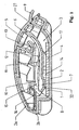
- Fig. 1 shows a dispenser for the presentation of platelet-shaped substances 1, comprising a housing 2, wherein the housing 2 has a cavity 3 for supporting a stack 4 of the platelet-like substances 1, wherein the housing 2 forms a removal opening 5 for the platelet-shaped substances 1, which by a Cover 6 can be opened and closed again, and wherein the lid 6 is connected to the housing 2.
- the lid 6 is connected to a conveyor bracket 7, which is movable together with the lid 6 for conveying the platelet-shaped substances 1.
- the conveyor bracket 7 is resiliently biased and mounted in the housing 2 such that it is spaced from the stack 4 when the housing 2 is closed or the removal opening 5 is closed.
- the conveyor bracket 7 rests with the lid closed 6 for spacing from the stack 4 on a spacer 8.
- the spacer 8 is formed as a spacer bevel.
- a handle 9 for gripping the lid 6 is formed on the lid 6, a handle 9 for gripping the lid 6 is formed.
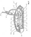
- Fig. 2 shows a sectional view of the dispenser according to Fig. 1 with open lid 6.
- the conveyor bracket 7 performs when opening the lid 6 a delivery stroke for taking and promotion of the platelet-shaped substance 1 from the stack 4 to the removal opening 5 from.
- the on the opening of the lid 6 to the removal opening by the conveyor bracket 7 advanced platelet-shaped material 1 protrudes from the removal opening 5 and can be grasped with fingers.
- the conveyor bracket 7 is hinged to the cover 6 such that it substantially prevents engagement with the removal opening 5 with fingers.
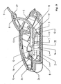
- Fig. 3 shows a sectional view of the dispenser according to Fig. 1 in which the lid 6 performs a closing movement.
- the conveyor bracket 7 is guided on the guide track 10 within the housing 2 in such a way that it passes without contact through the stack 4 of the platelet-shaped substances 1 and is moved over it at a distance.
- the conveyor bracket 7 is curved standing by a first bending aid 13 and the guide track 10 under elastic bias.
- the guideway 10 is formed as a ramp and formed on a latched in the housing 2 component 14.
- the component 14 is also referred to as a tray.
- the conveyor bracket 7 jumps when closing the lid 6 due to the curvature and its elastic bias of a traversing end 15 of the guide rail 10 on the spacer 8, wherein the cover 6 closes the housing 2.
- the conveyor bracket 7 is guided by a second bending aid 16 down on the spacer 8.
- the lid 6 performs during opening and closing of the removal opening 5 a pivoting movement.
- opening the lid 6 of the elastically deformable conveyor bracket 7 is curved by the first bending aid 13 and a third bending aid 17, the third bending aid 17 leads the conveyor bracket 7 to a stop 18.
- closing the lid 6 of the elastically deformable conveyor bracket 7 is through the first bending aid 13 and the ramp-like guideway 10 are curved.
- the second bending aid 16 forces the under elastic prestressing conveyor bracket 7 on the spacer 8 when closing the lid 6.
- the stopper 18 prevents the elastic conveyor bracket 7 is pulled out when opening the lid 6 over a defined extension position out of the housing 2.
- Fig. 4 shows in a perspective view of the housing 2 of the dispenser according to the Fig. 1 to 3 ,
- the housing 2 is injection-molded from plastic and consists of an upper part 2a and a lower part 2b.
- the upper part 2a and the lower part 2b are pivotally hinged together by a connecting web 19, which is formed as a film hinge.
- the removal opening 5 is formed, which can be penetrated by the conveyor bracket 7.
- the upper part 2a further has the first bending aid 13, which is designed as a substantially L-shaped, U-shaped or hook-shaped curved tongue. In this case, the end of the tongue protrudes in the direction of the removal opening 5.
- two component holders 2c, 2d for holding the component 14 are formed in the upper part 2a on both sides.
- the third bending aid 17 is formed in the lower part 2b.
- the stop 18 connects.
- the third bending aid 17 and the stop 18 are arranged on two sides of the lower part 2b.
- the spacer 8 formed as a spacer is further formed.
- the spacer 8 is formed as a two-stage pitch with two different curved inclined steps.
- a platelet guide 31 is further formed.
- the plate guide 31 is designed like a ramp and guides the platelet-shaped substances 1 to the removal opening 5.
- In the lower part 2b are further formed from two sides web-like projections 2e, on which the component 14 can be placed.
- the housing 2 is designed so that it can be removed from the mold without a slide from an injection mold.
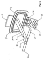
- Fig. 5 shows a perspective view of the lid 6, which is integrally formed with the conveyor bracket 7.
- the conveyor bracket 7 is formed as an elastically deformable body, from which on both sides side arms 20, 21 protrude.
- the side arms 20, 21 protrude from the end 22 of the conveyor bracket 7.
- the lid 6 is pressed by clamping cam 23 with the housing 2. Concretely, four clamping cams 23 engage in four receptacles 24 for the clamping cams 23 in the upper part 2a.
- the lid 6 is therefore captively connected to the upper part 2a of the housing 2.
- the clamping cams 23 are integrally formed with a rigid part 25 to which the lid 6 is pivotally connected via a film hinge 26.
- the cover 6 has a seal 27 which extends around the removal opening 5 on its side.
- the seal 27 is formed as an olive seal.
- the conveyor bracket 7 has a main branch 28 which is elastically deformed and curved by the first bending aid 13 and the third bending aid 17.
- the second bending aid 16 forces the end 22 of the conveyor bracket 7, from which the side arms 20, 21 protrude, on the spacer 8.
- the side arms 20, 21 are guided on the ramp-like guideway 10.
- the conveyor bracket 7 has at its end 22 a bead-like, curved contact surface 32, which comes into contact with the platelet-shaped substances 1 when they are taken.
- cover 6 it is also conceivable to produce the cover 6 by 2-K injection molding or in two parts from different components.
- Fig. 6 shows the component 14, which is locked to the lower part 2b of the housing 2 by mounting members 29 which are configured as recesses.
- the component 14 further has fork-like centering aids 30, which surround bar-like projections 2e in the lower part 2b of the housing 2.
- the mounting keys 29 and the centering aids 30 are formed on two sides of the component 14.
- the component 14 further has the ramp-like guide track 10 on which the side arms 20, 21 of the conveyor bracket 7 are guided.
- a part of the guideway 10 is the detent 11, which is designed as an elastically deformable tongue.
- the catch 11 has a starting end 12 of the guide track 10, via which the side arms 20, 21 of the conveyor bracket 7 are guided on the guide track 10. By this guide the side arms 20, 21 of the conveyor bracket 7 is guided past the stack 4 without contact.
- the second bending aid 16 is further formed on the component 14, which forces the end 22 of the conveyor bracket 7, from which the side arms 20, 21 protrude, onto the spacer 8.
- Fig. 7 shows an exploded perspective view of the three items from which the dispenser according to Fig. 1 is made.
- the injection-molded plastic component 14 the tray
- the lower part 2b is filled with the platelet-shaped substances 1.
- the cover 6 is pressed with the clamping cam 23 in the upper part 2a.
- the conveyor bracket 7 must be mounted under bias, so that he enough pressure on the platelet-shaped substances 1 to the Take along and promote. When mounting the lid 6, the conveyor bracket 7 is placed on the guideway 10.
- the upper part 2a is connected to the lower part 2b.
- this assembly step is to ensure that the conveyor bracket 7 does not slip off the guideway 10.
- the conveyor bracket 7 jumps on the spacer 8.
- the dispenser is fully assembled and provided for the presentation of the platelet-shaped substances 1. After each promotion of a platelet-shaped substance 1 of the conveyor bracket 7 jumps when closing the lid 6 on the spacer 8 back to start from there again when the lid 6 is opened.
- the elastic bias of the conveyor bracket 7, with which it contacts the stack 4 is to be selected such that it also promotes the last remaining on the stack 4 platelet-shaped material 1 still reliable to the removal opening 5.
- Fig. 8 shows a perspective view of the dispenser with lid open 6. From the removal opening 5 protrudes a platelet-shaped substance 1 in the form of a platelet.
- the conveyor bracket 7 passes through the removal opening 5 such that it is extremely difficult to intervene in the interior of the housing 2 with fingers. Contamination of the platelet-shaped substances 1 in the interior of the housing 2 is thereby effectively avoided.
- the olive seal 27 on the lid 6 seals the housing 2 liquid-tight and gas-tight against the atmosphere.
- Fig. 9 shows three views of the closed dispenser according to Fig. 1 ,
- the view top left in Fig. 9 shows a view of the lid 6 in the direction of the longitudinal axis of the housing 2.
- the top right view in Fig. 9 shows a side view of the dispenser.
- the view in the lower right in Fig. 9 shows a plan view of the lid 6 of the dispenser.
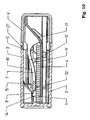
- Fig. 10 shows a further embodiment of a dispenser for the presentation of platelet-like substances 1, comprising a housing 2 ', wherein the housing 2' has a cavity 3 'for supporting a stack 4 of the plate-like substances 1, wherein the housing 2' a removal opening 5 'for the platelet-shaped substances 1 forms, which can be opened and reclosed by a lid 6 ', and wherein the lid 6' with the housing 2 'is connected.
- the lid 6 ' is connected to a conveyor bracket 7', which together with the cover 6 'for conveying the platelet-shaped substances 1 is movable.
- the conveyor bracket 7 ' is resiliently biased and mounted in the housing 2' such that it is spaced from the stack 4 when the housing 2 'is closed or the removal opening 5 is closed.
- the conveyor bracket 7 rests with the lid closed 6' for spacing from the stack 4 on a spacer 8 '. Its bead-like, rounded contact surface 32 'does not touch the stack 4.
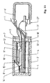
- Fig. 11 shows the donor according to Fig. 10 with lid open 6 '.
- the conveyor bracket 7 ' performs when opening the lid 6' a delivery stroke for driving and promotion of a platelet-shaped substance 1 from the stack 4 to the removal opening 5 'from.
- the plate-like substance 1 protrudes out of the removal opening 5 ', so that it can be grasped with fingers.
- the platelet-shaped substance 1 lies on a platelet guide 31 ', which has a straight and a curved portion.
- the curved section leads the platelet-shaped substance 1 from the removal opening 5 'upwards out, so that it can be easily grasped with fingers.
- the conveyor bracket 7 ' performs when opening the lid 6' a delivery stroke for taking and promotion of the platelet-shaped substance 1 from the stack 4 to the removal opening 5 'from.
- the conveyor bow 7 ' which is under elastic pretensioning, moves at least partially under a guide track 10' during the delivery stroke and makes contact with its contact surface 32 'with the uppermost platelet-shaped material 1 of the stack 4.
- the conveyor bracket 7' When closing the lid 6 ', the conveyor bracket 7' is guided on the guideway 10 'within the housing 2' in such a way that it passes without contact through the stack 4 of the platelet-shaped substances 1.
- the guideway 10 ' is formed as a ramp, which is formed on a locked in the housing 2' component 14 '.
- the component 14 ' is also referred to as a tray.
- the component 14 ' is separate from Housing 2 'and the lid 6' made and is locked to the housing 2 'for mounting.
- the conveyor bracket 7 ' jumps when closing the lid 6' due to its curvature and elastic bias of a traversing end 15 'of the guide track 10' on a spacer 8 ', wherein the lid 6', the housing 2 'closes.
- the conveyor bracket 7 ' is positively guided by a bending guide 16'.
- Fig. 11 It can be seen that the cover 6 'performs a translatory, namely axial, movement relative to the housing 2'.
- the cover 6 ' is guided in the housing 2' in the manner of a drawer and has a seal 27 'facing the removal opening 5', which is designed as an olive seal.
- Fig. 12 shows an exploded view of the dispenser according to Fig. 10
- Fig. 12 shows that the donor according to Fig. 10 has a three-part construction. Each of its three individual parts is injection-molded from plastic.
- the lid 6 'and the conveyor bracket 7' are integrally formed.
- the conveyor bracket 7 ' is formed as an elastically deformable body from which on both sides side arms 20', 21 'protrude.
- the component 14 ' can be latched to the housing 2'.
- the guide track 10' is formed.
- the spacer 8' is formed, which is designed as a spacer bevel.
- the guideway 10 ' is associated with the detent 11'.
- a stop 18' is formed, in which the side arms 20 ', 21' can engage.
- the component 14 'furthermore has the platelet guide 31', which guides the platelet-shaped substances 1 to the removal opening 5 '.
- the component 14 ' is introduced into the housing 2' of the container by a latching.
- the component 14 ' is fixed relative to the housing 2' relatively immovable.
- the component 14 ' can be filled with the stack 4.
- the cover 6 ' is mounted.
- the conveyor bracket 7 ' must be placed on the guideway 10'.
- the housing 2 'and the removal opening 5' is closed.
- the olive seal 27 'on the cover 6' ensures that the housing 2 'is liquid-tight and gas-tight.
- Fig. 13 shows a perspective view of the component 14 '.
- Fig. 14 shows a perspective view of the lid 6 '.
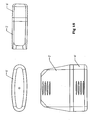
- Fig. 15 shows three views on a closed dispenser according to Fig. 10
- Top left in Fig. 15 is a view of the lid 6 'shown in its direction of displacement.
- the view in the upper right in Fig. 15 shows a side view of the dispenser according to Fig. 10
- Bottom left in Fig. 15 is a plan view of the dispenser according to Fig. 10 shown.
Landscapes
- Engineering & Computer Science (AREA)
- Mechanical Engineering (AREA)
- Closures For Containers (AREA)
- Medical Preparation Storing Or Oral Administration Devices (AREA)
Description
- Die Erfindung betrifft einen Spender zur Darreichung von plättchenförmigen Stoffen, umfassend ein Gehäuse, wobei das Gehäuse einen Hohlraum zur Lagerung eines Stapels der plättchenförmigen Stoffe aufweist, wobei das Gehäuse eine Entnahmeöffnung für die plättchenförmigen Stoffe ausbildet, die durch einen Deckel öffenbar und wieder verschließbar ist, wobei der Deckel mit dem Gehäuse verbunden ist und wobei der Deckel mit einem Förderbügel verbunden ist, welcher zusammen mit dem Deckel zur Förderung der plättchenförmigen Stoffe bewegbar ist.
- Aus dem Stand der Technik sind bereits derartige Spender zur Aufnahme und Darreichung von plättchenförmigen Stoffen bekannt. Bei den plättchenförmigen Stoffen handelt es sich meist um verzehrbare, wasserlösliche Plättchen zur oralen oder anderen Versorgung. Bekannt sind plättchenförmige Stoffe, die als Arzneimittel, Nahrungsergänzungsmittel, Süßigkeiten, Kosmetikartikel oder Hygieneartikel ausgebildet sind. Die plättchenförmigen Stoffe sind häufig in regelmäßige Rechtecke vorgeschnitten und werden in einem Stapel innerhalb des Gehäuses gelagert.
- Die plättchenförmigen Stoffe werden üblicherweise durch eine Entnahmeöffnung aus dem Gehäuse entnommen. Hierbei ist jedoch nachteilig, dass die Entnahmeöffnungen häufig relativ klein und die plättchenförmigen Stoffe daher nur mit Mühe entnehmbar sind.
- Die
US 2005/0 092 763 A1 offenbart vor diesem Hintergrund einen Spender, der durch Verschieben eines Deckels geöffnet werden kann. Die plättchenförmigen Stoffe werden durch eine Erhebung in Richtung der Entnahmeöffnung gedrückt, damit diese entnommen werden können. - Bei den plättchenförmigen Stoffen handelt es sich oft um filmartige, wasserlösliche Plättchen, die relativ empfindlich gegen Feuchtigkeit sind. Dabei ist insbesondere problematisch ist, dass die plättchenförmigen Stoffe nach einiger Zeit Feuchtigkeit aufnehmen und sich dabei zersetzen und aneinander kleben.
- Einen gegen Feuchtigkeit abgedichteten Spender beschreibt die
WO 2005/051 822 A1 . Dieser weist einen Förderbügel auf, welcher bei geschlossenem Gehäuse auf dem Stapel der plättchenförmigen Stoffe aufliegt. Hierdurch können allerdings die empfindlichen plättchenförmigen Stoffe aneinander gepresst werden und miteinander verkleben. - Es ist weiter problematisch, dass eine Person, welche in die Entnahmeöffnung hineinfasst, die im Gehäuse verbleibenden plättchenförmigen Stoffe kontaminieren kann. Insbesondere bei der Verwendung von Arzneimitteln in den genannten Spendern können Krankheitskeime auf weitere Benutzer des Spenders übertragen werden.
- Die
US 2005/0 274 733 A1 begegnet diesem Problem mit einem Spender, der die plättchenförmigen Stoffe durch einen Schiebevorgang aus dem Gehäuse herausführt. Der Spender weist hierzu einen Förderbügel auf, welcher bei geschlossenem Gehäuse auf dem Stapel der plättchenförmigen Stoffe aufliegt. Hierdurch können allerdings die plättchenförmigen Stoffe aneinander gepresst werden und miteinander verkleben. - Durch die
DE 201 19 188 U1 und dieWO 2004/024 593 A1 sind jeweils ein Spender bekannt geworden, bei dem die plättchenförmigen Stoffe unter Ausübung händischen Drucks gefördert werden. Ein Förderbügel muss durch händischen Druck zur Förderung der plättchenförmigen Stoffe auf diese gepresst werden. Hierbei muss der Druck sehr genau dosiert werden, damit nicht ungewollt zwei oder mehrere plättchenförmige Stoffe gefördert werden. Dieses Problem stellt sich insbesondere, wenn die plättchenförmigen Stoffe aneinander anhaften. - Ein weiterer Spender ist aus der
FR 2 879 573 - Es besteht daher ein Bedarf nach einem Spender, der eine zuverlässige und sichere Darreichung eines einzelnen plättchenförmigen Stoffes beim Öffnen des Gehäuses erlaubt. Dabei soll die Darreichung in eine Hand oder direkt oral erfolgen, ohne dass die Finger der bedienenden Person in das Gehäuse oder an den plättchenförmigen Stoff gelangen. Der Bedarf an solchen Spendern besteht insbesondere in der Medizin bei der Darreichung von Arzneimitteln.
- Der Erfindung liegt daher die Aufgabe zugrunde, einen Spender der eingangs genannten Art derart auszugestalten und weiterzubilden, dass dieser eine kontaminationsfreie und zuverlässige Förderung eines einzelnen plättchenförmigen Stoffes aus dem Inneren des Gehäuses allein durch Bewegung des Deckels ermöglicht.
- Erfindungsgemäß wird die voranstehende Aufgabe durch einen Spender mit den Merkmalen des Patentanspruchs 1 gelöst.
- Danach ist ein Spender der eingangs genannten Art dadurch gekennzeichnet, dass der Förderbügel elastisch vorgespannt ist und derart im Gehäuse gelagert ist, dass er bei geschlossener Entnahmeöffnung vom Stapel beabstandet ist.
- In erfindungsgemäßer Weise ist zunächst erkannt worden, dass die Verwendung eines Förderbügels erlaubt, einen plättchenförmigen Stoff aus dem Inneren des Gehäuses aus der Entnahmeöffnung herauszufördern, ohne dass mit Fingern in das Innere des Gehäuses gefasst werden muss. Weiter ist erkannt worden, dass ein unter elastischer Vorspannung stehender Förderbügel derart kraftbeaufschlagt werden kann, dass dieser von einem Stapel definiert einzelne Plättchen bzw. einen einzelnen plättchenförmigen Stoff abzieht und zur Entnahmeöffnung fördert. Des Weiteren ist erkannt worden, dass die Finger nur den Deckel anfassen müssen, um den Förderbügel und damit einen plättchenförmigen Stoff zu bewegen. Das Innere des Gehäuses wird daher nicht kontaminiert. Schließlich ist erkannt worden, dass ein vom Stapel beabstandeter Förderbügel die plättchenförmigen Stoffe nicht aneinanderpresst und dadurch ein Verkleben der Stoffe verhindert. Insoweit ist ein Spender angegeben, welcher eine kontaminationsfreie und zuverlässige Förderung einzelner plättchenförmiger Stoffe zu einer Entnahmeöffnung des Spenders realisiert.
- Der Förderbügel könnte bei geschlossener Entnahmeöffnung zur Beabstandung vom Stapel auf einem Abstandshalter ruhen. Hierdurch ist sichergestellt, dass der Förderbügel bei geschlossenem Gehäuse die plättchenförmigen Stoffe nicht mit Druck beaufschlagt. Es wird sichergestellt, dass die plättchenförmigen Stoffe nicht aneinandergepresst werden und miteinander verkleben können.
- Der Förderbügel könnte beim Öffnen der Entnahmeöffnung einen Förderhub zur Mitnahme und Förderung eines plättchenförmigen Stoffes vom Stapel zur Entnahmeöffnung ausführen. Durch diese konkrete Ausgestaltung kann der plättchenförmige Stoff allein durch Betätigung des Deckels aus dem Inneren des Gehäuses derart zur Entnahmeöffnung verbracht werden, dass der plättchenförmige Stoff teilweise aus der Entnahmeöffnung herausragt. Die den Spender bedienende Person kann daher den plättchenförmigen Stoff mit ihren Fingern ergreifen, ohne die im Hohlraum des Gehäuses verbleibenden plättchenförmigen Stoffe zu kontaminieren.
- Vor diesem Hintergrund könnte der Förderbügel während des Förderhubs zumindest teilweise unter einer Führungsbahn verfahren. Indem der Förderbügel unter einer rampenartigen Führungsbahn verfährt, kann er mit einer abgerundeten, wulstartigen Kontaktfläche den obersten plättchenförmigen Stoff des Stapels kontaktieren und diesen zur Entnahmeöffnung mitnehmen.
- Der Förderbügel könnte bei einer definierten Öffnungsstellung des Deckels eine Raste unterfahren, um an einem Anfahrende der Führungsbahn zur Anlage kommen. Bei dieser konkreten Ausgestaltung unterfährt der Förderbügel eine elastisch deformierbare Raste derart, dass diese vom Ende des Förderbügels nach einer elastischen Deformierung in ihre Ruhelage herabspringt. Hierdurch kann der Förderbügel nicht mehr auf den bereits zurückgelegten Weg zurückkehren. Die Raste versperrt dem Förderbügel den zurückgelegten Weg. Die elastisch deformierbare Raste funktioniert bei dieser konkreten Ausgestaltung in Analogie zu einem Rückschlagventil. Nach dem Unterfahren der Raste kommt der Förderbügel an einem Anfahrende einer rampenartigen Führungsbahn zur Anlage.
- Der Förderbügel könnte beim Schließen der Entnahmeöffnung derart auf einer Führungsbahn innerhalb des Gehäuses geleitet sein, dass er den Stapel der plättchenförmigen Stoffe kontaktlos passiert. Beim Schließen des Deckels wird der Förderbügel auf der rampenartigen Führungsbahn geführt und legt einen Weg zurück, der oberhalb des Weges liegt, welchen der Förderbügel beim Öffnen des Deckels ausführt. Durch die Führung auf der rampenartigen Führungsbahn wird der Förderbügel von dem Stapel der plättchenförmigen Stoffe beabstandet und hat mit diesem keinen Kontakt. Hierdurch wird vermieden, dass der Förderbügel die im Gehäuse verbleibenden plättchenförmigen Stoffe zusammenschiebt, staucht, faltet oder zerknüllt.
- Die Führung könnte als Rampe ausgebildet sein, die aus einem im Gehäuse eingerasteten Bauteil ausgebildet ist. Das Bauteil kann separat zum Gehäuse gefertigt werden und in dieses verliersicher eingerastet werden. Hierdurch ist es möglich, Führungsbahnen unterschiedlicher Steigungen und Längen unabhängig vom Gehäuse zu gestalten. Insbesondere ist es möglich, das Bauteil aus einem Material zu fertigen, welches sich vom Material des Gehäuses unterscheidet. Vor diesem Hintergrund ist konkret denkbar, dass das Bauteil ein Trockenmittel einschließt oder aus einem Trockenmittelcompound gefertigt ist. Das Trockenmittel absorbiert Flüssigkeit, welche in das Gehäuse eingedrungen ist. Das Bauteil wird auch als Tray bezeichnet.
- Der Förderbügel konnte beim Schließen der Entnahmeöffnung aufgrund seiner elastischen Vorspannung von einem Verfahrende der Führungsbahn auf einen Abstandshalter springen, wobei der Deckel das Gehäuse verschließt. Der Deckel kann dadurch kraftbeaufschlagt an das Gehäuse dichtend herangezogen werden. Der elastisch deformierbare Förderbügel entfaltet eine Rückstellkraft, die genutzt wird, um den Deckel dichtend an das Gehäuse heranzuziehen.
- Vor diesem Hintergrund könnte der Förderbügel als elastisch deformierbarer Körper ausgebildet sein, von welchem beidseitig Seitenarme abragen. Die Ausgestaltung als elastisch deformierbarer Körper erlaubt es, den Förderbügel beim Öffnungsvorgang und beim Schließvorgang flexibel reversibel zu verbiegen. Hierfür können im Gehäuse Biegehilfen ausgestaltet sein, welche den Förderbügel beim Öffnen und Schließen des Deckels krümmen. Abragende Seitenarme erlauben es, den Förderbügel unter Krümmung auf einer Führungsbahn zu führen. Dabei können die Seitenarme auf der Führungsbahn geführt werden, wobei ein Hauptast die Zugkraft oder die Schubkraft des bewegten Deckels auf die Seitenarme übertragt.
- Der Deckel und der Förderbügel könnten einstückig ausgebildet sein, wobei der Deckel über Klemmnocken mit dem Gehäuse verbunden ist. Die Klemmnocken erlauben, den Deckel separat zu fertigen und mit dem Gehäuse verliersicher zu verbinden. Der mit dem Förderbügel einstückig ausgebildete Deckel könnte aus einem weicheren Material bestehen als das Gehäuse. Hierdurch kann der Deckel beim Anpressen an das Gehäuse eine sehr gute Dichtwirkung entfalten. Das Eindringen von Feuchtigkeit in das Innere des Gehäuses wird verhindert. Es ist auch denkbar, dass der Deckel aus zwei Komponenten, insbesondere durch 2-K-Spritzgießen, gefertigt ist.
- Die Klemmnocken könnten mit einem starren Teil einstückig ausgebildet sein, an welchem der Deckel über ein Filmscharnier schwenkbar angelenkt ist. Bei dieser konkreten Ausgestaltung kann der Förderbügel durch Schwenken des Deckels bewegt werden. Der elastisch deformierbare Förderbügel folgt geführt durch Biegehilfen der gekrümmten Bahn des Deckels beim Öffnen und Schließen, nämlich beim Verschwenken um das Filmscharnier.
- Vor diesem Hintergrund ist auch denkbar, dass der Deckel beim Öffnen und Schließen der Entnahmeöffnung eine translatorische Bewegung ausführt. Hierbei kann der Deckel im Sinne einer Schublade vom Gehäuse weggezogen oder in dieses hineingeschoben werden. Ein Spender mit dieser konkreten Ausgestaltung baut äußerst flach und zeichnet sich durch eine hohe Kompaktheit aus.
- Der Deckel könnte an der Seite, welche der Entnahmeöffnung zugewandt ist, eine umlaufende Dichtung aufweisen. Durch die Dichtung ist sichergestellt, dass die Entnahmeöffnung bei geschlossenem Deckel feuchtigkeitsdicht oder luftdicht verschließbar ist. Ein Spender dieser Ausgestaltung kann feuchtigkeitsempfindliche Arzneimittel, Kosmetika, oral verabreichbare Duftstoffe oder Hygieneartikel aufnehmen. Der Spender kann Wirkstoffplättchen aufnehmen, welche sich im Mund durch Feuchtigkeit kurzfristig auflösen, im Spender aber dauerhaft lagerbar sind. Hierzu kann im Inneren des Spenders ein Trockenmittel aufgenommen sein.
- Die Dichtung könnte als Olivendichtung ausgebildet sein. Eine Olivendichtung weist einen konvex ausgebildeten Wulst auf, welcher in eine konkav ausgebildete Nut einrastet oder einschnappt. Durch eine Olivendichtung kann der Deckel nur mit Kraftaufwand vom Gehäuse gelöst werden. Die Olivendichtung ist gerade nicht flächig ausgebildet, sondern verläuft im Inneren des Gehäuses.
- Der Spender könnte dreiteilig aufgebaut sein, nämlich aus drei Einzelteilen bestehen, welche jeweils separat spritzgegossen sind. Durch diese konkrete Ausgestaltung ist der Spender einfach zu fertigen und weist eine nur geringe Anzahl von Einzelteilen auf, die miteinander verrastet oder verpresst werden müssen.
- Der hier beschriebene Spender kann z.B. zahnaufhellende Mittel, Nahrungsergänzungsmittel, Vitamine, Geschmacksstoffe, Geruchsstoffe, Parfüme, Schlafmittel, Verhütungsmittel, Hormone, Appetitzügler, Arzneimittel, oral verabreichbare Duftstoffe und Elektrolyte für Sportler aufnehmen.
- Des Weiteren kann der Spender verwendet werden, um Hautpflegemittel in den Tropen, insbesondere Sonnencreme, aufzunehmen. Der Spender kann auch Seife, Kosmetikartikel, Papier, insbesondere Visitenkarten, oder Haushaltsartikel aufnehmen.
- Letztlich kann der hier beschriebene Spender nahezu alle dünnen Plättchen aufnehmen und fördern, welche gestapelt im Gehäuse des Spenders aufnehmbar sind. Die Plättchen haben dabei vorzugsweise eine Breite von 23 mm und eine Länge von 28 mm.
- Der hier beschriebene Spender zeichnet sich durch eine sehr hohe Kompaktheit aus und passt beispielsweise in Hosentaschen oder Handtaschen. Er ist des Weiteren leicht handhabbar, da allein durch Öffnen des Deckels ein plättchenförmiger Stoff gefördert wird.
- Den Menschen, die keine Pillen schlucken können, können plättchenförmige Stoffe oral verabreicht werden. Der Spender ermöglicht eine sehr gute orale Darreichungsform für Kinder und ältere Menschen. Die plättchenförmigen Stoffe erlauben einen schnellen Wirkstofftransport durch die Schleimhaut. Dabei ist denkbar, den Spender mit einer Kindersicherung auszustatten.
- Der hier beschriebene Spender erlaubt eine kosteneffiziente Darreichungsform und kann bis zu 65 mg an Wirkstoffen transportieren.
- Weitere Ziele, Merkmale, Vorteile und Anwendungsmöglichkeiten der vorliegenden Erfindung ergeben sich aus der nachfolgenden Beschreibung von Ausführungsbeispielen anhand der Zeichnung. Dabei bilden alle beschriebenen und / oder bildlich dargestellten Merkmale für sich oder in beliebiger Kombination den Gegenstand der Erfindung, unabhängig von der Zusammenfassung in einzelnen Ansprüchen oder deren Rückbeziehung.
- In der Zeichnung zeigen
- Fig. 1
- eine Schnittansicht eines geschlossenen Spenders mit gewölbtem Gehäuse,
- Fig. 2
- eine Schnittansicht des Gehäuses gemäß
Fig. 1 , wobei der Deckel geöffnet ist, - Fig. 3
- eine Schnittansicht des Gehäuses gemäß
Fig. 1 , wobei der Deckel eine Schließbewegung durchläuft, - Fig. 4
- eine perspektivische Ansicht des Gehäuses des Spenders gemäß
Fig. 1 , welches aus einem Oberteil und einem Unterteil besteht, - Fig. 5
- eine perspektivische Ansicht des Förderbügels und des einstückig mit diesem verbundenen Deckels,
- Fig. 6
- eine perspektivische Ansicht des Bauteils, welches eine Führungsbahn aufweist und mit dem Unterteil des Gehäuses gemäß
Fig. 4 verrastbar ist, - Fig. 7
- eine perspektivische Ansicht der drei Einzelteile der
Figuren 4 bis 5 in einer Explosionsdarstellung des Spenders gemäßFig. 1 , - Fig. 8
- eine perspektivische Ansicht des Spenders gemäß
Fig. 1 mit geöffnetem Deckel, - Fig. 9
- drei Ansichten des geschlossenen Spenders gemäß
Fig. 1 , - Fig. 10
- eine Schnittansicht eines geschlossenen Spenders, dessen Deckel durch eine translatorische, nämlich axiale, Bewegung bewegbar ist,
- Fig. 11
- eine Schnittansicht des Spenders gemäß
Fig. 10 mit geöffnetem Deckel, - Fig. 12
- eine perspektivische Ansicht der drei Einzelteile, aus welchen der Spender gemäß
Fig. 10 besteht, - Fig. 13
- eine perspektivische Ansicht des Bauteils, welches mit dem Gehäuse des Spenders gemäß
Fig. 10 unbeweglich verrastet ist, - Fig. 14
- eine perspektivische Ansicht des Deckels des Spenders gemäß
Fig. 10 und - Fig. 15
- drei Ansichten des Spenders gemäß
Fig. 10 . - In den
Fig. 1 bis 15 kennzeichnen gleiche Bezugszeichen jeweils gleiche Elemente des jeweils dargestellten Spenders. -
Fig. 1 zeigt einen Spender zur Darreichung von plättchenförmigen Stoffen 1, umfassend ein Gehäuse 2, wobei das Gehäuse 2 einen Hohlraum 3 zur Lagerung eines Stapels 4 der plättchenförmigen Stoffe 1 aufweist, wobei das Gehäuse 2 eine Entnahmeöffnung 5 für die plättchenförmigen Stoffe 1 ausbildet, die durch einen Deckel 6 öffenbar und wieder verschließbar ist, und wobei der Deckel 6 mit dem Gehäuse 2 verbunden ist. Der Deckel 6 ist mit einem Förderbügel 7 verbunden, welcher zusammen mit dem Deckel 6 zur Förderung der plättchenförmigen Stoffe 1 bewegbar ist. Der Förderbügel 7 ist elastisch vorgespannt und derart im Gehäuse 2 gelagert, dass er bei geschlossenem Gehäuse 2 bzw. geschlossener Entnahmeöffnung 5 vom Stapel 4 beabstandet ist. - Der Förderbügel 7 ruht bei geschlossenem Deckel 6 zur Beabstandung vom Stapel 4 auf einem Abstandshalter 8. Der Abstandshalter 8 ist als Abstandsschräge ausgebildet. Am Deckel 6 ist ein Griff 9 zum Ergreifen des Deckels 6 ausgebildet.
-
Fig. 2 zeigt eine Schnittansicht des Spenders gemäßFig. 1 mit geöffnetem Deckel 6. Der Förderbügel 7 führt beim Öffnen des Deckels 6 einen Förderhub zur Mitnahme und Förderung des plättchenförmigen Stoffes 1 vom Stapel 4 zur Entnahmeöffnung 5 aus. Der beim Öffnen des Deckels 6 zu der Entnahmeöffnung durch den Förderbügel 7 vorgeschobene plättchenförmige Stoff 1 ragt aus der Entnahmeöffnung 5 heraus und kann mit Fingern ergriffen werden. Der Förderbügel 7 ist derart am Deckel 6 angelenkt, dass er einen Eingriff in die Entnahmeöffnung 5 mit Fingern im Wesentlichen verhindert. - Während des Förderhubs verfährt der Förderbügel 7 unter Krümmung zumindest teilweise unter einer Führungsbahn 10, also auf deren dem Stapel 4 zugewandten Seite. Bei einer definierten Öffnungsstellung des Deckels 6 unterfährt der Förderbügel 7 eine Raste 11 und kommt dadurch an einem Anfahrende 12 der Führungsbahn 10 zur Anlage.
-
Fig. 3 zeigt eine Schnittansicht des Spenders gemäßFig. 1 , bei welchem der Deckel 6 eine Schließbewegung ausführt. Der Förderbügel 7 wird beim Schließen des Deckels 6 derart auf der Führungsbahn 10 innerhalb des Gehäuses 2 geleitet, dass er den Stapel 4 der plättchenförmigen Stoffe 1 kontaktlos passiert und mit einem Abstand über diesen hinwegbewegt wird. Der Förderbügel 7 wird durch eine erste Biegehilfe 13 und die Führungsbahn 10 unter elastischer Vorspannung stehend gekrümmt. - Die Führungsbahn 10 ist als Rampe ausgebildet und auf einem im Gehäuse 2 eingerasteten Bauteil 14 ausgebildet. Das Bauteil 14 wird auch als Tray bezeichnet.
- Der Förderbügel 7 springt beim Schließen des Deckels 6 aufgrund der Krümmung und seiner elastischen Vorspannung von einem Verfahrende 15 der Führungsbahn 10 auf den Abstandshalter 8, wobei der Deckel 6 das Gehäuse 2 verschließt. Der Förderbügel 7 wird dabei von einer zweiten Biegehilfe 16 nach unten auf den Abstandshalter 8 geführt.
- Der Deckel 6 führt beim Öffnen und Schließen der Entnahmeöffnung 5 eine Schwenkbewegung aus. Beim Öffnen des Deckels 6 wird der elastisch deformierbare Förderbügel 7 von der ersten Biegehilfe 13 und einer dritten Biegehilfe 17 gekrümmt, die dritte Biegehilfe 17 führt dabei den Förderbügel 7 zu einem Anschlag 18. Beim Schließen des Deckels 6 wird der elastisch deformierbare Förderbügel 7 durch die erste Biegehilfe 13 und die rampenartige Führungsbahn 10 gekrümmt. Die zweite Biegehilfe 16 zwingt den unter elastischer Vorspannung stehenden Förderbügel 7 auf den Abstandshalter 8 beim Schließen des Deckels 6. Der Anschlag 18 verhindert, dass der elastische Förderbügel 7 beim Öffnen des Deckels 6 über eine definierte Auszugsposition hinaus aus dem Gehäuse 2 herausgezogen wird.
-
Fig. 4 zeigt in einer perspektivischen Ansicht das Gehäuse 2 des Spenders gemäß denFig. 1 bis 3 . Das Gehäuse 2 ist aus Kunststoff spritzgegossen und besteht aus einem Oberteil 2a und einem Unterteil 2b. Das Oberteil 2a und das Unterteil 2b sind durch einen Verbindungssteg 19, der als Filmscharnier ausgebildet ist, schwenkbar aneinander angelenkt. Im Oberteil 2a ist die Entnahmeöffnung 5 ausgebildet, die vom Förderbügel 7 durchgriffen werden kann. Das Oberteil 2a weist des Weiteren die erste Biegehilfe 13 auf, welche als im Wesentlichen L-förmig, U-förmig oder hakenförmig gekrümmte Zunge ausgebildet ist. Dabei ragt das Ende der Zunge in Richtung der Entnahmeöffnung 5. Schließlich sind im Oberteil 2a beidseitig zwei Bauteilhalter 2c, 2d zum Halten des Bauteils 14 ausgebildet. - Im Unterteil 2b ist die dritte Biegehilfe 17 ausgebildet. An diese schließt sich der Anschlag 18 an. Die dritte Biegehilfe 17 und der Anschlag 18 sind auf zwei Seiten des Unterteils 2b angeordnet. Im Unterteil 2b ist des Weiteren der als Abstandsschräge ausgebildete Abstandshalter 8 ausgebildet. Der Abstandshalter 8 ist als zweistufige Abstandsschräge mit zwei unterschiedlich gekrümmten Schrägstufen ausgebildet.
- Im Unterteil 2b ist des Weiteren eine Plättchenführung 31 ausgeformt. Die Plättchenführung 31 ist rampenartig ausgestaltet und führt die plättchenförmigen Stoffe 1 zur Entnahmeöffnung 5. Im Unterteil 2b sind des Weiteren aus zwei Seiten stegartige Vorsprünge 2e ausgebildet, auf welche das Bauteil 14 aufsetzbar ist. Das Gehäuse 2 ist derart gestaltet, dass es ohne einen Schieber aus einer Spritzgussform entformt werden kann.
-
Fig. 5 zeigt eine perspektivische Ansicht des Deckels 6, welcher einstückig mit dem Förderbügel 7 ausgebildet ist. Der Förderbügel 7 ist als elastisch deformierbarer Körper ausgebildet, von welchem beidseitig Seitenarme 20, 21 abragen. Die Seitenarme 20, 21 ragen vom Ende 22 des Förderbügels 7 ab. Der Deckel 6 ist über Klemmnocken 23 mit dem Gehäuse 2 verpresst. Ganz konkret greifen vier Klemmnocken 23 in vier Aufnahmen 24 für die Klemmnocken 23 im Oberteil 2a ein. Der Deckel 6 ist daher mit dem Oberteil 2a des Gehäuses 2 verliersicher verbunden. Die Klemmnocken 23 sind mit einem starren Teil 25 einstückig ausgebildet, an welchem der Deckel 6 über ein Filmscharnier 26 schwenkbar angelenkt ist. - Der Deckel 6 weist eine an dessen der Entnahmeöffnung 5 zugewandten Seite umlaufende Dichtung 27 auf. Die Dichtung 27 ist als Olivendichtung ausgebildet. Der Förderbügel 7 weist einen Hauptast 28 auf, welcher durch die erste Biegehilfe 13 und die dritte Biegehilfe 17 elastisch deformiert und gekrümmt wird. Die zweite Biegehilfe 16 zwingt das Ende 22 des Förderbügel 7, von welchem die Seitenarme 20, 21 abragen, auf den Abstandshalter 8. Die Seitenarme 20, 21 werden auf der rampenartigen Führungsbahn 10 geführt.
- Der Förderbügel 7 weist an seinem Ende 22 eine wulstartige, gekrümmte Kontaktfläche 32 auf, welche mit den plättchenförmigen Stoffen 1 bei deren Mitnahme in Kontakt tritt.
- Es ist auch denkbar, den Deckel 6 durch 2-K-Spritzgießen oder auch zweiteilig aus unterschiedlichen Komponenten herzustellen.
-
Fig. 6 zeigt das Bauteil 14, welches mit dem Unterteil 2b des Gehäuses 2 durch Montagerasten 29 verrastet wird, die als Vertiefungen ausgestaltet sind. Das Bauteil 14 weist des Weiteren gabelartige Zentrierhilfen 30 auf, welche stegartige Vorsprünge 2e im Unterteil 2b des Gehäuses 2 umgreifen. Die Montagerasten 29 und die Zentrierhilfen 30 sind an zwei Seiten des Bauteils 14 ausgebildet. Das Bauteil 14 weist des Weiteren die rampenartige Führungsbahn 10 auf, auf welcher die Seitenarme 20, 21 des Förderbügels 7 geführt werden. Ein Teil der Führungsbahn 10 ist die Raste 11, welche als elastisch deformierbare Zunge ausgebildet ist. Die Raste 11 weist ein Anfahrende 12 der Führungsbahn 10 auf, über welches die Seitenarme 20, 21 des Förderbügels 7 auf die Führungsbahn 10 geführt werden. Durch diese Führung der Seitenarme 20, 21 wird der Förderbügel 7 kontaktlos am Stapel 4 vorbeigeführt. Am Bauteil 14 ist des Weiteren die zweite Biegehilfe 16 ausgebildet, welche das Ende 22 des Förderbügels 7, von welchem die Seitenarme 20, 21 abragen, auf den Abstandshalter 8 zwingt. -
Fig. 7 zeigt eine perspektivische Explosionsdarstellung der drei Einzelteile, aus welchem der Spender gemäßFig. 1 gefertigt ist. Zur Herstellung des Spenders wird das aus Kunststoff spritzgegossene Bauteil 14, das Tray, in das Unterteil 2b des Gehäuses 2 durch eine Verrastung eingebracht. Darauf wird das Unterteil 2b mit den plättchenförmigen Stoffen 1 gefüllt. Im Anschluss daran wird der Deckel 6 mit den Klemmnocken 23 in das Oberteil 2a eingepresst. - Der Förderbügel 7 muss unter Vorspannung montiert werden, damit er genügend Druck auf die plättchenförmigen Stoffe 1 zu deren Mitnahme und Förderung ausüben kann. Bei der Montage des Deckels 6 wird der Förderbügel 7 auf die Führungsbahn 10 aufgesetzt.
- Darauf wird das Oberteil 2a mit dem Unterteil 2b verbunden. Bei diesem Montageschritt ist darauf zu achten, dass der Förderbügel 7 nicht von der Führungsbahn 10 abrutscht. Bei Durchführung dieses Montageschritts springt der Förderbügel 7 auf den Abstandshalter 8. Die dauerhafte Verbindung des Oberteils 2a mit dem Unterteil 2b kann, wenn gewünscht, durch Ultraschallschweißen oder Reibschweißen glatter aneinanderliegender Fügeflächen oder durch Kleben erfolgen.
- Der Spender ist fertig montiert und für die Darreichung der plättchenförmigen Stoffe 1 bereitgestellt. Nach jeder Förderung eines plättchenförmigen Stoffes 1 springt der Förderbügel 7 beim Schließen des Deckels 6 auf den Abstandshalter 8 zurück, um von dort erneut loszufahren, wenn der Deckel 6 geöffnet wird. Die elastische Vorspannung des Förderbügels 7, mit welcher er den Stapel 4 kontaktiert, ist derart zu wählen, dass er auch den letzten auf dem Stapel 4 verbliebenen plättchenförmigen Stoff 1 noch zuverlässig zur Entnahmeöffnung 5 fördert.
-
Fig. 8 zeigt eine perspektivische Ansicht des Spenders mit geöffnetem Deckel 6. Aus der Entnahmeöffnung 5 ragt ein plättchenförmiger Stoff 1 in Form eines Plättchens heraus. Der Förderbügel 7 durchgreift die Entnahmeöffnung 5 derart, dass mit Fingern nur äußerst schwierig in das Innere des Gehäuses 2 eingegriffen werden kann. Eine Kontamination der plättchenförmigen Stoffe 1 im Inneren des Gehäuses 2 wird hierdurch wirksam vermieden. Die Olivendichtung 27 am Deckel 6 dichtet das Gehäuse 2 flüssigkeitsdicht und gasdicht gegen die Atmosphäre ab. -
Fig. 9 zeigt drei Ansichten des geschlossenen Spenders gemäßFig. 1 . Die Ansicht links oben inFig. 9 zeigt eine Ansicht auf den Deckel 6 in Richtung der Längsachse des Gehäuses 2. Die Ansicht oben rechts inFig. 9 zeigt eine Seitenansicht des Spenders. Die Ansicht unten rechts inFig. 9 zeigt eine Draufsicht auf den Deckel 6 des Spenders. -
Fig. 10 zeigt eine weitere Ausführungsform eines Spenders zur Darreichung von plättchenförmigen Stoffen 1, umfassend ein Gehäuse 2', wobei das Gehäuse 2' einen Hohlraum 3' zur Lagerung eines Stapels 4 der plättchenförmigen Stoffe 1 aufweist, wobei das Gehäuse 2' eine Entnahmeöffnung 5' für die plättchenförmigen Stoffe 1 ausbildet, die durch einen Deckel 6' öffenbar und wieder verschließbar ist, und wobei der Deckel 6' mit dem Gehäuse 2' verbunden ist. Der Deckel 6' ist mit einem Förderbügel 7' verbunden, welcher zusammen mit dem Deckel 6' zur Förderung der plättchenförmigen Stoffe 1 bewegbar ist. Der Förderbügel 7' ist elastisch vorgespannt und derart im Gehäuse 2' gelagert, dass er bei geschlossenem Gehäuse 2' bzw. geschlossener Entnahmeöffnung 5' vom Stapel 4 beabstandet ist. - Der Förderbügel 7' ruht bei geschlossenem Deckel 6' zur Beabstandung vom Stapel 4 auf einem Abstandshalter 8'. Seine wulstartige, abgerundete Kontaktfläche 32' berührt den Stapel 4 nicht.
-
Fig. 11 zeigt den Spender gemäßFig. 10 mit geöffnetem Deckel 6'. Der Förderbügel 7' führt beim Öffnen des Deckels 6' einen Förderhub zur Mitnahme und Förderung eines plättchenförmigen Stoffes 1 vom Stapel 4 zur Entnahmeöffnung 5' aus. Der plättchenförmige Stoff 1 ragt aus der Entnahmeöffnung 5' heraus, so dass er mit Fingern gegriffen werden kann. Der plättchenförmige Stoff 1 liegt dabei auf einer Plättchenführung 31' auf, welche einen geraden und einen gekrümmten Abschnitt aufweist. Der gekrümmte Abschnitt führt den plättchenförmigen Stoff 1 aus der Entnahmeöffnung 5' nach oben heraus, so dass dieser problemlos mit Fingern ergriffen werden kann. - Der Förderbügel 7' führt beim Öffnen des Deckels 6' einen Förderhub zur Mitnahme und Förderung des plättchenförmigen Stoffes 1 vom Stapel 4 zur Entnahmeöffnung 5' aus. Dabei verfährt der unter einer elastischen Vorspannung stehende Förderbügel 7' während des Förderhubs zumindest teilweise unter einer Führungsbahn 10' und kontaktiert mit seiner Kontaktfläche 32' den obersten plättchenförmigen Stoff 1 des Stapels 4.
- Bei einer definierten Öffnungsstellung des Deckels 6' unterfährt der Förderbügel 7' eine elastische, zungenförmige Raste 11' und kann dadurch an einem Anfahrende 12' der Führungsbahn 10' zur Anlage kommen. Beim Unterfahren der Führungsbahn 10' liegt der Förderbügel 7' mit seiner Kontaktfläche 32' auf dem Stapel 4 unter einer elastischen Vorspannung auf. Die elastische Vorspannung des Förderbügels 7' ist stets so zu wählen, dass auch der letzte plättchenförmige Stoff 1 von Stapel 4 entnommen wird. Hierdurch ist eine Restentleerung des Spenders sichergestellt. Die Ausführungen in Bezug auf die Kontaktfläche 32' sowie die Vorspannung des Förderbügels 7' zur Herstellung einer Restentleerung gelten auch für den Spender gemäß
Fig. 1 . - Beim Schließen des Deckels 6' ist der Förderbügel 7' derart auf der Führungsbahn 10' innerhalb des Gehäuses 2' geleitet, dass er den Stapel 4 der plättchenförmigen Stoffe 1 kontaktlos passiert.
- Die Führungsbahn 10' ist als Rampe ausgebildet, die auf einem im Gehäuse 2' eingerasteten Bauteil 14' ausgebildet ist. Das Bauteil 14' wird auch als Tray bezeichnet. Das Bauteil 14' ist separat vom Gehäuse 2' und dem Deckel 6' hergestellt und wird mit dem Gehäuse 2' zur Montage verrastet.
- Der Förderbügel 7' springt beim Schließen des Deckels 6' aufgrund seiner Krümmung und elastischen Vorspannung von einem Verfahrende 15' der Führungsbahn 10' auf einen Abstandshalter 8', wobei der Deckel 6' das Gehäuse 2' verschließt. Der Förderbügel 7' wird dabei von einer Biegeführung 16' zwangsgeführt.
- Der Deckel 6' führt beim Öffnen und Schließen der Entnahmeöffnung 5' eine translatorische Bewegung aus. In
Fig. 11 ist erkennbar, dass der Deckel 6' eine translatorische, nämlich axiale Bewegung, relativ zum Gehäuse 2' ausführt. Der Deckel 6' ist in dem Gehäuse 2' nach Art einer Schublade geführt und weist eine an dessen Entnahmeöffnung 5' zugewandte Dichtung 27' auf, welche als Olivendichtung ausgebildet ist. -
Fig. 12 zeigt eine Explosionsdarstellung des Spenders gemäßFig. 10 .Fig. 12 zeigt, dass der Spender gemäßFig. 10 einen dreiteiligen Aufbau aufweist. Jedes seiner drei Einzelteile ist aus Kunststoff spritzgegossen. - Der Deckel 6' und der Förderbügel 7' sind einstückig ausgebildet. Der Förderbügel 7' ist als elastisch deformierbarer Körper ausgebildet, von welchem beidseitig Seitenarme 20', 21' abragen.
- Das Bauteil 14' ist mit dem Gehäuse 2' verrastbar. Im Bauteil 14' ist die Führungsbahn 10' ausgebildet. Des Weiteren ist im Bauteil 14' der Abstandshalter 8' ausgebildet, welcher als Abstandsschräge ausgeführt ist. Der Führungsbahn 10' ist die Raste 11' zugeordnet. Im Bauteil 14' ist des Weiteren ein Anschlag 18' ausgebildet, in welchen die Seitenarme 20', 21' eingreifen können. Der Anschlag 18' weist beidseitig angeordnete hakenartige Laschen auf, in welche die Seitenarme 20', 21' eingreifen können. Hierdurch kann verhindert werden, dass der Deckel 6' über eine definierte Öffnungsstellung gezogen wird.
- Erst wenn der Förderbügel 7' am Anschlag 18' angekommen und die Raste 11' unterfahren hat, kann der Förderbügel 7' auf der Führungsbahn 10' kontaktlos über den Stapel 4 hinweggeführt werden. Danach springt der Förderbügel 7' vom Verfahrende 15' unter Einwirkung einer Biegeführung 16' auf den Abstandshalter 8' und ruht dort bis zum erneuten Öffnen des Deckels 6'. Die hakenartige Biegeführung 16' zwingt den Förderbügel 7' auf den Abstandshalter 8'. Die Biegeführung 16' ist beidseitig im Bauteil 14' ausgebildet. Die Biegeführung 16' ist in Form nach oben ragender, gekrümmter Haken ausgestaltet.
- Das Bauteil 14' weist des Weiteren die Plättchenführung 31' auf, welche die plättchenförmigen Stoffe 1 zur Entnahmeöffnung 5' führt.
- Zur Montage des Spenders gemäß
Fig. 10 wird das Bauteil 14' in das Gehäuse 2' des Behälters durch eine Verrastung eingebracht. Das Bauteil 14' wird dabei zum Gehäuse 2' relativ unbeweglich festgelegt. Wenn dies erfolgt ist, kann das Bauteil 14' mit dem Stapel 4 befüllt werden. Darauf wird der Deckel 6' montiert. Hierbei muss der Förderbügel 7' auf die Führungsbahn 10' aufgesetzt werden. Der Förderbügel 7' springt, wie zuvor beschrieben, vom Verfahrende 15' der Führungsbahn 10', wenn der Deckel 6' mit dem Bauteil 14' verrastet wird. Indem der Deckel 6' mit dem Bauteil 14' verrastet wird, wird das Gehäuse 2' bzw. die Entnahmeöffnung 5' verschlossen. Die Olivendichtung 27' am Deckel 6' stellt sicher, dass das Gehäuse 2' flüssigkeitsdicht und gasdicht verschlossen ist. - Am Bauteil 14' sind beidseitig im Querschnitt L-förmige Führungsschienen 33 ausgebildet, in welche Führungsstege 34 am Deckel 6' einfahren können. Der Deckel 6' wird mit dem Bauteil 14' durch die beidseitig angeordneten Rastnasen 35 verrastet und ist relativ zum Gehäuse 2' und relativ zum Bauteil 14' verschieblich bewegbar.
-
Fig. 13 zeigt eine perspektivische Ansicht des Bauteils 14'.Fig. 14 zeigt eine perspektivische Ansicht des Deckels 6'. -
Fig. 15 zeigt drei Ansichten auf einen geschlossenen Spender gemäßFig. 10 . Oben links inFig. 15 ist eine Ansicht auf den Deckel 6' in dessen Verschieberichtung gezeigt. Die Ansicht oben rechts inFig. 15 zeigt eine Seitenansicht des Spenders gemäßFig. 10 . Unten links inFig. 15 ist eine Draufsicht auf den Spender gemäßFig. 10 gezeigt. - Hinsichtlich weiterer vorteilhafter Ausgestaltungen und Weiterbildungen der erfindungsgemäßen Lehre wird einerseits auf den allgemeinen Teil der Beschreibung und andererseits auf die Patentansprüche verwiesen.
Claims (15)
- Spender zur Darreichung von plättchenförmigen Stoffen (1), umfassend ein Gehäuse (2, 2'), wobei das Gehäuse (2, 2') einen Hohlraum (3, 3') zur Lagerung eines Stapels (4) der plättchenförmigen Stoffe (1) aufweist, wobei das Gehäuse (2, 2') eine Entnahmeöffnung (5, 5') für die plättchenförmigen Stoffe (1) ausbildet, die durch einen Deckel (6, 6') öffenbar und wieder verschließbar ist, wobei der Deckel (6, 6') mit dem Gehäuse (2, 2') verbunden ist und wobei der Deckel (6, 6') mit einem Förderbügel (7, 7') verbunden ist, welcher zusammen mit dem Deckel (6, 6') zur Förderung der plättchenförmigen Stoffe (1) bewegbar ist, dadurch gekennzeichnet, dass der Förderbügel (7, 7') elastisch vorgespannt ist und derart im Gehäuse (2, 2') gelagert ist, dass er bei geschlossener Entnahmeöffnung (5, 5') vom Stapel (4) beabstandet ist.
- Spender nach Anspruch 1, dadurch gekennzeichnet, dass der Förderbügel (7, 7') bei geschlossener Entnahmeöffnung (5, 5') zur Beabstandung vom Stapel (4, 4') auf einem Abstandshalter (8, 8') ruht.
- Spender nach Anspruch 1 oder 2, dadurch gekennzeichnet, dass der Förderbügel (7, 7') beim Öffnen der Entnahmeöffnung (5, 5') einen Förderhub zur Mitnahme und Förderung eines plättchenförmigen Stoffes (1) vom Stapel (4) zur Entnahmeöffnung (5, 5') ausführt.
- Spender nach Anspruch 3, dadurch gekennzeichnet, dass der Förderbügel (7, 7') während des Förderhubs zumindest teilweise unter einer Führungsbahn (10, 10') verfährt.
- Spender nach einem der Ansprüche 1 bis 4, dadurch gekennzeichnet, dass der Förderbügel (7, 7') bei einer definierten Öffnungsstellung des Deckels (6, 6') eine Raste (11, 11') unterfährt, um an einem Anfahrende (12, 12') der Führungsbahn (10, 10') zur Anlage zu kommen.
- Spender nach einem der Ansprüche 1 bis 5, dadurch gekennzeichnet, dass der Förderbügel (7, 7') beim Schließen der Entnahmeöffnung (5, 5') derart auf einer Führungsbahn (10, 10') innerhalb des Gehäuses (2, 2') geleitet ist, dass er den Stapel (4) der plättchenförmigen Stoffe (1) kontaktlos passiert.
- Spender nach Anspruch 6, dadurch gekennzeichnet, dass die Führungsbahn (10, 10') als Rampe ausgebildet ist, die auf einem im Gehäuse (2, 2') eingerasteten Bauteil (14, 14') ausgebildet ist.
- Spender nach Anspruch 6 oder 7, dadurch gekennzeichnet, dass der Förderbügel (7, 7') beim Schließen der Entnahmeöffnung (5, 5') aufgrund seiner elastischen Vorspannung von einem Verfahrende (15, 15') der Führungsbahn (10, 10') auf einen Abstandshalter (8, 8') springt und der Deckel (6, 6') das Gehäuse (2, 2') verschließt.
- Spender nach einem der Ansprüche 1 bis 8, dadurch
gekennzeichnet dass der Förderbügel (7, 7') als elastisch deformierbarer Körper ausgebildet ist, von welchem beidseitig Seitenarme (20, 20', 21, 21') abragen. - Spender nach einem der Ansprüche 1 bis 9, dadurch gekennzeichnet, dass der Deckel (6) und der Förderbügel (7) einstückig ausgebildet sind, wobei der Deckel (6) über Klemmnocken (23) mit dem Gehäuse (2) verbunden ist.
- Spender nach Anspruch 10, dadurch gekennzeichnet, dass die Klemmnocken (23) mit einem starren Teil (25) einstückig ausgebildet sind, an welchem der Deckel (6) über ein Filmscharnier (26) schwenkbar angelenkt ist.
- Spender nach einem der Ansprüche 1 bis 9, dadurch gekennzeichnet, dass der Deckel (6') beim Öffnen und Schließen der Entnahmeöffnung (5') eine translatorische Bewegung ausführt.
- Spender nach einem der Ansprüche 1 bis 12, dadurch gekennzeichnet, dass der Deckel (6, 6') eine an dessen der Entnahmeöffnung (5, 5') zugewandten Seite umlaufende Dichtung (27, 27') aufweist.
- Spender nach Anspruch 13, dadurch gekennzeichnet, dass die Dichtung (27, 27') als Olivendichtung ausgebildet ist.
- Spender nach einem der Ansprüche 1 bis 14, gekennzeichnet durch einen dreiteiligen Aufbau, wobei jedes der drei Einzelteile spritzgegossen ist.
Applications Claiming Priority (2)
| Application Number | Priority Date | Filing Date | Title |
|---|---|---|---|
| DE102009014134A DE102009014134A1 (de) | 2009-03-24 | 2009-03-24 | Spender zur Darreichung von plättchenförmigen Stoffen |
| PCT/EP2010/001799 WO2010108649A1 (de) | 2009-03-24 | 2010-03-23 | Spender zur darreichung von plättchenförmigen stoffen |
Publications (2)
| Publication Number | Publication Date |
|---|---|
| EP2411303A1 EP2411303A1 (de) | 2012-02-01 |
| EP2411303B1 true EP2411303B1 (de) | 2013-03-06 |
Family
ID=42236741
Family Applications (1)
| Application Number | Title | Priority Date | Filing Date |
|---|---|---|---|
| EP10716756A Not-in-force EP2411303B1 (de) | 2009-03-24 | 2010-03-23 | Spender zur darreichung von plättchenförmigen stoffen |
Country Status (6)
| Country | Link |
|---|---|
| US (1) | US8672181B2 (de) |
| EP (1) | EP2411303B1 (de) |
| JP (1) | JP2012521334A (de) |
| CA (1) | CA2754344A1 (de) |
| DE (1) | DE102009014134A1 (de) |
| WO (1) | WO2010108649A1 (de) |
Families Citing this family (3)
| Publication number | Priority date | Publication date | Assignee | Title |
|---|---|---|---|---|
| JP2007513840A (ja) * | 2003-11-24 | 2007-05-31 | シーエスピー テクノロジーズ,インコーポレイティド | 防湿の可食性フィルムディスペンサとその方法 |
| US9125795B2 (en) * | 2010-07-06 | 2015-09-08 | Tania Degian | Blood sugar management system |
| USD915211S1 (en) | 2019-08-06 | 2021-04-06 | Kimberly-Clark Worldwide, Inc. | Cleaning product dispenser |
Family Cites Families (17)
| Publication number | Priority date | Publication date | Assignee | Title |
|---|---|---|---|---|
| US3276622A (en) * | 1964-04-01 | 1966-10-04 | Milprint Inc | Dispenser carton |
| US4071165A (en) * | 1975-12-29 | 1978-01-31 | Norbert Leopoldi | Paper dispenser having a frictional discharge assistant |
| US4739902A (en) * | 1986-02-05 | 1988-04-26 | Rockline, Inc. | Container for storing and dispensing paper articles |
| US5197630A (en) * | 1991-11-25 | 1993-03-30 | Kirla Stanley J | Dispenser for nested conical articles |
| DE10084095D2 (de) | 1999-12-23 | 2002-07-11 | Alfred Von Schuckmann | Spender zur Ausgabe von Streifenelementen |
| DE20119188U1 (de) | 2001-11-27 | 2002-02-21 | Storz, Achim, Zell am See | Vorrichtung zur Ausgabe von filmartig dünnen Oblaten aus Nahrungs- oder Erfrischungsmitteln |
| AU2003270428A1 (en) | 2002-09-12 | 2004-04-30 | Colgate-Palmolive Company | Dispenser for thin sheets |
| US7661555B1 (en) * | 2002-12-13 | 2010-02-16 | Union Street Brand Packaging | Single dispensing film strip container |
| US20050092763A1 (en) | 2003-11-03 | 2005-05-05 | Kraft Foods Holdings, Inc. | Package for storing and dispensing edible film strips |
| FR2862622B1 (fr) | 2003-11-24 | 2006-01-27 | Oreal | Dispositif de conditionnement et de distribution de produits empiles, notamment de produits cosmetiques sur support |
| JP2007513840A (ja) | 2003-11-24 | 2007-05-31 | シーエスピー テクノロジーズ,インコーポレイティド | 防湿の可食性フィルムディスペンサとその方法 |
| TWI440453B (zh) * | 2004-02-18 | 2014-06-11 | Universal Biosensors Pty Ltd | 試片排出系統 |
| US7320413B2 (en) | 2004-06-08 | 2008-01-22 | Fusi John C | Self-closing dispensing container |
| US20090302048A1 (en) | 2004-12-21 | 2009-12-10 | Airsec | Device for storing and dispensing in single units objects in the form of sheets or thin strips |
| US20080142535A1 (en) * | 2006-12-19 | 2008-06-19 | Ari Tao Adler | Personal care product dispenser |
| US7946450B2 (en) * | 2008-04-25 | 2011-05-24 | R.J. Reynolds Tobacco Company | Dispensing container |
| US8397945B2 (en) * | 2010-02-23 | 2013-03-19 | R.J. Reynolds Tobacco Company | Dispensing container |
-
2009
- 2009-03-24 DE DE102009014134A patent/DE102009014134A1/de not_active Withdrawn
-
2010
- 2010-03-23 WO PCT/EP2010/001799 patent/WO2010108649A1/de not_active Ceased
- 2010-03-23 CA CA2754344A patent/CA2754344A1/en not_active Abandoned
- 2010-03-23 JP JP2012501178A patent/JP2012521334A/ja not_active Withdrawn
- 2010-03-23 EP EP10716756A patent/EP2411303B1/de not_active Not-in-force
- 2010-03-23 US US13/202,232 patent/US8672181B2/en not_active Expired - Fee Related
Also Published As
| Publication number | Publication date |
|---|---|
| WO2010108649A1 (de) | 2010-09-30 |
| US20110297695A1 (en) | 2011-12-08 |
| JP2012521334A (ja) | 2012-09-13 |
| CA2754344A1 (en) | 2010-09-30 |
| US8672181B2 (en) | 2014-03-18 |
| DE102009014134A1 (de) | 2010-09-30 |
| EP2411303A1 (de) | 2012-02-01 |
Similar Documents
| Publication | Publication Date | Title |
|---|---|---|
| DE60124913T2 (de) | Spender für medien | |
| DE69434207T2 (de) | Gerät zum aufbringen mehrerer medikamente ins auge, ohne vorherige mischung im gerät | |
| AT396872B (de) | Gerät zur verabreichung von medikamenten in pulverform | |
| EP1132104B1 (de) | Spender für Medien | |
| WO2009071415A1 (de) | Tablettendispenser | |
| DE4436051C2 (de) | Vorrichtung zum Betätigen von Aerosolabgabegeräten | |
| DE29514137U1 (de) | Tablettenspender | |
| US20090184022A1 (en) | Child resistant container for housing a blister card | |
| DE20119188U1 (de) | Vorrichtung zur Ausgabe von filmartig dünnen Oblaten aus Nahrungs- oder Erfrischungsmitteln | |
| DE3419619A1 (de) | Schminkdose | |
| DE3230947A1 (de) | Spender fuer pastoeses gut, insbesondere zahnpasta | |
| DE10307590A1 (de) | Kindersichere Blisterpackung | |
| DE3523173A1 (de) | Spender | |
| WO2014111249A2 (de) | Kindergesicherter behälterverschluss | |
| EP2411303A1 (de) | Spender zur darreichung von plättchenförmigen stoffen | |
| EP3131518B1 (de) | Mehrkammerbeutelöffnungshilfe | |
| EP1499538A2 (de) | Einwegventil zur abgabe eines fliessfähigen materials | |
| DE69907039T2 (de) | Biegsamer antriebsmechanismus sowie abgabevorrichtung enthaltend einen solchen mechanismus | |
| DE60107268T2 (de) | Einzeldosis oder zweidosen spendevorrichtung für fliessfähiges gut | |
| DE4216541C2 (de) | Mehrfach verwendbarer Dosierspender | |
| DE60303963T2 (de) | ABGABEVORRICHTUNG FÜR FLUID ODER PULVERFöRMIGES PRODUKT | |
| EP2830975B1 (de) | Spender | |
| WO2009156109A1 (de) | Ausdrückvorrichtung | |
| DE102009026267B4 (de) | Tablettenzerteiler und Aufbewahrungsmittel für Tabletten | |
| EP3492394B1 (de) | Vorrichtung zum dosierten befüllen eines trinkhalms mit einem füllgut |
Legal Events
| Date | Code | Title | Description |
|---|---|---|---|
| PUAI | Public reference made under article 153(3) epc to a published international application that has entered the european phase |
Free format text: ORIGINAL CODE: 0009012 |
|
| 17P | Request for examination filed |
Effective date: 20111005 |
|
| AK | Designated contracting states |
Kind code of ref document: A1 Designated state(s): AT BE BG CH CY CZ DE DK EE ES FI FR GB GR HR HU IE IS IT LI LT LU LV MC MK MT NL NO PL PT RO SE SI SK SM TR |
|
| DAX | Request for extension of the european patent (deleted) | ||
| GRAP | Despatch of communication of intention to grant a patent |
Free format text: ORIGINAL CODE: EPIDOSNIGR1 |
|
| GRAS | Grant fee paid |
Free format text: ORIGINAL CODE: EPIDOSNIGR3 |
|
| GRAA | (expected) grant |
Free format text: ORIGINAL CODE: 0009210 |
|
| AK | Designated contracting states |
Kind code of ref document: B1 Designated state(s): AT BE BG CH CY CZ DE DK EE ES FI FR GB GR HR HU IE IS IT LI LT LU LV MC MK MT NL NO PL PT RO SE SI SK SM TR |
|
| REG | Reference to a national code |
Ref country code: GB Ref legal event code: FG4D Free format text: NOT ENGLISH |
|
| REG | Reference to a national code |
Ref country code: CH Ref legal event code: EP Ref country code: AT Ref legal event code: REF Ref document number: 599474 Country of ref document: AT Kind code of ref document: T Effective date: 20130315 |
|
| REG | Reference to a national code |
Ref country code: IE Ref legal event code: FG4D Free format text: LANGUAGE OF EP DOCUMENT: GERMAN |
|
| REG | Reference to a national code |
Ref country code: CH Ref legal event code: NV Representative=s name: HEPP WENGER RYFFEL AG, CH |
|
| REG | Reference to a national code |
Ref country code: DE Ref legal event code: R096 Ref document number: 502010002463 Country of ref document: DE Effective date: 20130502 |
|
| PG25 | Lapsed in a contracting state [announced via postgrant information from national office to epo] |
Ref country code: BG Free format text: LAPSE BECAUSE OF FAILURE TO SUBMIT A TRANSLATION OF THE DESCRIPTION OR TO PAY THE FEE WITHIN THE PRESCRIBED TIME-LIMIT Effective date: 20130606 Ref country code: LT Free format text: LAPSE BECAUSE OF FAILURE TO SUBMIT A TRANSLATION OF THE DESCRIPTION OR TO PAY THE FEE WITHIN THE PRESCRIBED TIME-LIMIT Effective date: 20130306 Ref country code: SE Free format text: LAPSE BECAUSE OF FAILURE TO SUBMIT A TRANSLATION OF THE DESCRIPTION OR TO PAY THE FEE WITHIN THE PRESCRIBED TIME-LIMIT Effective date: 20130306 Ref country code: ES Free format text: LAPSE BECAUSE OF FAILURE TO SUBMIT A TRANSLATION OF THE DESCRIPTION OR TO PAY THE FEE WITHIN THE PRESCRIBED TIME-LIMIT Effective date: 20130617 Ref country code: NO Free format text: LAPSE BECAUSE OF FAILURE TO SUBMIT A TRANSLATION OF THE DESCRIPTION OR TO PAY THE FEE WITHIN THE PRESCRIBED TIME-LIMIT Effective date: 20130606 |
|
| REG | Reference to a national code |
Ref country code: NL Ref legal event code: VDEP Effective date: 20130306 |
|
| REG | Reference to a national code |
Ref country code: LT Ref legal event code: MG4D |
|
| PG25 | Lapsed in a contracting state [announced via postgrant information from national office to epo] |
Ref country code: GR Free format text: LAPSE BECAUSE OF FAILURE TO SUBMIT A TRANSLATION OF THE DESCRIPTION OR TO PAY THE FEE WITHIN THE PRESCRIBED TIME-LIMIT Effective date: 20130607 Ref country code: FI Free format text: LAPSE BECAUSE OF FAILURE TO SUBMIT A TRANSLATION OF THE DESCRIPTION OR TO PAY THE FEE WITHIN THE PRESCRIBED TIME-LIMIT Effective date: 20130306 Ref country code: SI Free format text: LAPSE BECAUSE OF FAILURE TO SUBMIT A TRANSLATION OF THE DESCRIPTION OR TO PAY THE FEE WITHIN THE PRESCRIBED TIME-LIMIT Effective date: 20130306 Ref country code: LV Free format text: LAPSE BECAUSE OF FAILURE TO SUBMIT A TRANSLATION OF THE DESCRIPTION OR TO PAY THE FEE WITHIN THE PRESCRIBED TIME-LIMIT Effective date: 20130306 |
|
| BERE | Be: lapsed |
Owner name: SANNER G.M.B.H. Effective date: 20130331 |
|
| PG25 | Lapsed in a contracting state [announced via postgrant information from national office to epo] |
Ref country code: HR Free format text: LAPSE BECAUSE OF FAILURE TO SUBMIT A TRANSLATION OF THE DESCRIPTION OR TO PAY THE FEE WITHIN THE PRESCRIBED TIME-LIMIT Effective date: 20130306 |
|
| PG25 | Lapsed in a contracting state [announced via postgrant information from national office to epo] |
Ref country code: NL Free format text: LAPSE BECAUSE OF FAILURE TO SUBMIT A TRANSLATION OF THE DESCRIPTION OR TO PAY THE FEE WITHIN THE PRESCRIBED TIME-LIMIT Effective date: 20130306 Ref country code: IS Free format text: LAPSE BECAUSE OF FAILURE TO SUBMIT A TRANSLATION OF THE DESCRIPTION OR TO PAY THE FEE WITHIN THE PRESCRIBED TIME-LIMIT Effective date: 20130706 Ref country code: EE Free format text: LAPSE BECAUSE OF FAILURE TO SUBMIT A TRANSLATION OF THE DESCRIPTION OR TO PAY THE FEE WITHIN THE PRESCRIBED TIME-LIMIT Effective date: 20130306 Ref country code: CZ Free format text: LAPSE BECAUSE OF FAILURE TO SUBMIT A TRANSLATION OF THE DESCRIPTION OR TO PAY THE FEE WITHIN THE PRESCRIBED TIME-LIMIT Effective date: 20130306 Ref country code: MC Free format text: LAPSE BECAUSE OF NON-PAYMENT OF DUE FEES Effective date: 20130331 Ref country code: PT Free format text: LAPSE BECAUSE OF FAILURE TO SUBMIT A TRANSLATION OF THE DESCRIPTION OR TO PAY THE FEE WITHIN THE PRESCRIBED TIME-LIMIT Effective date: 20130708 Ref country code: RO Free format text: LAPSE BECAUSE OF FAILURE TO SUBMIT A TRANSLATION OF THE DESCRIPTION OR TO PAY THE FEE WITHIN THE PRESCRIBED TIME-LIMIT Effective date: 20130306 Ref country code: SK Free format text: LAPSE BECAUSE OF FAILURE TO SUBMIT A TRANSLATION OF THE DESCRIPTION OR TO PAY THE FEE WITHIN THE PRESCRIBED TIME-LIMIT Effective date: 20130306 |
|
| PG25 | Lapsed in a contracting state [announced via postgrant information from national office to epo] |
Ref country code: PL Free format text: LAPSE BECAUSE OF FAILURE TO SUBMIT A TRANSLATION OF THE DESCRIPTION OR TO PAY THE FEE WITHIN THE PRESCRIBED TIME-LIMIT Effective date: 20130306 |
|
| REG | Reference to a national code |
Ref country code: IE Ref legal event code: MM4A |
|
| PLBE | No opposition filed within time limit |
Free format text: ORIGINAL CODE: 0009261 |
|
| STAA | Information on the status of an ep patent application or granted ep patent |
Free format text: STATUS: NO OPPOSITION FILED WITHIN TIME LIMIT |
|
| PG25 | Lapsed in a contracting state [announced via postgrant information from national office to epo] |
Ref country code: BE Free format text: LAPSE BECAUSE OF NON-PAYMENT OF DUE FEES Effective date: 20130331 Ref country code: IE Free format text: LAPSE BECAUSE OF NON-PAYMENT OF DUE FEES Effective date: 20130323 Ref country code: DK Free format text: LAPSE BECAUSE OF FAILURE TO SUBMIT A TRANSLATION OF THE DESCRIPTION OR TO PAY THE FEE WITHIN THE PRESCRIBED TIME-LIMIT Effective date: 20130306 |
|
| 26N | No opposition filed |
Effective date: 20131209 |
|
| PG25 | Lapsed in a contracting state [announced via postgrant information from national office to epo] |
Ref country code: IT Free format text: LAPSE BECAUSE OF FAILURE TO SUBMIT A TRANSLATION OF THE DESCRIPTION OR TO PAY THE FEE WITHIN THE PRESCRIBED TIME-LIMIT Effective date: 20130306 |
|
| REG | Reference to a national code |
Ref country code: DE Ref legal event code: R097 Ref document number: 502010002463 Country of ref document: DE Effective date: 20131209 |
|
| PG25 | Lapsed in a contracting state [announced via postgrant information from national office to epo] |
Ref country code: MT Free format text: LAPSE BECAUSE OF FAILURE TO SUBMIT A TRANSLATION OF THE DESCRIPTION OR TO PAY THE FEE WITHIN THE PRESCRIBED TIME-LIMIT Effective date: 20130306 |
|
| PG25 | Lapsed in a contracting state [announced via postgrant information from national office to epo] |
Ref country code: SM Free format text: LAPSE BECAUSE OF FAILURE TO SUBMIT A TRANSLATION OF THE DESCRIPTION OR TO PAY THE FEE WITHIN THE PRESCRIBED TIME-LIMIT Effective date: 20130306 |
|
| PG25 | Lapsed in a contracting state [announced via postgrant information from national office to epo] |
Ref country code: CY Free format text: LAPSE BECAUSE OF FAILURE TO SUBMIT A TRANSLATION OF THE DESCRIPTION OR TO PAY THE FEE WITHIN THE PRESCRIBED TIME-LIMIT Effective date: 20130306 Ref country code: TR Free format text: LAPSE BECAUSE OF FAILURE TO SUBMIT A TRANSLATION OF THE DESCRIPTION OR TO PAY THE FEE WITHIN THE PRESCRIBED TIME-LIMIT Effective date: 20130306 |
|
| PG25 | Lapsed in a contracting state [announced via postgrant information from national office to epo] |
Ref country code: LU Free format text: LAPSE BECAUSE OF NON-PAYMENT OF DUE FEES Effective date: 20130323 Ref country code: MK Free format text: LAPSE BECAUSE OF FAILURE TO SUBMIT A TRANSLATION OF THE DESCRIPTION OR TO PAY THE FEE WITHIN THE PRESCRIBED TIME-LIMIT Effective date: 20130306 Ref country code: HU Free format text: LAPSE BECAUSE OF FAILURE TO SUBMIT A TRANSLATION OF THE DESCRIPTION OR TO PAY THE FEE WITHIN THE PRESCRIBED TIME-LIMIT; INVALID AB INITIO Effective date: 20100323 |
|
| REG | Reference to a national code |
Ref country code: FR Ref legal event code: PLFP Year of fee payment: 7 |
|
| REG | Reference to a national code |
Ref country code: AT Ref legal event code: MM01 Ref document number: 599474 Country of ref document: AT Kind code of ref document: T Effective date: 20150323 |
|
| PG25 | Lapsed in a contracting state [announced via postgrant information from national office to epo] |
Ref country code: AT Free format text: LAPSE BECAUSE OF NON-PAYMENT OF DUE FEES Effective date: 20150323 |
|
| REG | Reference to a national code |
Ref country code: FR Ref legal event code: PLFP Year of fee payment: 8 |
|
| PGFP | Annual fee paid to national office [announced via postgrant information from national office to epo] |
Ref country code: CH Payment date: 20170327 Year of fee payment: 8 Ref country code: FR Payment date: 20170323 Year of fee payment: 8 Ref country code: DE Payment date: 20170327 Year of fee payment: 8 |
|
| PGFP | Annual fee paid to national office [announced via postgrant information from national office to epo] |
Ref country code: GB Payment date: 20170327 Year of fee payment: 8 |
|
| REG | Reference to a national code |
Ref country code: DE Ref legal event code: R119 Ref document number: 502010002463 Country of ref document: DE |
|
| REG | Reference to a national code |
Ref country code: CH Ref legal event code: PL |
|
| GBPC | Gb: european patent ceased through non-payment of renewal fee |
Effective date: 20180323 |
|
| PG25 | Lapsed in a contracting state [announced via postgrant information from national office to epo] |
Ref country code: DE Free format text: LAPSE BECAUSE OF NON-PAYMENT OF DUE FEES Effective date: 20181002 |
|
| PG25 | Lapsed in a contracting state [announced via postgrant information from national office to epo] |
Ref country code: CH Free format text: LAPSE BECAUSE OF NON-PAYMENT OF DUE FEES Effective date: 20180331 Ref country code: GB Free format text: LAPSE BECAUSE OF NON-PAYMENT OF DUE FEES Effective date: 20180323 Ref country code: LI Free format text: LAPSE BECAUSE OF NON-PAYMENT OF DUE FEES Effective date: 20180331 |
|
| PG25 | Lapsed in a contracting state [announced via postgrant information from national office to epo] |
Ref country code: FR Free format text: LAPSE BECAUSE OF NON-PAYMENT OF DUE FEES Effective date: 20180331 |