EP2830975B1 - Spender - Google Patents
Spender Download PDFInfo
- Publication number
- EP2830975B1 EP2830975B1 EP13717163.3A EP13717163A EP2830975B1 EP 2830975 B1 EP2830975 B1 EP 2830975B1 EP 13717163 A EP13717163 A EP 13717163A EP 2830975 B1 EP2830975 B1 EP 2830975B1
- Authority
- EP
- European Patent Office
- Prior art keywords
- dispenser
- housing
- blocking element
- button
- tamper
- Prior art date
- Legal status (The legal status is an assumption and is not a legal conclusion. Google has not performed a legal analysis and makes no representation as to the accuracy of the status listed.)
- Active
Links
- 230000000903 blocking effect Effects 0.000 claims description 39
- 230000033001 locomotion Effects 0.000 claims description 8
- 210000003811 finger Anatomy 0.000 description 5
- 210000003813 thumb Anatomy 0.000 description 4
- 238000005452 bending Methods 0.000 description 3
- 235000003599 food sweetener Nutrition 0.000 description 3
- 239000003765 sweetening agent Substances 0.000 description 3
- 230000004888 barrier function Effects 0.000 description 2
- 230000001419 dependent effect Effects 0.000 description 2
- 208000014674 injury Diseases 0.000 description 2
- 238000000926 separation method Methods 0.000 description 2
- 208000027418 Wounds and injury Diseases 0.000 description 1
- 210000003484 anatomy Anatomy 0.000 description 1
- 230000006378 damage Effects 0.000 description 1
- 238000011161 development Methods 0.000 description 1
- 230000018109 developmental process Effects 0.000 description 1
- 238000006073 displacement reaction Methods 0.000 description 1
- 230000000694 effects Effects 0.000 description 1
- 230000002996 emotional effect Effects 0.000 description 1
- 238000003780 insertion Methods 0.000 description 1
- 230000037431 insertion Effects 0.000 description 1
- 230000010354 integration Effects 0.000 description 1
- 230000007257 malfunction Effects 0.000 description 1
- 238000004519 manufacturing process Methods 0.000 description 1
- 230000000007 visual effect Effects 0.000 description 1
Images


Classifications
-
- B—PERFORMING OPERATIONS; TRANSPORTING
- B65—CONVEYING; PACKING; STORING; HANDLING THIN OR FILAMENTARY MATERIAL
- B65D—CONTAINERS FOR STORAGE OR TRANSPORT OF ARTICLES OR MATERIALS, e.g. BAGS, BARRELS, BOTTLES, BOXES, CANS, CARTONS, CRATES, DRUMS, JARS, TANKS, HOPPERS, FORWARDING CONTAINERS; ACCESSORIES, CLOSURES, OR FITTINGS THEREFOR; PACKAGING ELEMENTS; PACKAGES
- B65D83/00—Containers or packages with special means for dispensing contents
- B65D83/04—Containers or packages with special means for dispensing contents for dispensing annular, disc-shaped, or spherical or like small articles, e.g. tablets or pills
- B65D83/0409—Containers or packages with special means for dispensing contents for dispensing annular, disc-shaped, or spherical or like small articles, e.g. tablets or pills the dispensing means being adapted for delivering one article, or a single dose, upon each actuation
-
- B—PERFORMING OPERATIONS; TRANSPORTING
- B65—CONVEYING; PACKING; STORING; HANDLING THIN OR FILAMENTARY MATERIAL
- B65D—CONTAINERS FOR STORAGE OR TRANSPORT OF ARTICLES OR MATERIALS, e.g. BAGS, BARRELS, BOTTLES, BOXES, CANS, CARTONS, CRATES, DRUMS, JARS, TANKS, HOPPERS, FORWARDING CONTAINERS; ACCESSORIES, CLOSURES, OR FITTINGS THEREFOR; PACKAGING ELEMENTS; PACKAGES
- B65D2401/00—Tamper-indicating means
- B65D2401/55—Tamper-indicating means based on a change or a contrast in colour
-
- B—PERFORMING OPERATIONS; TRANSPORTING
- B65—CONVEYING; PACKING; STORING; HANDLING THIN OR FILAMENTARY MATERIAL
- B65D—CONTAINERS FOR STORAGE OR TRANSPORT OF ARTICLES OR MATERIALS, e.g. BAGS, BARRELS, BOTTLES, BOXES, CANS, CARTONS, CRATES, DRUMS, JARS, TANKS, HOPPERS, FORWARDING CONTAINERS; ACCESSORIES, CLOSURES, OR FITTINGS THEREFOR; PACKAGING ELEMENTS; PACKAGES
- B65D2583/00—Containers or packages with special means for dispensing contents
- B65D2583/04—For dispensing annular, disc-shaped or spherical or like small articles or tablets
- B65D2583/0472—For dispensing annular, disc-shaped or spherical or like small articles or tablets characterised by the dispensing action
- B65D2583/0477—For dispensing annular, disc-shaped or spherical or like small articles or tablets characterised by the dispensing action the container is maintained in the same position during the dispensing of several successive articles or doses
- B65D2583/0481—One reciprocating action, e.g. to or from
Definitions
- the present invention relates to an article according to the preamble of claim 1.
- a dispenser for tablets or the like is a dispenser for tablets or the like.
- lumpy Well known which has a dispenser housing with a lower footprint and in its housing a storage space for storing the Guts.
- the dispensed Good is transferred by means of an output mechanism to a present at least in the actuation case discharge opening, wherein the dispenser for actuating the dispensing mechanism associated with this, a movable key and to block the operation prior to the first issue of Guts a tamper-evident.
- Such a donor is usually operated by persons with the thumb.
- the DE 91 06 050 U1 discloses a tamper dispenser with tamper evidence in which the position and direction of recesses formed on the container part and lid are determined such that a tamper-evident band covers the lid and the dispenser pusher as well as the tablet failure opening.
- This originality band is arranged circumferentially over the entire height of the dispenser and covers the arranged on the bottom discharge port.
- the WO 2004/000703 A1 discloses a tablet dispenser with a separating mechanism, the lower end of which can be closed by means of a tabbed, cross-shaped tamper-evident element. By pulling on the tab, the originality element can be removed from the tablet dispenser and removed.
- the key of the dispenser to be actuated is designed as a side key which is movable after violation of the originality with at least one movement component in a direction transverse to a vertical standing on the lower contact surface.
- the tamper-indicating closure has a blocking element which blocks an actuation of the side key or an output of the item before violation of the originality.
- the operation of the donor is aligned with the fingers, which already encircle the donor anyway. There are fewer fingers to spend to spend the goods, which is advantageous especially for people with reduced mobility.
- the output of the product can be done by the same movement as the gripping of the donor.
- the tamper-evident closure is adapted to previously block an actuation of this side key or an output of the item, so that inadvertent operation of the dispenser during or before sale can be precluded.
- an operable portion of the tamper-evident closure may also be disposed in a side area near or immediately adjacent to a side key, particularly with respect to a vertical on a lower footprint in the lower half of the dispenser.
- the blocking element counteracts a relative movement of the side key and a relative thereto movable further part of the dispenser or mechanically closes a dispensing opening, preferably on the bottom of the dispenser is arranged, but can also be arranged in the lower, lateral edge region of the housing.
- the blocking element covers the side button such that at least part of an otherwise operable surface of the side button for removal of the product is inaccessible to finger operation without removal of the blocking element.
- This can be realized, in particular, by positioning the blocking element which, with respect to a central and vertical longitudinal central axis of the dispenser, is arranged farther out than the side button or parts of the side button.
- the blocking element can cover the side key at least 50%, preferably completely, based on the surface provided for actuating the side key.
- the side key does not extend over the entire height of the dispenser but covers an area between 25% and 100% of the height of the dispenser designed as a side key dispenser (again relative to a vertical on the lower support level or surface).
- the side key is preferably and mainly on a narrow side of a plan view along the above-described vertical oval, drop-shaped or the like out of round shape provided donor arranged, the dispenser with two opposite, curved narrow sides and substantially straight, longer Long sides can be provided.
- Such a form nestles well in a hand.
- two fingers to operate the side button and use two fingers and the thumb to hold the dispenser.
- the side button is preferably at least 18 mm high, while the side button is not formed over the entire height of the dispenser.
- the blocking element is preferably both in variants which cover parts of the side button to be actuated, as well as in other embodiments in which the blocking element actually movement of the side button by a stop or the like. blocked via at least one predetermined breaking point integrally connected to a breaking after the originality relative to the side key part of the donor.
- the blocking element can for example be formed integrally with the housing and thus before inserting a dispenser mechanism.
- this is according to the invention with a particular recess the cross-through the housing or passing through this web provided.
- a web which can easily form a predetermined breaking point by a corresponding thin point or by bending at certain stops of the housing is easy to prepare and can be within the housing either on moving parts of the dispensing mechanism or on fixed housing parts that receive the dispensing mechanism , be determined.
- a recess which is penetrated by the web, or passes through the web it may also be open on one side, so that a corresponding web with insertion of a dispensing mechanism through a lower opening of the housing coming from this side are pushed can.
- the recess is thus a groove extending from the underside of the housing.
- a manually operated tab which is part of the tamper-evident closure and is arranged laterally of the housing, is particularly advantageous since this tab can then also be arranged immediately in the area of the actually actuatable side key. It may therefore be a tab which covers the lateral pocket or which is arranged directly in the vicinity thereof and which either itself represents a blockade element or over which a blocking element can be removed.
- the side key dispenser according to the invention is preferably characterized in that the tamper evident closure must be operated separately in order to effect an output of the product.
- the tab is located at the lower end of the side key pivotally fixed at its upper end, since there is a region of a largest stroke or a maximum displacement of the side key and in the space necessary for this purpose, a blockage element can be mounted most likely.
- a web over which it is connected even at a located at the bottom of the housing recess, at least in parts away or be designed kinkable, so that any, the operation of the side key blocking elements of the Tamper evident closure can be pivoted out of the range of motion of the side button and thus the key can be released.
- any lug it is further formed at its point away from the lower footprint end of the housing or the side button of the dispenser than at its end opposite this end.
- the integration of the tamper-evident closure when the slide mechanism is introduced is improved, in particular, when the blocking element has at least one predetermined breaking point with the side key or a part of the dispenser moved by it is integrally connected. This is especially advantageous if the mechanism of the dispenser during manufacture of the same can be inserted from below over the lower contact surface into the housing.
- Such a predetermined breaking point is preferably arranged within an outer circumference of the housing of the dispenser, so that a manipulation of the dispenser can be prevented.
- the predetermined breaking point resulting sharp edges or the like. be less accessible than is the case for example in the prior art.
- a non-inventive tamper-evident closure can have a stop which can be pressed into the side key or the housing and serves as a blocking element.
- a breach of originality include flap, which is particularly connected via a film hinge or other thin spot with the side button and after pressing the side button and violation of originality in a characteristic of this injury position emotional.
- the flap can also be the blocking element itself.
- the tamper-evident closure may have as a blocking element a stop which abuts against an inner wall of the side key and can be removed from the blocking position by actuation of the tamper-evident closure, for example bending away an outwardly and downwardly removable tab.
- a tab can be used, the is connected within the outer circumference of the dispenser by means of a web passing through a recess.
- the blocking element of the tamper-evident closure may be configured to mechanically close the dispensing opening, e.g. covers. Also, it can be arranged in this.
- the blocking element can be designed as a stop, in particular in the case of an arrangement in the dispensing opening.
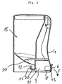
- An inventive dispenser according to Fig. 1 for sweetener tablets has a dispenser housing 1, the lower edge 2 forms a footprint. This is parallel to a dashed bottom 3, on which the donor stands up.
- the dispenser housing 1 comprises a in the FIG. 1 unspecified reservoir, from which the sweetener tablets by means of an output mechanism and be transported by pressing a side button 4 to a lower-side discharge opening.
- a laterally arranged on the bottom of the housing tab 6 is part of a tamper-evident closure.
- the tab 6 extends substantially parallel to the housing wall and is also formed slightly curved due to the rounded shape of the housing. At its end facing away from the lower footprint end, the tab has a more projecting from the housing or the side button 4 area 7, over which the key can be better grasped.
- the side key 4 is movable after violation of the originality at least with a component of movement in a direction transverse to a vertical standing on the lower Aufstandebene perpendicular (direction R).
- Fig. 2 is the tab via a web 8, which through a recess 10 ( Fig. 3 ) of the dispenser housing 1, arranged integrally on a belonging to the button 4, movable part 9 of the dispensing mechanism. If the originality is intact, movement of the side button will be blocked by the stopper on the housing.
- the flap itself acts as a blocking element.
- a lower housing part 13 thus acts as a stop for the blockade element or the tab 6.
- the side button and the associated, moving parts act here in combination with the fixed webs 20 of the donor as output mechanism.
- the tab 6, the web 8 and the housing part 13 act as a tamper-evident closure.
- the web can selectively have predetermined breaking points at which it can be destroyed in order to remove the blocking element.
- the tab 6 can also be made larger, not only to cover a lower part of the housing 1 (see Fig. 3 ), but also to overlap parts of the surface of the side key 4.
- the embodiment of FIGS. 1 to 3 has an approximately cross-sectionally teardrop-shaped form with two opposite narrow sides and two longitudinal sides. The cross-section is formed by a section transverse to a vertical 5, which is perpendicular to the lower Aufstandsebene 3.
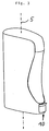
- the side key 4 is located on the narrower of the two narrow sides, both of these sides are rounded, while the long sides substantially straight, for representing a pleasant feel at best slightly curved or adapted to the hand anatomy. Overall, both the shown as well as other donors are formed by these features like a handle or formed. Similarly, the donor is the Fig. 5 formed, but here the side button is arranged on the wider of the two narrow sides.
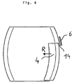
- FIG. 4 An outside of the housing is also the example of Fig. 4 as a stop for a removable before first removal tab 6, which is attached to a side button 4 of the example shown there. Only after bending the tab 6, which is connected via a predetermined breaking point which is integrated in a web 14, an actuation of the side key 4 in the direction R is released.
- the side button provided for actuation is covered by a blocking element 16 aligned with the rest of the housing 1. This is integrally formed with the housing and connected via predetermined breaking points 17 to the housing 1. A kinking of the blocking element 16 in the in the FIG. 6 shown direction F leads to a release of the side key 4 and a break of the originality.
- the lateral surface A of the side button 4 is completely covered in the originality case, so that a malfunction is effectively avoided.
- Fig. 7 is an embodiment of the Fig. 4 similar item, but having a different tamper-evident closure.
- the dispenser has here as a blocking element on a flap 21 which is integrally connected via a film hinge 22 with the key 4.
- a blocking element on a flap 21 which is integrally connected via a film hinge 22 with the key 4.
- the Fault line 22 shows a separation of the view between a partially cut, broken view and a non-broken view.
- the side button 4 By pressing the side button 4, this is pressed over a length in the housing, which allows slipping behind the damper 21 behind a housing wall 24 ( Fig. 8 ).
- the film hinge 22 thus has a certain recoil force, which allows a high speed of the flap no longer sliding on a projection 26 along 21. If, in particular, the part of the flap 21 which is now in contact with the inside of the housing or on the wall 21 is additionally color-coded and thus stands out from the rest of the housing, the violation of the originality is particularly clearly visible.
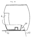
- Fig. 9 and 10 show tamper-evident closures or side-key dispensers in which a dispensing opening 27 is provided by placing a blocking element 28 in the opening 27 (FIG. Fig. 9 ) or through a cover of the opening ( Fig. 10 ) is closed and so an output of the estate is blocked.
- the blocking element 28 is connected via a web to a tab or a handle part 29 and can be broken out of the opening via the actuation of the tab 29 or the associated web
- the opening is closed by a film solution 31 as a blocking element or a similar-thin cover.
- this is a label 31, which is glued to the underside of the housing and can be deducted.
- Lines 23 again show in the figures the separation between broken and unbroken part of the dispenser.
- the keys used may be fixed or even to a small extent flexible element of a dispenser according to the invention, via the actuation of which the dispensing mechanism is moved.
Landscapes
- Engineering & Computer Science (AREA)
- Mechanical Engineering (AREA)
- Closures For Containers (AREA)
Description
- Die vorllegende Erfindung betrifft einen Gegenstand nach dem Oberbegriff des Anspruchs 1.
- Aus der
DE 20 2007 013 517 U1 ist ein Spender für Tabletten od.dgl. stückiges Gut bekannt, der ein Spendergehäuse mit einer unteren Aufstandsfläche und in seinem Gehäuse einen Vorratsraum zur Bevorratung des Guts aufweist. Aus diesem wird das auszugebende Gut mittels einer Ausgabemechanik zu einer zumindest im Betätigungsfall vorhandenen Ausgabeöffnung überführt, wobei der Spender zur Betätigung der Ausgabemechanik eine dieser zugeordnete, bewegliche Taste sowie zur Blockade der Betätigung vor der erstmaligen Ausgabe des Guts einen Originalitätsverschluss aufweist. Ein solcher Spender wird von Personen in der Regel mit dem Daumen betätigt. Es hat sich allerdings gezeigt, dass eine Reihe von Verwendern eine Betätigung mit dem Daumen als umständlich ansehen. Dies auch aufgrund der Notwendigkeit, einerseits mit der Hand zu greifen und anderseits den Daumen der gleichen Hand zu betätigen. - Die
DE 91 06 050 U1 offenbart einen Tablettenspender mit Originalitätssicherung, bei der die Lage und Richtung von am Behälterteil und Deckel eingeformten Vertiefungen dergestalt bestimmt ist, dass ein Originalitätsband den Deckel und den Spenderschieber sowie die Tablettenausfallöffnung abdeckt. Dieses Originalitätsband ist über die gesamte Höhe des Spenders umlaufend angeordnet und überdeckt die auf der Unterseite angeordnete Ausgabeöffnung. - In der
DE 42 01 995 A1 ist ein mit einem seitlichen Taster versehenen Tablettenspender beansprucht, bei der die Vereinzelungsvorrichtung über ein Sperrstück verriegelt ist, welches durch erhöhten Druck auf die Taste gegen den Widerstand einer Sperre überwunden werden kann. Die Sperre und das hiermit zusammenwirkende Widerlager sind an der unteren Seite des Tablettenspenders als Teil der Ausgabemechanik ausgebildet. - Die
WO 2004/000703 A1 offenbart einen Tablettenspender mit einer Vereinzelungsmechanik, deren unteres Ende über ein mit einer Lasche versehenes, kreuzförmiges Originalitätselement abgeschlossen werden kann. Durch Zug an der Lasche kann das Originalitätselement vom Tablettenspender abgezogen und entfernt werden. - Es ist Aufgabe der vorliegenden Erfindung, einen Spender mit einer alternativen Bedienrichtung zur Verfügung zu stellen.
- Die Aufgabe wird gelöst durch einen Gegenstand gemäß Anspruch 1. Weitere vorteilhafte Ausgestaltungen der Erfindung sind der nachfolgenden Beschreibung sowie den auf den Anspruch 1 rückbezogenen Unteransprüchen zu entnehmen.
- Erfindungsgemäß ist vorgesehen, dass die zu betätigende Taste des Spenders als Seitentaste ausgebildet ist, die nach Verletzung der Originalität mit zumindest einer Bewegungskomponente in eine Richtung quer zu einer auf der unteren Aufstandsfläche stehenden Senkrechten beweglich ist. Gleichzeitig weist der Originalitätsverschluss ein Blockadeelement auf, welches vor Verletzung der Originalität eine Betätigung der Seitentaste oder eine Ausgabe des Guts blockiert. Einerseits ist die Betätigung des Spenders zu den Fingern hin ausgerichtet, die ohnehin bereits den Spender mit umgreifen. Es sind weniger Finger zum Ausgeben des Gutes zu koordinieren, was gerade bei Personen mit eingeschränkter Mobilität vorteilhaft ist. Die Ausgabe des Guts kann durch dieselbe Bewegung erfolgen, mit der auch das Greifen des Spenders erfolgt. Darüber hinaus ist der Originalitätsverschluss zur vorherigen Blockade einer Betätigung dieser Seitentaste oder einer Ausgabe des Guts ausgebildet, so dass eine unbeabsichtigte Betätigung des Spenders während oder vor dem Verkauf ausgeschlossen werden kann. Zwecks einfacherer Handhabung kann ein betätigbarer Bereich des Originalitätsverschlusses ebenfalls in einem Seitenbereich in der Nähe oder unmittelbar bei einer Seitentaste angeordnet werden, insbesondere bezüglich einer Vertikalen auf einer unteren Aufstandsfläche in der unteren Hälfte des Spenders. Das Blockadeelement wirkt einer Relativbewegung von Seitentaste und einem relativ hierzu beweglichen weiteren Teil des Spenders entgegen oder verschließt mechanisch eine Ausgabeöffnung, die vorzugsweise auf der Unterseite des Spenders angeordnet ist, jedoch auch im unteren, seitlichen Randbereich des Gehäuses angeordnet sein kann.
- Bei einem vorteilhaften Ausführungsbeispiel deckt das Blockadeelement die Seitentaste dergestalt ab, dass zumindest ein Teil einer sonst zur Entnahme des Guts betätigbaren Oberfläche der Seitentaste ohne Entfernen des Blockadeelements unzugänglich für eine Betätigung mit einem Finger ist. Dies kann insbesondere durch eine Positionierung des Blockadeelements realisiert werden, welches in Bezug auf eine zentrale und vertikale Längsmittelachse des Spenders weiter außen angeordnet als die Seitentaste bzw. als Teile der Seitentaste. Besonders vorteilhaft kann das Blockadeelement die Seitentaste seitlich bezogen auf die zur Betätigung der Seitentaste vorgesehene Oberfläche zumindest zu 50%, vorzugsweise vollständig, abdecken.
- Vorteilhafterweise erstreckt sich die Seitentaste nicht über die komplette Höhe des Spenders sondern deckt einen Bereich zwischen 25% und 100% der Höhe des als Seitentastenspender ausgebildeten Spenders (bezogen wiederum auf eine Senkrechte auf der unteren Aufstandsebene bzw. -fläche) ab. Alternativ oder auch gleichzeitig ist die Seitentaste vorzugsweise und hauptsächlich auf einer Schmalseite eines in einer Draufsicht entlang der vorbeschriebenen Vertikalen oval, tropfenförmig oder dergleichen unrund ausgebildeten Form versehenen Spenders angeordnet, wobei der Spender mit zwei einander gegenüberliegenden, gebogenen Schmalseiten und im Wesentlichen gerade verlaufenden, längeren Längsseiten versehen sein kann. Eine solche Form schmiegt sich gut in eine Hand ein. Des Weiteren ist es möglich, z.B. zwei Finger zur Betätigung der Seitentaste zu verwenden und zwei Finger sowie den Daumen zum Halten des Spenders zu verwenden. Hierfür ist die Seitentaste vorzugsweise zumindest 18 mm hoch, während die Seitentaste nicht über die komplette Höhe des Spenders ausgebildet ist.
- Insbesondere durch eine vollständige Abdeckung der Seitentaste mittels eines beispielsweise mit dem Gehäuse längs dessen Außenseiten fluchtenden Blockadeelements, wird eine ungewünschte Betätigung des Blockadeelements wirkungsvoll verhindert. Gleichzeitig weist ein solcher Spender eine angenehme optische Erscheinung auf.
- Das Blockadeelement ist vorzugsweise sowohl in Varianten, die Teile der zu betätigenden Seitentaste abdecken, sowie in anderen Ausführungsbeispielen, in denen das Blockadeelement tatsächlich eine Bewegung der Seitentaste durch einen Anschlag od.dgl. blockiert über zumindest eine Sollbruchstelle mit einem nach Aufbrechen der Originalität relativ zur Seitentaste beweglichen Teil des Spenders einstückig verbunden. Bei dieser Variante des Spenders kann das Blockadeelement beispielsweise einstückig mit dem Gehäuse und somit vor Einsetzen einer Spendermechanik ausgebildet werden.
- Um eine Anbindung eines Originalitätsverschlusselements, z.B. des Blockadeelements an den Spender einfach zu realisieren, gleichzeitig jedoch eine Betätigung des Originalitätsverschlusses im Bereich eines Außenumfangs des Spenders zu ermöglichen, ist dieser erfindungsgemäß mit einem insbesondere eine Ausnehmung des Gehäuses durchgreifenden oder durch diese hindurchführenden Steg versehen. Ein solcher Steg, der auf einfache Weise auch eine Sollbruchstelle durch eine entsprechende Dünnstelle oder durch Abknicken an bestimmten Anschlägen des Gehäuses ausbilden kann, ist einfach herstellbar und kann innerhalb des Gehäuses entweder an beweglichen Teilen der Ausgabemechanik bzw. an festen Gehäuseteilen, die die Ausgabemechanik aufnehmen, festgelegt werden. Durch ein Herausführen aus dem Gehäuseinneren ist der Steg dann dass Verbindungsglied zu einem manuell betätigbaren Teil des Originalitätsverschlusses. Insbesondere ist der Steg durch Betätigung einer mit dieser verbundenen Lasche abknickbar.
- In einem Ausführungsbeispiel mit einer Ausnehmung, die vom Steg durchgriffen wird, bzw. durch die der Steg hindurchführt, kann diese auch einseitig offen sein, so dass ein entsprechender Steg bei Einschieben einer Ausgabemechanik durch eine untere Öffnung des Gehäuses von dieser Seite kommend mit eingeschoben werden kann. Beispielsweise handelt es sich somit bei der Ausnehmung um eine von der Unterseite des Gehäuses ausgehende Nut.
- Eine manuell zu betätigende Lasche, die Teil des Originalitätsverschlusses ist und seitlich des Gehäuses angeordnet ist, ist besonders vorteilhaft, da diese Lasche dann auch gleich im Bereich der eigentlich zu betätigenden Seitentaste angeordnet sein kann. Es kann sich also um eine Lasche handeln, die die seitliche Tasche abdeckt bzw. die unmittelbar in deren Nähe angeordnet ist und die entweder selbst ein Blockadeelement darstellt oder über die ein Blockadeelement entfernbar ist.
- Der erfindungsgemäße Seitentastenspender zeichnet sich vorzugsweise dadurch aus, dass der Originalitätsverschluss separat betätigt werden muss, um eine Ausgabe des Guts zu bewirken.
- Vorzugsweise befindet sich die Lasche am unteren Ende der an ihrem oberen Ende schwenkbar festgelegten Seitentaste, da dort ein Bereich eines größten Hubs bzw. einer größten Verlagerung der Seitentaste ist und in den hierfür notwendigen Freiräumen ein Blockadeelement am ehesten angebracht werden kann.
- Vorzugsweise kann durch Betätigung der Lasche ein Steg, über den diese angebunden ist, gerade auch bei einer am unteren Rand des Gehäuses befindlichen Ausnehmung, zumindest in Teilen nach unten weg- oder abknickbar gestaltet sein, so dass etwaige, die Betätigung der Seitentaste blockierende Elemente des Originalitätsverschlusses aus dem Bewegungsbereich der Seitentaste heraus verschwenkt werden können und somit die Taste freigegeben werden kann.
- Zur besseren Greifbarkeit einer etwaigen Lasche ist diese an ihrem von der unteren Aufstandsfläche wegweisenden Ende weiter von dem Gehäuse oder der Seitentaste des Spenders abstehend ausgebildet als an ihrem diesem Ende entgegengesetzten Ende.
- Die Integration des Originalitätsverschlusses bei Einbringen der Schiebermechanik ist insbesondere dann verbessert, wenn das Blockadeelement über zumindest eine Sollbruchstelle mit der Seitentaste oder einem von dieser bewegten Teil des Spenders einstückig verbunden ist. Dies ist vor allem dann vorteilhaft, wenn die Mechanik des Spenders bei Fertigung desselben von unten über die untere Aufstandsfläche hindurch in das Gehäuse eingeschoben werden kann.
- Eine solche Sollbruchstelle ist vorzugsweise innerhalb eines äußeren Umfangs des Gehäuses des Spenders angeordnet, so dass eine Manipulation des Spenders verhindert werden kann. Außerdem können dann durch die Sollbruchstelle entstehende scharfe Kanten od.dgl. weniger erreichbar sein, als dies beispielsweise im Stand der Technik der Fall ist.
- Ein nicht-erfindungsgemäßer Originalitätsverschluss kann einen in die Seitentaste oder das Gehäuse eindrückbaren Anschlag aufweisen, der als Blockadeelement dient. Bei diesem Anschlag sowie bei den sonstigen Blockadeelementen kann der Originalitätsverschluss eine die Verletzung der Originalität aufzeigende Klappe umfassen, die insbesondere über ein Filmscharnier oder eine andere Dünnstelle mit der Seitentaste verbunden ist und sich nach Betätigung der Seitentaste und Verletzung der Originalität in eine diese Verletzung kennzeichnende Stellung bewegt. Die Klappe kann ebenfalls selbst das Blockadeelement darstellen.
- Alternativ oder ergänzend kann der Originalitätsverschluss als Blockadeelement einen Anschlag aufweisen, der gegen eine innenliegende Wand der Seitentaste ansteht und durch Betätigung des Originalitätsverschlusses, beispielsweise Wegbiegen einer außenliegenden und nach unten entfernbaren Lasche, aus der Blockadeposition entfernbar ist. Hierzu kann insbesondere eine Lasche verwendet werden, die mittels eines eine Ausnehmung durchgreifenden Stegs innerhalb des Außenumfangs des Spenders angebunden ist.
- Ebenfalls kann das Blockadeelement des Originalitätsverschlusses dergestalt ausgebildet sein, dass es die Ausgabeöffnung mechanisch verschließt, also z.B. abdeckt. Auch kann es in dieser angeordnet sein. Ergänzend kann insbesondere bei einer Anordnung in der Ausgabeöffnung das Blockadeelement als Anschlag ausgebildet sein.
- Weitere Vorteile und Einzelheiten der Erfindung lassen sich der nachfolgenden Figurenbeschreibung entnehmen. In den schematischen Abbildungen der Figuren zeigt:
- Fig. 1:
- eine Seitenansicht eines erfindungsgemäßen Spenders,
- Fig. 2:
- den Gegenstand nach
Fig. 1 in einer Schnittdarstellung, - Fig. 3:
- den Gegenstand nach
Fig. 1 in einer perspektivischen Darstellung, - Fig. 4:
- ein weiteres nicht-erfindungsgemäßen Beispiel in einer Seitenansicht,
- Fig. 5:
- ein weiteres nicht-erfindungsgemäßen Beispiel in einer perspektivischen Darstellung,
- Fig. 6:
- den Gegenstand nach
Fig. 5 mit teilweise aufgebrochener Originalität, - Fig. 7
- eine teilweise geschnittene Ansicht eines weiteren nicht-erfindungsgemäßen Beispiels,
- Fig. 8
- den Gegenstand nach
Fig. 7 in einer Position nach Verletzung der Originalität, - Fig. 9
- ein weitere nicht-erfindungsgemäßes Beispiel,
- Fig. 10
- ein weiteres nicht-erfindungsgemäßes Beispiel.
- Gleich oder ähnlich wirkende Teile sind - sofern dienlich - mit identischen Bezugsziffern versehen. Einzelne technische Merkmale der nachfolgend beschriebenen Ausführungsbeispiele können auch mit den Merkmalen der vorbeschriebenen Ausführungsbeispiele zu erfindungsgemäßen Weiterbildungen führen.
- Ein erfindungsgemäßer Spender gemäß
Fig. 1 für Süßstofftabletten weist ein Spendergehäuse 1 auf, dessen unterer Rand 2 eine Aufstandsfläche ausbildet. Diese liegt parallel zu einem gestrichelt dargestellten Boden 3, auf dem der Spender aufsteht. - Das Spendergehäuse 1 umfasst einen in der
Figur 1 nicht näher erkennbaren Vorratsraum, von dem aus die Süßstofftabletten mittels einer Ausgabemechanik und durch Betätigung einer Seitentaste 4 zu einer unterseitigen Ausgabeöffnung transportiert werden. Eine seitlich unten am Gehäuse angeordnete Lasche 6 ist Teil eines Originalitätsverschlusses. Die Lasche 6 erstreckt sich im Wesentlichen parallel zur Gehäusewand und ist aufgrund der gerundeten Form des Gehäuses ebenfalls leicht gebogen ausgebildet. An ihrem von der unteren Aufstandsfläche wegweisenden Ende weist die Lasche einen stärker vom Gehäuse beziehungsweise der Seitentaste 4 abstehenden Bereich 7 auf, über den die Taste besser gegriffen werden kann. - Die Seitentaste 4 ist nach Verletzung der Originalität zumindest mit einer Bewegungskomponente in eine Richtung quer zu einer auf der unteren Aufstandebene stehenden Senkrechten beweglich (Richtung R).
- Gemäß
Fig. 2 ist die Lasche über einen Steg 8, der durch eine Ausnehmung 10 (Fig. 3 ) des Spendergehäuses 1 hindurchführt, einstückig an einem zur Taste 4 gehörenden, beweglichen Teil 9 der Ausgabemechanik angeordnet. Bei intakter Originalität wird durch den Anschlag der Lasche am Gehäuse eine Bewegung der Seitentaste blockiert. Die Lasche selbst wirkt als Blockadeelement. Durch Bewegen der Lasche 6 in die in derFig. 2 gezeigte Richtung F knickt diese ab, so dass die Taste 4 bei Betätigung nicht mehr durch die als Blockadeelement wirkende Lasche an das Gehäuse anschlägt. Vielmehr ist der Ausgabeweg frei, um durch Versetzen der beiden Stege 11 und gleichzeitiges Mitführen einer Süßstofftablette 12 diese aus einem Vorratsraum 15 kommend durch eine dann ausgebildete Öffnung nach unten wegfallen kann. Ein unterer Gehäuseteil 13 wirkt somit als Anschlag für das Blockadeelement respektive die Lasche 6. Die Seitentaste sowie die hiermit verbundenen, beweglichen Teile wirken hier in Kombination mit den feststehenden Stegen 20 des Spenders als Ausgabemechanik. Die Lasche 6, der Steg 8 und der Gehäuseteil 13 wirken als Originalitätsverschluss. - Durch Vorsehen einer oder mehrerer Dünnstellen im Bereich zwischen Lasche 6 und dem Teil 9 kann der Steg gezielt Sollbruchstellen aufweisen, an denen er zerstört werden kann, um das Blockadeelement zu entfernen.
- Die Lasche 6 kann auch größer ausgebildet werden, um nicht nur einen unteren Teil des Gehäuses 1 abzudecken (vergleiche
Fig. 3 ), sondern auch um Teile der Oberfläche der Seitentaste 4 zu übergreifen. Das Ausführungsbeispiel derFiguren 1 bis 3 weist eine im Querschnitt angenähert tropfenförmige Form auf mit zwei einander gegenüberliegenden Schmalseiten und zwei Längsseiten. Der Querschnitt ist gebildet durch einen Schnitt quer zu einer Senkrechten 5, die senkrecht zu der unteren Aufstandsebene 3 steht. Die Seitentaste 4 befindet sich auf der schmaleren der beiden Schmalseiten, beide diese Seiten sind gerundet ausgebildet, während die Längsseiten im Wesentlichen gerade, zur Darstellung einer angenehmeren Haptik allenfalls leicht gewölbt oder an die Handanatomie angepasst verlaufen können. Insgesamt sind sowohl der gezeigte wie auch andere Spender durch diese Merkmale griffartig ausgebildet bzw. ausbildbar. Ähnlich ist auch der Spender derFig. 5 ausgebildet, wobei hier allerdings die Seitentaste auf der breiteren der beiden Schmalseiten angeordnet ist. - Eine Außenseite des Gehäuses dient auch dem Beispiel der
Fig. 4 als Anschlag für eine vor erstmaliger Entnahme zu entfernende Lasche 6, die an einer Seitentaste 4 des dort gezeigten Beispiels befestigt ist. Erst nach Abknicken der Lasche 6, die über eine Sollbruchstelle, die in einem Steg 14 integriert ist, angebunden ist, wird eine Betätigung der Seitentaste 4 in Richtung R freigegeben. - Im Beispiel der
Fig. 5 ist die zur Betätigung vorgesehene Seitentaste durch ein mit dem Rest des Gehäuses 1 fluchtendes Blockadeelement 16 abgedeckt. Dieses ist einstückig mit dem Gehäuse ausgebildet und über Sollbruchstellen 17 mit dem Gehäuse 1 verbunden. Ein Abknicken des Blockadeelementes 16 in die in derFigur 6 gezeigte Richtung F führt zu einer Freigabe des Seitentaste 4 und einem Aufbrechen der Originalität. - Bei diesem Beispiel ist die seitliche Fläche A der Seitentaste 4 im Originalitätsfall komplett abgedeckt, sodass eine Fehlbedienung wirkungsvoll vermieden wird.
- Im Beispiel der
Fig. 7 ist ein dem Ausführungsbeispiel derFig. 4 ähnlicher Gegenstand gezeigt, der allerdings einen anderen Originalitätsverschluss aufweist. - Der Spender weist-hier als Blockadeelement eine Klappe 21 auf, die über ein Filmscharnier 22 einstückig mit der Taste 4 verbunden ist. In der Ansicht ist entlang der Bruchlinie 22 eine Trennung der Ansicht zwischen einer teilweise geschnittenen, aufgebrochenen Ansicht und einer nicht aufgebrochenen Ansicht dargestellt.
- Durch Betätigung der Seitentaste 4 wird diese über eine Länge in das Gehäuse eingedrückt, die ein Hinterrutschen der Klappe 21 hinter eine Gehäusewand 24 ermöglicht (
Fig. 8 ). Das Filmscharnier 22 weist somit eine gewisse Rückschnellkraft auf, die ein Hochschnellen der nicht mehr an einem Vorsprung 26 entlang gleitenden Klappe 21 ermöglicht. Sofern insbesondere der nun an der Innenseite des Gehäuses bzw. an der Wand 21 anliegende Teil der Klappe 21 farblich noch besonders gekennzeichnet ist und sich so vom Rest des Gehäuses abhebt, ist die Verletzung der Originalität besonders deutlich sichtbar. - Die Beispiele der
Fig. 9 und10 zeigen Originalitätsverschlüsse bzw. Seitentastenspender, bei denen eine Ausgabeöffnung 27 durch Anordnung eines Blockadeelements 28 in der Öffnung 27 (Fig. 9 ) oder durch eine Abdeckung der Öffnung (Fig. 10 ) verschlossen ist und so eine Ausgabe des Guts blockiert wird. - Während in dem Beispiel der
Fig. 9 das Blockadeelement 28 über einen Steg mit einer Lasche bzw. einem Griffteil 29 verbunden ist und über die Betätigung der Lasche 29 bzw. des zugehörigen Stegs aus der Öffnung heraus gebrochen werden kann, ist in derFig. 10 die Öffnung durch eine Folienlösung 31 als Blockadeelement bzw. eine ähnlich-dünne Abdeckung verschlossen. Insbesondere handelt es sich hierbei um ein Etikett 31, welches an die Unterseite des Gehäuses geklebt ist und abgezogen werden kann. - Linien 23 zeigen in den Figuren wiederum die Trennung zwischen aufgebrochenem und nicht aufgebrochenem Teil des Spenders.
- Generell kann es sich bei den verwendeten Tasten um feste oder auch um in einem geringen Maß flexibles Element eines erfindungsgemäßen Spenders handeln, über dessen Betätigung die Ausgabemechanik bewegt wird.
Claims (12)
- Spender für Tabletten oder dgl. stückiges Gut (12), mit einem in einem mit einer unteren Aufstandsfläche versehenen Spendergehäuse (1) angeordneten und zur Bevorratung des Guts (12) vorgesehenen Vorratsraum (15), von dem auszugebendes Gut (12) mittels einer Ausgabemechanik zu einer zumindest im Betätigungsfall vorhandenen Ausgabeöffnung überführbar ist, wobei der Spender zur Betätigung der Ausgabemechanik eine dieser zugeordnete, bewegliche Taste (4) sowie zur Blockade der Ausgabe des Guts (12) und/oder Kenntlichmachung des Benutzungszustands einen Originalitätsverschluss aufweist, wobei die Taste (4) als Seitentaste ausgebildet ist, die nach Verletzung der Originalität zumindest mit einer Bewegungskomponente (R) in eine Richtung quer zu einer auf der unteren Aufstandsfläche stehenden Senkrechten beweglich ist, und der Originalitätsverschluss ein Blockadeelement (6, 16, 21, 28, 31) aufweist, welches eine Betätigung der Seitentaste oder eine Ausgabe des Guts vor Verletzung der Originalität blockiert, wobei der Originalitätsverschluss einen insbesondere eine Ausnehmung (10) des Gehäuses (1) durchgreifenden Steg (8) aufweist, dadurch gekennzeichnet, dass der Originalitatsverschluss eine seitlich des Gehäuses (1) befindliche Lasche (6) umfasst, die sich am unteren Ende der an ihren oberen Ende schwenkbar festgelegten Seitentaste befindet.
- Spender nach Anspruch 1, dadurch gekennzeichnet, dass das Blockadeelement (16) die Seitentaste dergestalt abdeckt, dass zumindest ein Teil einer sonst zur Entnahme des Guts (12) betätigbaren Oberfläche (A) der Seitentaste ohne Entfernen des Blockadeelements unzugänglich für eine Betätigung mit einem Finger ist.
- Spender nach Anspruch 2, dadurch gekennzeichnet, dass das Blockadeelement (16) die Seitentaste seitlich bezogen auf die zur Betätigung der Seitentaste vorgesehene Oberfläche (A) zumindest zu 50 %, vorzugsweise vollständig abdeckt.
- Spender nach einem der vorherigen Ansprüche, dadurch gekennzeichnet, dass das Blockadeelement (16) über wenigstens eine Sollbruchstelle (17) mit einem nach Aufbrechen der Originalität relativ zur Seitentaste beweglichen Teil des Spenders einstückig verbunden ist.
- Spender nach einem der vorherigen Ansprüche, dadurch gekennzeichnet, dass der Steg (8) abknickbar durch Betätigung der Lasche (6) ausgebildet ist.
- Spender nach Anspruch 5, dadurch gekennzeichnet, dass der Steg (8) durch Betätigung der Lasche zumindest in Teilen nach unten weg knickbar ist.
- Spender nach einem der vorherigen Ansprüche dadurch gekennzeichnet, dass die Lasche an ihrem von der unteren Aufstandsfläche weg weisenden Ende zur besseren Greifbarkeit weiter von dem Gehäuse (1) oder der Seitentaste des Spenders absteht als an ihrem diesem Ende entgegengesetzten Ende.
- Spender nach einem der vorherigen Ansprüche, dadurch gekennzeichnet, dass das Blockadeelement (6) über zumindest eine Sollbruchstelle mit der Seitentaste oder einem von dieser bewegten Teil (9) des Spenders einstückig verbunden ist.
- Spender nach Anspruch 8, dadurch gekennzeichnet, dass die Sollbruchstelle innerhalb eines äußeren Umfangs des Gehäuses (1) des Spenders oder des Spenders angeordnet ist.
- Spender nach einem der vorherigen Ansprüche, dadurch gekennzeichnet, dass der Originalitätsverschluss einen in die Seitentaste oder das Gehäuse (1) eindrückbaren Anschlag aufweist.
- Spender nach einem der vorherigen Ansprüche, dadurch gekennzeichnet, dass der Originalitätsverschluss als Blockadeelement einen Anschlag aufweist, der gegen eine innenliegende Wand der Seitentaste ansteht und durch Betätigung des Originalitätsverschlusses aus der Blockadeposition entfernbar ist.
- Spender nach einem der vorherigen Ansprüche, dadurch gekennzeichnet, dass das Blockadeelement die Ausgabeöffnung verschließt und insbesondere in dieser angeordnet ist.
Applications Claiming Priority (2)
| Application Number | Priority Date | Filing Date | Title |
|---|---|---|---|
| DE202012003294U DE202012003294U1 (de) | 2012-03-30 | 2012-03-30 | Spender |
| PCT/EP2013/000932 WO2013143697A1 (de) | 2012-03-30 | 2013-03-27 | Spender |
Publications (2)
| Publication Number | Publication Date |
|---|---|
| EP2830975A1 EP2830975A1 (de) | 2015-02-04 |
| EP2830975B1 true EP2830975B1 (de) | 2016-07-27 |
Family
ID=48141893
Family Applications (1)
| Application Number | Title | Priority Date | Filing Date |
|---|---|---|---|
| EP13717163.3A Active EP2830975B1 (de) | 2012-03-30 | 2013-03-27 | Spender |
Country Status (3)
| Country | Link |
|---|---|
| EP (1) | EP2830975B1 (de) |
| DE (1) | DE202012003294U1 (de) |
| WO (1) | WO2013143697A1 (de) |
Families Citing this family (1)
| Publication number | Priority date | Publication date | Assignee | Title |
|---|---|---|---|---|
| DE202019102862U1 (de) | 2019-05-21 | 2019-07-10 | Dr. Willmar Schwabe Gmbh & Co. Kg | Dosiervorrichtung |
Citations (2)
| Publication number | Priority date | Publication date | Assignee | Title |
|---|---|---|---|---|
| DE9106050U1 (de) | 1991-05-16 | 1991-07-18 | Fejervary, Tibor, Dr., 7500 Karlsruhe, De | |
| DE4201995A1 (de) | 1992-01-25 | 1993-07-29 | Kerplas Neuenburg Gmbh Kunstst | Spender fuer tablettenfoermige gegenstaende |
Family Cites Families (9)
| Publication number | Priority date | Publication date | Assignee | Title |
|---|---|---|---|---|
| US2943730A (en) * | 1958-07-29 | 1960-07-05 | Harold R Tregilgas | Pill dispenser |
| DE3320740A1 (de) * | 1982-05-12 | 1984-12-13 | Gerold 2081 Ellerbek Anderka | Vorratsbehaelter mit vorrichtung zum vereinzeln von tabletten |
| DE9106254U1 (de) * | 1991-05-21 | 1991-07-18 | Gallina, Ramona, 7805 Boetzingen, De | |
| DE9217555U1 (de) * | 1992-12-22 | 1994-05-05 | Jaco Praezision Dr Jaeniche | Behältnis zur einzelportionierten Ausgabe von Tabletten o.dgl. |
| AUPQ933700A0 (en) * | 2000-08-10 | 2000-08-31 | Western Research & Development Pty Ltd | Tamper proof product dispenser |
| US6726058B2 (en) * | 2002-06-20 | 2004-04-27 | Csp Technologies, Inc. | Dispenser for solid objects |
| US20050236419A1 (en) * | 2004-04-22 | 2005-10-27 | Jason Moenikeij | Comestible product dispensers and methods of making and using same |
| ATE438575T1 (de) * | 2005-01-25 | 2009-08-15 | Reckitt Benckiser Healthcare | Spender |
| DE202007013517U1 (de) | 2007-09-27 | 2007-12-20 | Pöppelmann Holding GmbH & Co. KG | Spender o.dgl. Ausgabebehälter |
-
2012
- 2012-03-30 DE DE202012003294U patent/DE202012003294U1/de not_active Expired - Lifetime
-
2013
- 2013-03-27 EP EP13717163.3A patent/EP2830975B1/de active Active
- 2013-03-27 WO PCT/EP2013/000932 patent/WO2013143697A1/de active Application Filing
Patent Citations (2)
| Publication number | Priority date | Publication date | Assignee | Title |
|---|---|---|---|---|
| DE9106050U1 (de) | 1991-05-16 | 1991-07-18 | Fejervary, Tibor, Dr., 7500 Karlsruhe, De | |
| DE4201995A1 (de) | 1992-01-25 | 1993-07-29 | Kerplas Neuenburg Gmbh Kunstst | Spender fuer tablettenfoermige gegenstaende |
Also Published As
| Publication number | Publication date |
|---|---|
| EP2830975A1 (de) | 2015-02-04 |
| WO2013143697A1 (de) | 2013-10-03 |
| DE202012003294U1 (de) | 2013-07-01 |
Similar Documents
| Publication | Publication Date | Title |
|---|---|---|
| DE60111201T2 (de) | Inhalator | |
| EP2193087B1 (de) | Spender oder dergleichen ausgabebehälter | |
| EP0761563A1 (de) | Tablettenspender | |
| DE202005007205U1 (de) | Behälter mit einer Einrichtung zum Abgeben von Produkt | |
| EP2067718A1 (de) | Tablettendispenser | |
| WO2001047786A1 (de) | Spender zur ausgabe von streifenelementen | |
| DE202012007857U1 (de) | Verschlusskappe für einen Behälter | |
| DE60106392T2 (de) | Abgabevorrichtung mit greifereinrichtung | |
| DE60302349T2 (de) | Abgabevorrichtung für medien | |
| EP3131518B1 (de) | Mehrkammerbeutelöffnungshilfe | |
| DE102009044280A1 (de) | Produktspender | |
| EP2830975B1 (de) | Spender | |
| EP2945875A2 (de) | Kindergesicherter behälterverschluss | |
| EP2192310B1 (de) | Karabinerhaken | |
| EP2964544B1 (de) | Spender zur ausgabe eines materials aus einem behälter | |
| DE202005007204U1 (de) | Behälter mit einer Einrichtung zum Abgeben von Produkt | |
| EP0659391B1 (de) | Vorrichtung zur Portionierung von bandförmigem Material | |
| DE102004012470B4 (de) | Betätigungshandgriff für eine Ortschaumdose, sowie Kombination aus einer Ortschaumdose mit einem Betätigungshandgriff | |
| EP3027533B1 (de) | Spenderbox | |
| CH478699A (de) | Behälter mit einer Ausschubvorrichtung für Bonbons | |
| EP3459905A1 (de) | Kellnermesser | |
| DE102010063030A1 (de) | Spender zum Spenden einzeln geformter Produkte | |
| DE19630710C1 (de) | Tablettenspender mit einem äußeren Gehäuse und einem Behälter | |
| EP2261140A2 (de) | Sprühkappe für einen mit einem Abgabeventil versehenen Druckbehälter | |
| DE102015224626A1 (de) | Spender |
Legal Events
| Date | Code | Title | Description |
|---|---|---|---|
| PUAI | Public reference made under article 153(3) epc to a published international application that has entered the european phase |
Free format text: ORIGINAL CODE: 0009012 |
|
| 17P | Request for examination filed |
Effective date: 20141015 |
|
| AK | Designated contracting states |
Kind code of ref document: A1 Designated state(s): AL AT BE BG CH CY CZ DE DK EE ES FI FR GB GR HR HU IE IS IT LI LT LU LV MC MK MT NL NO PL PT RO RS SE SI SK SM TR |
|
| AX | Request for extension of the european patent |
Extension state: BA ME |
|
| DAX | Request for extension of the european patent (deleted) | ||
| GRAP | Despatch of communication of intention to grant a patent |
Free format text: ORIGINAL CODE: EPIDOSNIGR1 |
|
| INTG | Intention to grant announced |
Effective date: 20160307 |
|
| GRAS | Grant fee paid |
Free format text: ORIGINAL CODE: EPIDOSNIGR3 |
|
| GRAA | (expected) grant |
Free format text: ORIGINAL CODE: 0009210 |
|
| STAA | Information on the status of an ep patent application or granted ep patent |
Free format text: STATUS: THE PATENT HAS BEEN GRANTED |
|
| AK | Designated contracting states |
Kind code of ref document: B1 Designated state(s): AL AT BE BG CH CY CZ DE DK EE ES FI FR GB GR HR HU IE IS IT LI LT LU LV MC MK MT NL NO PL PT RO RS SE SI SK SM TR |
|
| REG | Reference to a national code |
Ref country code: GB Ref legal event code: FG4D Free format text: NOT ENGLISH |
|
| REG | Reference to a national code |
Ref country code: CH Ref legal event code: EP |
|
| REG | Reference to a national code |
Ref country code: AT Ref legal event code: REF Ref document number: 815602 Country of ref document: AT Kind code of ref document: T Effective date: 20160815 |
|
| REG | Reference to a national code |
Ref country code: IE Ref legal event code: FG4D Free format text: LANGUAGE OF EP DOCUMENT: GERMAN |
|
| REG | Reference to a national code |
Ref country code: DE Ref legal event code: R096 Ref document number: 502013003878 Country of ref document: DE |
|
| REG | Reference to a national code |
Ref country code: LT Ref legal event code: MG4D |
|
| REG | Reference to a national code |
Ref country code: NL Ref legal event code: MP Effective date: 20160727 |
|
| PG25 | Lapsed in a contracting state [announced via postgrant information from national office to epo] |
Ref country code: IT Free format text: LAPSE BECAUSE OF FAILURE TO SUBMIT A TRANSLATION OF THE DESCRIPTION OR TO PAY THE FEE WITHIN THE PRESCRIBED TIME-LIMIT Effective date: 20160727 Ref country code: NL Free format text: LAPSE BECAUSE OF FAILURE TO SUBMIT A TRANSLATION OF THE DESCRIPTION OR TO PAY THE FEE WITHIN THE PRESCRIBED TIME-LIMIT Effective date: 20160727 Ref country code: LT Free format text: LAPSE BECAUSE OF FAILURE TO SUBMIT A TRANSLATION OF THE DESCRIPTION OR TO PAY THE FEE WITHIN THE PRESCRIBED TIME-LIMIT Effective date: 20160727 Ref country code: NO Free format text: LAPSE BECAUSE OF FAILURE TO SUBMIT A TRANSLATION OF THE DESCRIPTION OR TO PAY THE FEE WITHIN THE PRESCRIBED TIME-LIMIT Effective date: 20161027 Ref country code: HR Free format text: LAPSE BECAUSE OF FAILURE TO SUBMIT A TRANSLATION OF THE DESCRIPTION OR TO PAY THE FEE WITHIN THE PRESCRIBED TIME-LIMIT Effective date: 20160727 Ref country code: IS Free format text: LAPSE BECAUSE OF FAILURE TO SUBMIT A TRANSLATION OF THE DESCRIPTION OR TO PAY THE FEE WITHIN THE PRESCRIBED TIME-LIMIT Effective date: 20161127 Ref country code: RS Free format text: LAPSE BECAUSE OF FAILURE TO SUBMIT A TRANSLATION OF THE DESCRIPTION OR TO PAY THE FEE WITHIN THE PRESCRIBED TIME-LIMIT Effective date: 20160727 Ref country code: FI Free format text: LAPSE BECAUSE OF FAILURE TO SUBMIT A TRANSLATION OF THE DESCRIPTION OR TO PAY THE FEE WITHIN THE PRESCRIBED TIME-LIMIT Effective date: 20160727 |
|
| PG25 | Lapsed in a contracting state [announced via postgrant information from national office to epo] |
Ref country code: PL Free format text: LAPSE BECAUSE OF FAILURE TO SUBMIT A TRANSLATION OF THE DESCRIPTION OR TO PAY THE FEE WITHIN THE PRESCRIBED TIME-LIMIT Effective date: 20160727 Ref country code: LV Free format text: LAPSE BECAUSE OF FAILURE TO SUBMIT A TRANSLATION OF THE DESCRIPTION OR TO PAY THE FEE WITHIN THE PRESCRIBED TIME-LIMIT Effective date: 20160727 Ref country code: PT Free format text: LAPSE BECAUSE OF FAILURE TO SUBMIT A TRANSLATION OF THE DESCRIPTION OR TO PAY THE FEE WITHIN THE PRESCRIBED TIME-LIMIT Effective date: 20161128 Ref country code: SE Free format text: LAPSE BECAUSE OF FAILURE TO SUBMIT A TRANSLATION OF THE DESCRIPTION OR TO PAY THE FEE WITHIN THE PRESCRIBED TIME-LIMIT Effective date: 20160727 Ref country code: GR Free format text: LAPSE BECAUSE OF FAILURE TO SUBMIT A TRANSLATION OF THE DESCRIPTION OR TO PAY THE FEE WITHIN THE PRESCRIBED TIME-LIMIT Effective date: 20161028 Ref country code: ES Free format text: LAPSE BECAUSE OF FAILURE TO SUBMIT A TRANSLATION OF THE DESCRIPTION OR TO PAY THE FEE WITHIN THE PRESCRIBED TIME-LIMIT Effective date: 20160727 |
|
| REG | Reference to a national code |
Ref country code: FR Ref legal event code: PLFP Year of fee payment: 5 |
|
| REG | Reference to a national code |
Ref country code: DE Ref legal event code: R026 Ref document number: 502013003878 Country of ref document: DE |
|
| PG25 | Lapsed in a contracting state [announced via postgrant information from national office to epo] |
Ref country code: RO Free format text: LAPSE BECAUSE OF FAILURE TO SUBMIT A TRANSLATION OF THE DESCRIPTION OR TO PAY THE FEE WITHIN THE PRESCRIBED TIME-LIMIT Effective date: 20160727 Ref country code: EE Free format text: LAPSE BECAUSE OF FAILURE TO SUBMIT A TRANSLATION OF THE DESCRIPTION OR TO PAY THE FEE WITHIN THE PRESCRIBED TIME-LIMIT Effective date: 20160727 |
|
| PLBI | Opposition filed |
Free format text: ORIGINAL CODE: 0009260 |
|
| 26 | Opposition filed |
Opponent name: RPC BRAMLAGE GMBH Effective date: 20170427 |
|
| PG25 | Lapsed in a contracting state [announced via postgrant information from national office to epo] |
Ref country code: SM Free format text: LAPSE BECAUSE OF FAILURE TO SUBMIT A TRANSLATION OF THE DESCRIPTION OR TO PAY THE FEE WITHIN THE PRESCRIBED TIME-LIMIT Effective date: 20160727 Ref country code: DK Free format text: LAPSE BECAUSE OF FAILURE TO SUBMIT A TRANSLATION OF THE DESCRIPTION OR TO PAY THE FEE WITHIN THE PRESCRIBED TIME-LIMIT Effective date: 20160727 Ref country code: SK Free format text: LAPSE BECAUSE OF FAILURE TO SUBMIT A TRANSLATION OF THE DESCRIPTION OR TO PAY THE FEE WITHIN THE PRESCRIBED TIME-LIMIT Effective date: 20160727 Ref country code: CZ Free format text: LAPSE BECAUSE OF FAILURE TO SUBMIT A TRANSLATION OF THE DESCRIPTION OR TO PAY THE FEE WITHIN THE PRESCRIBED TIME-LIMIT Effective date: 20160727 Ref country code: BG Free format text: LAPSE BECAUSE OF FAILURE TO SUBMIT A TRANSLATION OF THE DESCRIPTION OR TO PAY THE FEE WITHIN THE PRESCRIBED TIME-LIMIT Effective date: 20161027 |
|
| PLAX | Notice of opposition and request to file observation + time limit sent |
Free format text: ORIGINAL CODE: EPIDOSNOBS2 |
|
| PG25 | Lapsed in a contracting state [announced via postgrant information from national office to epo] |
Ref country code: SI Free format text: LAPSE BECAUSE OF FAILURE TO SUBMIT A TRANSLATION OF THE DESCRIPTION OR TO PAY THE FEE WITHIN THE PRESCRIBED TIME-LIMIT Effective date: 20160727 |
|
| PLBB | Reply of patent proprietor to notice(s) of opposition received |
Free format text: ORIGINAL CODE: EPIDOSNOBS3 |
|
| REG | Reference to a national code |
Ref country code: CH Ref legal event code: PL |
|
| GBPC | Gb: european patent ceased through non-payment of renewal fee |
Effective date: 20170327 |
|
| PG25 | Lapsed in a contracting state [announced via postgrant information from national office to epo] |
Ref country code: MC Free format text: LAPSE BECAUSE OF FAILURE TO SUBMIT A TRANSLATION OF THE DESCRIPTION OR TO PAY THE FEE WITHIN THE PRESCRIBED TIME-LIMIT Effective date: 20160727 |
|
| REG | Reference to a national code |
Ref country code: IE Ref legal event code: MM4A |
|
| PG25 | Lapsed in a contracting state [announced via postgrant information from national office to epo] |
Ref country code: LU Free format text: LAPSE BECAUSE OF NON-PAYMENT OF DUE FEES Effective date: 20170327 |
|
| PG25 | Lapsed in a contracting state [announced via postgrant information from national office to epo] |
Ref country code: GB Free format text: LAPSE BECAUSE OF NON-PAYMENT OF DUE FEES Effective date: 20170327 Ref country code: LI Free format text: LAPSE BECAUSE OF NON-PAYMENT OF DUE FEES Effective date: 20170331 Ref country code: IE Free format text: LAPSE BECAUSE OF NON-PAYMENT OF DUE FEES Effective date: 20170327 Ref country code: CH Free format text: LAPSE BECAUSE OF NON-PAYMENT OF DUE FEES Effective date: 20170331 |
|
| REG | Reference to a national code |
Ref country code: BE Ref legal event code: MM Effective date: 20170331 |
|
| REG | Reference to a national code |
Ref country code: FR Ref legal event code: PLFP Year of fee payment: 6 |
|
| PG25 | Lapsed in a contracting state [announced via postgrant information from national office to epo] |
Ref country code: BE Free format text: LAPSE BECAUSE OF NON-PAYMENT OF DUE FEES Effective date: 20170331 |
|
| PG25 | Lapsed in a contracting state [announced via postgrant information from national office to epo] |
Ref country code: MT Free format text: LAPSE BECAUSE OF FAILURE TO SUBMIT A TRANSLATION OF THE DESCRIPTION OR TO PAY THE FEE WITHIN THE PRESCRIBED TIME-LIMIT Effective date: 20160727 |
|
| PG25 | Lapsed in a contracting state [announced via postgrant information from national office to epo] |
Ref country code: AL Free format text: LAPSE BECAUSE OF FAILURE TO SUBMIT A TRANSLATION OF THE DESCRIPTION OR TO PAY THE FEE WITHIN THE PRESCRIBED TIME-LIMIT Effective date: 20160727 |
|
| PLCK | Communication despatched that opposition was rejected |
Free format text: ORIGINAL CODE: EPIDOSNREJ1 |
|
| STAA | Information on the status of an ep patent application or granted ep patent |
Free format text: STATUS: THE PATENT HAS BEEN GRANTED |
|
| APAH | Appeal reference modified |
Free format text: ORIGINAL CODE: EPIDOSCREFNO |
|
| APBM | Appeal reference recorded |
Free format text: ORIGINAL CODE: EPIDOSNREFNO |
|
| APBP | Date of receipt of notice of appeal recorded |
Free format text: ORIGINAL CODE: EPIDOSNNOA2O |
|
| REG | Reference to a national code |
Ref country code: AT Ref legal event code: MM01 Ref document number: 815602 Country of ref document: AT Kind code of ref document: T Effective date: 20180327 |
|
| APBQ | Date of receipt of statement of grounds of appeal recorded |
Free format text: ORIGINAL CODE: EPIDOSNNOA3O |
|
| PG25 | Lapsed in a contracting state [announced via postgrant information from national office to epo] |
Ref country code: HU Free format text: LAPSE BECAUSE OF FAILURE TO SUBMIT A TRANSLATION OF THE DESCRIPTION OR TO PAY THE FEE WITHIN THE PRESCRIBED TIME-LIMIT; INVALID AB INITIO Effective date: 20130327 |
|
| PG25 | Lapsed in a contracting state [announced via postgrant information from national office to epo] |
Ref country code: AT Free format text: LAPSE BECAUSE OF NON-PAYMENT OF DUE FEES Effective date: 20180327 Ref country code: CY Free format text: LAPSE BECAUSE OF FAILURE TO SUBMIT A TRANSLATION OF THE DESCRIPTION OR TO PAY THE FEE WITHIN THE PRESCRIBED TIME-LIMIT Effective date: 20160727 |
|
| PG25 | Lapsed in a contracting state [announced via postgrant information from national office to epo] |
Ref country code: MK Free format text: LAPSE BECAUSE OF FAILURE TO SUBMIT A TRANSLATION OF THE DESCRIPTION OR TO PAY THE FEE WITHIN THE PRESCRIBED TIME-LIMIT Effective date: 20160727 |
|
| PG25 | Lapsed in a contracting state [announced via postgrant information from national office to epo] |
Ref country code: TR Free format text: LAPSE BECAUSE OF FAILURE TO SUBMIT A TRANSLATION OF THE DESCRIPTION OR TO PAY THE FEE WITHIN THE PRESCRIBED TIME-LIMIT Effective date: 20160727 |
|
| PGFP | Annual fee paid to national office [announced via postgrant information from national office to epo] |
Ref country code: FR Payment date: 20220322 Year of fee payment: 10 |
|
| REG | Reference to a national code |
Ref country code: DE Ref legal event code: R100 Ref document number: 502013003878 Country of ref document: DE |
|
| APBU | Appeal procedure closed |
Free format text: ORIGINAL CODE: EPIDOSNNOA9O |
|
| PLBN | Opposition rejected |
Free format text: ORIGINAL CODE: 0009273 |
|
| STAA | Information on the status of an ep patent application or granted ep patent |
Free format text: STATUS: OPPOSITION REJECTED |
|
| 27O | Opposition rejected |
Effective date: 20221018 |
|
| PG25 | Lapsed in a contracting state [announced via postgrant information from national office to epo] |
Ref country code: FR Free format text: LAPSE BECAUSE OF NON-PAYMENT OF DUE FEES Effective date: 20230331 |
|
| PGFP | Annual fee paid to national office [announced via postgrant information from national office to epo] |
Ref country code: DE Payment date: 20240321 Year of fee payment: 12 |