EP1132104B1 - Spender für Medien - Google Patents
Spender für Medien Download PDFInfo
- Publication number
- EP1132104B1 EP1132104B1 EP01105838A EP01105838A EP1132104B1 EP 1132104 B1 EP1132104 B1 EP 1132104B1 EP 01105838 A EP01105838 A EP 01105838A EP 01105838 A EP01105838 A EP 01105838A EP 1132104 B1 EP1132104 B1 EP 1132104B1
- Authority
- EP
- European Patent Office
- Prior art keywords
- dispenser according
- storage chamber
- face
- conveying drum
- storage
- Prior art date
- Legal status (The legal status is an assumption and is not a legal conclusion. Google has not performed a legal analysis and makes no representation as to the accuracy of the status listed.)
- Expired - Lifetime
Links
Images


Classifications
-
- A—HUMAN NECESSITIES
- A61—MEDICAL OR VETERINARY SCIENCE; HYGIENE
- A61M—DEVICES FOR INTRODUCING MEDIA INTO, OR ONTO, THE BODY; DEVICES FOR TRANSDUCING BODY MEDIA OR FOR TAKING MEDIA FROM THE BODY; DEVICES FOR PRODUCING OR ENDING SLEEP OR STUPOR
- A61M15/00—Inhalators
- A61M15/0028—Inhalators using prepacked dosages, one for each application, e.g. capsules to be perforated or broken-up
- A61M15/0045—Inhalators using prepacked dosages, one for each application, e.g. capsules to be perforated or broken-up using multiple prepacked dosages on a same carrier, e.g. blisters
-
- A—HUMAN NECESSITIES
- A61—MEDICAL OR VETERINARY SCIENCE; HYGIENE
- A61M—DEVICES FOR INTRODUCING MEDIA INTO, OR ONTO, THE BODY; DEVICES FOR TRANSDUCING BODY MEDIA OR FOR TAKING MEDIA FROM THE BODY; DEVICES FOR PRODUCING OR ENDING SLEEP OR STUPOR
- A61M15/00—Inhalators
- A61M15/0028—Inhalators using prepacked dosages, one for each application, e.g. capsules to be perforated or broken-up
- A61M15/003—Inhalators using prepacked dosages, one for each application, e.g. capsules to be perforated or broken-up using capsules, e.g. to be perforated or broken-up
- A61M15/0033—Details of the piercing or cutting means
-
- A—HUMAN NECESSITIES
- A61—MEDICAL OR VETERINARY SCIENCE; HYGIENE
- A61M—DEVICES FOR INTRODUCING MEDIA INTO, OR ONTO, THE BODY; DEVICES FOR TRANSDUCING BODY MEDIA OR FOR TAKING MEDIA FROM THE BODY; DEVICES FOR PRODUCING OR ENDING SLEEP OR STUPOR
- A61M15/00—Inhalators
- A61M15/0028—Inhalators using prepacked dosages, one for each application, e.g. capsules to be perforated or broken-up
- A61M15/0045—Inhalators using prepacked dosages, one for each application, e.g. capsules to be perforated or broken-up using multiple prepacked dosages on a same carrier, e.g. blisters
- A61M15/0046—Inhalators using prepacked dosages, one for each application, e.g. capsules to be perforated or broken-up using multiple prepacked dosages on a same carrier, e.g. blisters characterized by the type of carrier
- A61M15/0051—Inhalators using prepacked dosages, one for each application, e.g. capsules to be perforated or broken-up using multiple prepacked dosages on a same carrier, e.g. blisters characterized by the type of carrier the dosages being arranged on a tape, e.g. strips
-
- A—HUMAN NECESSITIES
- A61—MEDICAL OR VETERINARY SCIENCE; HYGIENE
- A61M—DEVICES FOR INTRODUCING MEDIA INTO, OR ONTO, THE BODY; DEVICES FOR TRANSDUCING BODY MEDIA OR FOR TAKING MEDIA FROM THE BODY; DEVICES FOR PRODUCING OR ENDING SLEEP OR STUPOR
- A61M15/00—Inhalators
- A61M15/0065—Inhalators with dosage or measuring devices
- A61M15/0068—Indicating or counting the number of dispensed doses or of remaining doses
- A61M15/0081—Locking means
-
- A—HUMAN NECESSITIES
- A61—MEDICAL OR VETERINARY SCIENCE; HYGIENE
- A61M—DEVICES FOR INTRODUCING MEDIA INTO, OR ONTO, THE BODY; DEVICES FOR TRANSDUCING BODY MEDIA OR FOR TAKING MEDIA FROM THE BODY; DEVICES FOR PRODUCING OR ENDING SLEEP OR STUPOR
- A61M15/00—Inhalators
- A61M15/08—Inhaling devices inserted into the nose
-
- A—HUMAN NECESSITIES
- A61—MEDICAL OR VETERINARY SCIENCE; HYGIENE
- A61M—DEVICES FOR INTRODUCING MEDIA INTO, OR ONTO, THE BODY; DEVICES FOR TRANSDUCING BODY MEDIA OR FOR TAKING MEDIA FROM THE BODY; DEVICES FOR PRODUCING OR ENDING SLEEP OR STUPOR
- A61M2202/00—Special media to be introduced, removed or treated
- A61M2202/06—Solids
- A61M2202/064—Powder
-
- A—HUMAN NECESSITIES
- A61—MEDICAL OR VETERINARY SCIENCE; HYGIENE
- A61M—DEVICES FOR INTRODUCING MEDIA INTO, OR ONTO, THE BODY; DEVICES FOR TRANSDUCING BODY MEDIA OR FOR TAKING MEDIA FROM THE BODY; DEVICES FOR PRODUCING OR ENDING SLEEP OR STUPOR
- A61M2205/00—General characteristics of the apparatus
- A61M2205/07—General characteristics of the apparatus having air pumping means
- A61M2205/071—General characteristics of the apparatus having air pumping means hand operated
-
- A—HUMAN NECESSITIES
- A61—MEDICAL OR VETERINARY SCIENCE; HYGIENE
- A61M—DEVICES FOR INTRODUCING MEDIA INTO, OR ONTO, THE BODY; DEVICES FOR TRANSDUCING BODY MEDIA OR FOR TAKING MEDIA FROM THE BODY; DEVICES FOR PRODUCING OR ENDING SLEEP OR STUPOR
- A61M2210/00—Anatomical parts of the body
- A61M2210/06—Head
- A61M2210/0618—Nose
Definitions
- the invention relates to a dispenser for in storage chambers portioned packaged a storage body, preferably at least one pharmaceutically active substance containing, austragbare Media and a transport device for supply of the storage body.
- a medium come all kinds of flowable Media that are powdery, gaseous and / or liquid can, in consideration. It may consist of dosing, storage, Hygiene and / or durability reasons advantageous be packaged the medium portioned in storage chambers, wherein in each storage chamber a predetermined amount of medium is included. This amount preferably corresponds to in an application of the medium reliestagenden amount.
- the In particular, medium can be a pharmaceutical agent, For example, a pain or migraine remedy, but also contain other active substances or drug combinations, the preferably by nasal application of the medium to the patient be administered.
- a generically based donor for example, the DE 197 04 849 A1 are taken.
- a Dispenser for dispensing a medium, preferably at least contains a pharmaceutical agent, from a storage chamber a storage body described.
- the medium is in the storage chamber packed in portions.
- the donor has a push pin on, which is insertable into the storage chamber.
- a disadvantage here is that the provision of the next storage chamber done by an actuation of the dispenser, by the actuation different for discharging the medium from the storage chamber is. Thus, a two-part operation of the dispenser is required. This is poorly compatible with one-handed operability of the donor.
- the dispenser according to EP 0 950 423 A2 has one with an air pump connected pusher, the forwarding of a with a spring Blister populated disc and opening a blister over one Shock thrown. At the end of the actuation path of the air pump opens this is a valve that blows the medium out of the opened blister opening and discharges over the hollow shock thorn. With this donor it is possible to interrupt the operation prematurely, so too with open blister no media discharge takes place.
- the object of the invention is to provide a dispenser, the one-hand operable and is capable of providing media stored in storage chambers reliable discharge.
- a dispenser according to the invention is intended to dispense medium, which is portioned in storage chambers of a storage body is packaged and preferably at least one pharmaceutical Contains active ingredient.
- the donor on a shock pin, which in Storage chambers is insertable.
- the donor is an actuating means intended.
- An actuation of the actuating means in the sense of Performing a discharge process causes both the positioning a storage chamber with respect to the pushrod as well as the Discharge of the medium from the storage chamber.
- the discharge process of the medium from the storage chamber is in two Sections, wherein during the first section a memory element is biased and wherein during the second operating portion the actual discharge of the medium takes place, wherein while the memory element relaxes.
- the memory element it is in particular a pump chamber in which during the first operating section, an overpressure is established.
- the pump chamber by a switchable Valve is closed, the valve at the transition from the first is operated to the second operating portion in the opening direction. It is also advantageous if the transition from the first to the second Operating section of Ruleaustrags path-dependent with respect to Actuation of the actuating means is. It is particularly advantageous Farther, when the discharge of the medium by blowing out by means of takes place from the pump chamber effluent fluid.
- the push pin at least one first flow channel for discharging the medium from a storage chamber of the storage body.
- the push pin at least one second flow channel for supplying the fluid from the pump chamber has in the storage chamber. It is special advantageous if the shock pin at the same time as a switching element for the valve chamber closing valve is formed.
- the thrust pin is designed such that that the second flow channel the first flow channel surrounds annularly. Due to this design, the fluid flows from all sides evenly on the outer edge of the Along the storage chamber, it meets in the middle at the bottom the storage chamber and escapes then taking along the discharged medium via the first flow channel. This ensures a good discharge.
- a transport device according to the invention for a storage body with storage chambers is through a transport drum formed on its peripheral surface recordings for each having a storage body.
- the transport drum acting anti-rotation device is an on provided the transport drum acting anti-rotation device.
- the anti-rotation lock is designed so that by their Effect of a recording for a storage chamber of the storage body held in his respect to the thrust pin aligned position is.
- a reverse rotation lock on the dispenser trained which acts on the transport drum and the like is configured that they a rotational movement of the transport drum allowed in a transport direction and a rotary motion locks against the transport direction.
- the transport drum on its front side driver on.
- everyone is Recording the peripheral surface of the transport drum frontally assigned a driver.
- a Serve hook blade which engages behind one of the drivers and thereby transporting the transport drum by one Storage chamber takes over.
- the hook blade axially with respect to the Transport drum offset passers to be passed. This can be done both by a corresponding guide slot for the hook blade itself as well as done by the Driver are elastically attached to the transport drum and during the return movement through the hook blade from the Movement space can be displaced.
- the actuating means at least one slider acting on the driver having.
- the Slider be designed at the same time as a rotation lock. He can also advantageously also simultaneously as a reverse rotation lock be educated.
- the slide by means of the actuating means displaceable and arranged so guided, that he along the driver having end face a chord is moved past the transport drum.
- the drivers as projecting in the axial direction from the end face, preferably cylindrically shaped elevations are formed, concentric with the axis of rotation of the transport drum on the Face are arranged.
- the drivers on trained in the face material tongues are arranged.
- the material tongues are preferably U-shaped and in the direction of rotation of the transport drum connected to the face. Here are the Material tongues designed such that they are the height of the respective survey against the resulting bending forces reversible towards the interior of the transport drum are bendable.
- the slider formed essentially beam-shaped. Its longitudinal edge extends along the direction of the chord of which the slide with respect to the transport drum is movable.
- the front side of the slide is on a driver aligned. Arrives during an actuation process the slide at least temporarily with its front in Plant with a driver.
- a further advantageous embodiment of the slider sees before that this has a recess.
- the recess facing on the front side of the transport drum Page trained. It also extends into the area the drivers facing the longitudinal edge of the slider.
- the Recess serves to accommodate the driver, the on follows the driver, which in an operation with the End of the slide comes into contact.
- the recess limiting stop surface in her Position with respect to the front edge and the carriers designed such that in the transport direction of the transport drum directed frictional connection between a in the Recording located driver and the stop surface to produce is.
- the reverse rotation lock be formed by at least partially that on the slider diametrically opposite side of the Transport drum a reverse rotation lock is provided, whose Locking effect by adhesion between a transport drum side Carrier and a housing-fixed contact surface is achieved, wherein the contact surface in the transport direction the transport drum is traversable.
- the Memory body formed as a blister strip, the one Has a plurality of storage chambers with austragbarem medium. It is also advantageous if the blister strip is provided in the form of a drum memory.
- the storage body has a uniformly spaced Arrangement of storage chambers on. There is every storage chamber taken separately preferably hermetically sealed.
- the storage chamber occlusive material at least partially designed so that it is of the Pushrod is pierceable.
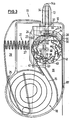
- the Fign. 1 to 3 show a schematic sectional view a first embodiment of the invention.
- the dispenser 11 is in its outer contour through the housing 12, the nose adapter 13 and the actuating means 20, a Operating lever, determined.
- the nose adapter 13 serves the nasal Drug application in the patient.
- the nose adapter 13th At his the housing 12 facing away from the front end, the nose adapter 13th a nozzle 14a for the exit of the medium to be discharged.
- Dispenser side opens the discharge channel 14 of the nose adapter 13th at the nozzle.
- Axially movable and guided accordingly is the Shock 30 arranged in the housing so that it with its nozzle-side End projects into the nose adapter 13.
- the thorn 30 is formed at its storage chamber side end so that it is suitable, the cover of the storage chamber 16 to pierce.
- the push pin 30, for example two orthogonal overlying, conical on the storage chamber 16 towards aligned cutting edges. These are firm and cutting enough to be preferred as Cover of the storage chamber used foil material made of For example, metal-steamed plastic film can, so severed that in the separation process no chip formation the film material occurs.
- the absence of chip formation is important in that chips could be to block the discharge channel 14 at least partially and thus the discharge of the predetermined amount of medium unintentionally could reduce, so that the predetermined, portioned Quantity of active ingredient can no longer be applied.
- the storage chamber reliably at the puncture site of Shock thorns are opened. It is particularly advantageous if the pierced material sealed to the in the storage chamber penetrated thrust pin abuts.
- the abutment pin 30 is still formed by the abutment ring 35, the one hand, the flush-mounted system to the Surface of the pierced lid of the storage chamber 16 on the other hand, in cooperation with the slide switch 33 for actuating the push pin, namely for pushing down the push pin 30 in the direction of the Transport drum 40 with the receptacle 41, in which a Storage chamber 16 of the blister strip 15 is used can.
- the shock pin in its unactuated rest position does not come into engagement with the blister strip 15 is on the one hand attached to the housing 12 and on the other hand in attached a correspondingly formed receptacle 37
- Leaf spring 36 is provided, which the thrust pin 30 in the direction of the nozzle 14a applied towards.
- the spring force is chosen so that the shock pin 30 unconfirmed safe in its rest position shown in Fig. 1 is held and that on the other hand via the slide 33rd applied operating forces do not go beyond an operable level.
- the in Figs. 1 to 3, not shown storage chambers of Blister strip 15 are from the recordings 41 of the transport drum 40 recorded and therein at least in the direction of rotation of the drum kept aligned.
- the blister strip 15 is preferably in Store a drum memory 18 stockpiled so that a larger Blister strip length and thus a larger number of storage chambers can be stored.
- the diameter of the drum memory 18, in particular, the inner diameter of the wound blister strip is limited by the material stiffness of the blister strip itself.
- the blister strip is from the stored material in the course the sequence of operations of the donor gradually unwound and first led to the transport drum 40, at least partially is wrapped by the blister strip 15.
- the wrap area the transport drum 40 through the blister strip 15 extends at least over the portion of the shock pin 30 opposite. In the wrapping area, it is advantageous if, at least in sections, conducting means 28 are provided, which the radial play of the blister strip 15 relative to the transport drum 40th limit.
- the Housing 12 through the export shaft 19 may be a tear-off edge 87 pre See sections of the protruding blister strip can be demolished and disposed of.
- the actuating means 20 provided by the action of the return spring 25 in his unconfirmed retirement position.
- the storage element 21 in the present case a spring accumulator, can be prestressed.
- the spring accumulator 21 is supported on the one hand on the actuating means 20 and on the other hand on a support plate 26 from.
- From the carrier plate 26 protrudes both the slide 33rd as well as the slider 44, on the driver 43 of the transport drum 40 acts, from.
- a stop pin 23 is formed, which with a on Actuator 20 provided stop member 24 cooperates, wherein the two elements for limiting the Relativweges serve each other.
- the transport drum 40 has 49 receptacles on its peripheral side 41 for storage body on. At least one of her End faces 42 has concentric with their housing fixed arranged pivot axis 52 arranged driver 43.
- the Driver 43 are as compared to the end face 42 cylindrical trained surveys. Everybody is recording 41 associated with a driver 43 for a storage chamber.
- the drivers 43 are arranged on material tongues 45, which are formed in the end face 42. It separates U-shaped slot 45a, the tongue of material 45 from the rest Surface of the front side 42.
- the drivers 43 are each arranged at the free end of the material tongues 45, at which this not connected to the front side 42. So that the transport drum 40 is secured against turning back, is the housing side a reverse rotation locking element 50 is formed, which with the drivers 43 cooperates.
- Position may preferably formed ramp-shaped Be reversed locking element over it, that the driver against the effect of material elasticity of the material tongue 45 in the plane of the end face 42 in the axial direction the axis of rotation 52 is pressed.
- a contact surface 51 formed in the essentially has the outer contour of a driver 43 and which limits the ramp of the reverse-rotation locking element. It is thus an edge formed on the ramp, behind the driver 43 due to the material elasticity of the material tongue in its original position springs back and then due to the Contact with the stop surface 51 is no longer able to to be turned in the opposite direction.
- the situation must be of the reverse rotation locking element 50 with respect to the position of the thrust pin 30th be arranged so that when a driver 43, the reverse rotation locking element just run over with its contact surface 51 has, a receptacle 41 for a storage body 16 is accurate in the position in which it is aligned with respect to the thrust pin 30 is.
- the reverse rotation locking element is accurate arranged diametrically opposite the thrust pin 30.
- Fig. 1 shows the dispenser 11 in its unactuated initial position. Will the donor now at his actuator 20 is actuated, then first the memory element 21, a spring accumulator, biased.
- the spring store 21 is here between the carrier plate 26 and the actuating means 20th arranged. In this case, the support plate 26 at this time still fixed by a latching with the housing 12 with respect to the housing 12 held. During this operation will be So only the spring 21 and the return spring 25th biased.
- Fig. 3 shows the position of the parts to each other at the end of a Austragvorganges before the actuating means 20 and the movable Parts of the dispenser 11 again in the illustrated in Fig. 1 Initial situation.
- the support plate 26 is moved together with the elements attached to it in the direction of the transport drum 40.
- the transport drum 40 is relatively movable, along the end face 42 of the transport drum 40 with their drivers 43. It is already in the in Figs. Characterized in that the driver 43 is in contact with the slider 44, a withdrawal of blister strip on the housing 12 is prevented by a rotation of the transport drum 40 is blocked in the conveying direction.
- the end face 56 of the slider 44 comes into contact with a driver 43.
- the driver 43 along which moves the lower longitudinal edge 55 of the slider 44, either in a recess of the Dump slider 44 or to get by appropriate design of the longitudinal edge 55 under the slider 44.
- the drum on the driver 43 which is in abutment with the end face 56 of the slider 44, so further rotated that the next recess 46 with the storage chamber 16 held therein of the blister strip 15 in position relative to the thrust pin 30 is located.
- the driver 43 has turned so far that its - seen in the direction of the push pin 30 - upper edge below the lower edge 55 of the slider 44 is located.
- the slide valve 33 Only when this position reaches the transport drum 40 is, the slide valve 33 comes with its control edge 34 in contact with the thrust pin and trained there Control edges, such as the 6.3ring 35.
- the training the control edge 34 of the slide valve 33 is such that the thrust pin 30 initially in the direction of the storage chamber 16, in the corresponding receptacle 41 of the transport drum 40 held aligned on the thrust pin 30 out and is moved against the action of the leaf spring 36. After that pierces the pushrod with its edges designed for this purpose the storage chamber 16 occlusive material in the Usually a foil material, usually with metal vapor or Coated similar.
- the push pin 30 as a slide of a Slide valve be designed so that with reaching the End position of the push pin, in which the tip of the push pin completely protruding into the storage chamber 16, the lid of the Memory chamber 16 is pierced, but still sealed annularly abuts the thrust pin 30, immersed.
- the valve opens when the push pin 30 has reached its end position.
- the fluid compressed in the pump chamber 22, namely, air through the flow channel 32 of the thrust pin 30th through escape into the storage chamber 16.
- Fluid with the medium in the storage chamber 16 for example, a liquid or a powder, mixed and passes through the first flow channel leading to the nozzle 14a leads, out.
- Fig. 4 shows an alternative embodiment of an inventive Donor.
- the actuating means 20 is provided. Rather, that must Actuator 20 by the user himself of the Fig. 3 corresponding end position in the Fig. 1 corresponding Actuating initial position to be transferred. Otherwise match the various elements of Fig. 4 the corresponding Elements in FIGS. 1 to 3 and are too - so far available - numbered the same.
- the push pin 30 has on an outer side a connection piece for the second flow channel, the fluidly connect the thrust pin to the pump chamber 22 can.
- the thrust pin 30 is about the leaf spring 36 in his Resting position held and can over the slide 33, the with the support plate 26 not shown in this illustration is brought into his discharge position.
- the control edge 34 comes in the course of an operation of the slide switch 33 in contact with the contact ring 35 am Impact spike.
- a blister strip 15 provided in the form of a drum memory 18, a blister strip 15 provided.
- the blister strip 15 has a plurality of storage chambers 16, each containing medium 17.
- the blister strip 15 is at least partially over the Transport drum 40 out.
- the transport drum 40 has Receivers 41 for the storage chambers 16 of the blister strip 15 on.
- the transport drum is on its peripheral side 49 provided with the recordings 41.
- the driver 43 which is fixed arranged on the front side, from this in axial Direction protruding surveys are formed.
- the slide 44 In the illustrated Actuation starting position is the slide 44, which is connected to the base plate 26, both as a reverse rotation lock as well as a lock that pulls out the Blister strip from the dispenser prevented, so a twist lock.
- the slider 44 is in the illustrated unactuated starting position with its front 56 in inci with a first driver 43.
- Towagen located the lower longitudinal edge 55 in abutment with a second Mit Economics 43.
- the plant between a driver 43 and the Front side 56 prevents turning back the transport drum 40.
- the second driver 43 acts due to its investment with the lower longitudinal edge 55 of the slider twisting the transport drum opposite. Therefore, by slider 44 and drum 40 a complete anti-rotation device for the transport drum 40 formed.
- the functional sequence for a dispenser as shown in Fig. 4 is, corresponds completely to the functional sequence a dispenser in the embodiment according to FIGS. 1 to 3. Therefore, in this regard, the corresponding description to the Fign. 1 to 3 referenced.
- the blister strip 15 is on the one hand by guide elements and on the other by the corresponding shaped recesses 46 on the peripheral side 49 of the Transport drum 40 held.
- the drivers 43 are formed, to which the Slider 44 can act.
- the slider 44 a Recess 46, in which a driver 43 can dip.
- the recess 46 is formed so that they themselves on the one hand along the lower longitudinal edge 55 of the slider 44th extends and on the other hand, the end face 42 of the transport drum 40 faces.
- the slider 44 is a linear, a Kreissehne the transport drum 40 following movement performs, the guide rails 58 are provided, in which he is led.
- the guide rails 58 are in the housing 12th formed of the dispenser 11.
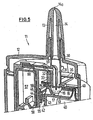
- the thrust pin 30 in the storage chamber 16 with the medium 17th immersed In the illustrated operating position of the dispenser 11 is the thrust pin 30 in the storage chamber 16 with the medium 17th immersed.
- the push pin has with its front edges the closure material, which hermetically shoots the storage chamber 16, pierced.
- the second flow channel to the Supply of fluid from the pump chamber 22 into the storage chamber 16 is, is via the connection point 59 with the fluid channel 60, from the storage chamber 22 to the junction 59th leads, has been connected.
- the memory element 21 for the implementation of a stroke of the pump piston 57 only then ensures when this fluidic connection via the connection point 59 is made, it is unnecessary, a switching valve in the fluid path between the pump chamber 22 and the second flow channel 32 to provide.
- the displaced from the pump chamber 22 fluid passes through the Flow channel 60 and the second flow channel 32 of the shock pin 30 in the storage chamber 16. There it is with the in the storage chamber 16 prepared medium 17 is mixed. This depends on the shape of the medium, whether pasty, liquid or firm, independent. Since the bumper 30 is almost sealing in the material, which has closed the storage chamber, concludes, remains as the only way out of the storage chamber 16 for the mixture of Medium 17 and supplied fluid alone, the first flow channel 31st The first flow channel 31 leads to the flow channel 14 in the nose adapter 13 and thus to the nozzle 14a. There, the discharge of fluid takes place and medium from the dispenser 11.
- FIG. 6 shows in a schematic representation, in the unactuated rest position, a detailed view of transport drum 40 and slider 44th
- drivers 43 are arranged, of Project material tongues 45 in the axial direction.
- the material tongues 45 formed by slots 45a, which in the end face 42 of Transport drum are introduced.
- the drivers 43 are concentric arranged to the axis of rotation 52 of the transport drum 40.
- the thrust pin 30 with the abutment ring 35.
- the shock pin 30 on the one hand in the nose adapter 13 guided and on the other hand of the leaf spring 36 in its unactuated Rest position held.
- the thrust pin 30 in the direction of the transport drum be moved as described above in the description of the operating sequences has been described.
- the slider 44 Upon actuation of the dispenser, the slider 44 is in the direction of the upper, first driver 43a moves. Once the slider 44 with its end face 56 comes into contact with the driver 43a leads the transport drum the further movement of the slider 44th a rotational movement about its axis of rotation 52.
- the next, second driver 43b in the recess 46, the on Slider 44 is formed in a region of the lower Longitudinal edge 55 of the slider 44 extends and the front side 42 of the transport drum 40 is aligned. there it is possible, the recess 46 with a stop surface 47th seen at its in the direction of movement of the slider 44, rear End.
- This stop surface 47 can in plant arrive with the second driver 43b and so on the one hand a transport function for the continuation of the rotational movement the transport drum 40 in the direction of actuation and also serve as reverse rotation lock during the operation of the dispenser.
- the stop surface 47 runs this as possible plane-parallel to the front side 56 of the slider 44, so that the second Mit supportive 43b is not able to the stop surface 47 to run over.
- the movement path of the transport drum and the slider 44 in the transport direction thereby limited that with respect to the first driver 43a next driver 43 c in abutment with the lower longitudinal edge 55 of the slider 44th arrives.
- the slider 44 without rotating the transport drum 40 can be moved back to its original position, it is advantageous, another, preferably on the transport drum 40 Provide over 43 driver acting backstop, as shown for example in FIGS. 1 to 3 described has been.
- the Stop surface 47 opposite side 48 of the recess 46 is also formed ramp-shaped.
- the slider 44 may be the opposite side 48 the driver 43b in the direction of the end face 42 of the Push in transport drum 40. This happens contrary the effect of the material tongue 45b of the driver 43b forces generated due to elastic deformation. Consequently For example, the slider 44 can move over the dog 43b during the backward movement glide away.
- Figures 7a-7c is a representation of an alternative Embodiment of a shock pin 30 shown, wherein in the Figures 7a and 7b, the positioning of the thrust pin 30 in the Nose adapter 13 and the formation of the connection point 59th the flow channel 60 is shown.
- the housing of the thrust pin comprises an annular Body and a connection point 59 to the annular body to fluidly connect with the pump chamber 22.
- By the Connection point then passes a fluid flow in the ring-shaped second flow channel 32 and flows radially seen on the outside of the storage chamber 16 of the blister strip 15, in the storage chamber. Since the Outer diameter of the thrust pin 30 to the inner diameter the storage chamber 16 of the blister strip is adapted a flow along the housing wall of the storage chamber 16 ensured.
- the push pin 30 has two right-angled and over-lying Cutting edges 62 on. The cutting edges can in particular have a substantially triangular cross-section and make sure that after cutting through the cover an insertion of the thrust pin into the storage chamber 16 is possible. It can over the as 6.3ring 35 trained side wall of the push pin 30 and the sealing Attachment of the shock pin secured to the outside of the storage chamber 16 become.
- the deflection effect is utilized, which arises when the incoming air in the lowest point of the container, inflowing from all sides, meets and then can escape only in the middle up. This ensures good discharge of the medium 17 to be discharged from the storage chamber 16.
- FIG. 7b the view of the impact mandrel 30 can be seen from below, in which the discharge channel 31 leads to the flow channel 14, which opens into the nozzle 14a.
- the shock pin 30 on its outside also still an overflow hole 61 fluidly connected to the atmosphere becomes.
- the overflow hole is fluidic with the second flow channel 32 connected, wherein a check valve ensures that no fluid escapes from the pump chamber 22 via the overflow hole 61.
- the Overflow hole 61 serves to allow the user to discharge can support it by actively sucking in air. So this active suction can be supported, it must be possible that the air flowing through the Studentsstömloch 61, the sucked Volume of the user substantially corresponds to the discharge process can participate. It can also be provided that the overflow hole 61 is connected to the first flow channel 31 and the additional intake due to the additional Venturi effect Air flow is achieved. Due to the high flow speed the volume flow passing through the overflow hole 61 becomes exhausted Medium or a Sucked out mixture of fluid and medium from the storage chamber 16.
- FIG 7c are partial view of the thrust pin in a perspective view 30 shown.
- the incoming air via the connection point 59 passes inside the housing of the thrust pin 30 to the ring portion 63, wherein between the sleeve 64 and the needle 65, which is the thrust pin forms with the cutting edges 62 and also a sleeve-shaped Body having the first flow channel 31 in its interior flows through.
- the second partial view of Figure 7c shows the needle 65, which is arranged inside the sleeve 64 and in which the first Flow channel 31 is formed, which serves the discharge of the medium.
- the cutting edges 62 for severing provided the cover of the reservoir.
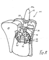
- FIG. 8 shows an alternative embodiment of a dispenser.
- the discharge of the medium takes place via the nozzle 14a in the nose adapter 13.
- the shock pin 30 Inside the case and fluidly connected with the flow channel 14 of the nose adapter 13 is the shock pin 30.
- Der Shock pin 30 has on its outside a connection point 59th on, via which the thrust pin fluidly connected to the pump chamber 22 is. In this case, the shock pin 30 via the leaf spring 36 in its rest position held.
- Inside the housing 12 of the dispenser 11 are for Guide the linear motion guide cam 66 is formed. About one not shown switching means, such as a slide switch, can the shock pin 30 from the rest position in the illustrated operating end position be spent.
- the blister strip 15 which has a plurality of storage chambers 16, provided.
- the blister strip 15 is at least partially guided over the transport drum 40, the Receivers 41 for each one storage chamber 16 of the Blister strip 15 has.
- the transport drum is for this purpose provided on its peripheral side 49 with the receptacles 41.
- the transport drum 40 driver 43rd on, as elevations projecting in the axial direction are formed.
- the hook claw 66 engages behind one Moving out of the actuating means 20 one of the drivers 43 and twists the transport drum 40 at this Clamping movement to exactly one storage chamber 16, or to exactly a recording 41.
- the functional sequence for operating a dispenser according to FIG. 8 corresponds completely to the functional sequence a dispenser according to the figures 1 to 3, including in this regard is referred to the corresponding description.
- donor media of many training be discharged from a donor. It is possible, both powdered and liquid or pasty media unsubscribe. As a rule, it is considered fluid that comes out of the pump chamber 22 is displaced and that for the discharge of the medium out of the storage chamber, using ambient air. It but other fluids can be used. Further became the invention based on the application in a donor for the explained nasal area. Instead of the nose adapter 13 can but other applicators also occur. An example for another applicator would be a throat adapter. Thus, can the dispenser of the invention in a variety of applications be used. This is especially true of media the case, the pharmaceutical agents, for example Pain or migraine or other, especially nasal contains medication to be administered. The use of the However, donors is not on the pharmaceutical field or medical use.
Description
- Fign. 1 bis 3
- eine schematische Schnittdarstellung einer ersten Ausführungsform der Erfindung;
- Fig. 4
- die schematische Darstellung einer zweiten Ausführungsform in teilgeschnittener Darstellung;
- Fig. 5
- eine schematische Querschnittdarstellung eines erfindungsgemäßen Spenders im Bereich des Austragkanals und der Speicherkammer, aus der gerade Medium ausgetragen wird;
- Fig. 6
- eine vergrößerte schematische Querschnittsdarstellung des Schiebers der Transporttrommel;
- Fign. 7a bis 7c
- eine alternative Ausgestaltung von Nasenadapter und Stoßdorn; und
- Fig. 8
- eine teilgeschnittene Darstellung einer weiteren Ausführungsform
Im weiteren Verlauf der Translationsbewegung der Trägerplatte 26 gelangt die Stirnseite 56 des Schiebers 44 in Anlage mit einem Mitnehmer 43. Ab diesem Moment ist es dem Mitnehmer 43, entlang dessen sich die untere Längskante 55 des Schiebers 44 bewegt, möglich, entweder in eine Ausnehmung des Schiebers 44 einzutauchen oder aber durch entsprechende Gestaltung der Längskante 55 unter den Schieber 44 zu gelangen. Von dem Schieber 44 angetrieben wird die Trommel über den Mitnehmer 43, der sich in Anlage mit der Stirnseite 56 des Schiebers 44 befindet, so weitergedreht, daß sich die nächste Ausnehmung 46 mit der darin gehaltenen Speicherkammer 16 des Blisterstreifens 15 in ihrer Position gegenüber dem Stoßdorn 30 befindet. Zu diesem Zeitpunkt hat sich der Mitnehmer 43 so weit weitergedreht, daß seine - in Richtung auf den Stoßdorn 30 gesehen - obere Kante unterhalb der Unterkante 55 des Schiebers 44 befindet. Dieser kann somit an dem Mitnehmer 43 vorbeigleiten, wobei ein Rückdreh-Sperreffekt dadurch entsteht, daß sich dieser Mitnehmer 43 weiterhin in Anlage mit der unteren Längskante 55 des Schiebers 44 befindet. Gleichzeitig gelangt der entgegen der Drehrichtung der Transporttrommel gesehen übernächste Mitnehmer 43 ebenfalls in Anlage an die untere Längskante 55 des Schiebers 44. Dadurch wird ein Weiterdrehen (Verdrehen) der Trommel verhindert. Nachdem sowohl ein Verdrehen in Transportrichtung der Trommel als auch in Gegenrichtung verhindert wird, ist somit eine lagesichere Ausrichtung einer Aufnahme 41 ausgebildet. Die Ausnehmung 46 und die darin gehaltene Speicherkammer 16 befindet sich in fixierter, zum Stoßdorn 30 hin ausgerichteter Lage.
In der Figur 7b ist die Ansicht des Stoßdorns 30 von unten zu sehen, bei dem der Austragkanal 31 zum Strömungskanal 14 führt, der in der Düse 14a mündet.
Claims (20)
- Spender für in Speicherkammern (16) eines Speicherkörpers portioniert verpackte, vorzugsweise wenigstens einen pharmazeutischen Wirkstoff enthaltende austragbare Medien (17), mit einem Stoßdorn (30), der in Speicherkammern (16) einführbar ist, einer Fluidpumpe mit einer Pumpenkammer (22), aus der das Fluid der Speicherkammer zum Austragen des Mediums zuführbar ist, und mit einem Betätigungsmittel (20), durch dessen Betätigung sowohl die Positionierung einer Speicherkammer (16) in Bezug auf den Stoßdorn (30) als auch das Austragen des Mediums (17) erfolgt, gekennzeichnet, durch ein Speicherelement (21), das während eines ersten Betätigungsabschnittes verspannbar ist und zu seiner Entspannung während eines zweiten Betätigungsabschnittes durch Lösen einer Verrastung (27) auslösbar ist und dabei in Folge:die Positionierung der Speicherkammer (16) in Bezug auf den Stoßdorn (30),die Öffnung der Speicherkammer (16) duch den Stoßdorn (30) mit Schaffung einer Fluidverbindung zwischen Pumpenkammer und Speicherkammer unddie Zuführung des Fluids zur Speicherkammer (16) zum Austrag des Mediums bewirkt.
- Spender nach Anspruch 1, dadurch gekennzeichnet, dass das Speicherelement (21) erst dann für einen Hub des in die Pumpenkammer (22) eingreifenden Pumpenkolbens (57) sorgt, wenn die Fluidverbindung hergestellt ist.
- Spender nach Anspruch 1, dadurch gekennzeichnet, daß das Speicherelement (21) eine Pumpenkammer ist, wobei während des ersten Betätigungsabschnittes in der Pumpenkammer ein Druck aufgebaut wird, wobei die Pumpenkammer durch ein schaltbares Ventil verschlossen und beim Übergang vom ersten zu dem zweiten Betätigungsabschnitt das Ventil abhängig vom Betätigungsweg des Betätigungsmittels (20) im Öffnungssinne betätigt wird.
- Spender nach einem der vorhergehenden Ansprüche, dadurch gekennzeichnet, daß das austragende Medium durch Ausblasen des in der Pumpenkammer (22) enthaltenen Fluids erfolgt.
- Spender nach einem der vorhergehenden Ansprüche, dadurch gekennzeichnet, daß am Stoßdorn (30) wenigstens ein erster Strömungskanal (31) zum Austrag des Mediums (17) aus dem Speicherkörper (16) und ein zweiter Strömungskanal (32) zur Zufuhr des Fluids aus der Pumpenkammer (22) in die Speicherkammer (16) ausgebildet ist.
- Spender nach Anspruch 5, dadurch gekennzeichnet, daß der Stoßdorn (30) als Schaltelement des die Pumpenkammer (22) abschließende Ventils ausgebildet ist.
- Spender nach Anspruch 6, dadurch gekennzeichnet daß der zweite Strömungskanal (32) ringförmig ausgebildet ist und den ersten Strömungskanal (31) umgibt.
- Spender nach einem der vorhergehenden Ansprüche, dadurch gekennzeichnet, daß die Speicherkammer (16) durch ein Folienmaterial verschlossen ist und der Stoßdorn (30) derart ausgebildet ist, daß der Rand des Stoßdorns (30) dichtend an dem von ihm durchstoßenen Folienmaterial anliegt.
- Spender nach einem der vorhergehenden Ansprüche, dadurch gekennzeichnet, daß der Spender (11) eine Transporttrommel (40) zum Transportieren und Ausrichten der Speicherkammern (16) aufweist, wobei die Transporttrommel (40) an ihrer Umfangsfläche (49) Aufnahmen (41) für jeweils eine Speicherkammer (16) aufweist.
- Spender nach Anspruch 9, dadurch gekennzeichnet, daß eine auf die Transporttrommel (40) einwirkende Verdrehsperre vorgesehen ist, wobei durch die Wirkung der Verdrehsperre eine Aufnahme (41) für eine Speicherkammer (16) in ihrer bzgl. dem Stoßdorn (30) ausgerichteten Lage gehalten ist.
- Spender nach Anspruch 9 oder 10, dadurch gekennzeichnet, daß eine auf die Transporttrommel (40) einwirkende Rückdrehsperre ausgebildet ist, die eine Drehbewegung der Transporttrommel (40) in einer Transportrichtung erlaubt und eine Drehbewegung entgegen der Transportrichtung sperrt, wobei die Rückdrehsperre vorzugsweise in eine leere Aufnahme (41) eingreift.
- Spender nach einem der Ansprüche 9 bis 11, dadurch gekennzeichnet, daß die Transporttrommel(40) an einer Stirnseite (42) Mitnehmer (43, 43a, 43b, 43c) aufweist, wobei vorzugsweise jeder Aufnahme (41) der Umfangsfläche (49) stirnseitig ein Mitnehmer (43) zugeordnet ist.
- Spender nach Anspruch 12, dadurch gekennzeichnet, daß das Betätigungsmittel (20) wenigstens einen auf Mitnehmer (43) einwirkenden Schieber (44) aufweist, wobei der Schieber (44) zugleich zumindest entweder als Verdrehsperre oder als Rückdrehsperre ausgebildet ist.
- Spender nach Anspruch 13, dadurch gekennzeichnet, daß der Schieber (44) mittels dem Betätigungsmittel (20) verschiebbar und so geführt angeordnet ist, daß er auf einer Kreissehne entlang der Stirnseite (42) an der Transporttrommel 40) vorbeibewegt wird.
- Spender nach einem der Ansprüche 12 bis 14, dadurch gekennzeichnet, daß die Mitnehmer (43) als in axialer Richtung von der Stirnseite (42) abragende, vorzugsweise zylindrisch ausgebildete, Erhebungen ausgebildet sind, die konzentrisch zur Drehachse (52) der Transporttrommel angeordnet sind
- Spender nach Anspruch 15, dadurch gekennzeichnet, daß die Mitnehmer (43) auf in der Stirnseite (42) ausgebildeten Materialzungen (45) angeordnet sind, wobei die Materialzungen (45) vorzugsweise U-förmig ausgebildet sind, in Drehrichtung der Transporttrommel der Stirnseite (42) der Transporttrommel über einen Materialsteg verbunden sind und derart ausgebildet sind, daß sie um die Höhe der jeweiligen Erhebung entgegen der dabei entstehenden Biegekräfte in Richtung auf das Innere der Transporttrommel (40) verbringbar sind.
- Spender nach einem der Ansprüche 12, 15 oder 16, dadurch gekennzeichnet, daß das Betätigungsmittel (20) eine Hakenkralle (66) aufweist, wobei die Hakenkralle (66) zum Transportieren der Transporttrommel (40) mit wenigstens einem Mitnehmer (43) in Eingriff gelangt und bei der Rückbewegung axial versetzt an wenigstens einem Mitnehmer (43) vorbei zurückgeführt wird.
- Spender nach einem der Ansprüche 14 bis 16, dadurch gekennzeichnet, daß der Schieber (44) im wesentlichen balkenförmig ausgebildet ist, wobei sich seine Längskante (55) in Richtung der Kreissehne entlang derer der Schieber bzgl. der Transporttrommel (40) beweglich ist, erstreckt, wobei seine Stirnseite (56) auf einen Mitnehmer (43, 43a) hin ausgerichtet ist, wobei der Schieber (44) während eines Betätigungsvorganges mit seiner Stirnseite (56) in Anlage mit einem Mitnehmer (43, 43a) gelangt; daß der Schieber (44) eine Ausnehmung (46) ausweist, die auf seiner der Stirnseite der Transport-trommel (40) zugewandten Seite ausgebildet ist und die sich auch in den Bereich der den Mitnehmern (43) zuge-wandten Längskante (55) erstreckt, wobei die Ausnehmung (46) der Aufnahme von dem Mitnehmer (43, 43b) dient, der auf den Mitnehmer (43, 43a) folgt, welcher bei einer Betätigung mit der Stirnseite (56) des Schiebers (44) in Anlage gelangt; daß die in Bewegungsrichtung hintere, parallel zur Stirnseite (56) des Schiebers (44) ausgerichtete, die Ausnehmung (46) begrenzende Anschlagfläche (47) in ihrer Lage bzgl. der Stirnseite (56) und den Mitnehmern (43) derart ausgerichtet ist, daß eine in Transportrichtung der Transporttrommel (40) gerichtete kraftschlüssige Verbindung zwischen einem in der Aufnahme befindlichen Mitnehmer (43, 43b) und Anschlagfläche (47) herstellbar ist und daß die Ausnehmung (46) an der in Bewegungsrichtung vorderen, der Anschlagfläche (47) gegenüberliegenden Seite (48), die die Ausnehmung begrenzt, rampenförmig ausgebildet ist.
- Spender nach einem der Ansprüche 9 bis 18, dadurch gekennzeichnet, daß eine auf die Transporttrommel (40) einwirkende, vorzugsweise dem Schieber (44) diametral gegenüberliegende Rückdrehsperre vorgesehen ist, deren Sperrwirkung durch Kraftschluß zwischen einem transporttrommelseitigen Mitnehmer (43) und einer gehäusefesten Anlagefläche (51) erreicht wird, wobei die Anlagefläche (51) in Transportrichtung der Transporttrommel (40) überfahrbar ist.
- Spender nach einem der vorhergehenden Ansprüche, dadurch gekennzeichnet, daß der Speicher (15) ein Blisterstreifen ist, der eine Mehrzahl von Speicherkammern (16) mit austragbarem Medium (17) aufweist, wobei der Blisterstreifen in einem Trommelspeicher (18) bereitgestellt ist.
Applications Claiming Priority (2)
| Application Number | Priority Date | Filing Date | Title |
|---|---|---|---|
| DE10011120A DE10011120A1 (de) | 2000-03-09 | 2000-03-09 | Spender für Medien |
| DE10011120 | 2000-03-09 |
Publications (3)
| Publication Number | Publication Date |
|---|---|
| EP1132104A2 EP1132104A2 (de) | 2001-09-12 |
| EP1132104A3 EP1132104A3 (de) | 2002-03-20 |
| EP1132104B1 true EP1132104B1 (de) | 2005-11-16 |
Family
ID=7633859
Family Applications (1)
| Application Number | Title | Priority Date | Filing Date |
|---|---|---|---|
| EP01105838A Expired - Lifetime EP1132104B1 (de) | 2000-03-09 | 2001-03-09 | Spender für Medien |
Country Status (4)
| Country | Link |
|---|---|
| US (1) | US6725857B2 (de) |
| EP (1) | EP1132104B1 (de) |
| AT (1) | ATE309833T1 (de) |
| DE (2) | DE10011120A1 (de) |
Cited By (1)
| Publication number | Priority date | Publication date | Assignee | Title |
|---|---|---|---|---|
| EP2228086A1 (de) | 2006-05-18 | 2010-09-15 | Boehringer Ingelheim International GmbH | Zerstäuber |
Families Citing this family (46)
| Publication number | Priority date | Publication date | Assignee | Title |
|---|---|---|---|---|
| US7080644B2 (en) * | 2000-06-28 | 2006-07-25 | Microdose Technologies, Inc. | Packaging and delivery of pharmaceuticals and drugs |
| GB0209528D0 (en) * | 2002-04-26 | 2002-06-05 | Glaxo Group Ltd | Medicament dispenser |
| GB0221493D0 (en) * | 2002-09-17 | 2002-10-23 | Glaxo Group Ltd | Method for loading a medicament dispenser with a medicament carrier |
| US7395821B2 (en) | 2003-07-09 | 2008-07-08 | Cipla Limited | Multi-dose inhaler |
| GB2407042B (en) * | 2003-10-17 | 2007-10-24 | Vectura Ltd | Inhaler |
| NZ549588A (en) | 2004-02-24 | 2009-03-31 | Microdose Technologies Inc | Directional flow sensor inhaler |
| FR2881119B1 (fr) * | 2005-01-25 | 2010-07-30 | Valois Sas | Dispositif de distribution de produit fluide. |
| FR2881117B1 (fr) * | 2005-01-25 | 2010-07-30 | Valois Sas | Dispositif de distribution de produit fluide. |
| GB0507711D0 (en) * | 2005-04-15 | 2005-05-25 | Vectura Group Plc | Improved blister piercing |
| US8763605B2 (en) | 2005-07-20 | 2014-07-01 | Manta Devices, Llc | Inhalation device |
| AU2007210177C1 (en) * | 2006-01-31 | 2012-11-01 | Oriel Therapeutics, Inc. | Dry powder inhalers having spiral travel paths, unit dose microcartridges with dry powder, related devices and methods |
| FR2904229B1 (fr) * | 2006-07-25 | 2008-10-10 | Valois Sas | Dispositif de distribution de produit fluide. |
| US7699191B2 (en) * | 2006-11-09 | 2010-04-20 | Ethicon Endo-Surgery, Inc. | Surgical multiple use adhesive applier |
| WO2008086413A2 (en) | 2007-01-09 | 2008-07-17 | Mystic Pharmaceuticals, Inc. | Intranasal cartridge devices |
| US9248076B2 (en) | 2007-05-16 | 2016-02-02 | Mystic Pharmaceuticals, Inc. | Dose dispensing containers |
| CN105776119B (zh) | 2007-05-16 | 2019-04-23 | 神秘制药公司 | 组成物单位剂量分配容器 |
| US8683995B2 (en) | 2007-05-16 | 2014-04-01 | Mystic Pharmaceuticals, Inc. | Dose dispensing containers |
| US8415390B2 (en) | 2008-05-30 | 2013-04-09 | Microdose Therapeutx, Inc. | Methods and compositions for administration of oxybutynin |
| US9119777B2 (en) | 2008-05-30 | 2015-09-01 | Microdose Therapeutx, Inc. | Methods and compositions for administration of oxybutynin |
| EP2170444B1 (de) * | 2007-07-06 | 2016-09-07 | Manta Devices, LLC | Inhalationsvorrichtungen zur lagerung und abgabe von medikamenten |
| US20100252032A1 (en) * | 2007-07-06 | 2010-10-07 | Boehringer Ingelheim International Gmbh | Inhaler |
| EP2011538B1 (de) * | 2007-07-06 | 2016-02-17 | Vectura Delivery Devices Limited | Inhalator |
| US11224704B2 (en) | 2007-07-06 | 2022-01-18 | Manta Devices, Llc | Dose delivery device for inhalation |
| CA2886525A1 (en) | 2007-09-14 | 2009-03-19 | Mystic Pharmaceuticals, Inc. | Deep draw container forming method |
| US8439033B2 (en) * | 2007-10-09 | 2013-05-14 | Microdose Therapeutx, Inc. | Inhalation device |
| EP2082767A1 (de) * | 2008-01-24 | 2009-07-29 | Vectura Delivery Devices Limited | Inhalator |
| US8371294B2 (en) * | 2008-02-29 | 2013-02-12 | Microdose Therapeutx, Inc. | Method and apparatus for driving a transducer of an inhalation device |
| FR2930163B1 (fr) * | 2008-04-16 | 2010-05-21 | Valois Sas | Dispositif de distribution de produit fluide. |
| PT2239001E (pt) * | 2009-03-30 | 2012-05-28 | Sanovel Ilac Sanayi Ve Ticaret As | Dispositivo inalador de pó seco |
| US8985101B2 (en) | 2009-05-21 | 2015-03-24 | Microdose Therapeutx, Inc. | Method and device for clamping a blister within a dry powder inhaler |
| US8763606B2 (en) * | 2009-05-21 | 2014-07-01 | Microdose Therapeutx, Inc. | Rotary cassette system for dry powder inhaler |
| US20110000481A1 (en) * | 2009-07-01 | 2011-01-06 | Anand Gumaste | Nebulizer for infants and respiratory compromised patients |
| TWI589313B (zh) * | 2010-01-05 | 2017-07-01 | 麥可朵斯斯若波特公司 | 醫藥遞送封裝及吸入器 |
| JP5995339B2 (ja) | 2012-05-25 | 2016-09-21 | アーヴェン イラチュ サナイ ヴェ ティヂャレット エー. エス.Arven Ilac Sanayi Ve Ticaret A.S. | 吸入装置のトリガー機構 |
| WO2013176639A1 (en) * | 2012-05-25 | 2013-11-28 | Sanovel Ilac Sanayi Ve Ticaret Anonim Sirketi | Inhaler device with an improved blister advancement mechanism |
| WO2013176640A1 (en) * | 2012-05-25 | 2013-11-28 | Sanovel Ilac Sanayi Ve Ticaret Anonim Sirketi | An inhaler comprising a inner body having an air channel |
| BR112014029334B1 (pt) * | 2012-05-25 | 2021-06-29 | Arven Ilac Sanayi Ve Ticaret A.S. | Dispositivo de inalação de pó seco com placa acionadora |
| FR2991184B1 (fr) * | 2012-05-31 | 2014-07-04 | Valois Sas | Dispositif de distribution de produit fluide. |
| FR2991185B1 (fr) * | 2012-05-31 | 2015-06-26 | Valois Sas | Dispositif de distribution de produit fluide. |
| GB201301192D0 (en) | 2013-01-23 | 2013-03-06 | Vectura Delivery Devices Ltd | A blister piercing element for a dry powder inhaler |
| RU2016116980A (ru) * | 2013-10-01 | 2017-11-13 | Новартис Аг | Ингаляционное устройство с направляющей блистеров, имеющее отдельную концевую дорожку, а также способы его применения |
| US11147936B2 (en) | 2014-05-02 | 2021-10-19 | Manta Devices, Llc | Dose delivery device with cover connected to dose chamber seal |
| DE102016115568A1 (de) * | 2016-05-04 | 2017-11-09 | Alfred Von Schuckmann | Vorrichtung zur Ausgabe einer durch Luft austragbaren Substanz |
| WO2018071427A1 (en) | 2016-10-11 | 2018-04-19 | Microdose Therapeutx, Inc. | Inhaler and methods of use thereof |
| WO2020198536A1 (en) * | 2019-03-27 | 2020-10-01 | Zeteo Biomedical, Llc | Hand operated devices for administration of a medicament |
| US11617716B2 (en) | 2021-06-10 | 2023-04-04 | Belhaven BioPharma Inc. | Dry powder formulations of epinephrine and associated methods |
Family Cites Families (9)
| Publication number | Priority date | Publication date | Assignee | Title |
|---|---|---|---|---|
| DK544589D0 (da) | 1989-11-01 | 1989-11-01 | Novo Nordisk As | Manuel betjent apparat til dispensering af en forudbestemt maengde af et pulverformet stof |
| GB9004781D0 (en) | 1990-03-02 | 1990-04-25 | Glaxo Group Ltd | Device |
| DE4021263C2 (de) * | 1990-07-04 | 1996-04-11 | Pfeiffer Erich Gmbh & Co Kg | Austragvorrichtung für Medien |
| DE4412041A1 (de) * | 1994-04-08 | 1995-10-12 | Pfeiffer Erich Gmbh & Co Kg | Austragvorrichtung für fließfähige Medien, insbesondere für den Austrag in nur einem Hub |
| ES2302332T3 (es) * | 1994-09-21 | 2008-07-01 | Nektar Therapeutics | Aparato y metodos para dispersar medicamentos en polvo seco. |
| DE19647947A1 (de) * | 1996-11-20 | 1998-05-28 | Pfeiffer Erich Gmbh & Co Kg | Austragvorrichtung für Medien |
| DE19704849B4 (de) * | 1997-02-08 | 2011-02-17 | Ing. Erich Pfeiffer Gmbh | Austragvorrichtung für Medien |
| US5855564A (en) * | 1997-08-20 | 1999-01-05 | Aradigm Corporation | Aerosol extrusion mechanism |
| DE19817417A1 (de) | 1998-04-18 | 1999-10-21 | Pfeiffer Erich Gmbh & Co Kg | Spender für Medien, insbesondere Pulver |
-
2000
- 2000-03-09 DE DE10011120A patent/DE10011120A1/de not_active Withdrawn
-
2001
- 2001-03-09 EP EP01105838A patent/EP1132104B1/de not_active Expired - Lifetime
- 2001-03-09 US US09/803,633 patent/US6725857B2/en not_active Expired - Lifetime
- 2001-03-09 AT AT01105838T patent/ATE309833T1/de not_active IP Right Cessation
- 2001-03-09 DE DE50108045T patent/DE50108045D1/de not_active Expired - Lifetime
Cited By (2)
| Publication number | Priority date | Publication date | Assignee | Title |
|---|---|---|---|---|
| EP2228086A1 (de) | 2006-05-18 | 2010-09-15 | Boehringer Ingelheim International GmbH | Zerstäuber |
| DE202007019531U1 (de) | 2006-05-18 | 2013-05-06 | Boehringer Ingelheim International Gmbh | Zerstäuber |
Also Published As
| Publication number | Publication date |
|---|---|
| EP1132104A2 (de) | 2001-09-12 |
| DE50108045D1 (de) | 2005-12-22 |
| EP1132104A3 (de) | 2002-03-20 |
| US6725857B2 (en) | 2004-04-27 |
| ATE309833T1 (de) | 2005-12-15 |
| DE10011120A1 (de) | 2001-09-13 |
| US20020032409A1 (en) | 2002-03-14 |
Similar Documents
| Publication | Publication Date | Title |
|---|---|---|
| EP1132104B1 (de) | Spender für Medien | |
| EP2396237B1 (de) | Austragvorrichtung mit tube | |
| DE60115931T2 (de) | Automatische injektionsvorrichtung mit nass- und trockenkammer | |
| EP1919542B1 (de) | Inhalationstherapievorrichtung mit einer ampulle für die bevorratung eines zu vernebelnden medikaments | |
| EP1084763B1 (de) | Spender zum ggf. zerstäubten Ausbringen eines insbesondere flüssigen Mediums aus einem Behältnis | |
| DE60210735T2 (de) | Transfervorrichtung sowie System mit einer Kappenanordnung, einem Behälter und der Transfervorrichtung | |
| EP1084765B1 (de) | Vorrichtung zum ggf. zerstäubten Ausbringen eines insbesondere flüssigen Mediums | |
| EP0957962B1 (de) | Spender für medien | |
| EP2144649B1 (de) | Verabreichungsvorrichtung mit funktionalem antriebsglied | |
| DE69434207T2 (de) | Gerät zum aufbringen mehrerer medikamente ins auge, ohne vorherige mischung im gerät | |
| DE60115480T2 (de) | Inhalationsgerät | |
| EP2252351B1 (de) | Verabreichungsvorrichtung mit halteeinrichtung | |
| WO2018096149A1 (de) | Vorrichtung zur abgabe einer substanz | |
| EP1667754A1 (de) | Verabreichungsvorrichtung mit einstech- und ausschütteinrichtung | |
| DE69630545T2 (de) | Verriegelbarer Handspender und Mischplatte zum Spenden von kleinen Materialmengen | |
| DD245817A5 (de) | Automatische injektionsvorrichtung | |
| DE19749514A1 (de) | Verfahren zum Ausbringen von wenigstens zwei verschiedenen Medien und Spender dafür | |
| EP2067718A1 (de) | Tablettendispenser | |
| DE10323603A1 (de) | Dosiervorrichtung mit einer Pumpeinrichtung | |
| EP0787655A1 (de) | Vorrichtung zum Entleeren eines Schlauchbeutels | |
| DE10036594A1 (de) | Austragvorrichtung für Medien | |
| EP2085147A1 (de) | Vorrichtung mit Druck beaufschlagtem Kolben zum Austragen einer Mehrfachspritze oder Mehrfachkartusche | |
| WO2019219130A1 (de) | Applikator | |
| DE69907039T2 (de) | Biegsamer antriebsmechanismus sowie abgabevorrichtung enthaltend einen solchen mechanismus | |
| DE10218782A1 (de) | Dosiervorrichtung mit wenigstens zwei Medienräumen |
Legal Events
| Date | Code | Title | Description |
|---|---|---|---|
| PUAI | Public reference made under article 153(3) epc to a published international application that has entered the european phase |
Free format text: ORIGINAL CODE: 0009012 |
|
| AK | Designated contracting states |
Kind code of ref document: A2 Designated state(s): AT BE CH CY DE DK ES FI FR GB GR IE IT LI LU MC NL PT SE TR |
|
| AX | Request for extension of the european patent |
Free format text: AL;LT;LV;MK;RO;SI |
|
| RIN1 | Information on inventor provided before grant (corrected) |
Inventor name: RITSCHE, STEFAN |
|
| PUAL | Search report despatched |
Free format text: ORIGINAL CODE: 0009013 |
|
| AK | Designated contracting states |
Kind code of ref document: A3 Designated state(s): AT BE CH CY DE DK ES FI FR GB GR IE IT LI LU MC NL PT SE TR |
|
| AX | Request for extension of the european patent |
Free format text: AL;LT;LV;MK;RO;SI |
|
| 17P | Request for examination filed |
Effective date: 20020824 |
|
| AKX | Designation fees paid |
Free format text: AT BE CH CY DE DK ES FI FR GB GR IE IT LI LU MC NL PT SE TR |
|
| 17Q | First examination report despatched |
Effective date: 20040413 |
|
| GRAP | Despatch of communication of intention to grant a patent |
Free format text: ORIGINAL CODE: EPIDOSNIGR1 |
|
| RAP1 | Party data changed (applicant data changed or rights of an application transferred) |
Owner name: ING. ERICH PFEIFFER GMBH |
|
| GRAS | Grant fee paid |
Free format text: ORIGINAL CODE: EPIDOSNIGR3 |
|
| GRAL | Information related to payment of fee for publishing/printing deleted |
Free format text: ORIGINAL CODE: EPIDOSDIGR3 |
|
| GRAS | Grant fee paid |
Free format text: ORIGINAL CODE: EPIDOSNIGR3 |
|
| GRAA | (expected) grant |
Free format text: ORIGINAL CODE: 0009210 |
|
| AK | Designated contracting states |
Kind code of ref document: B1 Designated state(s): AT BE CH CY DE DK ES FI FR GB GR IE IT LI LU MC NL PT SE TR |
|
| PG25 | Lapsed in a contracting state [announced via postgrant information from national office to epo] |
Ref country code: IE Free format text: LAPSE BECAUSE OF FAILURE TO SUBMIT A TRANSLATION OF THE DESCRIPTION OR TO PAY THE FEE WITHIN THE PRESCRIBED TIME-LIMIT Effective date: 20051116 Ref country code: FI Free format text: LAPSE BECAUSE OF FAILURE TO SUBMIT A TRANSLATION OF THE DESCRIPTION OR TO PAY THE FEE WITHIN THE PRESCRIBED TIME-LIMIT Effective date: 20051116 |
|
| REG | Reference to a national code |
Ref country code: GB Ref legal event code: FG4D Free format text: NOT ENGLISH |
|
| REG | Reference to a national code |
Ref country code: CH Ref legal event code: EP |
|
| GBT | Gb: translation of ep patent filed (gb section 77(6)(a)/1977) | ||
| REG | Reference to a national code |
Ref country code: IE Ref legal event code: FG4D Free format text: LANGUAGE OF EP DOCUMENT: GERMAN |
|
| REG | Reference to a national code |
Ref country code: CH Ref legal event code: NV Representative=s name: ZIMMERLI, WAGNER & PARTNER AG |
|
| REF | Corresponds to: |
Ref document number: 50108045 Country of ref document: DE Date of ref document: 20051222 Kind code of ref document: P |
|
| REG | Reference to a national code |
Ref country code: SE Ref legal event code: TRGR |
|
| PG25 | Lapsed in a contracting state [announced via postgrant information from national office to epo] |
Ref country code: DK Free format text: LAPSE BECAUSE OF FAILURE TO SUBMIT A TRANSLATION OF THE DESCRIPTION OR TO PAY THE FEE WITHIN THE PRESCRIBED TIME-LIMIT Effective date: 20060216 Ref country code: GR Free format text: LAPSE BECAUSE OF FAILURE TO SUBMIT A TRANSLATION OF THE DESCRIPTION OR TO PAY THE FEE WITHIN THE PRESCRIBED TIME-LIMIT Effective date: 20060216 |
|
| PG25 | Lapsed in a contracting state [announced via postgrant information from national office to epo] |
Ref country code: ES Free format text: LAPSE BECAUSE OF FAILURE TO SUBMIT A TRANSLATION OF THE DESCRIPTION OR TO PAY THE FEE WITHIN THE PRESCRIBED TIME-LIMIT Effective date: 20060227 |
|
| PG25 | Lapsed in a contracting state [announced via postgrant information from national office to epo] |
Ref country code: AT Free format text: LAPSE BECAUSE OF NON-PAYMENT OF DUE FEES Effective date: 20060309 |
|
| PG25 | Lapsed in a contracting state [announced via postgrant information from national office to epo] |
Ref country code: MC Free format text: LAPSE BECAUSE OF NON-PAYMENT OF DUE FEES Effective date: 20060331 Ref country code: LU Free format text: LAPSE BECAUSE OF NON-PAYMENT OF DUE FEES Effective date: 20060331 Ref country code: BE Free format text: LAPSE BECAUSE OF NON-PAYMENT OF DUE FEES Effective date: 20060331 |
|
| PG25 | Lapsed in a contracting state [announced via postgrant information from national office to epo] |
Ref country code: PT Free format text: LAPSE BECAUSE OF FAILURE TO SUBMIT A TRANSLATION OF THE DESCRIPTION OR TO PAY THE FEE WITHIN THE PRESCRIBED TIME-LIMIT Effective date: 20060417 |
|
| REG | Reference to a national code |
Ref country code: IE Ref legal event code: FD4D |
|
| ET | Fr: translation filed | ||
| PLBE | No opposition filed within time limit |
Free format text: ORIGINAL CODE: 0009261 |
|
| STAA | Information on the status of an ep patent application or granted ep patent |
Free format text: STATUS: NO OPPOSITION FILED WITHIN TIME LIMIT |
|
| 26N | No opposition filed |
Effective date: 20060817 |
|
| PGFP | Annual fee paid to national office [announced via postgrant information from national office to epo] |
Ref country code: NL Payment date: 20070319 Year of fee payment: 7 |
|
| PGFP | Annual fee paid to national office [announced via postgrant information from national office to epo] |
Ref country code: SE Payment date: 20070326 Year of fee payment: 7 |
|
| BERE | Be: lapsed |
Owner name: ING. ERICH PFEIFFER G.M.B.H. Effective date: 20060331 |
|
| PG25 | Lapsed in a contracting state [announced via postgrant information from national office to epo] |
Ref country code: TR Free format text: LAPSE BECAUSE OF FAILURE TO SUBMIT A TRANSLATION OF THE DESCRIPTION OR TO PAY THE FEE WITHIN THE PRESCRIBED TIME-LIMIT Effective date: 20051116 |
|
| EUG | Se: european patent has lapsed | ||
| PG25 | Lapsed in a contracting state [announced via postgrant information from national office to epo] |
Ref country code: NL Free format text: LAPSE BECAUSE OF NON-PAYMENT OF DUE FEES Effective date: 20081001 Ref country code: CY Free format text: LAPSE BECAUSE OF FAILURE TO SUBMIT A TRANSLATION OF THE DESCRIPTION OR TO PAY THE FEE WITHIN THE PRESCRIBED TIME-LIMIT Effective date: 20051116 |
|
| NLV4 | Nl: lapsed or anulled due to non-payment of the annual fee |
Effective date: 20081001 |
|
| PG25 | Lapsed in a contracting state [announced via postgrant information from national office to epo] |
Ref country code: SE Free format text: LAPSE BECAUSE OF NON-PAYMENT OF DUE FEES Effective date: 20080310 |
|
| REG | Reference to a national code |
Ref country code: CH Ref legal event code: PFA Owner name: ING. ERICH PFEIFFER GMBH Free format text: ING. ERICH PFEIFFER GMBH#OESCHLESTRASSE 124-126#78315 RADOLFZELL (DE) -TRANSFER TO- ING. ERICH PFEIFFER GMBH#OESCHLESTRASSE 124-126#78315 RADOLFZELL (DE) |
|
| PGFP | Annual fee paid to national office [announced via postgrant information from national office to epo] |
Ref country code: IT Payment date: 20110328 Year of fee payment: 11 Ref country code: CH Payment date: 20110328 Year of fee payment: 11 |
|
| REG | Reference to a national code |
Ref country code: CH Ref legal event code: PL |
|
| REG | Reference to a national code |
Ref country code: DE Ref legal event code: R082 Ref document number: 50108045 Country of ref document: DE Representative=s name: PATENTANWALTSKANZLEI CARTAGENA PARTNERSCHAFTSG, DE Effective date: 20121025 Ref country code: DE Ref legal event code: R082 Ref document number: 50108045 Country of ref document: DE Representative=s name: PATENTANWAELTE RUFF, WILHELM, BEIER, DAUSTER &, DE Effective date: 20121025 Ref country code: DE Ref legal event code: R081 Ref document number: 50108045 Country of ref document: DE Owner name: APTAR RADOLFZELL GMBH, DE Free format text: FORMER OWNER: ING. ERICH PFEIFFER GMBH, 78315 RADOLFZELL, DE Effective date: 20121025 |
|
| PG25 | Lapsed in a contracting state [announced via postgrant information from national office to epo] |
Ref country code: LI Free format text: LAPSE BECAUSE OF NON-PAYMENT OF DUE FEES Effective date: 20120331 Ref country code: CH Free format text: LAPSE BECAUSE OF NON-PAYMENT OF DUE FEES Effective date: 20120331 |
|
| PG25 | Lapsed in a contracting state [announced via postgrant information from national office to epo] |
Ref country code: IT Free format text: LAPSE BECAUSE OF NON-PAYMENT OF DUE FEES Effective date: 20120309 |
|
| REG | Reference to a national code |
Ref country code: DE Ref legal event code: R082 Ref document number: 50108045 Country of ref document: DE Representative=s name: PATENTANWALTSKANZLEI CARTAGENA PARTNERSCHAFTSG, DE |
|
| REG | Reference to a national code |
Ref country code: FR Ref legal event code: PLFP Year of fee payment: 16 |
|
| REG | Reference to a national code |
Ref country code: FR Ref legal event code: PLFP Year of fee payment: 17 |
|
| PGFP | Annual fee paid to national office [announced via postgrant information from national office to epo] |
Ref country code: FR Payment date: 20170323 Year of fee payment: 17 |
|
| PGFP | Annual fee paid to national office [announced via postgrant information from national office to epo] |
Ref country code: GB Payment date: 20170327 Year of fee payment: 17 |
|
| GBPC | Gb: european patent ceased through non-payment of renewal fee |
Effective date: 20180309 |
|
| PG25 | Lapsed in a contracting state [announced via postgrant information from national office to epo] |
Ref country code: GB Free format text: LAPSE BECAUSE OF NON-PAYMENT OF DUE FEES Effective date: 20180309 |
|
| PG25 | Lapsed in a contracting state [announced via postgrant information from national office to epo] |
Ref country code: FR Free format text: LAPSE BECAUSE OF NON-PAYMENT OF DUE FEES Effective date: 20180331 |
|
| PGFP | Annual fee paid to national office [announced via postgrant information from national office to epo] |
Ref country code: DE Payment date: 20190320 Year of fee payment: 19 |
|
| REG | Reference to a national code |
Ref country code: DE Ref legal event code: R119 Ref document number: 50108045 Country of ref document: DE |
|
| PG25 | Lapsed in a contracting state [announced via postgrant information from national office to epo] |
Ref country code: DE Free format text: LAPSE BECAUSE OF NON-PAYMENT OF DUE FEES Effective date: 20201001 |