EP2408976B9 - Schallabsorbierende bauplatte - Google Patents
Schallabsorbierende bauplatte Download PDFInfo
- Publication number
- EP2408976B9 EP2408976B9 EP09779150.3A EP09779150A EP2408976B9 EP 2408976 B9 EP2408976 B9 EP 2408976B9 EP 09779150 A EP09779150 A EP 09779150A EP 2408976 B9 EP2408976 B9 EP 2408976B9
- Authority
- EP
- European Patent Office
- Prior art keywords
- sound
- rear side
- construction panel
- panel according
- perforations
- Prior art date
- Legal status (The legal status is an assumption and is not a legal conclusion. Google has not performed a legal analysis and makes no representation as to the accuracy of the status listed.)
- Active
Links
Images



Classifications
-
- E—FIXED CONSTRUCTIONS
- E04—BUILDING
- E04B—GENERAL BUILDING CONSTRUCTIONS; WALLS, e.g. PARTITIONS; ROOFS; FLOORS; CEILINGS; INSULATION OR OTHER PROTECTION OF BUILDINGS
- E04B9/00—Ceilings; Construction of ceilings, e.g. false ceilings; Ceiling construction with regard to insulation
- E04B9/04—Ceilings; Construction of ceilings, e.g. false ceilings; Ceiling construction with regard to insulation comprising slabs, panels, sheets or the like
- E04B9/045—Ceilings; Construction of ceilings, e.g. false ceilings; Ceiling construction with regard to insulation comprising slabs, panels, sheets or the like being laminated
-
- E—FIXED CONSTRUCTIONS
- E04—BUILDING
- E04B—GENERAL BUILDING CONSTRUCTIONS; WALLS, e.g. PARTITIONS; ROOFS; FLOORS; CEILINGS; INSULATION OR OTHER PROTECTION OF BUILDINGS
- E04B1/00—Constructions in general; Structures which are not restricted either to walls, e.g. partitions, or floors or ceilings or roofs
- E04B1/62—Insulation or other protection; Elements or use of specified material therefor
- E04B1/74—Heat, sound or noise insulation, absorption, or reflection; Other building methods affording favourable thermal or acoustical conditions, e.g. accumulating of heat within walls
- E04B1/82—Heat, sound or noise insulation, absorption, or reflection; Other building methods affording favourable thermal or acoustical conditions, e.g. accumulating of heat within walls specifically with respect to sound only
- E04B1/84—Sound-absorbing elements
- E04B1/86—Sound-absorbing elements slab-shaped
-
- E—FIXED CONSTRUCTIONS
- E04—BUILDING
- E04B—GENERAL BUILDING CONSTRUCTIONS; WALLS, e.g. PARTITIONS; ROOFS; FLOORS; CEILINGS; INSULATION OR OTHER PROTECTION OF BUILDINGS
- E04B9/00—Ceilings; Construction of ceilings, e.g. false ceilings; Ceiling construction with regard to insulation
- E04B9/04—Ceilings; Construction of ceilings, e.g. false ceilings; Ceiling construction with regard to insulation comprising slabs, panels, sheets or the like
- E04B9/0457—Ceilings; Construction of ceilings, e.g. false ceilings; Ceiling construction with regard to insulation comprising slabs, panels, sheets or the like having closed internal cavities
-
- E—FIXED CONSTRUCTIONS
- E04—BUILDING
- E04B—GENERAL BUILDING CONSTRUCTIONS; WALLS, e.g. PARTITIONS; ROOFS; FLOORS; CEILINGS; INSULATION OR OTHER PROTECTION OF BUILDINGS
- E04B9/00—Ceilings; Construction of ceilings, e.g. false ceilings; Ceiling construction with regard to insulation
- E04B9/34—Grid-like or open-work ceilings, e.g. lattice type box-like modules, acoustic baffles
-
- G—PHYSICS
- G10—MUSICAL INSTRUMENTS; ACOUSTICS
- G10K—SOUND-PRODUCING DEVICES; METHODS OR DEVICES FOR PROTECTING AGAINST, OR FOR DAMPING, NOISE OR OTHER ACOUSTIC WAVES IN GENERAL; ACOUSTICS NOT OTHERWISE PROVIDED FOR
- G10K11/00—Methods or devices for transmitting, conducting or directing sound in general; Methods or devices for protecting against, or for damping, noise or other acoustic waves in general
- G10K11/16—Methods or devices for protecting against, or for damping, noise or other acoustic waves in general
- G10K11/162—Selection of materials
- G10K11/168—Plural layers of different materials, e.g. sandwiches
-
- E—FIXED CONSTRUCTIONS
- E04—BUILDING
- E04B—GENERAL BUILDING CONSTRUCTIONS; WALLS, e.g. PARTITIONS; ROOFS; FLOORS; CEILINGS; INSULATION OR OTHER PROTECTION OF BUILDINGS
- E04B1/00—Constructions in general; Structures which are not restricted either to walls, e.g. partitions, or floors or ceilings or roofs
- E04B1/62—Insulation or other protection; Elements or use of specified material therefor
- E04B1/74—Heat, sound or noise insulation, absorption, or reflection; Other building methods affording favourable thermal or acoustical conditions, e.g. accumulating of heat within walls
- E04B1/82—Heat, sound or noise insulation, absorption, or reflection; Other building methods affording favourable thermal or acoustical conditions, e.g. accumulating of heat within walls specifically with respect to sound only
- E04B1/84—Sound-absorbing elements
- E04B2001/8457—Solid slabs or blocks
- E04B2001/8461—Solid slabs or blocks layered
- E04B2001/8466—Solid slabs or blocks layered with an intermediate layer formed of lines or dots of elastic material
-
- E—FIXED CONSTRUCTIONS
- E04—BUILDING
- E04B—GENERAL BUILDING CONSTRUCTIONS; WALLS, e.g. PARTITIONS; ROOFS; FLOORS; CEILINGS; INSULATION OR OTHER PROTECTION OF BUILDINGS
- E04B1/00—Constructions in general; Structures which are not restricted either to walls, e.g. partitions, or floors or ceilings or roofs
- E04B1/62—Insulation or other protection; Elements or use of specified material therefor
- E04B1/74—Heat, sound or noise insulation, absorption, or reflection; Other building methods affording favourable thermal or acoustical conditions, e.g. accumulating of heat within walls
- E04B1/82—Heat, sound or noise insulation, absorption, or reflection; Other building methods affording favourable thermal or acoustical conditions, e.g. accumulating of heat within walls specifically with respect to sound only
- E04B1/84—Sound-absorbing elements
- E04B2001/8457—Solid slabs or blocks
- E04B2001/8476—Solid slabs or blocks with acoustical cavities, with or without acoustical filling
- E04B2001/848—Solid slabs or blocks with acoustical cavities, with or without acoustical filling the cavities opening onto the face of the element
- E04B2001/8495—Solid slabs or blocks with acoustical cavities, with or without acoustical filling the cavities opening onto the face of the element the openings going through from one face to the other face of the element
Definitions
- the invention relates to a sound-absorbing building board, in particular for wall or ceiling mounting, with a sound source facing the front, a sound source remote from the back and a plurality of perforations extending from the front through the sound-absorbing building board to the back, the perforations back with covered at least one cover.
- Sound absorption usually refers to the reduction of sound energy in a room. Sound absorption is the loss of sound energy when hitting boundary surfaces, objects or people in a room. The loss is mainly due to the transformation of sound into heat (dissipation).
- the sound absorption coefficient describes the ratio of the non-reflected to the incident sound energy. This sound absorption coefficient ⁇ can be increased by the use of holes in the respective sound absorption element, such as ceiling, floor or wall panels.
- a disadvantage of these perforated plates is that dirt particles are transported due to the air exchange allowed by the holes themselves and deposited accordingly in the area of the holes. If the interior of a facing side of the building board is covered with an air-permeable plaster that covers the holes optically, they are characterized after some time due to the air movement and the associated dirt particles transport or the associated Schmutzteilchenablagerung ugly from. The appearance of the respective structural panels, which is increasingly being used to improve the overall appearance of rooms, is thereby considerably worsened.
- Sound-absorbing building panel in particular for wall or ceiling mounting, comprising a plasterboard with a front side facing a sound source, a rear side remote from the sound source and a plurality of perforations having a predetermined geometry, with a round cross-section and extending from the front through the gypsum board to the back, and a substantially air impermeable cover, the perforations being covered on the back with the at least one cover, the at least one back cover being glued to the back of the gypsum board of the building board US Pat. No. 3,770,560 there is disclosed a sound absorbing member in which the bonding is carried out while preventing the adhesive from penetrating into the perforations.
- the invention has the object of demonstrating a sound-absorbing building board, in particular for wall or ceiling mounting, which on the one hand also maintains a pleasing optical appearance in the longer term and on the other hand has a satisfactory degree of sound absorption.
- This object is achieved by a sound-absorbing building panel according to claim 1.
- An essential point of the invention is that the back cover is not fully bonded to the back of the body of the building board and in particular in the vicinity of the holes a firm connection is at least partially omitted.
- the sound absorption coefficient ⁇ is significantly increased compared to a full-surface connection of the cover to the base body.
- a sound impinging on the perforated building board results in a partial lifting or swinging of the back cover not only in the area in which the holes lie, but also at least in an edge area adjacent to the holes.
- additional energy can be transmitted from the sound pulse to the building board or the partially free-floating cover, which increases its sound absorption coefficient ⁇ .
- An air exchange between the back and front of the building board is reduced or completely avoided, which reduces the deposition of dirt or even completely avoids, which improves the overall visual impression.
- a portion of the base body of the building board with a perforation or a group of at least two adjacent perforations on the back so firmly connected to the cover, in particular glued, that the respective perforations are airtight enclosed by an associated mounting area on the back, wherein within the mounting area a surface portion remains which is larger than the back perforation surfaces of the respective perforations.
- At least one of the back covers comprises at least one film, in particular a single or multilayer plastic film. This reduces the design and cost of the sound-absorbing construction panel.
- the thickness of the at least one film is preferably 5-500 ⁇ m, more preferably 10-100 ⁇ m, even more preferably 20-50 ⁇ m, for example about 30 ⁇ m.
- the film is preferably made of plastic, in particular polyethylene.
- the sound-absorbing building board is covered on the front side at least in regions with at least one fiber element, in particular non-woven fabric.
- the fiber element can serve as a basis for the application of a plaster at the same time.
- a fastening area proportion on the total area of the rear side of the building panel, with the deduction of the rear perforation area portion is at most 90%, more preferably at most 50%, even more preferably at most 30%, in particular at most 10%.
- the sound absorption can be further increased.
- the sound-absorbing building board is a gypsum board, in particular plasterboard or gypsum fiber board.
- Gypsum is a relatively inexpensive material, which further reduces the cost of the sound-absorbing construction panel.
- At least one fastening region lies at least partially within an edge region of the rear side of the building board. This measure increases the stability of the corresponding attachment.
- the perforations may be arranged like a grid and / or have a constant cross section. Such perforations can be made particularly easily, which further reduces the cost of the construction of the sound-absorbing construction panel.
- the perforations may be made by a milling process or a casting process.
- the attachment surface preferably comprises a plurality of adhesive strips, wherein in particular a first group of adhesive strips is arranged substantially vertically with respect to a second group of adhesive strips, so that a cross-pattern arrangement is present.
- a mounting surface is easy to manufacture.
- Fig. 1 shows a sound-absorbing building panel according to a first embodiment in a schematic view from above, wherein the viewing direction is directed perpendicular to a rear side 12 of the sound-absorbing building board.
- the sound-absorbing building board according to Fig. 1 comprises a base body 10, which in the present case has a square basic shape and is generally formed substantially as a cuboid, but may also have other basic shapes, such as rectangular or general polygonal or round or oval basic shapes.
- square and spatially seen cuboid perforations 11 are provided in cross section, extending from a front side 12 (see Fig. 2 ) extend to a rear side 13.
- the perforations 11 can take any cross-section and spatially different forms. For example, the cross section of the perforations 11 from the front 12 to the back 13 (see 13 because of back Fig. 2 ) decrease.
- the front side 12 should face a sound source in use, with the rear side 13 facing away from the sound source in use.
- a cover 15 connects to the main body 10. Both the thickness of the cover 15 and the adhesive strip 14 in Fig. 2 are not to scale, wherein both the adhesive strip 14 and the cover 15 in a first embodiment have a significantly smaller thickness (in relation to the base body 10). In alternative embodiments, the thickness of cover 15 and tape 14 may also be about the proportions in FIG Fig. 2 correspond or even larger.
- Fig. 1 can be removed, a first group of adhesive strips 14 with respect to a second group of adhesive strips arranged vertically, so that a total of intersecting adhesive strips are formed.
- each perforation 11 is completely framed by two adhesive strips 14 of the first group and two adhesive strips 14 of the second group, so that the perforations 11 are substantially hermetically sealed at the rear (if the cover 15 is also substantially airtight).
- the adhesive can also be applied in interrupted strips or only selectively.
- the cover 15th releasably attach to the body 10.
- the cover 15 may concretely be formed as a film, such as a plastic film (in particular polyethylene film) and have a thickness of 1 to 1000 .mu.m, preferably 5 to 100 .mu.m, more preferably 10 to 80 .mu.m and in particular 25 to 35 microns.
- a film such as a plastic film (in particular polyethylene film) and have a thickness of 1 to 1000 .mu.m, preferably 5 to 100 .mu.m, more preferably 10 to 80 .mu.m and in particular 25 to 35 microns.
- a fixed by the adhesive strip 14 mounting surface 16 is smaller than a base body surface 17 of the base body 10 (in particular, if one does not consider the back of the perforations 11).
- the perforations 11 are each surrounded by a fastening region 19, which is composed of sections of two mutually perpendicular adhesive strips 14 and has a square shape.
- the adhesive strips 14 may also assume a different shape, for example, not perpendicular to each other in two groups.
- the attachment portions 19 may take a different form and, for example, be applied separately.
- the main body 10 may be a gypsum board, for example a gypsum board or gypsum fiber board.
- a gypsum board for example a gypsum board or gypsum fiber board.
- building blocks of other construction or of other materials for example of plastic and / or metal as the main body.
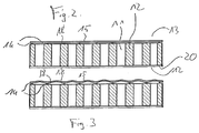
- Fig. 2 shows a section along the line II-II Fig. 1 , As Fig. 2 can be removed, with respect to the base body 10 on the front side 12, a front cover, which is concretely designed as a fiber element 20, but may also be constructed differently arranged.
- the fiber element 20 may be formed in particular as a nonwoven fabric, for example as a glass fiber fleece.
- a plaster (not shown in the figures) may be applied.
- Fig. 3 shows a section analog Fig. 2 , wherein, however, the state of the cover 15 is shown schematically with an applied sound pulse (not to scale).
- the cover 15 is freely oscillated not only on the perforations 11, but also in the edge region 18, the oscillatory portion of the cover 15 is increased and it can greater vibration amplitudes of the cover can be achieved.
- the mounting surface 16 (see Fig. 1 ) extends not only over an edge region of the sound-absorbing building board, but also into the interior. This achieves a robust attachment.
- a thickness of the edge region may be about 5% (10%, 15%, 20%, 30% or 40%) of a line extending radially inward from a rim 21 of the sound-absorbing building board to a center of the building board.
- Fig. 4 shows an alternative embodiment of a sound-absorbing building panel in a schematic view of the back 13 (see with respect to the back Fig. 2 ).
- the perforations 11 are arranged like a grid, wherein each four perforations 11 occupy a quadratic constellation to each other (square grid).
- the difference from the embodiment according to Fig. 1 is that a total of a smaller number of adhesive strips 14 is formed. Concretely, an adhesive strip is arranged only after every second row and column of perforations. As a result, four adjacent perforations 11 each are surrounded by the associated fastening region 19.
- the mounting surface 16 with respect to the embodiment according to Fig.
- any number of adjacent perforations 11 can be enclosed by an associated fastening area.
- Fig. 5 shows a sound absorption frequency diagram, wherein the sound absorption coefficient ⁇ is assigned to the vertical axis and the frequency (in Hertz) is assigned to the horizontal axis.
- the curve 22 (in which individual measuring points are marked with squares) runs over the greater part of the frequency spectrum, especially at small and medium frequencies clearly above the curve 23 (in which individual measuring points are indicated by triangles).
- the curve 22 corresponds to a measurement in which a sound-absorbing building panel according to the invention has been used.
- the curve 23 corresponds to a measurement in which a corresponding cover has been glued over its entire surface to the base body.
- the same sound-absorbing building board was used (thickness 12.5 mm, hole proportion 19.4%, 45 x 75 rows of holes, extension 1250 x 2000 mm, surface density approx. 8.12 kg / m 2 , front side) Cover glass fleece, back cover polyethylene film).
- the measurement was carried out according to DIN standard.
- a curve 24 (in which individual measuring points are marked with circles) corresponds to a measurement analogous to curves 22 and 23, but with the cover used is a microperforated polycarbonate film which has been glued over the entire surface of the base body.
- a curve 25 (in which individual measuring points are indicated by diamonds) corresponds to a measurement with a polyethylene film as a cover, the other measurement parameters differing slightly in some cases from the measurements according to the curves 22 to 24 (thickness of the building board 12.5 mm, hole proportion 20.8%, 45 x 77 rows of holes, expansion 1196 x 1996 mm, areal density 8.06 kg / m 2 , front covering glass fleece).
- the bonds according to the measurement analogous to curve 25 was punctiform and full-surface, which means that adhesive was distributed over the entire back of the body 10, but also between the corresponding adhesive areas larger spaces were available.
Landscapes
- Engineering & Computer Science (AREA)
- Physics & Mathematics (AREA)
- Architecture (AREA)
- Electromagnetism (AREA)
- Civil Engineering (AREA)
- Structural Engineering (AREA)
- Acoustics & Sound (AREA)
- Multimedia (AREA)
- Building Environments (AREA)
Description
- Die Erfindung betrifft eine schallabsorbierende Bauplatte, insbesondere zur Wand- oder Deckenmontage, mit einer einer Schallquelle zugewandten Vorderseite, einer der Schallquelle abgewandten Rückseite und einer Vielzahl von Perforationen, die sich von der Vorderseite durch die schallabsorbierende Bauplatte zur Rückseite erstrecken, wobei die Perforationen rückseitig mit mindestens einer Abdeckung abgedeckt sind.
- Perforierte Bauplatten zur Schallabsorption sind im Stand der Technik bekannt. Unter Schallabsorption versteht man üblicherweise die Minderung der Schallenergie in einem Raum. Schallabsorption ist der Verlust von Schallenergie beim Auftreffen an Begrenzungsflächen, Gegenständen oder Personen, die sich in einem Raum befinden. Der Verlust entsteht vorwiegend durch die Umwandlung von Schall in Wärme (Dissipation). Der Schallabsorptionsgrad beschreibt das Verhältnis der nicht reflektierten zur auftreffenden Schallenergie. Dieser Schallabsorptionsgrad α kann durch den Einsatz von Löchern im jeweiligen Schallabsorptionselement, wie beispielsweise Decken-, Boden- oder Wandplatten, erhöht werden.
- Ein Nachteil dieser durchlöcherten Platten besteht darin, dass Schmutzpartikel aufgrund des durch die Löcher selbst ermöglichten Luftaustauschs transportiert werden und entsprechend im Bereich der Löcher abgelagert werden. Wird die einem Innenraum zugewandte Seite der Bauplatte mit einem luftdurchlässigen Putz belegt, der die Löcher optisch abdeckt, so zeichnen sich diese dennoch nach einiger Zeit aufgrund der Luftbewegungen und dem damit verbundenen Schmutzteilchentransport bzw. der damit verbundenen Schmutzteilchenablagerung unschön ab. Die Optik der jeweiligen Bauplatten, die zunehmend auch zur Verbesserung der Gesamtoptik von Räumen eingesetzt wird, wird dadurch erheblich verschlechtert.
- Aufgrund der beschriebenen Nachteile werden teilweise im Stand der Technik Folienelemente eingesetzt, die über die jeweiligen mit Löchern versehenen Bauplatten rückseitig, also dem Raum abgewandt, vollflächig aufgeklebt werden. Dadurch werden ein Lufttransport und eine damit verbundene Schmutzteilchenablagerung im Bereich der Löcher größtenteils unterbunden. Messungen haben jedoch ergeben, dass der Schallabsorptionsgrad derartiger mit Folienelementen versehener Bauplatten gegenüber Bauplatten, die keine Folienelemente aufweisen, erheblich reduziert In Dokument
DE 87 05 270 U1 ist eine Schallabsorptionsplatte mit den folgenden Merkmalen offenbart:Schallabsorbierende Bauplatte, insbesondere zur Wand- oder Deckenmontage, umfassend eine Gipskartonplatte mit einer einer Schallquelle zugewandten Vorderseite, einer der Schallquelle abgewandten Rückseite und einer Vielzahl von Perforationen, die eine vorbestimmte Geometrie, mit rundem Querschnitt aufweisen und sich von der Vorderseite durch die Gipskartonplatte zur Rückseite erstrecken, und eine im Wesentlichen luftundurchlässige Abdeckung, wobei die Perforation rückseitig mit der mindestens einen Abdeckung abgedeckt sind, wobei die mindestens eine rückseitige Abdeckung mit der Rückseite der Gipskartonplatte der Bauplatte verklebt ist.In DokumentUS 3 770 560 A ist ein Schallabsorbierendes Element offenbart, bei dem die Verklebung so ausgeführt wird, wobei verhindert wird, dass Klebstoff in die Perforationen eindringt. - Der Erfindung liegt die Aufgabe zugrunde, eine schallabsorbierende Bauplatte, insbesondere zur Wand- oder Deckenmontage aufzuzeigen, die einerseits auch längerfristig ein ansprechendes optisches Äußeres beibehält und andererseits einen zufriedenstellenden Schallabsorptionsgrad aufweist. Diese Aufgabe wird durch eine schallabsorbierende Bauplatte nach Patentanspruch 1 gelöst.
- Ein wesentlicher Punkt der Erfindung liegt darin, dass die rückseitige Abdeckung nicht vollflächig mit der Rückseite des Grundkörpers der Bauplatte verklebt ist und insbesondere in der Nähe der Löcher eine feste Verbindung mindestens teilweise unterbleibt. Dadurch wird der Schallabsorptionsgrad α gegenüber einer vollflächigen Verbindung der Abdeckung mit dem Grundkörper deutlich erhöht. Ein auf die perforierte Bauplatte treffender Schallimpuls führt zu einem teilweisen Anheben bzw. Schwingen der rückseitigen Abdeckung und zwar nicht nur in dem Bereich, in dem die Löcher liegen, sondern auch zumindest in einem Randbereich, der an die Löcher angrenzt. Dadurch kann zusätzlich Energie von dem Schallimpuls auf die Bauplatte bzw. die bereichsweise freischwingende Abdeckung übertragen werden, was deren Schallabsorptionsgrad α erhöht. Ein Luftaustausch zwischen Rück- und Vorderseite der Bauplatte wird reduziert oder gänzlich vermieden, was die Ablagerung von Schmutzteilchen reduziert oder gar völlig vermeidet, was den optischen Gesamteindruck verbessert.
- Vorzugsweise ist ein Abschnitt des Grundkörpers der Bauplatte mit einer Perforation oder einer Gruppe von mindestens zwei benachbarten Perforationen rückseitig mit der Abdeckung derart fest verbunden, insbesondere verklebt, dass die jeweiligen Perforationen rückseitig von einem zugeordneten Befestigungsbereich luftdicht umschlossen werden, wobei innerhalb des Befestigungsbereichs ein Flächenabschnitt verbleibt, der größer ist als die rückseitigen Perforationsflächen der jeweiligen Perforationen. Ein Luftaustausch mit damit einhergehenden Verschmutzung im Bereich der Löcher wird dadurch praktisch vollständig vermieden, da eine einen weiteren Luftaustausch verhindernde bis auf die Perforation bzw. die Gruppe von Perforationen abgeschlossene Tasche zwischen Grundkörper und Abdeckung gebildet wird.
- In einer bevorzugten Weiterbildung umfasst mindestens eine der rückseitigen Abdeckungen mindestens eine Folie, insbesondere eine ein- oder mehrschichtige Plastikfolie. Dies reduziert den Konstruktions- und Kostenaufwand für die schallabsorbierende Bauplatte. Die Dicke der mindestens einen Folie beträgt vorzugsweise 5-500 µm, weiter vorzugsweise 10-100 µm, noch weiter vorzugsweise 20-50 µm, beispielsweise etwa 30 µm. Die Folie besteht vorzugsweise aus Kunststoff, insbesondere aus Polyethylen.
- In einer weiteren bevorzugten Ausführungsform ist die schallabsorbierende Bauplatte vorderseitig zumindest bereichsweise mit mindestens einem Faserelement, insbesondere Faservlies abgedeckt. Eine derartige Maßnahme steigert weiter die Schallabsorption, wobei das Faserelement zugleich als Grundlage für die Aufbringung eines Verputzes dienen kann.
- Erfindungsgemäß beträgt ein Befestigungsbereichsanteil an der Gesamtfläche der Rückseite der Bauplatte unter Abzug des rückseitigen Perforationsflächenanteils höchstens 90%, weiter vorzugsweise höchstens 50%, noch weiter vorzugsweise höchstens 30%, insbesondere höchstens 10%. Dadurch kann die Schallabsorption weiter gesteigert werden.
- Die schallabsorbierende Bauplatte ist eine Gipsplatte, insbesondere Gipskartonplatte oder Gipsfaserplatte. Gips ist ein vergleichsweise preiswertes Material, was die Kosten für die schallabsorbierende Bauplatte weiter reduziert.
- Vorzugsweise liegt zumindest ein Befestigungsbereich mindestens teilweise innerhalb eines Randbereichs der Rückseite der Bauplatte. Diese Maßnahme erhöht die Stabilität der entsprechenden Befestigung.
- In bevorzugten Ausführungsformen können die Perforationen rasterartig angeordnet sein und/oder einen konstanten Querschnitt aufweisen. Derartige Perforationen können besonders leicht hergestellt werden, was die Kosten für die Konstruktion der schallabsorbierenden Bauplatte weiter senkt. Beispielsweise können die Perforationen mittels einem Fräsverfahren oder einem Gießverfahren hergestellt werden.
- Die Befestigungsfläche umfasst vorzugsweise mehrere Klebestreifen, wobei insbesondere eine erste Gruppe von Klebestreifen bezüglich einer zweiten Gruppe von Klebestreifen im Wesentlichen senkrecht angeordnet ist, so dass eine Kreuzmusteranordnung vorliegt. Eine derartige Befestigungsfläche ist einfach in der Herstellung.
- Weitere Ausführungsformen ergeben sich aus den Unteransprüchen.
- Nachfolgend wird die Erfindung auch hinsichtlich weiterer Merkmale und Vorteile anhand von Ausführungsbeispielen beschrieben, die anhand der Abbildungen näher erläutert werden.
-
- Fig. 1
- eine schallabsorbierende Bauplatte gemäß einer ersten Ausführungsform in einer schematischen Ansicht von oben;
- Fig. 2
- eine Schnittansicht der ersten Ausführungsform entlang der Schnittlinie II-II aus
Fig. 1 ; - Fig. 3
- eine Schnittansicht der ersten Ausführungsform entlang der Schnittlinie II-II aus
Fig. 1 ; - Fig. 4
- eine schallabsorbierende Bauplatte gemäß einer zweiten Ausführungsform in einer schematischen Ansicht von oben; und
- Fig. 5
- ein Schallabsorptions-Frequenz-Diagramm.
- In der nachfolgenden Beschreibung werden für gleiche und gleichwirkende Teile dieselben Bezugsziffern verwendet.
-
Fig. 1 zeigt eine schallabsorbierende Bauplatte gemäß einer ersten Ausführungsform in einer schematischen Ansicht von oben, wobei die Blickrichtung senkrecht auf eine Rückseite 12 der schallabsorbierenden Bauplatte gerichtet ist. Die schallabsorbierende Bauplatte gemäßFig. 1 umfasst einen Grundkörper 10, der im vorliegenden Fall eine quadratische Grundform aufweist und insgesamt im Wesentlichen als Quader ausgebildet ist, aber auch andere Grundformen, wie rechteckige oder allgemein vieleckige oder auch runde oder ovale Grundformen aufweisen kann. Innerhalb des Grundkörpers 10 sind im Querschnitt quadratische und räumlich gesehen quaderförmige Perforationen 11 vorgesehen, die sich von einer Vorderseite 12 (sieheFig. 2 ) zu einer Rückseite 13 hin erstrecken. Auch die Perforationen 11 können jeden beliebigen Querschnitt und räumlich gesehen verschiedene Formen annehmen. Beispielsweise kann der Querschnitt der Perforationen 11 von der Vorderseite 12 zur Rückseite 13 (wegen Rückseite 13 sieheFig. 2 ) hin abnehmen. Die Vorderseite 12 soll im Gebrauch einer Schallquelle zugewandt sein, wobei die Rückseite 13 im Gebrauch der Schallquelle abgewandt sein soll. - Zwischen den Perforationen verlaufen Klebestreifen 14, die eine Abdeckung 15 (siehe
Fig. 2 ) mit dem Grundkörper 10 verbinden. Sowohl die Dicke der Abdeckung 15 als auch der Klebestreifen 14 inFig. 2 sind nicht maßstabsgetreu, wobei sowohl der Klebestreifen 14 als auch die Abdeckung 15 in einer ersten Ausführungsform eine deutlich geringere Dicke (im Verhältnis zum Grundkörper 10) aufweisen. In alternativen Ausführungsformen kann die Dicke von Abdeckung 15 und Klebestreifen 14 auch etwa den Proportionen inFig. 2 entsprechen oder auch größer ausfallen. - Wie
Fig. 1 entnommen werden kann, ist eine erste Gruppe von Klebestreifen 14 in Bezug auf eine zweite Gruppe von Klebestreifen senkrecht verlaufend angeordnet, so dass insgesamt sich kreuzende Klebestreifen ausgebildet sind. Dadurch wird jede Perforation 11 durch je zwei Klebestreifen 14 der ersten Gruppe und je zwei Klebestreifen 14 der zweiten Gruppe vollständig umrahmt, so dass die Perforationen 11 rückseitig im Wesentlichen luftdicht verschlossen werden (falls auch die Abdeckung 15 im Wesentlichen luftdicht ist). Alternativ kann der Klebstoff auch in unterbrochenen Streifen oder nur punktuell aufgebracht werden. Selbstverständlich ist es auch möglich, die Abdeckung 15 ohne den Einsatz von Klebstoffen mit dem Grundkörper 10 zu verbinden, beispielsweise durch Anschweißen oder durch den Einsatz von Befestigungsmitteln, wie Klammern, Nägel, Schrauben od. dgl. Es ist dabei auch denkbar, die Abdeckung 15 lösbar an dem Grundkörper 10 zu befestigen. - Die Abdeckung 15 kann konkret als Folie, wie beispielsweise als Plastikfolie (insbesondere Polyethylen-Folie) ausgebildet sein und eine Dicke von 1 bis 1000 µm, vorzugsweise 5 bis 100 µm, weiter vorzugsweise 10 bis 80 µm und insbesondere 25 bis 35 µm aufweisen.
- Wie weiterhin
Fig. 1 zu entnehmen ist, ist eine durch die Klebestreifen 14 festgelegte Befestigungsfläche 16 kleiner als eine Grundkörperoberfläche 17 des Grundkörpers 10 (insbesondere wenn man die Rückseite der Perforationen 11 nicht berücksichtigt). Dies hat zur Folge, dass die Abdeckung 15 nicht nur oberhalb der Perforationen 11 frei schwingbar ist, sondern auch in an die Perforationen 11 angrenzenden Randbereichen 18 jeweils frei schwingbar ist. Die Perforationen 11 sind je von einem Befestigungsbereich 19, der sich aus Abschnitten von je zwei zueinander senkrechten Klebestreifen 14 zusammensetzt und eine quadratische Form aufweist, umgeben. Die Klebestreifen 14 können auch eine andere Form annehmen, beispielsweise nicht zueinander in zwei Gruppen senkrecht verlaufen. Auch können die Befestigungsbereiche 19 eine andere Form annehmen und beispielsweise separat aufgetragen werden. - Bei dem Grundkörper 10 kann es sich um eine Gipsplatte, beispielsweise eine Gipskartonplatte oder Gipsfaserplatte handeln. Alternativ ist es auch denkbar als Grundkörper Bauplatten anderen Aufbaus oder aus anderen Materialien, beispielsweise aus Kunststoff und/oder Metall einzusetzen.
-
Fig. 2 zeigt einen Schnitt entlang der Linie II-II ausFig. 1 . WieFig. 2 entnommen werden kann, ist in Bezug auf den Grundkörper 10 an der Vorderseite 12 eine vorderseitige Abdeckung, die konkret als Faserelement 20 ausgebildet ist, jedoch auch andersartig aufgebaut sein kann, angeordnet. Das Faserelement 20 kann insbesondere als Faservlies, beispielsweise als Glasfaservlies ausgebildet sein. Auf dem Faserelement 20 kann ein Putz (nicht in den Figuren gezeigt) aufgebracht sein. -
Fig. 3 zeigt einen Schnitt analogFig. 2 , wobei jedoch schematisch der Zustand des Abdeckelementes 15 bei einem anliegenden Schallimpuls (nicht maßstabsgetreu) dargestellt ist. Dadurch, dass die Abdeckung 15 nicht nur über den Perforationen 11 frei schwingbar ist, sondern auch in dem Randbereich 18, wird der schwingungsfähige Anteil der Abdeckung 15 erhöht und es können größere Schwingungsamplituden der Abdeckung erreicht werden. Dadurch kann mehr Schallenergie (insbesondere im niederfrequenten Bereich) auf die Abdeckung 15 und damit die schallabsorbierende Bauplatte übertragen werden, was den Absorptionsgrad derselben erhöht. Die Befestigungsfläche 16 (sieheFig. 1 ) erstreckt sich dabei nicht nur über einen Randbereich der schallabsorbierenden Bauplatte, sondern auch in das Innere. Dadurch wird eine robuste Befestigung erreicht. Eine Dicke des Randbereiches kann etwa 5 % (10 %, 15 %, 20 %, 30 % oder 40 %) einer ausgehend von einem Rand 21 der schallabsorbierenden Bauplatte radial nach innen bis zu einem Zentrum der Bauplatte verlaufenden Linie betragen. -
Fig. 4 zeigt eine alternative Ausführungsform einer schallabsorbierenden Bauplatte in einer schematischen Ansicht auf die Rückseite 13 (siehe bezüglich der RückseiteFig. 2 ). Wie in der Ausführungsform gemäßFig. 1 sind auch hier die Perforationen 11 rasterartig angeordnet, wobei je vier Perforationen 11 eine quadratische Konstellation zueinander einnehmen (quadratisches Gitter). Der Unterschied gegenüber der Ausführungsform gemäßFig. 1 besteht darin, dass insgesamt eine geringere Anzahl von Klebestreifen 14 ausgebildet ist. Konkret ist nur nach jeder zweiten Reihe und Spalte von Perforationen ein Klebestreifen angeordnet. Dies hat zur Folge, dass jeweils vier zueinander benachbarte Perforationen 11 von dem zugeordneten Befestigungsbereich 19 umgeben werden. Insgesamt ist die Befestigungsfläche 16 gegenüber der Ausführungsform nachFig. 1 reduziert, so dass insgesamt eine größere Fläche der Abdeckung 15 frei schwingbar ist. Prinzipiell kann eine beliebige Anzahl von benachbarten Perforationen 11 durch einen zugeordneten Befestigungsbereich umschlossen werden. Insbesondere können beispielsweise je zwei, drei, sechs, acht, neun oder sechzehn Perforationen von je einem zugeordneten Befestigungsbereich 19 rückseitig, vorzugsweise luftdicht, umschlossen sein. -
Fig. 5 zeigt ein Schallabsorptions-Frequenz-Diagramm, wobei der Schallabsorptionsgrad α der vertikal verlaufenden Achse zugeordnet ist und die Frequenz (in Hertz) der horizontal verlaufenden Achse zugeordnet ist. Die Kurve 22 (bei der einzelne Messpunkte mit Quadraten gekennzeichnet sind) verläuft über den größten Teil des Frequenzspektrums, insbesondere bei kleinen und mittleren Frequenzen deutlich über der Kurve 23 (bei der einzelne Messpunkte durch Dreiecke gekennzeichnet sind). Die Kurve 22 entspricht einer Messung, bei der eine erfindungsgemäße schallabsorbierende Bauplatte zum Einsatz gekommen ist. Die Kurve 23 entspricht einer Messung, bei der eine entsprechende Abdeckung vollflächig mit dem Grundkörper verklebt wurde. Mit Ausnahme der Verklebung bzw. Befestigung wurde ansonsten die gleiche schallabsorbierende Bauplatte verwendet (Dicke 12,5 mm, Lochanteil 19,4 %, 45 x 75 Lochreihen, Ausdehnung 1250 x 2000 mm, Flächendichte ca. 8,12 kg/m2, vorderseitige Abdeckung Glasvlies, rückseitige Abdeckung Polyethylen-Folie). Die Messung wurde nach DIN-Standard durchgeführt. Eine Kurve 24 (bei der einzelne Messpunkte mit Kreisen gekennzeichnet sind) entspricht einer Messung analog den Kurven 22 und 23, wobei jedoch als Abdeckung eine mikroperforierte Polykarbonatfolie eingesetzt wurde, die vollflächig auf dem Grundkörper verklebt wurde. Eine Kurve 25 (bei der einzelne Messpunkte durch Rauten gekennzeichnet sind) entspricht einer Messung mit einer Polyethylen-Folie als Abdeckung, wobei die anderen Messparameter teilweise leicht von den Messungen entsprechend den Kurven 22 bis 24 abweichen (Dicke der Bauplatte 12,5 mm, Lochanteil 20,8 %, 45 x 77 Lochreihen, Ausdehnung 1196 x 1996 mm, Flächendichte 8,06 kg/m2, vorderseitige Abdeckung Glasvlies). Die Verklebungen entsprechend der Messung analog Kurve 25 war punktuell und vollflächig, was bedeutet, dass Klebstoff über die gesamte Rückseite des Grundkörpers 10 verteilt war, jedoch auch zwischen den entsprechenden Klebstoffbereichen größere Freiräume vorhanden waren. - An dieser Stelle sei darauf hingewiesen, dass alle oben beschriebenen Teil für sich alleine gesehen und in jeder Kombination, insbesondere die in den Zeichnungen dargestellten Details, als erfindungswesentlich beansprucht werden. Abänderungen hiervon sind dem Fachmann geläufig.
-
- 10
- Grundkörper
- 11
- Perforation
- 12
- Vorderseite
- 13
- Rückseite
- 14
- Klebestreifen
- 15
- Abdeckung
- 16
- Befestigungsfläche
- 17
- Grundkörperoberfläche
- 18
- Randbereich
- 19
- Befestigungsbereich
- 20
- Faserelement
- 21
- Rand (der schallabsorbierenden Bauplatte)
- 22
- Kurve
- 23
- Kurve
- 24
- Kurve
- 25
- Kurve
Claims (14)
- Schallabsorbierende Bauplatte, insbesondere zur Wand- oder Deckenmontage, umfassend eine Gipsplatte (10) mit einer im Einbauzustand einer Schallquelle zugewandten Vorderseite (12), einer im Einbauzustand der Schallquelle abgewandten Rückseite (13) und einer Vielzahl von Perforationen (11), die eine vorbestimmte Geometrie, insbesondere mit rundem, ovalem oder rechteckförmigem Querschnitt aufweisen und sich von der Vorderseite (12) durch die Gipsplatte (10) zur Rückseite (13) erstrecken, und eine im Wesentlichen luftundurchlässige Abdeckung (15), wobei die Perforationen (11) rückseitig mit der mindestens einen Abdeckung (15) abgedeckt sind,
wobei die mindestens eine rückseitige Abdeckung (15) mit der Rückseite (13) der Gipsplatte (10) der Bauplatte derart verbunden, insbesondere verklebt ist, dass eine Befestigungsfläche um mindestens 10 % kleiner ist als eine rückseitige Gesamtfläche der Rückseite (13) der Gipsplatte (10) unter Abzug des rückseitigen Perforationsflächenanteils. - Schallabsorbierende Bauplatte nach Anspruch 1,
dadurch gekennzeichnet, dass
die mindestens eine rückseitige Abdeckung (15) mit der Rückseite (13) der Gipsplatte (10) der Bauplatte derart verbunden, insbesondere verklebt ist, dass
die Abdeckung (15) in einem an einen Rand der Perforationen angrenzenden Randbereich (18) gegenüber mindestens 50% des Randes, vorzugsweise gegenüber 70% des Randes, insbesondere über den gesamten Rand frei schwingbar ist. - Schallabsorbierende Bauplatte nach Anspruch 1 oder 2,
dadurch gekennzeichnet, dass
ein Abschnitt der Gipsplatte (10) mit einer Perforation oder einer Gruppe von mindestens zwei benachbarten Perforationen rückseitig mit der Abdeckung (15) derart fest verbunden, insbesondere verklebt ist, dass die jeweiligen Perforationen (11) rückseitig von einem zugeordneten Befestigungsbereich (19) luftdicht umschlossen sind, wobei innerhalb des Befestigungsbereichs (19) ein Flächenabschnitt verbleibt, der größer ist als die rückseitigen Perforationsflächen der jeweiligen Perforationen. - Schallabsorbierende Bauplatte nach einem der vorhergehenden Ansprüche,
dadurch gekennzeichnet, dass
die mindestens eine rückseitige Abdeckung (15) mindestens eine Folie, insbesondere Plastikfolie umfasst. - Schallabsorbierende Bauplatte nach Anspruch 4,
dadurch gekennzeichnet, dass
eine Dicke der mindestens einen Folie 5-500 µm, vorzugsweise 10-100 µm, weiter vorzugsweise 20-50 µm, beispielsweise etwa 30 µm, beträgt. - Schallabsorbierende Bauplatte nach einem der vorhergehenden Ansprüche,
dadurch gekennzeichnet, dass
die Gipsplatte (10) der schallabsorbierenden Bauplatte vorderseitig zumindest bereichsweise mit mindestens einem Faserelement (20), insbesondere Faservlies abgedeckt ist. - Schallabsorbierende Bauplatte nach einem der vorhergehenden Ansprüche,
dadurch gekennzeichnet, dass
ein Befestigungsflächenanteil an der Gesamtfläche der Rückseite (13) des Grundkörpers der Bauplatte unter Abzug des rückseitigen Perforationsflächenanteils höchstens 50%, weiter vorzugsweise höchstens 30%, insbesondere höchstens 10%, beträgt. - Schallabsorbierende Bauplatte nach einem der vorhergehenden Ansprüche,
dadurch gekennzeichnet, dass
die Gipsplatte (10) eine Gipskartonplatte oder Gipsfaserplatte ist. - Schallabsorbierende Bauplatte nach einem der Ansprüche 4 bis 8,
dadurch gekennzeichnet, dass
die Folie aus Kunststoff, insbesondere Polyethylen, besteht. - Schallabsorbierende Bauplatte nach einem der vorhergehenden Ansprüche,
dadurch gekennzeichnet, dass
ein Kleber zum Befestigen der mindestens einen Abdeckung (15) aus einem thermoplastischen Klebstoff besteht. - Schallabsorbierende Bauplatte nach einem der vorhergehenden Ansprüche,
dadurch gekennzeichnet, dass
die Befestigungsfläche (16) mindestens teilweise innerhalb eines Randbereichs der Rückseite der Bauplatte liegt. - Schallabsorbierende Bauplatte nach einem der vorhergehenden Ansprüche,
dadurch gekennzeichnet, dass
die Perforationen (11) rasterartig angeordnet sind. - Schallabsorbierende Bauplatte nach einem der vorhergehenden Ansprüche,
dadurch gekennzeichnet, dass
die Perforationen (11) einen konstanten Querschnitt aufweisen. - Schallabsorbierende Bauplatte nach einem der vorhergehenden Ansprüche,
dadurch gekennzeichnet, dass
die Befestigungsfläche (16) mehrere Klebestreifen (14) umfasst, wobei insbesondere eine erste Gruppe von Klebestreifen bezüglich einer zweiten Gruppe von Klebestreifen im Wesentlichen senkrecht angeordnet ist, so dass eine Kreuzmusteranordnung vorliegt.
Priority Applications (1)
| Application Number | Priority Date | Filing Date | Title |
|---|---|---|---|
| SI200931482A SI2408976T1 (sl) | 2009-03-16 | 2009-03-16 | Gradbena panelna plošča za absorbiranje zvoka |
Applications Claiming Priority (1)
| Application Number | Priority Date | Filing Date | Title |
|---|---|---|---|
| PCT/EP2009/053053 WO2010105655A1 (de) | 2009-03-16 | 2009-03-16 | Schallabsorbierende bauplatte |
Publications (3)
| Publication Number | Publication Date |
|---|---|
| EP2408976A1 EP2408976A1 (de) | 2012-01-25 |
| EP2408976B1 EP2408976B1 (de) | 2016-05-11 |
| EP2408976B9 true EP2408976B9 (de) | 2016-09-28 |
Family
ID=41432756
Family Applications (1)
| Application Number | Title | Priority Date | Filing Date |
|---|---|---|---|
| EP09779150.3A Active EP2408976B9 (de) | 2009-03-16 | 2009-03-16 | Schallabsorbierende bauplatte |
Country Status (6)
| Country | Link |
|---|---|
| EP (1) | EP2408976B9 (de) |
| CN (2) | CN101839025A (de) |
| DK (1) | DK2408976T3 (de) |
| HK (1) | HK1217929A1 (de) |
| SI (1) | SI2408976T1 (de) |
| WO (1) | WO2010105655A1 (de) |
Cited By (1)
| Publication number | Priority date | Publication date | Assignee | Title |
|---|---|---|---|---|
| WO2025178820A1 (en) * | 2024-02-19 | 2025-08-28 | Usg Interiors, Llc | Perforated drywall panel |
Families Citing this family (7)
| Publication number | Priority date | Publication date | Assignee | Title |
|---|---|---|---|---|
| US8770345B2 (en) | 2012-06-27 | 2014-07-08 | Usg Interiors, Llc | Gypsum-panel acoustical monolithic ceiling |
| US8684134B2 (en) | 2012-06-27 | 2014-04-01 | Usg Interiors, Llc | Gypsum-panel acoustical monolithic ceiling |
| US8925677B2 (en) | 2012-06-27 | 2015-01-06 | Usg Interiors, Llc | Gypsum-panel acoustical monolithic ceiling |
| CA2905079C (en) * | 2013-03-15 | 2017-02-21 | Usg Interiors, Llc | Gypsum-panel acoustical monolithic ceiling |
| PL3394360T3 (pl) * | 2015-12-21 | 2026-03-09 | Knauf Gips Kg | Akustyczna płyta do suchej zabudowy |
| CN107013000B (zh) * | 2016-10-14 | 2019-01-04 | 百安力钢结构应用科技有限公司 | 消声围护板及围护系统 |
| CN111305406B (zh) * | 2020-03-05 | 2021-05-04 | 河南科技大学 | 一种防风隔音板 |
Family Cites Families (13)
| Publication number | Priority date | Publication date | Assignee | Title |
|---|---|---|---|---|
| US1554180A (en) * | 1924-10-10 | 1925-09-15 | Dahlberg & Company | Sound-absorbing board for walls and ceilings |
| US3020184A (en) * | 1955-09-30 | 1962-02-06 | Patent & Licensing Corp | Sound dampening composition |
| DE1484960A1 (de) * | 1964-08-06 | 1969-03-06 | Rheinhold & Mahla Gmbh | Versetzbares schalldaemmendes Wandelement |
| US3770560A (en) * | 1971-10-21 | 1973-11-06 | American Cyanamid Co | Composite laminate with a thin, perforated outer layer and cavitated bonded backing member |
| DE2947607C2 (de) * | 1979-11-26 | 1985-01-24 | Fa. Carl Freudenberg, 6940 Weinheim | Luftschallschluckende Verkleidung für eine Wand oder Decke |
| DE3445231A1 (de) * | 1984-12-12 | 1986-06-19 | Holzwerke H. Wilhelmi Gmbh & Co Kg, 6335 Lahnau | Schallschluckende bauplatte |
| DE8705270U1 (de) * | 1987-04-09 | 1987-07-02 | Stotmeister GmbH, 7894 Stühlingen | Schallabsorbierende Vorsatzschale für Decken und Wände |
| DE8804962U1 (de) * | 1988-04-15 | 1988-05-26 | Gebr. Knauf Westdeutsche Gipswerke, 8715 Iphofen | Verbundplatte für schallabsorbierende Wand- und Deckenbekleidung |
| CN2176389Y (zh) * | 1993-12-27 | 1994-09-07 | 杨超群 | 隐缝式铝合金吸音装饰板 |
| CN2263307Y (zh) * | 1996-04-23 | 1997-09-24 | 王春生 | 空调器噪声消音板 |
| CN1281404C (zh) * | 2002-03-26 | 2006-10-25 | 宇部日东化成株式会社 | 空心结构板及其制造方法、制造装置以及吸音结构板 |
| CN2673975Y (zh) * | 2003-11-21 | 2005-01-26 | 王晓明 | 多层微孔消音透气板 |
| NL1030971C2 (nl) * | 2006-01-20 | 2007-07-23 | Coatacoustic B V | Akoestisch plaatelement, alsmede plafond of wand met een dergelijk plaatelement. |
-
2009
- 2009-03-16 WO PCT/EP2009/053053 patent/WO2010105655A1/de not_active Ceased
- 2009-03-16 SI SI200931482A patent/SI2408976T1/sl unknown
- 2009-03-16 EP EP09779150.3A patent/EP2408976B9/de active Active
- 2009-03-16 DK DK09779150.3T patent/DK2408976T3/en active
- 2009-09-08 CN CN200910169907A patent/CN101839025A/zh active Pending
- 2009-09-08 CN CN201510548983.7A patent/CN105201090A/zh active Pending
-
2016
- 2016-05-23 HK HK16105876.0A patent/HK1217929A1/zh unknown
Cited By (1)
| Publication number | Priority date | Publication date | Assignee | Title |
|---|---|---|---|---|
| WO2025178820A1 (en) * | 2024-02-19 | 2025-08-28 | Usg Interiors, Llc | Perforated drywall panel |
Also Published As
| Publication number | Publication date |
|---|---|
| DK2408976T3 (en) | 2016-08-22 |
| HK1217929A1 (zh) | 2017-01-27 |
| EP2408976B1 (de) | 2016-05-11 |
| SI2408976T1 (sl) | 2016-09-30 |
| EP2408976A1 (de) | 2012-01-25 |
| CN105201090A (zh) | 2015-12-30 |
| WO2010105655A1 (de) | 2010-09-23 |
| CN101839025A (zh) | 2010-09-22 |
Similar Documents
| Publication | Publication Date | Title |
|---|---|---|
| EP2408976B1 (de) | Schallabsorbierende bauplatte | |
| WO2000014353A1 (de) | Plattenförmiges bauelement | |
| DE202007017699U1 (de) | Trennwandelement | |
| EP0023618B1 (de) | Schallschluckende Bauplatte und Verfahren zu ihrer Herstellung | |
| DE29803674U1 (de) | Schichtstoff | |
| DE102013224145A1 (de) | Schalldämpfende Sandwichplatte | |
| DE2758041C2 (de) | Verwendung eines aus mindestens zwei übereinander angeordneten Folien, insbesondere Kunststoffolien, bestehenden Bauelements | |
| EP2388389A2 (de) | Dampfisolierende Wandverkleidung | |
| DE202010015743U1 (de) | Gebäudeumhüllungselement mit thermischem Isolierelement | |
| EP2000606A2 (de) | Decken- oder Wandelement | |
| EP2181226B1 (de) | Schallabsorber | |
| WO2011110172A1 (de) | Dekorplatte mit witterungsbeständiger deckplatte | |
| DE202022002917U1 (de) | Plattenförmiges Element für die Wand- und Deckenverkleidung | |
| DE102012206187A1 (de) | Deckenelement | |
| EP2960389A1 (de) | Akustikabsorber | |
| EP4040050A1 (de) | Flächenwärmetauscher und verfahren zur einrichtung einer gebäuderaumklimatisierung | |
| DE102007040394B4 (de) | Wandnischeneinsatz und zur Herstellung geeingneter Bausatz | |
| DE3643480A1 (de) | Schallabsorbierende wand- oder deckenverkleidung | |
| DE202012101992U1 (de) | Kassettierter Mehrschicht Absorber | |
| DE102013005371A1 (de) | Lochplatte auf Basis von Gips sowie Verfahren zum Verlegen derselben | |
| DE69409065T2 (de) | Schalldämmende Platte | |
| DE19640402C2 (de) | Schalldämmendes Verbundelement | |
| EP1270837A2 (de) | Wärmedämmung von Wänden und/oder Decken von Gebäuden | |
| DE202021101571U1 (de) | Einsatzmodul für ein Wandelement und Wandelement mit Einsatzmodul | |
| DE4206615A1 (de) | Schallschluckende bauplatte |
Legal Events
| Date | Code | Title | Description |
|---|---|---|---|
| PUAI | Public reference made under article 153(3) epc to a published international application that has entered the european phase |
Free format text: ORIGINAL CODE: 0009012 |
|
| 17P | Request for examination filed |
Effective date: 20110906 |
|
| AK | Designated contracting states |
Kind code of ref document: A1 Designated state(s): AT BE BG CH CY CZ DE DK EE ES FI FR GB GR HR HU IE IS IT LI LT LU LV MC MK MT NL NO PL PT RO SE SI SK TR |
|
| DAX | Request for extension of the european patent (deleted) | ||
| 17Q | First examination report despatched |
Effective date: 20120814 |
|
| GRAP | Despatch of communication of intention to grant a patent |
Free format text: ORIGINAL CODE: EPIDOSNIGR1 |
|
| RIC1 | Information provided on ipc code assigned before grant |
Ipc: E04B 9/34 20060101ALI20151015BHEP Ipc: G10K 11/168 20060101ALI20151015BHEP Ipc: E04B 9/04 20060101ALI20151015BHEP Ipc: E04B 1/86 20060101AFI20151015BHEP Ipc: E04B 1/84 20060101ALN20151015BHEP |
|
| RIC1 | Information provided on ipc code assigned before grant |
Ipc: E04B 1/84 20060101ALN20151028BHEP Ipc: E04B 9/34 20060101ALI20151028BHEP Ipc: G10K 11/168 20060101ALI20151028BHEP Ipc: E04B 1/86 20060101AFI20151028BHEP Ipc: E04B 9/04 20060101ALI20151028BHEP |
|
| INTG | Intention to grant announced |
Effective date: 20151118 |
|
| GRAS | Grant fee paid |
Free format text: ORIGINAL CODE: EPIDOSNIGR3 |
|
| GRAA | (expected) grant |
Free format text: ORIGINAL CODE: 0009210 |
|
| AK | Designated contracting states |
Kind code of ref document: B1 Designated state(s): AT BE BG CH CY CZ DE DK EE ES FI FR GB GR HR HU IE IS IT LI LT LU LV MC MK MT NL NO PL PT RO SE SI SK TR |
|
| REG | Reference to a national code |
Ref country code: GB Ref legal event code: FG4D Free format text: NOT ENGLISH |
|
| REG | Reference to a national code |
Ref country code: CH Ref legal event code: EP |
|
| REG | Reference to a national code |
Ref country code: AT Ref legal event code: REF Ref document number: 798804 Country of ref document: AT Kind code of ref document: T Effective date: 20160515 |
|
| REG | Reference to a national code |
Ref country code: IE Ref legal event code: FG4D Free format text: LANGUAGE OF EP DOCUMENT: GERMAN |
|
| REG | Reference to a national code |
Ref country code: DE Ref legal event code: R096 Ref document number: 502009012575 Country of ref document: DE |
|
| REG | Reference to a national code |
Ref country code: CH Ref legal event code: NV Representative=s name: FIAMMENGHI-FIAMMENGHI, CH |
|
| REG | Reference to a national code |
Ref country code: SE Ref legal event code: TRGR |
|
| REG | Reference to a national code |
Ref country code: NL Ref legal event code: FP |
|
| REG | Reference to a national code |
Ref country code: DK Ref legal event code: T3 Effective date: 20160819 |
|
| REG | Reference to a national code |
Ref country code: LT Ref legal event code: MG4D |
|
| REG | Reference to a national code |
Ref country code: NO Ref legal event code: T2 Effective date: 20160511 |
|
| PG25 | Lapsed in a contracting state [announced via postgrant information from national office to epo] |
Ref country code: LT Free format text: LAPSE BECAUSE OF FAILURE TO SUBMIT A TRANSLATION OF THE DESCRIPTION OR TO PAY THE FEE WITHIN THE PRESCRIBED TIME-LIMIT Effective date: 20160511 |
|
| PG25 | Lapsed in a contracting state [announced via postgrant information from national office to epo] |
Ref country code: GR Free format text: LAPSE BECAUSE OF FAILURE TO SUBMIT A TRANSLATION OF THE DESCRIPTION OR TO PAY THE FEE WITHIN THE PRESCRIBED TIME-LIMIT Effective date: 20160812 Ref country code: HR Free format text: LAPSE BECAUSE OF FAILURE TO SUBMIT A TRANSLATION OF THE DESCRIPTION OR TO PAY THE FEE WITHIN THE PRESCRIBED TIME-LIMIT Effective date: 20160511 Ref country code: ES Free format text: LAPSE BECAUSE OF FAILURE TO SUBMIT A TRANSLATION OF THE DESCRIPTION OR TO PAY THE FEE WITHIN THE PRESCRIBED TIME-LIMIT Effective date: 20160511 Ref country code: PT Free format text: LAPSE BECAUSE OF FAILURE TO SUBMIT A TRANSLATION OF THE DESCRIPTION OR TO PAY THE FEE WITHIN THE PRESCRIBED TIME-LIMIT Effective date: 20160912 |
|
| PG25 | Lapsed in a contracting state [announced via postgrant information from national office to epo] |
Ref country code: IT Free format text: LAPSE BECAUSE OF FAILURE TO SUBMIT A TRANSLATION OF THE DESCRIPTION OR TO PAY THE FEE WITHIN THE PRESCRIBED TIME-LIMIT Effective date: 20160511 |
|
| PG25 | Lapsed in a contracting state [announced via postgrant information from national office to epo] |
Ref country code: CZ Free format text: LAPSE BECAUSE OF FAILURE TO SUBMIT A TRANSLATION OF THE DESCRIPTION OR TO PAY THE FEE WITHIN THE PRESCRIBED TIME-LIMIT Effective date: 20160511 Ref country code: RO Free format text: LAPSE BECAUSE OF FAILURE TO SUBMIT A TRANSLATION OF THE DESCRIPTION OR TO PAY THE FEE WITHIN THE PRESCRIBED TIME-LIMIT Effective date: 20160511 Ref country code: SK Free format text: LAPSE BECAUSE OF FAILURE TO SUBMIT A TRANSLATION OF THE DESCRIPTION OR TO PAY THE FEE WITHIN THE PRESCRIBED TIME-LIMIT Effective date: 20160511 Ref country code: EE Free format text: LAPSE BECAUSE OF FAILURE TO SUBMIT A TRANSLATION OF THE DESCRIPTION OR TO PAY THE FEE WITHIN THE PRESCRIBED TIME-LIMIT Effective date: 20160511 |
|
| REG | Reference to a national code |
Ref country code: DE Ref legal event code: R097 Ref document number: 502009012575 Country of ref document: DE |
|
| PG25 | Lapsed in a contracting state [announced via postgrant information from national office to epo] |
Ref country code: PL Free format text: LAPSE BECAUSE OF FAILURE TO SUBMIT A TRANSLATION OF THE DESCRIPTION OR TO PAY THE FEE WITHIN THE PRESCRIBED TIME-LIMIT Effective date: 20160511 |
|
| PLBE | No opposition filed within time limit |
Free format text: ORIGINAL CODE: 0009261 |
|
| STAA | Information on the status of an ep patent application or granted ep patent |
Free format text: STATUS: NO OPPOSITION FILED WITHIN TIME LIMIT |
|
| REG | Reference to a national code |
Ref country code: FR Ref legal event code: PLFP Year of fee payment: 9 |
|
| 26N | No opposition filed |
Effective date: 20170214 |
|
| PGFP | Annual fee paid to national office [announced via postgrant information from national office to epo] |
Ref country code: FR Payment date: 20170327 Year of fee payment: 9 Ref country code: NL Payment date: 20170327 Year of fee payment: 9 |
|
| PGFP | Annual fee paid to national office [announced via postgrant information from national office to epo] |
Ref country code: LU Payment date: 20170327 Year of fee payment: 9 Ref country code: BE Payment date: 20170328 Year of fee payment: 9 |
|
| PG25 | Lapsed in a contracting state [announced via postgrant information from national office to epo] |
Ref country code: LV Free format text: LAPSE BECAUSE OF NON-PAYMENT OF DUE FEES Effective date: 20170316 Ref country code: MC Free format text: LAPSE BECAUSE OF FAILURE TO SUBMIT A TRANSLATION OF THE DESCRIPTION OR TO PAY THE FEE WITHIN THE PRESCRIBED TIME-LIMIT Effective date: 20160511 |
|
| REG | Reference to a national code |
Ref country code: IE Ref legal event code: MM4A |
|
| REG | Reference to a national code |
Ref country code: SI Ref legal event code: KO00 Effective date: 20171208 |
|
| PG25 | Lapsed in a contracting state [announced via postgrant information from national office to epo] |
Ref country code: IE Free format text: LAPSE BECAUSE OF NON-PAYMENT OF DUE FEES Effective date: 20170316 Ref country code: SI Free format text: LAPSE BECAUSE OF NON-PAYMENT OF DUE FEES Effective date: 20170317 |
|
| PGFP | Annual fee paid to national office [announced via postgrant information from national office to epo] |
Ref country code: FI Payment date: 20180321 Year of fee payment: 10 |
|
| REG | Reference to a national code |
Ref country code: AT Ref legal event code: MM01 Ref document number: 798804 Country of ref document: AT Kind code of ref document: T Effective date: 20170316 |
|
| PG25 | Lapsed in a contracting state [announced via postgrant information from national office to epo] |
Ref country code: AT Free format text: LAPSE BECAUSE OF NON-PAYMENT OF DUE FEES Effective date: 20170316 |
|
| PG25 | Lapsed in a contracting state [announced via postgrant information from national office to epo] |
Ref country code: MT Free format text: LAPSE BECAUSE OF FAILURE TO SUBMIT A TRANSLATION OF THE DESCRIPTION OR TO PAY THE FEE WITHIN THE PRESCRIBED TIME-LIMIT Effective date: 20160511 |
|
| REG | Reference to a national code |
Ref country code: NL Ref legal event code: MM Effective date: 20180401 |
|
| REG | Reference to a national code |
Ref country code: BE Ref legal event code: MM Effective date: 20180331 |
|
| PG25 | Lapsed in a contracting state [announced via postgrant information from national office to epo] |
Ref country code: LU Free format text: LAPSE BECAUSE OF NON-PAYMENT OF DUE FEES Effective date: 20180316 Ref country code: NL Free format text: LAPSE BECAUSE OF NON-PAYMENT OF DUE FEES Effective date: 20180401 |
|
| PG25 | Lapsed in a contracting state [announced via postgrant information from national office to epo] |
Ref country code: BE Free format text: LAPSE BECAUSE OF NON-PAYMENT OF DUE FEES Effective date: 20180331 |
|
| PG25 | Lapsed in a contracting state [announced via postgrant information from national office to epo] |
Ref country code: FR Free format text: LAPSE BECAUSE OF NON-PAYMENT OF DUE FEES Effective date: 20180331 |
|
| PGFP | Annual fee paid to national office [announced via postgrant information from national office to epo] |
Ref country code: IT Payment date: 20190429 Year of fee payment: 15 Ref country code: NO Payment date: 20190322 Year of fee payment: 11 |
|
| PG25 | Lapsed in a contracting state [announced via postgrant information from national office to epo] |
Ref country code: HU Free format text: LAPSE BECAUSE OF FAILURE TO SUBMIT A TRANSLATION OF THE DESCRIPTION OR TO PAY THE FEE WITHIN THE PRESCRIBED TIME-LIMIT; INVALID AB INITIO Effective date: 20090316 |
|
| PG25 | Lapsed in a contracting state [announced via postgrant information from national office to epo] |
Ref country code: BG Free format text: LAPSE BECAUSE OF FAILURE TO SUBMIT A TRANSLATION OF THE DESCRIPTION OR TO PAY THE FEE WITHIN THE PRESCRIBED TIME-LIMIT Effective date: 20160511 |
|
| PG25 | Lapsed in a contracting state [announced via postgrant information from national office to epo] |
Ref country code: CY Free format text: LAPSE BECAUSE OF NON-PAYMENT OF DUE FEES Effective date: 20160511 Ref country code: FI Free format text: LAPSE BECAUSE OF NON-PAYMENT OF DUE FEES Effective date: 20190316 |
|
| PG25 | Lapsed in a contracting state [announced via postgrant information from national office to epo] |
Ref country code: MK Free format text: LAPSE BECAUSE OF FAILURE TO SUBMIT A TRANSLATION OF THE DESCRIPTION OR TO PAY THE FEE WITHIN THE PRESCRIBED TIME-LIMIT Effective date: 20160511 |
|
| PG25 | Lapsed in a contracting state [announced via postgrant information from national office to epo] |
Ref country code: TR Free format text: LAPSE BECAUSE OF FAILURE TO SUBMIT A TRANSLATION OF THE DESCRIPTION OR TO PAY THE FEE WITHIN THE PRESCRIBED TIME-LIMIT Effective date: 20160511 |
|
| PG25 | Lapsed in a contracting state [announced via postgrant information from national office to epo] |
Ref country code: IS Free format text: LAPSE BECAUSE OF FAILURE TO SUBMIT A TRANSLATION OF THE DESCRIPTION OR TO PAY THE FEE WITHIN THE PRESCRIBED TIME-LIMIT Effective date: 20160911 |
|
| REG | Reference to a national code |
Ref country code: NO Ref legal event code: MMEP |
|
| REG | Reference to a national code |
Ref country code: CH Ref legal event code: PL |
|
| PG25 | Lapsed in a contracting state [announced via postgrant information from national office to epo] |
Ref country code: NO Free format text: LAPSE BECAUSE OF NON-PAYMENT OF DUE FEES Effective date: 20200331 Ref country code: CH Free format text: LAPSE BECAUSE OF NON-PAYMENT OF DUE FEES Effective date: 20200331 Ref country code: LI Free format text: LAPSE BECAUSE OF NON-PAYMENT OF DUE FEES Effective date: 20200331 |
|
| P01 | Opt-out of the competence of the unified patent court (upc) registered |
Effective date: 20230822 |
|
| PGFP | Annual fee paid to national office [announced via postgrant information from national office to epo] |
Ref country code: SE Payment date: 20260327 Year of fee payment: 18 |
|
| PGFP | Annual fee paid to national office [announced via postgrant information from national office to epo] |
Ref country code: GB Payment date: 20260327 Year of fee payment: 18 |
|
| PGFP | Annual fee paid to national office [announced via postgrant information from national office to epo] |
Ref country code: DK Payment date: 20260325 Year of fee payment: 18 Ref country code: DE Payment date: 20260327 Year of fee payment: 18 |