EP2407815B1 - Verfahren für die zusammenstellung von formdaten für ein brillenglas, vorrichtung für die zusammenstellung von formdaten für ein brillenglas und brillenglas - Google Patents
Verfahren für die zusammenstellung von formdaten für ein brillenglas, vorrichtung für die zusammenstellung von formdaten für ein brillenglas und brillenglas Download PDFInfo
- Publication number
- EP2407815B1 EP2407815B1 EP10750933.3A EP10750933A EP2407815B1 EP 2407815 B1 EP2407815 B1 EP 2407815B1 EP 10750933 A EP10750933 A EP 10750933A EP 2407815 B1 EP2407815 B1 EP 2407815B1
- Authority
- EP
- European Patent Office
- Prior art keywords
- lens
- shape
- prismatic effect
- eye
- back surface
- Prior art date
- Legal status (The legal status is an assumption and is not a legal conclusion. Google has not performed a legal analysis and makes no representation as to the accuracy of the status listed.)
- Active
Links
- 238000000034 method Methods 0.000 title claims description 122
- 230000000694 effects Effects 0.000 claims description 331
- 238000013461 design Methods 0.000 claims description 112
- 230000003287 optical effect Effects 0.000 claims description 105
- 238000012545 processing Methods 0.000 claims description 56
- 238000012937 correction Methods 0.000 claims description 46
- 230000004438 eyesight Effects 0.000 claims description 31
- 238000005259 measurement Methods 0.000 claims description 12
- 210000001508 eye Anatomy 0.000 description 131
- 238000011156 evaluation Methods 0.000 description 58
- 201000009310 astigmatism Diseases 0.000 description 56
- 210000001747 pupil Anatomy 0.000 description 47
- 210000005252 bulbus oculi Anatomy 0.000 description 24
- 230000000750 progressive effect Effects 0.000 description 24
- 230000008569 process Effects 0.000 description 23
- 230000002093 peripheral effect Effects 0.000 description 18
- 230000005043 peripheral vision Effects 0.000 description 16
- 239000000463 material Substances 0.000 description 9
- 238000007796 conventional method Methods 0.000 description 5
- 238000007688 edging Methods 0.000 description 5
- 238000012546 transfer Methods 0.000 description 5
- 238000000465 moulding Methods 0.000 description 4
- 238000003672 processing method Methods 0.000 description 3
- 238000010586 diagram Methods 0.000 description 2
- 210000005069 ears Anatomy 0.000 description 2
- 230000004075 alteration Effects 0.000 description 1
- 230000008859 change Effects 0.000 description 1
- 230000000295 complement effect Effects 0.000 description 1
- 230000006735 deficit Effects 0.000 description 1
- 230000001419 dependent effect Effects 0.000 description 1
- 239000000428 dust Substances 0.000 description 1
- 239000011344 liquid material Substances 0.000 description 1
- 238000012986 modification Methods 0.000 description 1
- 230000004048 modification Effects 0.000 description 1
- 230000001681 protective effect Effects 0.000 description 1
- 239000000700 radioactive tracer Substances 0.000 description 1
- 210000001525 retina Anatomy 0.000 description 1
- 238000004381 surface treatment Methods 0.000 description 1
- 230000000007 visual effect Effects 0.000 description 1
Images


Classifications
-
- G—PHYSICS
- G02—OPTICS
- G02C—SPECTACLES; SUNGLASSES OR GOGGLES INSOFAR AS THEY HAVE THE SAME FEATURES AS SPECTACLES; CONTACT LENSES
- G02C7/00—Optical parts
- G02C7/02—Lenses; Lens systems ; Methods of designing lenses
- G02C7/024—Methods of designing ophthalmic lenses
-
- G—PHYSICS
- G02—OPTICS
- G02C—SPECTACLES; SUNGLASSES OR GOGGLES INSOFAR AS THEY HAVE THE SAME FEATURES AS SPECTACLES; CONTACT LENSES
- G02C7/00—Optical parts
- G02C7/02—Lenses; Lens systems ; Methods of designing lenses
-
- G—PHYSICS
- G02—OPTICS
- G02C—SPECTACLES; SUNGLASSES OR GOGGLES INSOFAR AS THEY HAVE THE SAME FEATURES AS SPECTACLES; CONTACT LENSES
- G02C7/00—Optical parts
- G02C7/02—Lenses; Lens systems ; Methods of designing lenses
- G02C7/024—Methods of designing ophthalmic lenses
- G02C7/027—Methods of designing ophthalmic lenses considering wearer's parameters
-
- G—PHYSICS
- G06—COMPUTING; CALCULATING OR COUNTING
- G06F—ELECTRIC DIGITAL DATA PROCESSING
- G06F30/00—Computer-aided design [CAD]
-
- G—PHYSICS
- G02—OPTICS
- G02C—SPECTACLES; SUNGLASSES OR GOGGLES INSOFAR AS THEY HAVE THE SAME FEATURES AS SPECTACLES; CONTACT LENSES
- G02C7/00—Optical parts
- G02C7/02—Lenses; Lens systems ; Methods of designing lenses
- G02C7/06—Lenses; Lens systems ; Methods of designing lenses bifocal; multifocal ; progressive
- G02C7/061—Spectacle lenses with progressively varying focal power
Definitions
- the present invention relates to a method for compiling (creating) shape data of a spectacle lens suitable to be fitted into a spectacle frame having a large front angle, such as a wraparound frame and a device for compiling (creating) the shape data of the spectacle lens.
- Wraparound spectacles whose lenses wrap around the eyes and the area close to both sides of the face are proposed to be used as sporting spectacles, sunglass and the like.
- many advantages can be achieved such as obtaining a wide vision, keeping the wind out from the eyes, and controlling incident light from the lateral direction.
- growing demand for the wraparound spectacles comes not only from the sports lovers, but also from the persons engaged in various outdoor activities. Further, there is another growing demand of the wraparound spectacles derived from functionality.
- FIG. 22 is a perspective view showing an example of a spectacle frame 3 for configuring a pair of wraparound spectacles
- FIG. 23 is a plan view of the spectacle frame 3 viewed from above.
- the spectacle frame 3 includes a front 7, and two temples 8 respectively connected to the left and right ends of the front 7.
- the front 7 includes left and right rims 5 for holding the lenses, a bridge 9 for connecting the left and right rims 5, and a pad (nose pad) 4 attached to the inner side of the left and right rims 5.
- left and right lens frame shapes 6, which are respectively the inner periphery shapes of the left and right rims 5, respectively correspond to the left and right lens shapes of the lenses fitted into the spectacle frame 3.
- a front angle ⁇ f is defined as an angle in the horizontal direction between a plane Ff of the front 7 (also referred to as “spectacle plane” hereinafter) of the spectacle frame and a plane F s of each of the left and right lens shapes (referred to as “lens plane” hereinafter).
- the spectacle plane F f is a vertical plane passing through the left and right lens shape centers (each lens shape center being an intersection of the horizontal centerline and the vertical centerline of a rectangle formed by two horizontal lines and two vertical lines circumscribing the lens shape) 2, and the lens plane F s is a vertical plane passing through the horizontal centerline L hc of each lens shape (i.e., the horizontal centerline of the rectangle formed by two horizontal lines and two vertical lines circumscribing the lens shape).
- the front angle ⁇ f is typically set in a range from 10 to 3 0 degrees.
- spectacle lenses with no dioptric power also referred to as “plano lenses” hereinafter
- single-vision spectacle lenses which are spectacle lenses with dioptric power
- spectacle lenses withscribed lenses also used as the spectacle lenses to be fitted into the aforesaid wraparound spectacle frame.
- WO 97/35224 A1 relates to an optical lens element with a prescription zone, suitable for use in wraparound or protective type eyewear.
- the element includes a peripheral vision zone, with no prismatic jump between the zones.
- Design methods for the prescription zone include temporally rotating a prescription section about a vertical axis through the optical center thereof, and/or decentring the optical axis of said prescription section relative to the geometric axis thereof, and providing partial surface correction for astigmatic and/or mean power errors.
- EP 1 882 973 A1 relates to a design method for a spectacle lens mounted in a spectacle frame having a bend angle of 200 degrees or larger.
- the method comprises an astigmatic power adding step on an object side refractive surface or an eyeball side refractive surface of the spectacle lens that adds astigmatic power for canceling aberration caused by the bend angle of the spectacle frame, at a design reference point (D) of the spectacle lens, a step setting prismatic power by tilting the surface, which is on the object side or on the eyeball side of the spectacle lens for canceling prismatic power, caused by the bend angle of the spectacle frame at the design reference point of the spectacle lens, on the assumptions that: a line extending from the design reference point to the edge of the spectacle lens in one direction is a first reference meridian (A1), the direction being a projected direction, when a surface normal line at the design reference point of the spectacle lens is projected on a flat plane crossing the visual axis at right angles, the lens having the bend angle of the spectacle frame, a line
- the method further includes, a first step that sets a plurality of reference meridians including at least the first through fourth reference meridians, a second step that obtains aspherical surface quantities optimizing optical performance on the respective reference meridians after the first step, and a third step that obtains aspherical surface quantities between the reference meridians by interpolation after the second step.
- EP 1 582 909 A1 relates to a spectacle lens designed optically to suit a spectacle frame with a large camber angle such as a wraparound type spectacle frame.
- US 2005/122470 A1 relates to shaped ophthalmic lenses and methods for providing such lenses, including non-powered lenses having non-quadratic surfaces of complementary curvature.
- Such lenses may have a curvature maximum away from an axis of symmetry and a substantially constant wall thickness. Equations describing and methods of designing such lenses are disclosed including embodiments where two spheres of substantially different curvature are merged in accordance with a weighting function, and adjusted using merit functions.
- DE 10 2005 057533 A1 relates to a method for calculation of the local magnification and/or the local distortion of a spectacle lens in at least one predetermined or predeterminable viewing direction, with the spectacle lens being designed to correct a refraction deficit of an eye, and having at least one object-side surface and one second eye-side surface, comprising the following steps: calculation for the predetermined or predeterminable viewing direction of the profile of a main beam which originates from a predetermined or predeterminable infinitesimally small object and, after refraction by the spectacle lens, passes through the rotation point of the eye, through the inlet pupil of the eye or through the main plane of the eye; determination of the main curvatures and directions of a local wavefront associated with the main beam on refraction by the spectacle lens; calculation of the local magnification and/or the local distortion of the spectacle lens from the determined main curvatures and directions of the local wavefront, the data relating to the profile of the main beam, and the data relating to the spectacle lens.
- Patent document 1 Japanese Unexamined Patent Application Publication No. 2005-284059
- FIG. 24 is a view showing the line-of-sight direction of the eyes in the case of a pair of single-vision spectacle lenses designed based on an assumption that the lenses are to be fitted into a frame having no front angle.
- the description given here is based on a case where the left and right single-vision spectacle lenses are spherical lenses having the same positive dioptric power, and the prismatic power of each lens is 0.00 ⁇ .
- the eyes 30L, 30R and their rotation centers 31L, 31R shown in the aforesaid drawings are respectively eyes and rotation centers assumed in optical design of the lenses, and the positional relation between the eyes 30 and the lenses is set based on the information about the pupil distance of the spectacle wearer, the shape of the spectacle frame, and the like.
- the left and right line-of-sights respectively passing through the rotation centers 31L, 31R of the eyes when viewing distant objects with the naked eyes are called "reference front line-of-sights 40L, 40R"; and the aforesaid drawings illustrate a case where the left and right reference front line-of-sights 40L, 40R extend in parallel with each other in the horizontal direction, and respectively pass through the fitting points of the respective lenses.
- the left spectacle lens 1.5L and the right spectacle lens 15R are arranged based on an assumption in optical design so that the fitting points P L , P R on the lens front surfaces (convex surfaces) of the left spectacle lens 15L and the right spectacle lens 15R are situated in the reference front line-of-sights 40L, 40R respectively passing through the rotation centers 31L, 31R of the eyes, and so that, in the horizontal cross sections passing through the fitting points P L , P R , the normal lines N of the lens front surfaces at the fitting points P L , P R are identical to the reference front line-of-sights 40L, 40R.
- a horizontal line orthogonal to the reference front line-of-sights 40L, 40R at the fitting points P L , P R of the left and right lenses is a straight line L.
- a state where the normal lines N are identical to the reference front line-of-sights 40L, 40R in the horizontal cross sections passing through the fitting points P L , P R is also expressed in terms of "having no lens front angle"; and a state where the normal lines N intersect with the reference front line-of-sights 40L, 40R in the horizontal cross sections passing through the fitting points P L , P R so that the normal lines N each form a finite angle not equal to zero toward the outside in the horizontal direction is also expressed in terms of "having lens front angle".
- arrows a L , b L and c L represent the line-of-sights of the left eye 30L
- arrows a Le , b Le and c Le represent image side line-of-sights (i.e., the line-of-sights extending from the rotation center 31L of the eye to the lens 15L) of the respective line-of-sights
- arrows a Lo , b Lo , and c Lo represent object side line-of-sights (i.e., the line-of-sights extending from the lens 15L to the outside) of the respective line-of-sights.
- arrows a R, b R and c R represent the line-of-sights of the right eye 30R
- arrows a Re , b Re and c Re represent image side line-of-sights of the respective line-of-sights
- arrows a Ro , b Ro and c Ro represent object side line-of-sights of the respective line-of-sights.
- the position and direction of the line-of-sight b L passing through the rotation center 31L of the left eye 30L and the position and direction of the line-of-sight b R passing through the rotation center 31R of the right eye 30R are respectively identical to the position and direction of the reference front line-of-sight 40L and the position and direction of the reference front line-ot-sight. 40L.
- the object side line-of-sights a Lo due to the prismatic effect of the lenses 15L, 15R, the object side line-of-sights a Lo , a Ro corresponding to the image side line-of-sights a Le , a Re tilted from the reference front line-of-sights 40L, 40R toward the left side by an angle of ⁇ degrees are refracted toward the reference front line-of-sights 40L, 40R.
- the object side line-of-sights c Lo , c Ro corresponding to the image side line-of-sights c Le , c Re tilted from the reference front line-of-sights 40L, 40R toward the right side by an angle of ⁇ degrees are refracted toward the reference front line-of-sights 40L, 40R.
- the direction of the line-of-sight after being refracted with respect to the image side line-of-sight of the left eye will be identical to the direction of the line-of-sight after being refracted with respect to the image side line-of-sight of the right eye if the image side line-of-sight of the left eye and the image side line-of-sight of the right eye have the same direction.
- the direction of the object side line-of-sight a Lo will be identical to the direction of the object side line-of-sight a Ro ; and if the image side line-of-sight c Le and the image side line-of-sight c Re have the same direction, the direction of the object side line-of-sight c Lo will be identical to the direction of the object side line-of-sight c Ro .
- FIG. 25 the line-of-sight directions obtained in the case where the same lenses 15L, 15R are fitted into a frame having large front angle are shown in FIG. 25 .
- like components are denoted by like reference numerals as of FIG. 24 , and the explanation thereof will be omitted.
- the left and right lenses 15L, 15R are respectively tilted toward the outside in the horizontal direction (i.e., the left and right lenses 15L, 15R each have lens front angle), and therefore when viewing objects in front view, object side line-of-sights b Lo ', b Ro ' of line-of-sights b L ', b R ' will each be subjected to a prismatic effect that refracts the line-of-sight toward the outside (i.e., the side of the ears), so that left and right line-of-sights b Lc ', b Ro ' will have different directions.
- an object side line-of-sight a Lo ' of the left eye 30L corresponding to an image side line-of-sight a Le ' tilted from the reference front line-of-sight 40L toward the left side by an angle of 8 degrees is subjected to a prismatic effect that refracts the line-of-sight toward the outside (i.e., the side of the left ear), and an object side line-of-sight a Ro ' of the right eye 30R corresponding to an image side line-of-sight a Re ' tilted from the reference front line-of-sight 40R toward the left side by an angle of ⁇ degrees is subjected to a prismatic effect that refracts the line-of-sight toward the side of the reference front line-of-sight 40R (i.e., the side of the right ear).
- an object side line-of-sight c Lo ' of the left eye 30L corresponding to an image side line-of-sight c Le ' tilted from the reference front line-of-sight 40L toward the right side by an angle of ⁇ degrees is subjected to a prismatic effect that refracts the line-of-line-of-sight toward the side of the reference front line-of-sight 40L (i.e., the side of the left ear), and an object side line-of-eight c Ro of the right eye 30R corresponding to an image side line-of-sight c Re ' tilted from the reference front line-of-line-of-sight 40R toward the right side by an angle of ⁇ degrees is subjected to a prismatic effect that refracts the line-of-sight toward outside (i.e., the side of the right ear).
- the directions of the line-of-sights after being refracted with respect to the image side line-of-sights of the left and right eyes are divergent from each other, instead of being identical to each other, if the image side line-of-sights of the left and right eyes have the same direction.
- the direction of the object side line-of-sight a Lo ' will be different from the direction of the object side line-of-sight a Rc '; and if the image side line-of-sight c Le ' and the image side line-of-sight c Re ' have the same direction, the direction of the object side line-of-sight c Lo ' will be different from the direction of the object side line-of-sight c Ro '.
- FIG. 26 shows the line-of-sight directions obtained in the case where a pair of lenses 25L, 25R corrected by the aforesaid conventional methods (1) to (4) are fitted into a. frame having the same front angle as FIG. 25 .
- the lenses 25L, 25R are lenses corrected by: employing lenses having a large base curve, adding a correction prism to the lenses in order to offset the extra prismatic effect caused by the line-of-sight when viewing objects in front view, correcting the back surfaces of the lenses so as to remove the astigmatism and the mean power error felt by the line-of-sight of the eye when viewing objects in front view, and forming the back surfaces of the lenses into an aspherical shape so as to reduce the astigmatism and the mean power error felt by the eyes in the area excluding the line-of-sight when viewing objects in front view.
- the lenses 25L, 25R corrected by the aforesaid methods since the correction prism is added, although the positions of the object side line-of-sights b Lo ", b Ro " of the line-of-sights b L ", b R " when viewing objects in front view are shifted toward the outside (i.e., the side of the ears) respectively from the reference front line-of-sights 40L, 40R, the directions of the object side line-of-sights b Lo" , b Ro " are parallel to the reference front line-of-sights 40L, 40R.
- the prismatic effect is reduced compared with the case of FIG. 25 .
- the directions of object side line-of-sights a Lo '', a Ro ", c Lo “, c Ro " corresponding to image side line-of-sights a Le “, a Re “ , c Le “, c Re " tilted from the reference front line-of-sights 40L, 40R toward the left side and right side by an angle degrees are closer to the directions of the object side line-of-sights of FIG. 24 .
- the object side line-of-sights corresponding to the image side line-of-sights of the left and right eyes are divergent from each other, instead of being identical to each other, if the image side line-of-sight of the left eye and the image side line-of-sight of the right eye have the same direction.
- the direction of the object side line-of-sight a Lo " and the direction of the object side line-of-sight a Ro " are different from each other; and the direction of the object side line-of-sight c Lo " and the direction of the object side line-of-sight c Ro " are different from each other.
- FIG. 27A and 27B show an example of a prismatic effect exerted on the eyes calculated based on the lens shown in FIG. 26 which has been corrected by the conventional methods (wherein the lens is a single-vision lens whose data is : base curve is 8.50D; spherical power is +4.00D; center thickness is 8 mm; and prismatic power is 0 ⁇ ), wherein FIG. 27A shows a prismatic effect in horizontal direction undergone by a ray passing through the rotation center, and FIG. 27B shows a prismatic effect in vertical direction undergone by the ray passing through the rotation center.
- These drawings are viewed from the back surface of the left lens, so that the right side is the nose side, and the left side is the ear side.
- the prismatic effect, particularly the prismatic effect in horizontal direction, of the lens is largely unbalanced between left side and the right side.
- the present inventor considers that the cause of the discomfort felt by the wearer is that the conventional methods are designed to reduce the astigmatism and power error when looking in peripheral vision, but not to reduce the imbalance of the prismatic effect between left eye and the right eye; and therefore the present inventor has made the present invention, focusing on reducing the imbalance of the prismatic effect between left eye and the right eye.
- a method is adapted to create shape data of a spectacle lens to be fitted into a spectacle frame in a state where there is lens front angle, wherein the spectacle lens has dioptric power.
- the method comprises a step for creating initial lens shape data by which the shape of a lens front surface and the shape of a lens back surface is determined, and a lens back surface shape data correcting step for correcting the shape data of the lens back surface with respect to the created initial lens shape data.
- the lens back surface shape data correcting step comprises a prismatic effect correcting step for correcting the shape data of the lens back surface so that the prismatic effect undergone via the lens of initial lens shape by a plurality of rays passing through a rotation center of the eye assumed in optical design in a state where there is lens front angle is identical or close to the prismatic effect undergone via the lens of initial lens shape by the plurality of rays passing through the rotation center of the eye assumed in optical design in a state where there is no lens front angle, wherein the plurality of rays include a ray in a front view direction.
- the prismatic effect correcting step comprises: a direction correcting step for correcting the direction of the lens back surface relative to the lens front surface so that the prismatic effect undergone via the lens of initial lens shape by the ray in the front view direction passing through the rotation center of the eye assumed in optical design in a state where there is lens front angle is identical to the prismatic effect undergone via the lens of initial lens shape by the ray in the front view direction passing through the rotation center of the eye assumed in optical design in a state where there is no lens front angle, and a shape correcting step for correcting the shape data of the lens back surface obtained after performing the direction correcting step so that the prismatic effect undergone via the lens of the lens shape after direction correcting step by one or more rays passing through the rotation center of the eye assumed in optical design in a state where there is lens front angle is identical or close to the prismatic effect undergone via the lens of initial lens shape by the one or more rays passing through the rotation center of the eye assumed in optical design in optical design in a state where there is lens front angle is identical
- a method according to a third aspect is adapted to create shape data of a spectacle lens to be fitted into a spectacle frame in a state where there is lens front angle, wherein the spectacle lens has dioptric power.
- the method comprising a step for creating initial lens shape data by which the shape of a lens front surface and the shape of a lens back surface is determined, and a lens back surface shape data correcting step for correcting the shape data of the lens back surface with respect to the created initial lens shape data.
- the lens back surface shape data correcting step comprises a prismatic effect correcting step for correcting the shape data of the lens back surface so that the prismatic effect undergone via the lens of initial lens shape by a plurality of rays passing through an entrance pupil center of the eye when viewing objects in front vision assumed in optical design in a state where there is lens front angle is identical or close to the prismatic effect undergone via the lens of initial lens shape by the plurality of rays passing through the entrance pupil center of the eye when viewing objects in front vision assumed in optical design in a state where there is no lens front angle, wherein the plurality of rays include a ray in the front view direction.
- the prismatic effect correcting step comprises a direction correcting step for correcting the direction of the lens back surface relative to the lens front surface so that the prismatic effect undergone via the lens of initial lens shape by the ray in the front view direction passing through the entrance pupil center of the eye when viewing objects in front vision assumed in optical design in a state where there is lens front angle is identical to the prismatic effect undergone via the lens of initial lens shape by the ray in a front view direction passing through the entrance pupil center of the eye when viewing objects in front vision assumed in optical design in a state where there is no lens front angle, and a shape correcting step for correcting the shape data of the lens back surface obtained after performing the direction correcting step so that the prismatic effect undergone via the lens of the lens shape after direction correcting step by one or more rays passing through the entrance pupil center of the eye when viewing objects in front vision assumed in optical design in a state where there is lens front angle is identical or close to the prismatic effect undergone via the lens of initial lens
- lens back surface shape data correcting step comprises a dioptric power correcting step for correcting the shape data of the lens back surface so that, in a state where the lens having a lens shape obtained after performing the prismatic effect correcting steps has lens front angle, the power of the light acting on the eye in a state where the line-of-sight extends from the rotation center of the eye assumed in optical design to power measurement position of the lens is identical to a prescription value.
- the prismatic effect correcting step is adapted to correct the shape data of the lens back .surface so that the prismatic effect in horizontal direction undergone via the lens of initial lens shape by the plurality of rays passing through the rotation center of the eye assumed in optical design in a state where there is lens front angle is identical or close to the prismatic effect in horizontal direction undergone via the lens of initial lens shape by the plurality of rays passing through the rotation center of the eye assumed in optical design in a state where there is no lens front angle, wherein the plurality of rays include the ray in the front view direction.
- a device is adapted to create shape data of a spectacle lens to be fitted into a spectacle frame in a state where there is lens front angle, wherein the spectacle lens has dioptric power.
- the device comprises: a section for creating initial lens shape data by which the shape of a lens front surface and the shape of a lens back surface is determined and a lens back surface shape data correcting section for correcting the shape data of the lens back surface with respect to the created initial lens shape data.
- the lens back surface shape data correcting section comprises a prismatic effect correcting section for correcting the shape data of the lens back surface so that the prismatic effect undergone via the lens of initial lens shape by a plurality of rays passing through a rotation center of the eye or an entrance pupil center of the eye when viewing objects in front vision assumed in optical design in a state where there is lens front angle is identical or close to the prismatic effect undergone via the lens of initial lens shape by the plurality of rays passing through the rotation center of the eye or the entrance pupil center of the eye when viewing objects in front vision assumed in optical design in a state where there is no lens front angle, wherein the plurality of rays include a ray in a front view direction.
- a spectacle lens according to an eighth aspect is adapted to be fitted into a spectacle frame in a state where there is lens front angle, wherein the spectacle lens has dioptric power.
- the spectacle lens comprises: a lens front surface which is a spherical surface or a rotationally symmetric aspherical surface, and a lens back surface which is a bilaterally asymmetrical aspherical surface or atoroidal surface having been subjected to shape correction so as to reduced imbalance of the prismatic effect between left side and right side and increase astigmatism and mean power error, wherein surface mean power of the lens back surface in a horizontal cross section passing through a fitting point of the lens front surface changes more largely on the ear side than on the nose side relative to the fitting point.
- the present invention like the spectacle lens fitted into a spectacle frame having large front angle, in a prescribed lens fitted into a spectacle frame in a state where there is lens front angle, since correction is performed so that the prismatic effect undergone by the line-of-sights excluding the line-of-sight in the front view direction is identical or close to the prismatic effect of the spectacle lens fitted into a spectacle frame in a state where there is no lens front angle, the bias of the prismatic effect distribution caused by the lens front angle is reduced, and therefore the discomfort felt by the wearer can be reduced.
- the distortion resulting from the lens front angle can be corrected.
- the wearer can obtain a good vision with no feeling of discomfort.
- a first embodiment shows an example in which shape data of a single-vision spectacle lens is created by a method of correcting the imbalance of the prismatic effect resulting from the lens front angle, with respect to the principal fixation line, so as to create the lens shape data.
- a lens shape data creating device 100 to which a lens shape data creating method according to the present embodiment is suitable to be applied, will be described below with reference to FIG. 6.
- FIG. 6 is a block diagram showing the function of the lens shape data creating device 100.
- the lens shape data creating device 100 at least includes a computer 110 for design and calculation, an input section 101, an output section 102 that includes a display, a printer and the like, and a data server 160, wherein the computer 110 for design and calculation is adapted to perform design and calculation process, the input section 101 is adapted to input design conditions and the like to the computer 110 for design and calculation, and operate the design conditions and the like, the output section 102 is adapted to output processing results, and the data server 160 is adapted to store the data necessary for performing design and the designed lens shape data therein.
- the data necessary for performing and the lens shape data calculated by the computer 110 for design and calculation are stored in a storage 170 of the data server 160.
- accepting order data 172 (which is the specification of the lens)
- design data 171 (which includes the initial lens shape data calculated by the computer 110 for design and calculation, and the shape data obtained after performing various kinds of correction process) are stored in the storage 170.
- the accepting order data 172 includes, for example, spectacle lens information, spectacle frame information, prescription value, layout information and the like.
- the spectacle lens information includes lens material, refractive index, type of the optical design of the lens front surface and lens back surface, lens outer diameter, lens thickness, edge thickness, decentering, base curve, shape data of semifinished lens blank, and the like.
- the spectacle frame information includes frame size, frame curve, shape of lens shape, frame shape measured by a frame tracer, and the like.
- the prescription value includes spherical power, cylindrical power, cylinder axis, prismatic power, addition power and the like.
- the layout information includes pupil distance, near pupil distance, segment position, eye point position and the like.
- the computer 110 for design and calculation is connected with the data server 160, so that it is possible for the computer 110 for design and calculation to read necessary information from the data server 160 when creating the lens shape data, and transmit the created lens shape data.
- the computer 110 for design and calculation includes a processing section 120 adapted to perform design and calculation process, and a storage 150 adapted to store the corrected lens shape data therein.
- the processing section 120 includes an initial shape design processing section 121, a prismatic effect correction processing section 130, and a power correction processing section 141.
- the initial shape design processing section 121 Based on the accepting order data 172, the initial shape design processing section 121 performs an arithmetic processing to create the initial lens shape data in a case where the front angle of the spectacle frame is not considered (i.e., in a case where there is no lens front angle).
- the prismatic effect correction processing section 130 performs an arithmetic processing to correct the initial lens shape data created by the initial shape design processing section 121 based on the prismatic effect.
- the power correction processing section 141 performs an arithmetic processing to correct the lens shape based on the dioptric power of the light acting on the eyes in a line-of-sight passing through the eyeball rotation center assumed in optical design and the power measurement position, in a state where there is lens front angle. The details of each processing section will be described later.
- the lens shape data (such as initial lens shape data, shape data obtained after performing prismatic effect correcting steps, and shape data obtained after performing power correcting process) created by the processing section 120 is stored in the storage 150, and suitably transmitted to the data server 160 so as to be stored in the storage 170 as the design data 171.
- the various functions and instruments of the lens shape data creating device 100 may also be suitably divided or integrated.
- FIG. 7 is a flowchart for explaining the method of creating the lens shape data of the spectacle lens according to the first embodiment.
- the method of creating the lens shape data of the spectacle lens includes initial lens shape data creating steps (steps S1 and S2) for acquiring data necessary to create the initial lens shape data, and lens back surface shape data correcting steps (steps S3 to S10) for correcting the lens back surface shape data of the created initial lens shape data.
- the lens back surface shape data correcting steps include prismatic effect correcting steps (steps S3 to S9) for performing correction based on the prismatic effect undergone via the lens by the ray passing through the eyeball rotation center assumed in optical design, and a dioptric power correcting step (step S10) for performing correction based on the dioptric power of the light acting on the eyes in a line-of-sight passing through the eyeball rotation center assumed in optical design and the power measurement position.
- the content of the orders received from customers (such as spectacles stores, ophthalmologists and the like) who place the order are stored in the storage 170 of the data server 160 as the accepting order data 172.
- the processing section 120 of the computer 110 for design and calculation acquires the information necessary to create the lens shape data of the spectacle lens from the accepting order data (the frame information, the lens information, the prescription value, and the layout information) 172 stored in the storage 170 of the data server 160.
- the initial shape design processing section 121 creates the initial lens shape data that satisfies the condition associated with the shape of desired lens front surface (such as the base curve, the shape of the lens front surface of the semifinished lens blank to be used) and that can obtain desired prescription value in a state where there is no lens front angle (step S2).
- the initial lens shape data at least the data associated with the shape of the lens front surface, the shape of the lens back surface, and the relative positions and directions of the lens front surface and lens back surface are defined. Thereafter, correction of the shape data of the lens back surface is performed on the initial lens shape data.
- the description is made based on a case where the initial lens shape data is: the front surface is a spherical surface, and the back surface is a spherical surface or toroidal surface.
- the target prism distribution calculation processing section 132 calculates the prismatic effect undergone via the lens by the ray passing through the eyeball rotation center for each point of the lens, in a state where there is no lens front angle (step S3).
- a state where a lens of initial shape is arranged at a predetermined distance ahead of the eye without lens front angle is assumed in optical design so that the fitting point of the lens is situated in a reference front line-of-sight of the eye assumed in optical design (an example of the arrangement state of the eyeball and the lens assumed in optical design by step S3 is shown in FIG. 1B ).
- the distance between the lens and the eye at this time may be set so that the distance between the lens back surface and the rotation center in the reference front line-of-sight becomes a predetermined value. Further, in the aforesaid arrangement state assumed in optical design, the prismatic effect undergone via the lens of initial lens shape by a plurality of rays passing through the rotation center of the eye is calculated, wherein the plurality of rays include the ray in the front view direction.
- the values of obtained prismatic effect at each point of the lens are regarded as a target prism distribution (a).
- the front angle setting processing section 131 sets a lens front angle with respect to the obtained lens initial shape (step S4).
- step S4 the lens front angle, at which the lens obtained by edging the initial lens shape is fitted into a desired spectacle frame, is calculated based on the spectacle frame information and the layout information. Further, in the arrangement state assumed in optical design in step S3, a state where the lens of the initial shape is tilted toward the outside in the horizontal direction by the calculated lens front angle with the fitting point as the center is assumed in optical design.
- the prismatic effect correction processing section 133 corrects of the shape data of the lens back surface based on the prismatic effect undergone by the front line-of-sight (step S5).
- step S5 the direction of the lens back surface relative to the lens front surface is corrected (referred to as "direction correcting step” hereinafter) so that the prismatic effect undergone via the lens by the ray in front-view direction passing through the rotation center of the eye in the arrangement state assumed in optical design in step S4 is identical to the prismatic effect undergone via the lens by the ray in front-view direction passing through the rotation center of the eye in the arrangement state assumed in optical design in step S3.
- a corrected prism distribution calculation processing section 135 calculates the prismatic effect in a state where there is lens front angle, with respect to the lens shape obtained after performing the direction correcting step in step S5 (step S6).
- the prismatic effect undergone via the lens by one or more rays passing through the rotation center of the eye is calculated for each point of the lens, wherein the one or more rays exclude the ray in front-view direction.
- the obtained values become a corrected prismatic effect distribution (b).
- a deviation amount calculation processing section 134 calculates the deviation amount of the prismatic effect of the corrected prismatic effect distribution (b) obtained in step S6 with respect to the target prismatic effect distribution (a) obtained in step S3 for each pair of image side line-of-sights in the same direction (step S7).
- a deviation amount determination processing section 136 determines whether the deviation amount obtained in step S7 is within an allowed range (step S8).
- the deviation amount determination process can be performed by, for example, any one of the following methods: determining whether the deviation amount of each point of the lens is within a preset allowed range; determining whether the deviation amount of the sum of all points of the lens is within the preset allowed range; determining whether the sum of the deviation amount of each of the previously divided areas (for example, an area near the front vision and an area near the peripheral vision) is within the preset allowed range. Further, the preset allowed range may also be changed according to the area of the lens.
- a lens shape correction processing section 137 will correct the lens shape of the back surface based on the deviation amount (step S9).
- the correction is performed by forming the lens back surface into an aspherical shape or an atoroidal shape.
- step S6 the corrected prism distribution calculation processing section 135 calculates the corrected prismatic effect distribution with respect to the lens shape corrected in step S9.
- the prismatic effect is calculated in the arrangement state assumed in optical design by step S5; while in the step S6 performed following step S9, the prismatic effect undergone via the lens by one or more rays passing through the rotation center of the eye is calculated for each point of the lens in the arrangement state assumed in optical design by step S9, wherein the one or more rays exclude the ray in front-view direction.
- the deviation amount calculation processing section 134 calculates the difference between the target prismatic effect distribution (a) and the corrected prismatic effect distribution (b) re-calculated in step S6 after being corrected in step S9.
- Steps S6 to S9 form a loop to be repeatedly executed until the deviation amount with respect to the target prismatic effect becomes within the allowed range. Further, when the deviation amount determination processing section 1.36 determines that the deviation amount is within the allowed range in step S8, the prismatic effect correcting process is ended, so that it is possible to obtain the design shape of a lens having reduced prismatic effect distribution bias.
- lens shape data having the shape data of the lens back surface corrected after the direction correcting step can be obtained so that the prismatic effect undergone via the lens of the lens shape after direction correcting step by one or more rays passing through the rotation center of the eye assumed in optical design in a state where there is lens front angle is identical or close to the prismatic effect undergone via the lens of initial lens shape by the one or more rays passing through the rotation center of the eye assumed in optical design in a state where there is no lens front angle, wherein the one or more rays exclude the ray in the front view direction
- the prismatic effect correction is mainly performed on the prismatic effect in horizontal direction undergone via the lens by the ray passing through the eyeball rotation center.
- the lens back surface corrected in the aforesaid manner is a bilaterally asymmetrical aspherical surface; while in the case where the initial shape is a toroidal surface or an atoroidal surface, the lens back surface corrected in the aforesaid manner is a bilaterally asymmetrical atoroidal surface.
- the power correction processing section 141 corrects the shape data of the lens back surface so that, in a state where there is lens front angle, the dioptric power of the light acting on the eyes in a line-of-sight passing through the eyeball rotation center assumed in optical design and the power measurement position is identical to the prescription value (step S10).
- the shape data of the lens back surface is corrected so that the power of the light acting on the eye in a state where the line-of-sight extends from the rotation center of the eye to the power measurement position of the lens is identical to the prescription value, in a state where there is lens front angle, i.e., in the arrangement state assumed in optical design by step S9 (or in the arrangement state assumed in optical design by step S5 if step S9 has not been performed).
- the arrangement state assumed in optical design after performing the dioptric power correcting process is shown in FIG. 1A .
- steps S4 to S5 are performed following step S3; however, step S3 and steps S4 to S5 may also be performed in parallel.
- the lens back surface may also be formed into an aspherical surface or an atoroidal surface so as to reduce the increased astigmatism and power error.
- it is preferred that such correction is mainly performed on the peripheral portion around the front line-of-sight direction.
- Another method for reducing the astigmatism and power error increased due to the prismatic effect correction is to deliberately leave a certain degrees of deviation amount of the corrected prismatic effect distribution (b) with respect to the target prismatic effect distribution (a), instead of completely removing the deviation amount.
- the method of leaving the deviation amount may be achieved by, for example, removing the deviation amount of the corrected prismatic effect distribution (b) firstly calculated in the step S6 following step S5 with respect to the target prismatic effect distribution (a) at a predetermined rate in the whole area of the lens (the predetermined rate will be referred to as "deviation amount removal rate" hereinafter).
- the deviation amount removal rate may be set to 50% in the whole area of the lens.
- the deviation amount removal rate may also be changed according to the position of the lens.
- the deviation amount removal rate may be continuously changed from the area near the front vision (the area near the fitting point or prism reference point) to the area near the peripheral vision, so that the area near the front vision has smaller deviation amount removal rate, and the area near the peripheral vision has larger deviation amount removal rate.
- the deviation amount removal rate may be changed in a range between 0% and 50% so that the deviation amount removal rate becomes gradually larger when going away from the fitting point in an area within a radius of 10 mm around the fitting point, and changed in a range between 50% and 100% so that the deviation amount removal rate becomes gradually larger when going away radially from the fitting point in an area more than 10 mm away from the fitting point.
- the shape data of the spectacle lens of the first embodiment can be created by performing the above arithmetic processing.
- the spectacle lens of the present invention is produced based on the created lens shape data.
- the spectacle lens can be produced by, for example, cast polymerisation molding to form a plastic lens.
- the liquid material of the plastic lens is filled into a molding die and is cured in that state, and then the molding die is removed, wherein it is possible to either form a finished lens by setting the shape of the transfer surface for lens front surface, the transfer surface for lens back surface of the molding die, and the relative arrangement of the both transfer surfaces based on the lens shape data created according to the present invention, or form a semifinished lens blank by setting the shape of one transfer surface (for example, the transfer surface for lens front surface) based on the lens shape data created according to the present invention, and then cut and polish the optically unfinished surface based on the lens shape data to finish the lens.
- a finished lens by setting the shape of the transfer surface for lens front surface, the transfer surface for lens back surface of the molding die, and the relative arrangement of the both transfer surfaces based on the lens shape data created according to the present invention, or form a semifinished lens blank by setting the shape of one transfer surface (for example, the transfer surface for lens front surface) based on the lens shape data created according to the present invention, and then cut
- the lens formed in the above manner is subjected to various kinds of surface treatment processes according to necessity, and then subjected to an edging process (edge grinding process) so as to form an lens shape according to the requirement of the received order, and then the lenses are fitted into a spectacle frame to form a pair of spectacles. Since these methods and devices are known arts, the description thereof will be omitted.
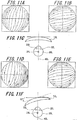
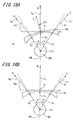
- FIG. 1A shows the line-of-sight direction in the arrangement state assumed in optical design in step S10, i.e., the line-of-sight direction in a state where a lens front angle is provided to a spectacle lens 20 having a lens shape obtained after performing dioptric power correcting process.
- FIG. 1B shows the line-of-sight direction in the arrangement state assumed in optical design in step S3, i.e., the line-of-sight direction in a state where no lens front angle is provided to a spectacle lens 10 of initial lens shape.
- the spectacle lens 20 shown in FIG. 1A is obtained by correcting the lens back surface of the lens 10 shown in FIG. 1B by the method of the present invention so as to improve the prismatic effect.
- FIGS. 1A, 1B , 2A, 2B, 2C, 2D, 2E, 2F , 4A, 4B, 4C, 4D, 4E, 4F , 8A, 8B , 9A, 9B, 9C, 9D, 9E, 9F , 11A, 11B, 11C, 11D, 11E, and 11F each show the line-of-sight direction of the spectacle lens for the left eye; however, since the spectacle lens for the right eye has a configuration bilaterally symmetrical to the spectacle lens for the left eye and therefore has the same function effect as the spectacle lens for the left eye, illustration of the spectacle lens for the right eye will be omitted.
- a left spectacle lens 10L is arranged based on an assumption in optical design so that a fitting point P L on the lens front surface of the left spectacle lens 10L is situated in a reference front line-of-sight 40L passing through a rotation center 31L of the eye; and at the same time, in a horizontal cross section passing through the fitting point P L , a normal line N of the lens front surface at the fitting point P L is identical to the reference front line-of-sight 40L.
- the distance between the lens and the eye at this time is set so that the distance between the lens back surface and the rotation center 31L in the reference front line-of-sight 40L becomes a predetermined value.
- a left spectacle lens 20L is arranged based on an assumption in optical design so that a fitting point P L on the lens front surface of the left spectacle lens 20L is situated in the reference front line-of-sight 40L passing through the rotation center 31L of the eye; and at the same time, in the horizontal cross section passing through the fitting point P L , the normal line N of the lens front surface at the fitting point P L intersects with the reference front line-of-sight 40L at a lens front angle ⁇ LF .
- arrows A L , B L and C L represent the line-of-sights of the left eye 30L
- arrows A Le , B Le and C Le represent image side line-of-sights (i.e., the line-of-sights extending from the rotation center 31L of the eye to the lens 10L) of the respective line-of-sights
- arrows A Le , B Lo and C Lo represent object side line-of--sights (i.e., the line-of-sights extending from the lens 10L to the outside) of the respective line-of-sights.
- object side line-of--sights i.e., the line-of-sights extending from the lens 10L to the outside
- arrows A L ', B L ' and C L ' represent the line-of-sights of the left eye 30L
- arrows A Le ', B Le ' and C Le ' represent image side line-of-sights (i.e., the line-of-sights extending from the rotation center 31L of the eye to the lens 20L) of the respective line-of-sights
- arrows A Lo ', B Lo ' and C Lo ' represent object side line-of-sights (i.e., the line-of-sights extending from the lens 20L to the outside) of the respective line-of-sights.
- the image side line-of-sights B Le and B Le ' when viewing objects in front view are identical to the reference front line-of-sight 40L, the image side line-of-sights A Le and A Le ' are tilted toward the left side by an angle of ⁇ degrees with respect to the reference front line-of-sight 40L, and the image side line-of-sights C Le and C Le ' are tilted toward the right side by an angle of ⁇ degrees with respect to the reference front line-of-sight 40L.
- the prismatic effect of the spectacle lens 20 of the present embodiment shown in FIG. 1A undergone by the ray passing through the rotation center 31 of the eyeball 30 becomes equal to the prismatic effect of the lens, which has the initial lens shape in a state where lens front angle is not provided, shown in FIG. 1B undergone by the line-of-sight passing through the rotation center 31 of the eyeball 30, if the ray shown in FIG. 1A and the ray shown in FIG. 1B have the same line-of-sight direction.
- FIG. 1A shows the prismatic effect of the spectacle lens 20 of the present embodiment shown in FIG. 1A undergone by the ray passing through the rotation center 31 of the eyeball 30 if the ray shown in FIG. 1A and the ray shown in FIG. 1B have the same line-of-sight direction.
- the back surface of the lens 20 is corrected so that the line-of-sight directions of the left-direction line-of-sight A L ', the front-direction line-of-sight B L ' and the right-direction line-of-sight C L ' of the eye 30 on the outside of the lens 20 are substantially equal to the line-of-sight directions of the left-direction line-of-sight A L , the front-direction line-of-sight B L and the right-direction line-of-sight C L on the outside of the lens 10L shown in FIG. 1B .
- Such correction is performed by adding a rotationally asymmetric aspherical element to the lens surface facing the eye,
- the position of the object side line-of-sight B Lo ' of the line-of-sight (front line-of-sight) B L ' is shifted from the position of the object side line-of-sight B Lo of the line-of-sight B L shown in FIG. 1B , but the direction of the object side line-of-sight B Lo ' of the line-of-sight B L ' is identical to the direction of the object side line-of-sight B Lo of the line-of-sight B L .
- angle ⁇ a ' the angle between the image side line-of-sight A Le ' and the object side line-of-sight A Lo ' of the line-of-sight A L ' shown in FIG. 1A
- angle ⁇ a ' the angle between the image side line-of-sight A Le and the object side line-of-sight
- a Lo of the line-of-sight A L shown in FIG. 1B is defined as angle ⁇ a
- the angle ⁇ a ' will be substantially equal to the angle ⁇ a .
- angle ⁇ c ' the angle between the image side line-of-sight C Le and the object side line-of-sight C Lo of the line-of-sight C L shown in FIG. 1B is defined as angle ⁇ c
- angle ⁇ c ' the angle between the image side line-of-sight C Le and the object side line-of-sight C Lo of the line-of-sight C L shown in FIG. 1B
- angle ⁇ c ' will be substantially equal to the angle ⁇ c .
- the directions of the object side line-of-sights A Lo ', C Lo ' shown in FIG. 1A are respectively identical to the directions of the object side line-of-sights A L ⁇ , C Lo shown in FIG. 1B .
- the deviation amount removal rate is set to a value smaller than 100%, if the deviation amount removal rate is smaller, the angle ⁇ a ' on the ear side will become smaller and consequently the difference between the angle ⁇ a ' and angle ⁇ a will be increased, while the angle ⁇ c ' on the nose side will become larger and consequently the difference between the angle ⁇ c ' and angle ⁇ c will be increased.
- the lens is a plus lens
- the object side line-of-sight A Lo ' will be more tilted toward the ear side and consequently the direction of the object side line-of-sight A Lo ' will be closer to the direction of the image side line-of-sight A Le '
- the object side line-of-sight C Lo ' will be more tiltes toward the ear side and consequently the direction of the object side line-of-sight C Lo ' will be farther away from the direction of the image side line-of-sight C Le '.
- the case of a plus lens will be discussed later.
- the first evaluation example is an example of creating the lens shape data of a single-vision lens by the aforesaid method, wherein data of the single-vision lens is: refractive index of the lens material is 1.5, base curve (referred to as "BC” hereinafter) is 8.50D, spherical power (referred to as “S” hereinafter) is +4.00D, center thickness (referred to as "CT” hereinafter) is 8 mm, and prismatic power is 0 ⁇ (however, in the present example, both surfaces of the initial lens shape are spherical surfaces, and the lens back surface is formed into an aspherical surface by the method of the present invention).
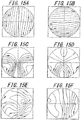
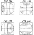
- FIGS. 2A and 2B are each a contour map showing the prismatic effect distribution of the lens 10L of initial lens shape shown in FIG. 2C in the case where there is no lens front angle.
- the contour maps for expressing the prismatic effect distribution shown in the description of the present invention is expressed as coordinates (referred to as "reference spherical coordinates" hereinafter) obtained by projecting the coordinates on a sphere onto a plane perpendicular to the reference front line-of-sight, wherein the center of the sphere is the rotation center, and the radius of the sphere is the distance between the vertex of the surface of the lens facing the eye and the rotation center (expression area is within a circle having a diameter of 40 mm.
- FIGS. 2D, 2E , 3A, 3B , 4A, 4B, 4D, 4E , 5A, 5B , 9A, 9B, 9D, 9E , 10A, 10B , 11A, 11B, 11D, 11E , 12A, 12B , 14A, 14B, 14C, 14D , 15A, 15B , 16A, 16B, 16C, 16D , 17A, 17B , 19A, 19B, 19C, 19D , 20A, 20B , 21A, 21B , 27A and 27B are also contour maps similar to FIGS. 2A and 2B . Incidentally, FIGS.
- FIGS. 1A, 2B, 2D, 2E , 3A, 3B , 4A, 4B, 4D, 4E , 5A, 5B , 9A, 9B, 9D, 9E , 10A, 10B , 11A, 11B, 11D, 11E , 12A, 12B , 19A, 19B, 19C, 19D , 20A, 20B , 21A, 21B , 27A and 27B are coordinates obtained by projecting the left spectacle lens from the back surface, so that the right side is the nose side, and the left side is the ear side. Further, FIGS.
- FIG. 2A shows the prismatic effect in horizontal direction undergone by the ray passing through the rotation center
- FIG. 2B shows the prismatic effect in vertical direction undergone by the ray passing through the rotation center. It can be known that both the prismatic effect in horizontal direction and the prismatic effect in vertical direction are contour lines with substantially the same interval.
- FIG. 2D and 2E are each a contour map showing a prismatic effect distribution in the case where the lens 10L of initial lens shape shown in FIGS. 2A to 2C is simply tilted by 15 degrees in the horizontal direction with the fitting point as a center (i.e., in the case where the lens front angle is set to 15 degrees) as shown in FIG. 2F; and FIG. 2D and 2E are each expressed as the reference spherical coordinates.
- FIG. 2D shows the prismatic effect in horizontal direction undergone by the ray passing through the rotation center
- FIG. 2E shows the prismatic effect in vertical direction undergone by the ray passing through the rotation center.
- the prismatic effect in vertical direction shown in FIG. 2E has no large difference from the case shown in FIG. 2B ; however, in the prismatic effect in horizontal direction shown in FIG. 2D , since the lens 10 is tilted, the interval of the contour lines, particularly the interval of the contour lines in the peripheral portion, becomes uneven, and therefore the prism balance is lost.
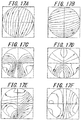
- FIGS. 3A to 3F optical performance evaluation results of a lens obtained by correcting the shape of the lens back surface from the initial lens shape by using the lens shape data creating method of the present invention are shown in FIGS. 3A to 3F , wherein FIG. 3A shows the prismatic effect in horizontal direction undergone by a ray passing through the rotation center, FIG. 3B shows the prismatic effect in vertical direction undergone by the ray passing through the rotation center, FIG, 3C shows the surface astigmatism of the lens front surface, FIG. 3D shows the surface mean power of the lens front surface, FIG. 3E shows the surface astigmatism of the lens back surface, and FIG. 3F shows the surface mean power of the lens back surface.
- FIGS. 3C, 3D , 5C, 5D , 10C, 10D , 12C, 12D , 20C, 20D, 20F , 21C, 21D and 21F are coordinates obtained by projecting the left spectacle lens from the back surface, so that the right side is the nose side, and the left side is the ear side. Further, FIGS.
- 14A, 14B, 14C 14D , 3E, 3F , 5E, 5F , 10E, 10F , 12E, 12F , 15C, 15D , 15F , 17C, 17B, 17C, 17D, 17E and 17F are coordinates obtained by projecting the left spectacle lens from the front surface, so that the right side is the ear side, and the left side is the nose side. Further, the center of the coordinates expressing the surface astigmatism and the surface mean power is either the fitting point in the case where the lens is a single-vision lens, or the prism reference point in the case where the lens is a progressive addition lens.
- the astigmatism and the mean power error can not be sufficiently controlled; however, as shown in FIG. 3A , the distribution bias of the prismatic effect in horizontal direction in the peripheral portion can be substantially removed, and therefore prism balance substantially identical to the prismatic effect in horizontal direction shown in FIG. 2A can be obtained. Further, as shown in FIG. 3F , the interval of the contour lines on the right side (the ear side) from the fitting point is smaller than that on the left side (the nose side), so that the surface mean power of the lens back surface in the horizontal cross section passing through the fitting point changes more largely on the ear side than on the nose side.
- the prismatic effect undergone via the lens by the ray in each line-of-sight direction becomes the same as a lens of initial lens shape.
- the distribution bias of the prismatic power is removed, the problems mentioned above can be improved.
- the wearer of a pair of spectacles mounted with such lenses can obtain a vision with no feeling of discomfort.
- the process of forming the lens back surface into an aspherical surface by the aforesaid prismatic effect correcting steps is performed on the whole lens within the effective angle of view of the lens; however, such process may also be performed on a part of area depending on the intended use. For example, such process may be performed on a part of area on both the left and right sides. Particularly, it is preferred that such process is at least performed on the outer side area (i.e., the ear side area) where the deviation of the line-of-sight direction is serious.
- a spectacle lens with further less feeling of discomfort: increasing the base curve, when creating the initial lens shape data, so that the base curve becomes deeper than the curve typically set with respect to the prescription power; correcting the relative positions and directions of the lens front surface and the lens back surface (step S5) so that the prismatic effect in front-view direction is identical to the prismatic effect in the case where there is no lens front angle; correcting the lens back surface (step S10) so that the prescription power at the power measurement positions can be kept even in the case where a lens front angle is provided; and performing correction to reduce the mean power error and the astigmatism (particularly in the area near the front view direction) increased due to performing the prismatic effect correcting steps.
- the spectacles configured by mounting the spectacle lens corrected in the above manner to a spectacle frame having a large front angle has a shape capable of covering the area surrounding the eyes (particularly the area on the outer sides of the eyes) as well as having a good vision, it is possible to provide a pair of prescription spectacles capable of keeping dust and wind out from the eyes and yet having excellent field of view.
- Second evaluation example an example of a single-vision lens whose prescription power includes cylindrical power
- the second evaluation example is an example of creating the lens shape data of a single-vision lens by the aforesaid method, wherein data of the single-vision lens is: refractive index of the lens material is 1.5, BC is 8.500, S is +4.00D, cylindrical power (referred to as “C” hereinafter) is -2.00D, cylinder axis (referred to as "AX” hereinafter) is 45 degrees, CT is 8 mm, and prismatic power is 0 ⁇ (however, in the present example, the front surface of initial lens shape is a spherical surface, the back surface of initial lens shape is a toroidal surface, and the lens back surface is formed into an atoroidal surface by the method of the present invention).
- FIGS. 4A and 4B are each a contour map showing the prismatic effect distribution of a lens 11L of initial lens shape shown in FIG. 4C in the case where there is no lens front angle; and FIGS. 4A and 4B are each expressed as the reference spherical coordinates.
- FIG. 4A shows a prismatic effect in horizontal direction undergone by a ray passing through the rotation center
- FIG. 4B shows a prismatic effect in vertical direction undergone by the ray passing through the rotation center
- FIG. 4D and 4E are each a contour map showing a prismatic effect distribution in the case where the lens 11L of initial lens shape shown in FIGS. 4A to 4C is simply tilted by 15 degrees in horizontal direction with the fitting point as a center (i.e., in the case where the lens front angle is set to 15 degrees) as shown in FIG. 4F; and FIG. 4D and 4E are each expressed as the reference spherical coordinates.
- FIG. 4D shows the prism effect in horizontal direction undergone by a ray passing through the rotation center
- FIG. 4E shows the prism effect in vertical direction undergone by the ray passing through the rotation center.
- FIGS. 5A to 5F optical performance evaluation results of a lens obtained by correcting the shape of the lens back surface from the initial lens shape using the lens shape data creating method of the present invention are shown in FIGS. 5A to 5F , wherein FIG. 5A shows the prismatic effect in horizontal direction undergone by a ray passing through the rotation center, FIG. 5B shows the prismatic effect in vertical direction undergone by the ray passing through the rotation center, FIG. 5C shows the surface astigmatism of the lens front surface, FIG. 5D shows the surface mean power of the lens front surface, FIG. 5E shows the surface astigmatism of the lens back surface, and FIG. 5F shows the surface mean power of the lens back surface.
- the astigmatism and the mean power error can not be sufficiently controlled; however, the distribution bias of prismatic effect in horizontal direction is significantly reduced, and therefore it is possible to obtain a prismatic effect substantially identical to the optical performance shown in FIGS. 4A and 4B , where the lens is not tilted.
- the interval of the contour lines on the right side (the ear side) from the fitting point is smaller than that on the left side (the nose side), so that the surface mean power of the lens back surface in the horizontal cross section passing through the fitting point changes more largely on the ear side from the fitting point than on the nose side.
- the bias of the prism balance is removed by forming the lens back surface into an atoroidal surface, even if the spectacle lens includes cylindrical power such as lens in the second evaluation example.
- the spectacles configured by mounting such lenses to a frame having a large front angle it is possible to obtain the same advantages as those obtained by the spectacles configured by using the lenses of the first evaluation example, in which the line-of-sight direction passing through the peripheral vision of the left lens and the line-of-sight direction passing through the peripheral vision of the right lens can be made substantially identical to each other, and therefore the discomfort felt by the wearer can be reduced.
- a second embodiment shows an example in which the shape data of a single-vision spectacle lens is created by a method of correcting the distortion resulting from the lens front angle when viewing objects in front view to create the lens shape data.
- a lens shape data creating device to which a lens shape data creating method according to a second embodiment is suitable to be applied, differs from the lens shape data creating device 100, which has been described above with reference to FIG. 6 , in that the processing method of the target prism distribution calculation processing section 132, the processing method of the corrected prism distribution calculation processing section 135 and the processing method of the lens shape correction processing section 137 based on the deviation amount are different, and these differences will be discussed later when describing the lens shape data creating method. However, the description of the like components and configurations will be omitted.
- FIG. 13 is a flowchart for explaining the method of creating the lens shape data of the spectacle lens according to the second embodiment. Similar to the first embodiment, the method of creating the lens shape data of the spectacle lens includes initial lens shape data creating steps (steps S101 and S102) for acquiring data necessary to create the initial lens shape data, and lens back surface shape data correcting steps (steps S103 to S110) for correcting the lens back surface shape data of the created initial lens shape data.
- the lens back surface shape data correcting steps include prismatic effect correcting steps (steps S103 to S109) for performing correction based on the prismatic effect undergone via the lens by the ray passing through the center of the entrance pupil assumed in optical design, and a dioptric power correcting step (step S110) for performing correction based on the dioptric power of the light acting on the eyes in a line-of-sight passing through the eyeball rotation center assumed in optical design and the power measurement position.
- steps S101 and S102 are identical to steps S1 and S2 of the first embodiment, the description thereof will be omitted.
- the description is made based on a case where the initial lens shape data is: the front surface is a spherical surface, and the back surface is a spherical surface or toroidal surface.
- the target prism distribution calculation processing section 132 calculates the prismatic effect undergone by the ray entering the eye and passing through the center of the entrance pupil when viewing objects in front view for each point of the lens, in a state where there is no lens front angle (step S103).
- a state where a lens of the initial shape is arranged at a predetermined distance ahead of the eye without lens front angle is assumed in optical design so that the fitting point of the lens is situated in a reference front line-of-sight of the eye assumed in optical design (an example of the arrangement state of the eyeball and the lens assumed in optical design by step S103 is shown in FIG. 8B ).
- the distance between the lens and the eye at this time may be set so that the distance between the lens back surface and the rotation center in the reference front line-of-sight becomes a predetermined value.
- the prismatic effect undergone via the lens of initial lens shape by a plurality of rays passing through the center of the entrance pupil when viewing objects in the front view direction is calculated, wherein the plurality of rays include the ray in the front view direction.
- the values of the obtained prismatic effect at all points of the lens are regarded as a target prism distribution (a).
- the front angle setting processing section 131 sets a lens front angle with respect to the obtained lens initial shape (step S104). Since the details of setting the front angle are identical to those of the first embodiment, the description thereof will be omitted.
- the prismatic effect correction processing section 133 performs correction of the shape data of the lens back surface in a state where the lens of initial lens shape has a lens front angle, based on the prismatic effect undergone by the front line-of-sight (step S105).
- step S105 the direction of the lens back surface relative to the lens front surface is corrected (referred to as "direction correcting step” hereinafter) so that the prismatic effect undergone via the lens by the ray in front-view direction passing through the center of the entrance pupil when viewing objects in front view in the arrangement state assumed in optical design in step S104 is identical to the prismatic effect undergone via the lens by the ray in front-view direction passing through the center of the entrance pupil when viewing objects in front view in the arrangement state assumed in optical design in step S103.
- step S105 is substantially identical to step S5 of the first embodiment.
- the corrected prism distribution calculation processing section 135 calculates the prismatic effect in a state where there is lens front angle, with respect to the lens shape obtained after performing the direction correcting step in step S105 (step S106).
- the prismatic effect undergone via the lens by one or more rays passing through the center of the entrance pupil when viewing objects in front view is calculated for each point of the lens, wherein the one or more rays exclude the ray in front-view direction.
- the obtained values become a corrected prismatic effect distribution (b).
- the deviation amount calculation processing section 134 calculates the deviation amount of the prismatic effect of the corrected prismatic effect distribution (b) obtained in step S106 with respect to the target prismatic effect distribution (a) obtained in step S103 for each pair of image side line-of-sights in the same direction.
- the deviation amount determination processing section 136 determines whether the deviation amount obtained in step S107 is within an allowed range (step S108). The determination of the deviation amount is performed by determining whether the deviation amount of each point is within a preset allowed range. Incidentally, the allowed range may also be changed according to the area of the lens.
- the lens shape correction processing section 137 will correct the lens shape of the back surface based on the deviation amount (step S109).
- the correction is performed by forming the lens back surface into an aspherical shape or an atoroidal shape.
- step S106 the corrected prism distribution calculation processing section 135 calculates the corrected prismatic effect distribution with respect to the lens shape corrected in step S109.
- the prismatic effect is calculated in the arrangement state assumed in optical design by step S5
- the prismatic effect undergone via the lens by one or more rays passing through the center of the entrance pupil when viewing objects in front view is calculated for each point of the lens in the arrangement state assumed in optical design by step S9, wherein the one or more rays exclude the ray in front-view direction.
- the deviation amount calculation processing section 134 calculates the difference between the target prismatic effect distribution (a) and the corrected prismatic effect distribution (b) re-calculated in step S106 after being corrected in step S109 to make determination.
- steps S106 to S109 form a loop to be repeatedly executed until the deviation amount with respect to the target prismatic effect becomes within the allowed range. Further, when determining that the deviation amount is within the allowed range, the deviation amount determination processing section 136 ends the prismatic effect correction, so that the design shape of a lens having corrected distortion when viewing objects in front view can be obtained.
- lens shape data having the shape data of the lens back surface corrected after the direction correcting step can be obtained so that the prismatic effect undergone via the lens of the lens shape after direction correcting step by one or more rays passing through the center of the entrance pupil when viewing objects in front view assumed in optical design in a. state where there is lens front angle is identical or close to the prismatic effect undergone via the lens of initial lens shape by the one or more rays passing through the center of the entrance pupil when viewing objects in front view assumed in optical design in a state where there is no lens front angle, wherein the one or more rays exclude the ray in the front view direction.
- the prismatic effect correction is mainly performed on the prismatic effect in horizontal direction undergone via the lens by the ray passing through the eyeball rotation center.
- the power correction processing section 141 corrects the shape data of the lens back surface so that, in a state where there is lens front angle, the dioptric power of the light acting on the eyes in a line-of-sight passing through the eyeball rotation center assumed in optical design and the power measurement position is identical to the prescription value (step S110). Since this step is identical to step S10 of the first embodiment, the description thereof will be omitted.
- the shape data of the spectacle lens of the second embodiment can be created by performing the above arithmetic processing.
- the spectacle lens of the present invention is produced based on the created lens shape data. Further, a pair of spectacles can be obtained by edging the spectacle lenses produced by the method of the present invention and fitting the edged lenses into a spectacle frame. Since these method and device are identical to those of the first embodiment, the description thereof will be omitted.
- the lens shape data created by the above method will be described below in further details.
- the prismatic effect (particularly the prismatic effect in horizontal direction) mainly with respect to the fixation line is corrected; while in the lens shape according to the second embodiment, as described above, the distortion is corrected in a case where the fixation line is in the front direction, and in such case, the correction is performed considering the ray passing through the center of the entrance pupil of the eyeball optical system.
- FIG. 8A shows the line-of-sight direction in the arrangement state assumed in optical design in step S110 (i.e., in the state where a lens front angle is provided to a spectacle lens 22 of the lens shape obtained after performing dioptric power correcting process).
- FIG. 8B shows the line-of-sight direction in the arrangement state assumed in optical design in step S103 (i.e., in a state where no lens front angle is provided to a spectacle lens 12 of initial lens shape).
- the spectacle lens 22 shown in FIG. 8A is obtained by correcting the lens back surface of the lens 12 shown in FIG. 8B by the method of the present invention, so as to reduce the distortion.
- a left spectacle lens 12L is arranged based on an assumption in optical design so that a fitting point P L on the lens front surface of the left spectacle lens 12L is situated in a reference front line-of-sight 40L passing through a rotation center 31L of the eye, and so that, in a horizontal cross section passing through the fitting point P L , a normal line N of the lens front surface at the fitting point P L is identical to the reference front line-of-sight 40L.
- the distance between the lens and the eye at this time is set so that the distance between the lens back surface and the rotation center 31L in the reference front line-of-sight 40L becomes a predetermined value.
- a left spectacle lens 22L is arranged based on an assumption in optical design so that a fitting point P L on the lens front surface of the left spectacle lens 22L is located in the reference front line-of-sight 40L passing through the rotation center 31L of the eye; and at the same time, in the horizontal cross section passing through the fitting point P L , the normal line N of the lens front surface at the fitting point P L intersects with the reference front line-of-sight 40L at a lens front angle ⁇ LF .
- arrows D L , E L and F L represent the line-of-sights of the left eye 30L
- arrows D Le , E Le and F Le represent image side line-of-sights of the respective line-of-sights
- arrows D Lo , E Lo and F Lo represent object side line-of-sights of the respective line-of-sights.
- arrows D L ', E L ' and F L ' represent the line-of-sights of the left eye 30L
- arrows D Le ', E Le ' and F Le ' represent image side line-of-sights of the respective line-of-sights
- arrows D Lo ', E Lo ' and F Lo ' represent object side lino-of-sights of the respective line-of-sights.
- the image side line-of-sights E Le and E Le ' when viewing objects in front view are identical to the reference front line-of-sight 40L, the image side line-of-sights D Le and D Le ' are tilted toward the left side by an angle of ⁇ degrees with respect to the reference front line-of-sight 40L, and the image side line-of-sights F Le and F Le are tilted toward the right side by an angle of ⁇ degrees with respect to the reference front line-of-sight 40L.
- the prismatic effect undergone by each ray passing through the center of the entrance pupil 32 of the eyeball 30 when viewing objects in front view becomes equal to the prismatic effect of the lens of initial lens shape shown in FIG. 8B undergone by each ray passing through the center of the entrance pupil 32 of the eyeball 30 when viewing objects in front view, in a state where lens front angle is not provided.
- the prismatic effect undergone by each ray passing through the center of the entrance pupil 32 of the eyeball 30 when viewing objects in front view becomes equal to the prismatic effect of the lens of initial lens shape shown in FIG. 8B undergone by each ray passing through the center of the entrance pupil 32 of the eyeball 30 when viewing objects in front view, in a state where lens front angle is not provided.
- the back surface of the lens 22 is corrected so that the line-of-sight directions of the left-direction line-of-sight D L ', the front-direction line-of-sight E L ' and the right-direction line-of-sight F L ' of the eye 30 on the outside of the lens 22 are substantially equal to the line-of-sight directions of the left-direction line-of-sight D L , the front-direction line-of-sight E L and the right-direction line-of-sight F L on the outside of the lens 12L shown in FIG. 1B .
- Such correction is performed by adding a rotationally asymmetric aspherical element to the lens surface facing the eye.
- the position of the object side line-of-sight E Lo ' of the line-of-sight (front line-of-sight) E L ' is shifted from the position of the object side line-of-sight E Lo of the line-of-sight E L shown in FIG. 8B , but the direction of the object side line-of-sight E Lo ' of the line-of-sight E L ' is identical to the direction of the object side line-of-sight E L ⁇ of the line-of-sight E L .
- angle ⁇ d ' the angle between the image side line-of-sight D Le ' and the object side line-of-sight D Lo ' of the line-of-sight D L ' shown in FIG. 8A
- angle ⁇ d ' the angle between the image side line-of-sight D Le and the object side line-of-sight D Lo of the line-of-sight D L shown in FIG. 1B
- angle ⁇ d ' will be substantially equal to the angle ⁇ d .
- angle ⁇ d ' the angle between the image side line-of-sight F Le ' and the object side line-of-sight F Lo ' of the line-of-sight F L ' shown in FIG.
- angle ⁇ f ' the angle between the image side line-of-sight F Le and the object side line-of-sight F Lo of the line-of-sight F L shown in FIG. 8B is defined as angle ⁇ f
- the angle ⁇ f ' will be substantially equal to the angle ⁇ f
- the directions of the object side line-of-sights D Lo ', F Lo ' shown in FIG. 8A are respectively identical to the directions of the object side line-of-sights D Lo , F Lo shown in FIG. 8B .
- the first evaluation example is an example of creating the lens shape data of a single-vision lens by the aforesaid method, wherein data of the single-vision lens is: refractive index of the lens material is 1.5, BC is 8.50D, S is +4.00D, CT is 8 mm, and prismatic power is 0 ⁇ (however, in the present example, both surfaces of initial lens shape are spherical surfaces, and the lens back surface is formed into an aspherical surface by the method of the present invention).
- FIGS. 9A and 9B are each a contour map showing the prismatic effect distribution of the lens 12L of initial lens shape shown in FIG. 9C in the case where there is no lens front angle; and FIGS. 9A and 9B are expressed as coordinates obtained by projecting the coordinates on a sphere onto a plane perpendicular to the reference front line-of-sight, wherein the center of the sphere is the center of the entrance pupil when viewing objects in front view, and the radius of the sphere is the distance between the vertex of the surface of the lens facing the eye and the center of the entrance pupil (expression area is within a circle having a diameter of 30 mm.
- FIGS. 9A and 9B are each a contour map showing the prismatic effect distribution of the lens 12L of initial lens shape shown in FIG. 9C in the case where there is no lens front angle; and FIGS. 9A and 9B are expressed as coordinates obtained by projecting the coordinates on a sphere onto a plane perpendicular to the reference front line-of-sight, where
- FIG. 9D, 9E , 10A, 10B , 11A, 11B, 11D, 11E , 12A and 12B are also contour maps similar to FIGS. 9A and 9B).
- FIG. 9A shows the prismatic effect in horizontal direction undergone by a ray passing through the center of the entrance pupil
- FIG. 9B shows the prismatic effect in vertical direction undergone by the ray passing through the center of the entrance pupil. It can be known that both the prismatic effect in horizontal direction and the prismatic effect in vertical direction are contour lines with substantially the same interval.
- FIG. 9D and 9E are each a contour map showing the distribution of the prismatic effect with respect to the ray passing through the center of the entrance pupil 32 in the case where the lens 12L of initial lens shape shown in FIGS. 9A to 9C is simply tilted by 15 degrees in the horizontal direction with the fitting point as a center (i.e., in the case where the lens front angle is set to 15 degrees) as shown in FIG. 9F; and FIG. 9D and 9E are each expressed as the aforesaid coordinates.
- FIG. 9D shows the prismatic effect in horizontal direction undergone by a ray passing through the center of the entrance pupil
- FIG. 9E shows the prismatic effect in vertical direction undergone by the ray passing through the center of the entrance pupil. It is known that, since the lens 12 is tilted, large bias of the distribution of the prismatic effect in horizontal direction shown in FIG. 9D is caused in the peripheral portion.
- FIGS. 10A to 10F optical performance evaluation results of a lens obtained by correcting the shape of the lens back surface from the initial lens shape by the lens shape data creating method of the present invention are shown in FIGS. 10A to 10F , wherein FIG. 10A shows the prismatic effect in horizontal direction undergone by the ray passing through the center of the entrance pupil, FIG. 10B shows the prismatic effect in vertical direction undergone by the ray passing through the center of the entrance pupil, FIG. 10C shows the surface astigmatism of the lens front surface, FIG. 10D shows the surface mean power of the lens front surface, FIG. 10E shows the surface astigmatism of the lens back surface, and FIG. 10F shows the surface mean power of the lens back surface.
- FIGS. 10A shows the prismatic effect in horizontal direction undergone by the ray passing through the center of the entrance pupil
- FIG. 10B shows the prismatic effect in vertical direction undergone by the ray passing through the center of the entrance pupil
- FIG. 10C shows the surface astigmatism of the lens front surface
- the prismatic effect distribution of such lens is substantially equal to the prismatic effect distribution shown in FIG. 9A in the case of the lens with no tilt. Further, as shown in FIG.
- the interval of the contour lines on the right side (the ear side) from the fitting point is smaller than that on the left side (the nose side), so that the surface mean power of the lens back surface in the horizontal cross section passing through the fitting point changes more largely on the ear side from the fitting point than on the nose side.
- bias of the prismatic effect with respect to the ray passing through the rotation center of the eyeball i.e., with respect to each ray in the line-of-sight direction
- bias of the prismatic effect undergone via the lens by all rays passing through the center of the entrance pupil when viewing objects in front view is reduced.
- the angle at which each ray from the peripheral vision enters the center of the entrance pupil when viewing objects in front view, or the position of the image formed on the retina can be made equivalent to those of the lens with no tilt shown in FIG. 8B .
- the distortion caused by tilting the lens can be reduced.
- Second evaluation example an example of a single-vision lens whose prescription power includes cylindrical power
- the second evaluation example is an example of creating the lens shape data of a single-vision lens by the aforesaid method, wherein data of the single-vision lens is: refractive index of the lens material is 1.5, BC is 8.50D, S is +4.00D, C is -2.00D, AX is 45 degrees, CT is 8 mm, and prismatic power is 0 ⁇ (however, in the present example, the front surface of initial lens shape is a spherical surface, the back surface of initial lens shape is a toroidal surface, and the lens back surface is formed into an atoroidal surface by the method of the present invention).
- FIGS. 11A and 11B are each a contour map showing the prismatic effect distribution of the lens 13L of initial lens shape shown in FIG. 11C in the case where there is no lens front angle; and FIGS. 11A and 11B are expressed as coordinates obtained by projecting the coordinates on a sphere onto a plane perpendicular to the reference front line-of-sight, wherein the center of the sphere is the center of the entrance pupil when viewing objects in front view, and the radius of the sphere is the distance between the vertex of the surface of the lens facing the eye and the center of the entrance pupil.
- FIG. 11A shows the prismatic effect in horizontal direction undergone by a ray passing through the center of the entrance pupil
- FIG. 11B shows the prismatic effect in vertical direction undergone by the ray passing through the center of the entrance pupil.
- FIG. 11D and 11E are each a contour map expressing a prism effect distribution in a case where the lens 13L of initial lens shape shown in FIGS. 11A to 11C is simply tilted by 15 degrees in the horizontal direction with the fitting point as a center as shown in FIG. 11F (i.e., in a case where the lens front angle is set to 15 degrees); and FIG. 11D and 11E are each expressed as the aforesaid coordinates.
- FIG. 11D shows the prismatic effect in horizontal direction undergone by a ray passing through the center of the entrance pupil
- FIG. 11E shows the prismatic effect in vertical direction undergone by the ray passing through the center of the entrance pupil. Since the lens 13 is tilted, bias of the distribution of the prismatic effect in horizontal direction shown in FIG. 11D is caused in the peripheral portion. Thus, the distortion resulting from the lens front angle is generated in the peripheral vision area when viewing objects in front view.
- FIG. 12B is a contour map of the prismatic effect in vertical direction undergone by the ray passing through the center of the entrance pupil
- FIG. 12F is a contour map of the surface mean power of the lens back surface.
- FIGS. 12A and 12B are each expressed as the aforesaid coordinates.
- the astigmatism and the mean power error can not be sufficiently controlled; however, as shown in FIG. 12A , the bias of the prism balance, particularly the bias of the prism in horizontal direction, in the peripheral portion can be almost removed, and therefore the prismatic effect distribution can be made substantially equal to the prismatic effect distribution shown in FIG. 11A where the lens 13 is not tilted. Further, as shown in FIG.
- the interval of the contour lines on the right side (the ear side) from the fitting point is smaller than that on the left side (the nose side), so that the surface mean power of the lens back surface in the horizontal cross section passing through the fitting point changes more largely on the ear side from the fitting point than on the nose side.
- the lens back surface i.e., the concave surface facing the eyeball
- bias of the distribution of the prismatic effect undergone via the lens by each ray passing through the center of the entrance pupil of the eyeball when viewing objects in front view is removed.
- the distortion caused by tilting the lens, particularly in the peripheral portion when viewing objects in front view can be corrected.
- the third embodiment is an example of creating the shape data of a progressive addition lens by a method identical to the method of the first embodiment.
- the present embodiment is described based on a case where the shape data of a progressive addition lens is created, wherein the front surface of the progressive addition lens is a progressive-addition surface, and the back surface of the progressive addition lens is an aspherical or atoroidal surface.
- the lens shape data creating device 100 having been described above with reference to FIG. 6 may be used as a lens shape data creating device, to which a lens shape data creating method according to the third embodiment is suitable to be applied. Also, since the method of creating the lens shape data using such a lens shape data creating device can be performed following the flowchart of FIG. 7 , the part different from the method of the first embodiment will be described later when describing the lens shape data creating method, and the description of the part identical to the method of the first embodiment will be omitted.
- steps S1 and S2 are identical to those of the first embodiment except that, in the created initial lens shape data, the front surface is a progressive-addition surface, and the back surface is a spherical surface or toroidal surface. Since the prismatic effect correcting steps (steps S3 to S9) are identical to those of the first embodiment, the description thereof will be omitted.
- the dioptric power correcting step (step S10) is identical to that of the first embodiment except that the power measurement position is the distance-portion measuring reference point.
- the shape data of the spectacle lens of the third embodiment can be created by performing the above arithmetic processing.
- the progressive addition spectacle lens of the present invention is produced based on the created lens shape data. Further, a pair of spectacles can be obtained by edging the progressive addition spectacle lenses produced by the method of the present invention and fitting the edged lenses into a spectacle frame. Since these method and device are identical to those of the first embodiment, the description thereof will be omitted.
- the object side line-of-sights corresponding to the image side line-of-sights of the same direction between the case where there is lens front angle and the case where there is no lens front angle have substantially the same direction.
- the first evaluation example is an example of creating the lens shape data of a progressive addition lens by the aforesaid method, wherein data of the progressive addition lens is: refractive index of the lens material is 1.5, BC is 9.00D, S is +4.00D, addition power (referred to as "ADD" hereinafter) is 2.00D, CT is 8 mm, and prismatic power is 0 ⁇ (however, in the present example, the front surface of initial lens shape is a progressive-addition surface, the back surface of initial lens shape is a spherical surface, and the lens back surface is formed into an aspherical surface by the method of the present invention).
- FIGS. 14A and 14B are each a contour map showing the prismatic effect distribution of the lens of initial lens shape in the case where there is no lens front angle
- FIGS. 4A and 4B are each expressed as the reference spherical coordinates.
- FIG. 14A shows the prismatic effect in horizontal direction undergone by a ray passing through the rotation center
- FIG. 14B shows the prismatic effect in vertical direction undergone by the ray passing through the rotation center.
- Both the prismatic effect in horizontal direction and the prismatic effect in vertical direction are bilaterally symmetrical contour lines with substantially the same interval.
- FIG. 14C and 14D are each a contour map showing a prismatic effect distribution in the case where the lens of initial lens shape shown in FIG. 14A and 14B is simply tilted by 15 degrees in horizontal direction with the fitting point as a center (i.e., in the case where the lens front angle is set to 15 degrees), and 14C and 14D are each expressed as the reference spherical coordinates.
- FIG. 14C shows the prism effect in horizontal direction undergone by a ray passing through the rotation center
- FIG. 14D shows the prism effect in vertical direction undergone by the ray passing through the rotation center.
- the prismatic effect in vertical direction shown in FIG. 14D has no large difference from the case shown in FIG. 14B ; however, as shown in FIG. 14C , since the lens is tilted, the interval of the contour lines of the prismatic effect in horizontal direction becomes uneven particularly in the peripheral portion, and therefore the prism balance is lost.
- FIGS. 15A to 15F optical performance evaluation results of a lens obtained by correcting the shape of the lens back surface from the initial lens shape by the lens shape data creating method of the present invention are shown in FIGS. 15A to 15F , wherein FIG. 15A shows the prismatic effect in horizontal direction undergone by a ray passing through the rotation center, FIG. 15B shows the prismatic effect in vertical direction undergone by the ray passing through the rotation center, FIG. 15C shows the surface astigmatism of the lens front surface, FIG. 15D shows the surface mean power of the lens front surface, FIG. 15E shows the surface astigmatism of the lens back surface, and FIG. 15F shows the surface mean power of the lens back surface.
- the astigmatism and the mean power error can not be sufficiently controlled; however, as shown in FIG. 15A , the distribution bias of the prismatic effect in horizontal direction in the peripheral portion can be substantially removed, and therefore prism balance substantially identical to the prismatic effect in horizontal direction shown in FIG. 14A can be obtained. Further, as shown in FIG. 15F , the interval of the contour lines on the right side (the ear side) from the prism reference point is smaller than that on the left side (the nose side), so that the surface mean power of the lens back surface in the horizontal cross section passing through the prism reference point changes more largely on the ear side from the prism reference point than on the nose side.
- the prismatic effect undergone via the lens by the ray in each line-of-sight direction becomes the same as the lens of initial lens shape.
- the wearer of a pair of spectacles mounted with such lenses can obtain a vision with no feeling of discomfort.
- Second evaluation example an example of correcting a progressive addition lens whose prescription power includes cylindrical power
- the second evaluation example is an example of creating the lens shape data of a progressive addition lens by the aforesaid method, wherein data of the progressive addition lens is refractive index of the lens material is 1.5, BC is 9.00D, S is +4.00D, C is -2.00D, AX is 45 degrees, addition ADD is 2.00D, CT is 8 mm, and prismatic power is 0 ⁇ (however, in the present example, the front surface of initial lens shape is a progressive-addition surface, the back surface of initial lens shape is a toroidal surface, and the lens back surface is formed into an atoroidal surface by the method of the present invention).
- FIGS. 16A and 16B are each a contour map showing the prismatic effect distribution of the lens of initial lens shape in the case where there is no lens front angle
- FIGS. 4A and 4B are each expressed as the reference spherical coordinates.
- FIG. 16A shows the prismatic effect in horizontal direction undergone by a ray passing through the rotation center
- FIG. 16B shows the prismatic effect in vertical direction undergone by the ray passing through the rotation center.
- FIG. 16C and 16D are each a contour map showing a prismatic effect distribution in the case where the lens of initial lens shape shown in FIG. 16A and 16B is simply tilted by 15 degrees in horizontal direction with the fitting point as a center (i.e., in the case where the lens front angle is set to 15 degrees), and 16C and 16D are each expressed as the reference spherical coordinates.
- FIG. 16C shows the prism effect in horizontal direction undergone by a ray passing through the rotation center
- FIG. 16D shows the prism effect in vertical direction undergone by the ray passing through the rotation center.
- the distribution bias of the prismatic effect in horizontal direction is caused in the peripheral portion.
- FIG. 17B is a contour map of the prismatic effect in vertical direction undergone by the ray passing through the rotation center
- FIG. 17C is a contour map of
- 17F is a contour map of the surface mean power of the lens back surface.
- the astigmatism and the mean power error can not be sufficiently controlled; however, as shown in FIG. 17A , the distribution bias of prismatic power in horizontal direction is significantly reduced, and therefore a prismatic effect substantially identical to the optical performance shown in FIG. 16A , where the lens is not tilted, can be obtained. Further, as shown in FIG. 17A , the distribution bias of prismatic power in horizontal direction is significantly reduced, and therefore a prismatic effect substantially identical to the optical performance shown in FIG. 16A , where the lens is not tilted, can be obtained. Further, as shown in FIG.
- the interval of the contour lines on the right side (the ear side) from the prism reference point is smaller than that on the left side (the nose side), so that the surface mean power of the lens back surface in the horizontal cross section passing through the prism reference point changes more largely on the ear side from the prism reference point than on the nose side.
- bias of the prism balance can be removed by forming the lens back surface into an atoroidal surface, even if the spectacle lens is a progressive addition spectacle lens whose prescription power includes cylindrical power.
- a fourth embodiment shows an example in which shape data of a single-vision spectacle lens is created by a method identical to the method of the first embodiment, wherein a lens having its back surface shape corrected for removing the astigmatism and the mean power error felt by the eyes in the state where there is no lens front angle (the back surface of such lens is an atoroidal surface or rotationally symmetric aspherical surface, and, for sake of simplicity, those lenses are collectively called “back surface aspherical lens” hereinafter) is used as the lens of initial lens shape.
- the present embodiment is an example in which the shape data of a single-vision minus lens is created, wherein the single-vision minus lens is a single-vision minus lens whose front surface is a spherical surface, whose back surface is an aspherical surface, and whose prescription power includes no cylindrical power.
- the example is discussed based on two cases, one is the case where the deviation amount removal rate of the prismatic effect is 100%, and another is the case where the deviation amount removal rate of the prismatic effect is 50%.
- the lens shape data creating device 100 having been described above with reference to FIG. 6 may be used as a lens shape data creating device, to which a lens shape data creating method according to the third embodiment is suitable to be applied. Also, since the method of creating the lens shape data using such a lens shape data creating device can be performed following the flowchart of FIG. 7 , the part different from the method of the first embodiment will be described later when describing the lens shape data creating method, and the description of the part identical to the method of the first embodiment will be omitted.
- steps S1 and S2 are identical to those of the first embodiment except that the created initial lens shape data is: the front surface is a spherical surface, and the back surface is a rotationally symmetric aspherical surface whose shape is corrected for removing the astigmatism and the mean power error felt by the eyes in both the front line-of-sight and the area other than front sight in the state where there is no lens front angle.
- the process is identical to that of the first embodiment except that the deviation amount of the corrected prismatic effect distribution (b) firstly calculated in step S6 following step S5 with respect to the target prismatic effect distribution (a) is removed by 100% or 50% in the whole area of the lens.
- the dioptric power correcting step (step S10) is identical to that of the first embodiment.
- the shape data of the spectacle lens of the fourth embodiment can be created by performing the above arithmetic processing.
- the single-vision minus lens of the present invention is produced based on the created lens shape data.
- a pair of spectacles can be obtained by edging the single-vision minus lenses produced by the method of the present invention and fitting the edged lenses into a spectacle frame. Since these method and device are identical to those of the first embodiment, the description thereof will be omitted.
- the lens shape of the fourth embodiment has the prismatic effect (particularly the prismatic effect in horizontal direction) undergone mainly by the fixation line of the eye corrected.
- FIG. 18A shows the line-of-sight direction in the arrangement state assumed in optical design in step S10, i.e., the line-of-sight direction in a state where a lens front angle is provided to a spectacle lens 24 having a lens shape obtained after performing dioptric power correcting process.
- FIG. 1B shows the line-of-sight direction in the arrangement state assumed in optical design in step S3, i.e., the line-of-sight direction in a state where no lens front angle is provided to a spectacle lens 10 of initial lens shape.
- the spectacle lens 24 shown in FIG. 18A is obtained by correcting the lens back surface of the lens 14 shown in FIG. 18B by the method of the present invention so as to improve the prismatic effect.
- a left spectacle lens 14L is arranged based on an assumption in optical design so that a fitting point P L on the lens front surface of the left spectacle lens 14L is situated in a reference front line-of-sight 40L passing through a rotation center 31L of the eye, and so that, in a horizontal cross section passing through the fitting point P L , a normal line N of the lens front surface at the fitting point P L is identical to the reference front line-of-sight 40L.
- the distance between the lens and the eye at this time is set so that the distance between the lens back surface and the rotation center 31L in the reference front line-of-sight 40L becomes a predetermined value.
- a left spectacle lens 24L is arranged based on an assumption of optical design so that a fitting point P L on the lens front surface of the left spectacle lens 24L is located in the reference front line-of-sight 40L passing through the rotation center 31L of the eye, and at the same time, in the horizontal cross section passing through the fitting point P L , the normal line N of the lens front surface at the fitting point P L intersects with the reference front line-of-sight 40L at a lens front angle ⁇ LF .
- arrows G L , H L and I L represent the line-of-sights of the left eye 30L
- arrows G Le , H Le and I Le represent image side line-of-sights of the respective line-of-sights
- arrows G Lo , H Lo and I Lo represent object side line-of-sights of the respective line-of-sights.
- arrows G L ', H L ' and I L ' represent the line-of-sights of the left eye 30L
- arrows G Le ', H Le ' and I Le ' represent image side line-of-sights of the respective line-of-sights
- arrows G Lo ', H Lo ' and I Lo ' represent object side line-of-sights of the respective line-of-sights.
- the image side line-of-sights H Le and H Le ' when viewing objects in front view are identical to the reference front line-of-sight 40L, the image side line-of-sights G Le and G Le ' are tilted toward the left side by an angle of ⁇ degrees with respect to the reference front line-of-sight 40L, and the image side line-of-sights I Le and I Le ' are tilted toward the right side by an angle of ⁇ degrees with respect to the reference front line-of-sight 40L.
- the prismatic effect of the spectacle lens 24 of the fourth embodiment shown in FIG. 18A by correct ing the lens back surface, the prismatic effect undergone by a ray passing through the rotation center 31 of the eyeball 30 is equal or close, in a degree proportional to the deviation amount removal rate, to the prismatic effect of the initial lens shape in a state where lens front angle is not provided shown in FIG. 18B undergone by a ray passing through the rotation center 31 of the eyeball 30, if the ray shown in FIG. 1A and the ray shown in FIG. 1B have the same line-of-sight direction.
- the deviation amount removal rate is 100%, as shown in FIG.
- the back surface of the lens 24 is corrected so that the line-of-sight directions of the left-direction line-of-sight G L ', the front-direction line-of-sight H L ' and the right-direction line-of-sight I L ' of the eye 30 on the outside of the lens 24 are substantially equal to the line-of-sight directions of the left-direction line-of-sight G L , the front-direction line-of-sight H L and the right-direction line-of-sight I L on the outside of the lens 12L shown in FIG. 18B .
- Such correction is performed by adding a rotationally asymmetric aspherical element to the lens surface facing the eye.
- the position of the object side line-of-sight H Lo ' of the line-of-sight (front line-of-sight) H L ' is shifted from the position of the object side line-of-sight H Lo of the line-of-sight H L shown in FIG. 18B , but the direction of the object side line-of-sight H Lo ' of the line-of-sight H L ' is identical to the direction of the object side line-of-sight H Lo of the line-of-sight H L .
- angle ⁇ g ' the angle between the image side line-of-sight G Le ' and the object side line-of-sight G Lo ' of the line-of-sight G L ' shown in FIG. 18A
- angle ⁇ g ' the angle between the image side line-of-sight G Le and the object side line-of-sight D Lo of the line-of-sight G L shown in FIG. 18B
- angle ⁇ g ' will be substantially equal to the angle ⁇ g .
- angle ⁇ g ' the angle between the image side line-of-sight I Le ' and the object side line-of-sight I Lo ' of the line-of-sight I L ' shown in FIG.
- the angle ⁇ g ' on the ear side will become smaller and therefore the difference between the angle ⁇ g ' and angle ⁇ g will be increased, and the angle ⁇ i ' on the nose side will become larger and therefore the difference between the angle ⁇ i ' and angle ⁇ i will be increased.
- the object side line-of-sight G Lo ' will be more tilted toward the nose side and consequently the direction of the object side line-of-sight G Lo ' will be closer to the direction of the image side line-of-sight G Le ', while the object side line-of-sight I Lo ' will be more tilted toward the nose side and consequently the direction of the object side line-of-sight I Lo ' will be farther-away from the direction of the image side line-of-sight I Le '.
- the first evaluation example is an example of creating the lens shape data of a single-vision minus lens by the aforesaid method with a deviation amount removal rate of 100%, wherein data of the single-vision minus lens is: refractive index of the lens material is 1.5, BC is 8.50D, S is -4.00D, CT is 1 mm, and prismatic power is 0 ⁇ .
- FIGS. 19A and 19B are each a contour map showing the prismatic effect distribution of the lens of initial lens shape in the case where there is no lens front angle
- FIGS. 19A and 19B are each expressed as the reference spherical coordinates.
- FIG. 19A shows the prismatic effect in horizontal direction undergone by a ray passing through the rotation center
- FIG. 19B shows the prismatic effect in vertical direction undergone by the ray passing through the rotation center. It can be known that both the prismatic effect in horizontal direction is contour lines with substantially the same interval lined up in left-right direction, and the prismatic effect in vertical direction is contour lines with substantially the same interval lined up in up-down direction.
- FIG. 19C and 19D are each a contour map showing a prismatic effect distribution in the case where the lens of initial lens shape shown in FIG. 19A and 19B is simply tilted by 15 degrees in horizontal direction with the fitting point as a center (i.e., in the case where the lens front angle is set to 15 degrees), and 19C and 19D are each expressed as the reference spherical coordinates.
- FIG. 19C shows the prism effect in horizontal direction undergone by a ray passing through the rotation center
- FIG. 19D shows the prism effect in vertical direction undergone by the ray passing through the rotation center.
- the prismatic effect in vertical direction shown in FIG. 19D has no large difference from the case shown in FIG. 19B ; however, as shown in FIG. 19C , since the lens is tilted, the interval of the contour lines of the prismatic effect in horizontal direction becomes uneven particularly in the peripheral portion, and therefore the prism balance is lost.
- FIGS. 20A to 20F optical performance evaluation results of a lens obtained by correcting the shape of the lens back surface from the initial lens shape by the lens shape data creating method of the present invention are shown in FIGS. 20A to 20F , wherein FIG. 20A shows the prismatic effect in horizontal direction undergone by a ray passing through the rotation center, FIG. 20B shows the prismatic effect in vertical direction undergone by the ray passing through the rotation center, FIG. 20C shows the surface astigmatism of the lens front surface, FIG. 20D shows the surface mean power of the lens front surface, FIG. 20E shows the surface astigmatism of the lens back surface, and FIG. 20F shows the surface mean power of the lens back surface.
- the astigmatism and the mean power error can not be sufficiently controlled; however, as shown in FIG. 20A , the distribution bias of the prismatic effect in horizontal direction in the peripheral portion can be substantially removed, and therefore prism balance substantially identical to the prismatic effect in horizontal direction shown in FIG. 20A can be obtained. Further, as shown in FIG. 20F , the interval of the contour lines on the right side (the ear side) from the fitting point is smaller than that on the left side (the nose side), so that the surface mean power of the lens back surface in the horizontal cross section passing through the fitting point changes more largely on the ear side than on the nose side.
- the prismatic effect undergone via the lens by the ray in each line-of-sight direction becomes the same as the lens of initial lens shape.
- the wearer of a pair of spectacles mounted with such lenses can obtain a vision with no feeling of discomfort.
- the second evaluation example is an example of creating the lens shape data of a single-vision minus lens by the aforesaid method with a deviation amount removal rate of 50%, wherein data of the single-vision minus lens is: refractive index of the lens material is 1.5, BC is 8.50D, S is -4.00D, CT is 1 mm, and prismatic power is 0 ⁇ .
- Contour maps showing the prismatic effect distribution of a lens of initial lens shape in the case where there is no lens front angle and contour maps showing a prismatic effect distribution in the case where the aforesaid lens of initial lens shape is simply tilted by 15 degrees in horizontal direction with the fitting point as a center (i.e., in the case where the lens front angle is set to 15 degrees) are identical to those shown in FIGS. 19A to 19D .
- FIG. 21B is a contour map of the prismatic effect in vertical direction undergone by the ray passing through the rotation center
- FIG. 21C is a contour map of
- 21F is a contour map of the surface mean power of the lens back surface.
- the astigmatism and the mean power error are reduced compared to the first evaluation example; however, as shown in FIG. 21A , the bias of the distribution of the prismatic effect in horizontal direction is increased compared to the first evaluation example.
- the interval of the contour lines on the right side (the ear side) from the fitting point is smaller than that on the left side (the nose side), so that the surface mean power of the lens back surface in the horizontal cross section passing through the fitting point changes more largely on the ear side than on the nose side.
- the increase of the astigmatism and mean power error is suppressed, and the bias of the prism balance is removed to a certain level. In such case, the discomfort felt by the wearer may also be reduced.
- the present invention may also be applied to a case where the lens is a single-surface progressive-addition lens whose back surface is a progressive-addition surface.
- the shape data of the progressive-addition surface of the lens back surface may be corrected by the method of the present invention.
- the present invention may also be applied to multi-focal lens.
- the initial lens shape may be such that the segment is formed on the front surface, and the back surface is a spherical surface or a toroidal surface; and the shape data of the lens back surface may be corrected.
- the distance-portion measuring reference point may be used as the power measurement position.
- first to third embodiments are described based on cases where the corrected surface of initial lens shape is the spherical surface or toroidal surface, the present invention may also be applied to a case where a rotationally symmetric aspherical surface ot atoroidal surface is corrected.
- the fourth embodiment is described based on a case where the corrected surface of initial lens shape is a rotationally symmetric aspherical surface, the present invention may also be applied to a case where an atoroidal surface is corrected.
- first, second and fourth embodiments are described based on cases where the uncorrected surface (the front surface) of initial lens shape is a spherical surface, the present invention may also be applied to a case where the uncorrected surface of initial lens shape is a rotationally symmetric aspherical surface.
- the lens to be fitted into a spectacle frame in a state where there is lens front angle it is possible to well reduce the imbalance of prismatic effect undergone the principal fixation line and the distortion felt when viewing front objects resulting from the lens front angle.
- a non-prescription spectacle lens is fitted into a spectacle frame having large front angle, for example, it is possible to provide a spectacle lens capable of reducing the discomfort felt by the wearer even in the case where there is a large lens front angle.
Landscapes
- Physics & Mathematics (AREA)
- Health & Medical Sciences (AREA)
- Ophthalmology & Optometry (AREA)
- General Physics & Mathematics (AREA)
- General Health & Medical Sciences (AREA)
- Optics & Photonics (AREA)
- Engineering & Computer Science (AREA)
- Theoretical Computer Science (AREA)
- Computer Hardware Design (AREA)
- Evolutionary Computation (AREA)
- Geometry (AREA)
- General Engineering & Computer Science (AREA)
- Eyeglasses (AREA)
- Architecture (AREA)
- Software Systems (AREA)
Claims (4)
- Verfahren zum Erzeugen von Formdaten einer Brillenlinse zum Einpassen in ein Brillengestell in einem Zustand, in dem ein Linsen-Front-Winkel vorhanden ist, unter Verwendung eines Computers, wobei die Brillenlinse Brechkraft aufweist, wobei das Verfahren umfasst:einen Schritt zum Erzeugen von Anfangslinsenformdaten, mit denen die Form einer Linsenvorderfläche und die Form einer Linsenrückfläche bestimmt werden, wobei die Anfangslinsenformdaten Linsenformdaten sind, die gewünschte Verordnungswerte in einem Zustand erzielen können, in dem kein Frontwinkel vorhanden ist; undeinen Linsenrückflächen-Formdaten-Korrekturschritt zum Korrigieren der Form der Linsenrückfläche in Bezug auf die erzeugten Anfangslinsenformdaten,wobei der Linsenrückflächen-Formdaten-Korrekturschritt umfasst:einen Korrekturschritt für den prismatischen Effekt zum Korrigieren der Form der Linsenrückfläche, so dass der prismatische Effekt, der über die Linse der korrigierten Linsenform durch mehrere Strahlen, die durch eine Drehmitte des Auges oder eine Eintrittspupillenmitte des Auges verlaufen, beim Betrachten von Objekten in Frontsicht, die in optischem Design angenommen wird, in einem Zustand erfahren wird, in dem ein Linsen-Front-Winkel vorhanden ist, identisch zu oder nahe dem prismatischen Effekt ist, der über die Linse der korrigierten Linsenform durch die mehreren Strahlen, die durch die Drehmitte des Auges oder die Eintrittspupillenmitte des Auges verlaufen, beim Betrachten von Objekten in Frontsicht, die in optischem Design angenommen wird, in einem Zustand erfahren wird, in dem kein Linsen-Front-Winkel vorhanden ist, wobei die mehreren Strahlen einen Strahl in der Frontsichtrichtung umfassen, und wobei ein Astigmatismus und ein Brechungsfehler der Linse, die auf das Auge in einem Zustand wirken, in dem ein Linsen-Front-Winkel vorhanden ist, im Vergleich zu denjenigen vor dem Durchführen des Korrekturschritts für den prismatischen Effekt erhöht sind; undeinen Brechkraft-Korrekturschritt zum Korrigieren der Form der Linsenrückfläche, so dass in einem Zustand, in dem die Linse mit einer nach dem Durchführen des Korrekturschritts für den prismatischen Effekt erhaltenen Linsenform einen Linsen-Front-Winkel aufweist, die Brechkraft von Licht, das auf das Auge in einem Zustand einwirkt, in dem sich eine Sichtlinie von der Drehmitte des Auges oder der Eintrittspupillenmitte des Auges beim Betrachten von Objekten in Frontsicht, die in optischem Design angenommen wird, bis zu einer Brechkraft-Messposition der Linse erstreckt, identisch mit der Brechkraft der Verordnungswerte ist.
- Verfahren zum Erzeugen von Formdaten der Brillenlinse nach Anspruch 1, wobei der Korrekturschritt für den prismatischen Effekt umfasst:einen Richtungskorrekturschritt zum Korrigieren einer Richtung der Linsenrückfläche relativ zu der Linsenvorderfläche, so dass der prismatische Effekt, der über die Linse der Anfangslinsenform durch den Strahl in der Frontsichtrichtung, der durch die Drehmitte des Auges oder die Eintrittspupillenmitte des Auges verläuft, beim Betrachten von Objekten in Frontsicht, die in optischem Design angenommen wird, in einem Zustand erfahren wird, in dem ein Linsen-Front-Winkel vorhanden ist, identisch dem prismatischen Effekt ist, der über die Linse der Anfangslinsenform durch den Strahl in der Frontsichtrichtung, der durch die Drehmitte des Auges oder die Eintrittspupillenmitte des Auges verläuft, beim Betrachten von Objekten in Frontsicht, die in optischem Design angenommen wird, in einem Zustand erfahren wird, in dem kein Linsen-Front-Winkel vorhanden ist; undeinen Formkorrekturschritt zum Korrigieren der Form der Linsenrückfläche, die nach dem Durchführen des Richtungskorrekturschritts erhalten wird, so dass der prismatische Effekt, der über die Linse der Linsenform nach dem Richtungskorrekturschritt durch einen oder mehrere Strahlen, die durch die Drehmitte des Auges oder die Eintrittspupillenmitte des Auges verlaufen, beim Betrachten von Objekten in Frontsicht, die in optischem Design angenommen wird, in einem Zustand erfahren wird, in dem ein Linsen-Front-Winkel vorhanden ist, identisch zu oder nahe dem prismatischen Effekt ist, der über die Linse der Anfangslinsenform durch den einen oder die mehreren Strahlen, die durch die Drehmitte des Auges oder die Eintrittspupillenmitte des Auges verlaufen, beim Betrachten von Objekten in Frontsicht, die in optischem Design angenommen wird, in einem Zustand erfahren wird, in dem kein Linsen-Front-Winkel vorhanden ist, wobei der eine oder die mehreren Strahlen den Strahl in der Frontsichtrichtung ausschließen.
- Verfahren zum Erzeugen von Formdaten der Brillenlinse nach Anspruch 1 oder 2, wobei der Korrekturschritt für den prismatischen Effekt dazu ausgelegt ist, die Form der Linsenrückfläche zu korrigieren, so dass der prismatische Effekt in einer horizontalen Richtung, der über die Linse der Anfangslinsenform durch die mehreren Strahlen, die durch die Drehmitte des Auges oder die Eintrittspupillenmitte des Auges verlaufen, beim Betrachten von Objekten in Frontsicht, die in optischem Design angenommen wird, in einem Zustand erfahren wird, in dem ein Linsen-Front-Winkel vorhanden ist, identisch zu oder nahe dem prismatischen Effekt in einer horizontalen Richtung ist, der über die Linse der Anfangslinsenform durch die mehreren Strahlen, die durch die Drehmitte des Auges oder die Eintrittspupillenmitte des Auges verlaufen, beim Betrachten von Objekten in Frontsicht, die in optischem Design angenommen wird, in einem Zustand erfahren wird, in dem kein Linsen-Front-Winkel vorhanden ist, wobei die mehreren Strahlen den Strahl in der Frontsichtrichtung einschließen.
- Vorrichtung zum Erzeugen von Formdaten einer Brillenlinse zum Einpassen in ein Brillengestell in einem Zustand, in dem ein Linsen-Front-Winkel vorhanden ist, wobei die Brillenlinse Brechkraft aufweist, wobei die Vorrichtung umfasst:einen Eingabeabschnitt zum Eingeben von Auftragsdaten einschließlich gewünschter Verordnungswerte;einen Anfangslinsenformerzeugungs-Verarbeitungsabschnitt zum Erzeugen von Anfangslinsenformdaten, durch die die Form einer Linsenvorderfläche und die Form einer Linsenrückfläche bestimmt werden, wobei die Anfangslinsenformdaten Linsenformdaten sind, die die gewünschten Verordnungswerte in einem Zustand erzielen können, in dem kein Frontwinkel vorhanden ist; undeinen Linsenrückflächen-Formdaten-Korrekturverarbeitungsabschnitt zum Korrigieren der Form der Linsenrückfläche in Bezug auf die erzeugten Anfangslinsenformdaten,wobei der Linsenrückflächen-Formdaten-Korrekturverarbeitungsabschnitt umfasst:einen Korrekturverarbeitungsabschnitt für den prismatischen Effekt zum Korrigieren der Form der Linsenrückfläche, so dass der prismatische Effekt, der über die Linse der korrigierten Linsenform durch mehrere Strahlen, die durch eine Drehmitte des Auges oder eine Eintrittspupillenmitte des Auges verlaufen, beim Betrachten von Objekten in Frontsicht, die in optischem Design angenommen wird, in einem Zustand erfahren wird, in dem ein Linsen-Front-Winkel vorhanden ist, identisch zu oder nahe dem prismatischen Effekt ist, der über die Linse der korrigierten Linsenform durch die mehreren Strahlen, die durch die Drehmitte des Auges oder die Eintrittspupillenmitte des Auges verlaufen, beim Betrachten von Objekten in Frontsicht, die in optischem Design angenommen wird, in einem Zustand erfahren wird, in dem kein Linsen-Front-Winkel vorhanden ist, wobei die mehreren Strahlen einen Strahl in der Frontsichtrichtung umfassen, und wobei ein Astigmatismus und ein Brechungsfehler der Linse, die auf das Auge in einem Zustand wirken, in dem ein Linsen-Front-Winkel vorhanden ist, im Vergleich zu denjenigen vor dem Korrigieren der Linsenrückfläche durch den Korrekturverarbeitungsabschnitt für den prismatischen Effekt erhöht sind; undeinen Brechkraft-Korrekturverarbeitungsabschnitt zum Korrigieren der Form der Linsenrückfläche, so dass in einem Zustand, in dem die Linse mit einer nach dem Korrigieren der Linsenrückfläche durch den Korrekturverarbeitungsabschnitt für den prismatischen Effekt erhaltenen Linsenform einen Linsen-Front-Winkel aufweist, die Brechkraft von Licht, das auf das Auge in einem Zustand einwirkt, in dem sich eine Sichtlinie von der Drehmitte des Auges oder der Eintrittspupillenmitte des Auges beim Betrachten von Objekten in Frontsicht, die in optischem Design angenommen wird, bis zu einer Brechkraft-Messposition der Linse erstreckt, identisch mit der Brechkraft der Verordnungswerte ist.
Applications Claiming Priority (2)
| Application Number | Priority Date | Filing Date | Title |
|---|---|---|---|
| JP2009060293 | 2009-03-12 | ||
| PCT/JP2010/054261 WO2010104182A1 (ja) | 2009-03-12 | 2010-03-12 | 眼鏡レンズの形状データ作成方法、眼鏡レンズの形状データ作成装置及び眼鏡レンズ |
Publications (3)
| Publication Number | Publication Date |
|---|---|
| EP2407815A1 EP2407815A1 (de) | 2012-01-18 |
| EP2407815A4 EP2407815A4 (de) | 2014-04-02 |
| EP2407815B1 true EP2407815B1 (de) | 2018-08-15 |
Family
ID=42728467
Family Applications (1)
| Application Number | Title | Priority Date | Filing Date |
|---|---|---|---|
| EP10750933.3A Active EP2407815B1 (de) | 2009-03-12 | 2010-03-12 | Verfahren für die zusammenstellung von formdaten für ein brillenglas, vorrichtung für die zusammenstellung von formdaten für ein brillenglas und brillenglas |
Country Status (5)
| Country | Link |
|---|---|
| US (2) | US8814353B2 (de) |
| EP (1) | EP2407815B1 (de) |
| JP (2) | JP5389155B2 (de) |
| CN (2) | CN102422201B (de) |
| WO (1) | WO2010104182A1 (de) |
Families Citing this family (20)
| Publication number | Priority date | Publication date | Assignee | Title |
|---|---|---|---|---|
| JP5389155B2 (ja) * | 2009-03-12 | 2014-01-15 | Hoya株式会社 | 眼鏡レンズの形状データ作成方法、眼鏡レンズの形状データ作成装置及び眼鏡レンズ |
| JP2012233959A (ja) * | 2011-04-28 | 2012-11-29 | Seiko Epson Corp | 眼鏡用レンズ、眼鏡、眼鏡レンズの設計方法、及び設計装置 |
| US9638937B2 (en) * | 2012-03-23 | 2017-05-02 | Hoya Corporation | Spectacle lens, and method for designing spectacle lens, manufacturing method and manufacturing system of the spectacle lens |
| EP2975450A4 (de) * | 2013-03-15 | 2016-11-30 | Hoya Corp | Brillenglas, herstellungsverfahren dafür und linsenzuführystem |
| WO2014156635A1 (ja) * | 2013-03-28 | 2014-10-02 | Hoya株式会社 | 形状分割方法、形状分割プログラムおよびデータ処理装置、並びに、レンズデータ処理方法、レンズ加工方法およびレンズデータ処理プログラム |
| CN103941417B (zh) * | 2014-03-27 | 2015-04-22 | 上海理工大学 | 基于人眼动态视轴的非球面眼镜片的制作方法 |
| JP2015194511A (ja) * | 2014-03-31 | 2015-11-05 | ホヤ レンズ タイランド リミテッドHOYA Lens Thailand Ltd | 眼鏡レンズを製造するための装置、方法及びプログラム並びに眼鏡レンズの製造方法及びレンズ供給システム |
| CN107407825B (zh) * | 2015-03-18 | 2020-08-18 | 依视路国际公司 | 用于确定具有不需要的散光的眼科镜片的方法 |
| EP3356878B1 (de) | 2015-10-01 | 2019-01-23 | Carl Zeiss Vision International GmbH | Brille mit einteiliger abschirmung und verfahren zur gestaltung der abschirmung |
| JP2016026324A (ja) * | 2015-10-05 | 2016-02-12 | イーエイチエス レンズ フィリピン インク | 眼鏡用レンズ、眼鏡、眼鏡レンズの設計方法、及び設計装置 |
| DE102015219482B4 (de) * | 2015-10-08 | 2017-07-13 | Carl Zeiss Vision International Gmbh | Brille mit einem Brillenglas mit einem beweglichen Linsensegment |
| US10782541B2 (en) | 2015-11-23 | 2020-09-22 | Carl Zeiss Vision International Gmbh | Method for designing a lens shape and spectacle lens |
| WO2017196948A1 (en) * | 2016-05-10 | 2017-11-16 | Materialise N.V. | Method of designing and placing a lens within a spectacles frame |
| JP6470706B2 (ja) * | 2016-06-06 | 2019-02-13 | ホヤ レンズ タイランド リミテッドHOYA Lens Thailand Ltd | 眼鏡レンズの設計方法、眼鏡レンズの製造方法 |
| JP6495864B2 (ja) * | 2016-06-06 | 2019-04-03 | ホヤ レンズ タイランド リミテッドHOYA Lens Thailand Ltd | 眼鏡レンズ、眼鏡レンズの設計方法、眼鏡レンズの製造方法 |
| WO2018071042A1 (en) * | 2016-10-14 | 2018-04-19 | Carl Zeiss Vision International Gmbh | Reduced distortion spectacle lens |
| CN106444073B (zh) * | 2016-11-17 | 2020-12-08 | 苏州明世光学科技有限公司 | 一种为佩镜者定制的眼用镜片及其制备方法 |
| EP3467573A4 (de) * | 2016-11-25 | 2020-01-22 | Itoh Optical Industrial Co., Ltd. | Verfahren zum entwerfen einer sehkorrekturlinse und sehkorrekturlinse |
| JP2021531513A (ja) | 2018-07-26 | 2021-11-18 | オークリー インコーポレイテッド | 改善された光学特性を有する、アイウェア及び他の頭部装着型支持手段のためのレンズ |
| CA3206900A1 (en) * | 2021-01-28 | 2022-08-04 | Nikon-Essilor Co., Ltd. | Eyeglass lens design device, eyeglass lens design method, and program |
Family Cites Families (10)
| Publication number | Priority date | Publication date | Assignee | Title |
|---|---|---|---|---|
| WO1997035224A1 (en) | 1996-03-21 | 1997-09-25 | Sola International Holdings Ltd. | Improved single vision lenses |
| CN2325792Y (zh) | 1997-12-31 | 1999-06-23 | 郑叶生 | 多功能眼镜 |
| FR2788861B1 (fr) | 1999-01-22 | 2001-03-30 | Essilor Int | Lentille ophtalmique multifocale progressive |
| US7134752B2 (en) * | 2003-12-03 | 2006-11-14 | Sola International Holdings Ltd. | Shaped non-corrective eyewear lenses and methods for providing same |
| JP4228966B2 (ja) | 2004-03-30 | 2009-02-25 | セイコーエプソン株式会社 | 眼鏡レンズ |
| DE102005057533A1 (de) | 2005-12-01 | 2007-06-06 | Rodenstock Gmbh | Verfahren zum Berechnen der Vergrößerung und/oder Verzerrung und Verfahren zum Herstellen eines Brillenglases mit geringer Vergrößerung und/oder Verzerrung |
| JP4434182B2 (ja) | 2006-07-25 | 2010-03-17 | セイコーエプソン株式会社 | 眼鏡レンズの設計方法 |
| JP2008058576A (ja) * | 2006-08-31 | 2008-03-13 | Seiko Epson Corp | 眼鏡レンズの設計方法 |
| JP4893551B2 (ja) * | 2006-11-27 | 2012-03-07 | セイコーエプソン株式会社 | セミフィニッシュトレンズブランク及びその製造方法並びに眼鏡レンズ |
| JP5389155B2 (ja) | 2009-03-12 | 2014-01-15 | Hoya株式会社 | 眼鏡レンズの形状データ作成方法、眼鏡レンズの形状データ作成装置及び眼鏡レンズ |
-
2010
- 2010-03-12 JP JP2011503883A patent/JP5389155B2/ja active Active
- 2010-03-12 CN CN2010800209178A patent/CN102422201B/zh active Active
- 2010-03-12 WO PCT/JP2010/054261 patent/WO2010104182A1/ja active Application Filing
- 2010-03-12 EP EP10750933.3A patent/EP2407815B1/de active Active
- 2010-03-12 US US13/256,150 patent/US8814353B2/en active Active
- 2010-03-12 CN CN201210464508.8A patent/CN102937749B/zh active Active
-
2012
- 2012-11-15 JP JP2012251100A patent/JP2013033298A/ja active Pending
-
2014
- 2014-07-02 US US14/322,563 patent/US9778486B2/en active Active
Non-Patent Citations (1)
| Title |
|---|
| None * |
Also Published As
| Publication number | Publication date |
|---|---|
| JPWO2010104182A1 (ja) | 2012-09-13 |
| US8814353B2 (en) | 2014-08-26 |
| CN102937749A (zh) | 2013-02-20 |
| JP5389155B2 (ja) | 2014-01-15 |
| JP2013033298A (ja) | 2013-02-14 |
| EP2407815A1 (de) | 2012-01-18 |
| CN102422201A (zh) | 2012-04-18 |
| US9778486B2 (en) | 2017-10-03 |
| CN102422201B (zh) | 2013-05-22 |
| US20120008089A1 (en) | 2012-01-12 |
| CN102937749B (zh) | 2014-10-29 |
| EP2407815A4 (de) | 2014-04-02 |
| US20140313476A1 (en) | 2014-10-23 |
| WO2010104182A1 (ja) | 2010-09-16 |
Similar Documents
| Publication | Publication Date | Title |
|---|---|---|
| EP2407815B1 (de) | Verfahren für die zusammenstellung von formdaten für ein brillenglas, vorrichtung für die zusammenstellung von formdaten für ein brillenglas und brillenglas | |
| KR101301566B1 (ko) | 안과용 렌즈 | |
| US7070274B2 (en) | Spectacle lens | |
| EP1882973B1 (de) | Konstruktionsverfahren für ein Brillenglas, Brillenglas und Brille | |
| CN101331421B (zh) | 用于确定眼镜片的方法 | |
| US20170017095A1 (en) | Method Of Calculating An Optical System According To A Given Spectacle Frame | |
| KR102042554B1 (ko) | 안경 렌즈 결정 방법 | |
| US20150168743A1 (en) | Progressive ophthalmic lens | |
| JP2007241276A (ja) | 累進焦点眼鏡レンズの決定方法 | |
| JP4164550B2 (ja) | 累進屈折力眼鏡レンズ | |
| KR20170102465A (ko) | 안경 프레임 상에 탑재되도록 의도된 안경 안과용 렌즈 | |
| US8876288B2 (en) | Progressive multifocal ophthalmic lens | |
| CN101135781A (zh) | 眼镜片的设计方法 | |
| JPH08234146A (ja) | 累進多焦点レンズおよび眼鏡レンズ | |
| US8757799B2 (en) | Progressive multifocal ophthalmic lens | |
| EP3143457B1 (de) | Verfahren zur modifizierung einer dioptrischen funktion einer ophthalmischen linsenoberfläche | |
| JP5040889B2 (ja) | 眼鏡レンズの設計方法 | |
| KR102125745B1 (ko) | 안과용 렌즈의 실현 가능성 결정 방법 | |
| EP2786200B1 (de) | Brillenlinse mit geringer verzerrung und niedriger optischer leistung | |
| WO2022138060A1 (ja) | 眼鏡レンズ、眼鏡レンズの設計方法、眼鏡レンズの製造方法および眼鏡レンズの設計装置 | |
| US20220171213A1 (en) | Computer-implemented method for fitting a spectacle lens to a spectacle frame | |
| US11194175B2 (en) | Method for providing a selection chart of nonprescription ophthalmic lenses | |
| JP2001033738A (ja) | 累進多焦点レンズおよびその製造方法 | |
| JP2008257272A (ja) | 眼鏡レンズの設計方法 |
Legal Events
| Date | Code | Title | Description |
|---|---|---|---|
| PUAI | Public reference made under article 153(3) epc to a published international application that has entered the european phase |
Free format text: ORIGINAL CODE: 0009012 |
|
| 17P | Request for examination filed |
Effective date: 20111012 |
|
| AK | Designated contracting states |
Kind code of ref document: A1 Designated state(s): AT BE BG CH CY CZ DE DK EE ES FI FR GB GR HR HU IE IS IT LI LT LU LV MC MK MT NL NO PL PT RO SE SI SK SM TR |
|
| DAX | Request for extension of the european patent (deleted) | ||
| A4 | Supplementary search report drawn up and despatched |
Effective date: 20140227 |
|
| RIC1 | Information provided on ipc code assigned before grant |
Ipc: G02C 7/02 20060101AFI20140221BHEP Ipc: G02C 7/06 20060101ALI20140221BHEP Ipc: G02C 13/00 20060101ALI20140221BHEP |
|
| RIN1 | Information on inventor provided before grant (corrected) |
Inventor name: KOZU, KAZUMA Inventor name: HATANAKA, TAKASHI |
|
| 17Q | First examination report despatched |
Effective date: 20160930 |
|
| STAA | Information on the status of an ep patent application or granted ep patent |
Free format text: STATUS: EXAMINATION IS IN PROGRESS |
|
| GRAP | Despatch of communication of intention to grant a patent |
Free format text: ORIGINAL CODE: EPIDOSNIGR1 |
|
| STAA | Information on the status of an ep patent application or granted ep patent |
Free format text: STATUS: GRANT OF PATENT IS INTENDED |
|
| INTG | Intention to grant announced |
Effective date: 20180308 |
|
| GRAS | Grant fee paid |
Free format text: ORIGINAL CODE: EPIDOSNIGR3 |
|
| GRAA | (expected) grant |
Free format text: ORIGINAL CODE: 0009210 |
|
| STAA | Information on the status of an ep patent application or granted ep patent |
Free format text: STATUS: THE PATENT HAS BEEN GRANTED |
|
| AK | Designated contracting states |
Kind code of ref document: B1 Designated state(s): AT BE BG CH CY CZ DE DK EE ES FI FR GB GR HR HU IE IS IT LI LT LU LV MC MK MT NL NO PL PT RO SE SI SK SM TR |
|
| REG | Reference to a national code |
Ref country code: CH Ref legal event code: EP Ref country code: GB Ref legal event code: FG4D Ref country code: AT Ref legal event code: REF Ref document number: 1030456 Country of ref document: AT Kind code of ref document: T Effective date: 20180815 |
|
| REG | Reference to a national code |
Ref country code: IE Ref legal event code: FG4D |
|
| REG | Reference to a national code |
Ref country code: DE Ref legal event code: R096 Ref document number: 602010052760 Country of ref document: DE |
|
| REG | Reference to a national code |
Ref country code: NL Ref legal event code: MP Effective date: 20180815 |
|
| REG | Reference to a national code |
Ref country code: LT Ref legal event code: MG4D |
|
| REG | Reference to a national code |
Ref country code: AT Ref legal event code: MK05 Ref document number: 1030456 Country of ref document: AT Kind code of ref document: T Effective date: 20180815 |
|
| PG25 | Lapsed in a contracting state [announced via postgrant information from national office to epo] |
Ref country code: AT Free format text: LAPSE BECAUSE OF FAILURE TO SUBMIT A TRANSLATION OF THE DESCRIPTION OR TO PAY THE FEE WITHIN THE PRESCRIBED TIME-LIMIT Effective date: 20180815 Ref country code: SE Free format text: LAPSE BECAUSE OF FAILURE TO SUBMIT A TRANSLATION OF THE DESCRIPTION OR TO PAY THE FEE WITHIN THE PRESCRIBED TIME-LIMIT Effective date: 20180815 Ref country code: BG Free format text: LAPSE BECAUSE OF FAILURE TO SUBMIT A TRANSLATION OF THE DESCRIPTION OR TO PAY THE FEE WITHIN THE PRESCRIBED TIME-LIMIT Effective date: 20181115 Ref country code: NL Free format text: LAPSE BECAUSE OF FAILURE TO SUBMIT A TRANSLATION OF THE DESCRIPTION OR TO PAY THE FEE WITHIN THE PRESCRIBED TIME-LIMIT Effective date: 20180815 Ref country code: IS Free format text: LAPSE BECAUSE OF FAILURE TO SUBMIT A TRANSLATION OF THE DESCRIPTION OR TO PAY THE FEE WITHIN THE PRESCRIBED TIME-LIMIT Effective date: 20181215 Ref country code: LT Free format text: LAPSE BECAUSE OF FAILURE TO SUBMIT A TRANSLATION OF THE DESCRIPTION OR TO PAY THE FEE WITHIN THE PRESCRIBED TIME-LIMIT Effective date: 20180815 Ref country code: NO Free format text: LAPSE BECAUSE OF FAILURE TO SUBMIT A TRANSLATION OF THE DESCRIPTION OR TO PAY THE FEE WITHIN THE PRESCRIBED TIME-LIMIT Effective date: 20181115 Ref country code: GR Free format text: LAPSE BECAUSE OF FAILURE TO SUBMIT A TRANSLATION OF THE DESCRIPTION OR TO PAY THE FEE WITHIN THE PRESCRIBED TIME-LIMIT Effective date: 20181116 Ref country code: FI Free format text: LAPSE BECAUSE OF FAILURE TO SUBMIT A TRANSLATION OF THE DESCRIPTION OR TO PAY THE FEE WITHIN THE PRESCRIBED TIME-LIMIT Effective date: 20180815 |
|
| PG25 | Lapsed in a contracting state [announced via postgrant information from national office to epo] |
Ref country code: LV Free format text: LAPSE BECAUSE OF FAILURE TO SUBMIT A TRANSLATION OF THE DESCRIPTION OR TO PAY THE FEE WITHIN THE PRESCRIBED TIME-LIMIT Effective date: 20180815 Ref country code: ES Free format text: LAPSE BECAUSE OF FAILURE TO SUBMIT A TRANSLATION OF THE DESCRIPTION OR TO PAY THE FEE WITHIN THE PRESCRIBED TIME-LIMIT Effective date: 20180815 Ref country code: HR Free format text: LAPSE BECAUSE OF FAILURE TO SUBMIT A TRANSLATION OF THE DESCRIPTION OR TO PAY THE FEE WITHIN THE PRESCRIBED TIME-LIMIT Effective date: 20180815 |
|
| PG25 | Lapsed in a contracting state [announced via postgrant information from national office to epo] |
Ref country code: IT Free format text: LAPSE BECAUSE OF FAILURE TO SUBMIT A TRANSLATION OF THE DESCRIPTION OR TO PAY THE FEE WITHIN THE PRESCRIBED TIME-LIMIT Effective date: 20180815 Ref country code: PL Free format text: LAPSE BECAUSE OF FAILURE TO SUBMIT A TRANSLATION OF THE DESCRIPTION OR TO PAY THE FEE WITHIN THE PRESCRIBED TIME-LIMIT Effective date: 20180815 Ref country code: EE Free format text: LAPSE BECAUSE OF FAILURE TO SUBMIT A TRANSLATION OF THE DESCRIPTION OR TO PAY THE FEE WITHIN THE PRESCRIBED TIME-LIMIT Effective date: 20180815 Ref country code: CZ Free format text: LAPSE BECAUSE OF FAILURE TO SUBMIT A TRANSLATION OF THE DESCRIPTION OR TO PAY THE FEE WITHIN THE PRESCRIBED TIME-LIMIT Effective date: 20180815 Ref country code: RO Free format text: LAPSE BECAUSE OF FAILURE TO SUBMIT A TRANSLATION OF THE DESCRIPTION OR TO PAY THE FEE WITHIN THE PRESCRIBED TIME-LIMIT Effective date: 20180815 |
|
| REG | Reference to a national code |
Ref country code: DE Ref legal event code: R097 Ref document number: 602010052760 Country of ref document: DE |
|
| PG25 | Lapsed in a contracting state [announced via postgrant information from national office to epo] |
Ref country code: SM Free format text: LAPSE BECAUSE OF FAILURE TO SUBMIT A TRANSLATION OF THE DESCRIPTION OR TO PAY THE FEE WITHIN THE PRESCRIBED TIME-LIMIT Effective date: 20180815 Ref country code: DK Free format text: LAPSE BECAUSE OF FAILURE TO SUBMIT A TRANSLATION OF THE DESCRIPTION OR TO PAY THE FEE WITHIN THE PRESCRIBED TIME-LIMIT Effective date: 20180815 Ref country code: SK Free format text: LAPSE BECAUSE OF FAILURE TO SUBMIT A TRANSLATION OF THE DESCRIPTION OR TO PAY THE FEE WITHIN THE PRESCRIBED TIME-LIMIT Effective date: 20180815 |
|
| PLBE | No opposition filed within time limit |
Free format text: ORIGINAL CODE: 0009261 |
|
| STAA | Information on the status of an ep patent application or granted ep patent |
Free format text: STATUS: NO OPPOSITION FILED WITHIN TIME LIMIT |
|
| 26N | No opposition filed |
Effective date: 20190516 |
|
| PG25 | Lapsed in a contracting state [announced via postgrant information from national office to epo] |
Ref country code: SI Free format text: LAPSE BECAUSE OF FAILURE TO SUBMIT A TRANSLATION OF THE DESCRIPTION OR TO PAY THE FEE WITHIN THE PRESCRIBED TIME-LIMIT Effective date: 20180815 |
|
| PG25 | Lapsed in a contracting state [announced via postgrant information from national office to epo] |
Ref country code: MC Free format text: LAPSE BECAUSE OF FAILURE TO SUBMIT A TRANSLATION OF THE DESCRIPTION OR TO PAY THE FEE WITHIN THE PRESCRIBED TIME-LIMIT Effective date: 20180815 |
|
| REG | Reference to a national code |
Ref country code: CH Ref legal event code: PL |
|
| PG25 | Lapsed in a contracting state [announced via postgrant information from national office to epo] |
Ref country code: LU Free format text: LAPSE BECAUSE OF NON-PAYMENT OF DUE FEES Effective date: 20190312 |
|
| REG | Reference to a national code |
Ref country code: BE Ref legal event code: MM Effective date: 20190331 |
|
| PG25 | Lapsed in a contracting state [announced via postgrant information from national office to epo] |
Ref country code: LI Free format text: LAPSE BECAUSE OF NON-PAYMENT OF DUE FEES Effective date: 20190331 Ref country code: IE Free format text: LAPSE BECAUSE OF NON-PAYMENT OF DUE FEES Effective date: 20190312 Ref country code: CH Free format text: LAPSE BECAUSE OF NON-PAYMENT OF DUE FEES Effective date: 20190331 |
|
| PG25 | Lapsed in a contracting state [announced via postgrant information from national office to epo] |
Ref country code: BE Free format text: LAPSE BECAUSE OF NON-PAYMENT OF DUE FEES Effective date: 20190331 |
|
| PG25 | Lapsed in a contracting state [announced via postgrant information from national office to epo] |
Ref country code: TR Free format text: LAPSE BECAUSE OF FAILURE TO SUBMIT A TRANSLATION OF THE DESCRIPTION OR TO PAY THE FEE WITHIN THE PRESCRIBED TIME-LIMIT Effective date: 20180815 |
|
| PG25 | Lapsed in a contracting state [announced via postgrant information from national office to epo] |
Ref country code: PT Free format text: LAPSE BECAUSE OF FAILURE TO SUBMIT A TRANSLATION OF THE DESCRIPTION OR TO PAY THE FEE WITHIN THE PRESCRIBED TIME-LIMIT Effective date: 20181215 Ref country code: MT Free format text: LAPSE BECAUSE OF NON-PAYMENT OF DUE FEES Effective date: 20190312 |
|
| PG25 | Lapsed in a contracting state [announced via postgrant information from national office to epo] |
Ref country code: CY Free format text: LAPSE BECAUSE OF FAILURE TO SUBMIT A TRANSLATION OF THE DESCRIPTION OR TO PAY THE FEE WITHIN THE PRESCRIBED TIME-LIMIT Effective date: 20180815 |
|
| PG25 | Lapsed in a contracting state [announced via postgrant information from national office to epo] |
Ref country code: HU Free format text: LAPSE BECAUSE OF FAILURE TO SUBMIT A TRANSLATION OF THE DESCRIPTION OR TO PAY THE FEE WITHIN THE PRESCRIBED TIME-LIMIT; INVALID AB INITIO Effective date: 20100312 |
|
| PG25 | Lapsed in a contracting state [announced via postgrant information from national office to epo] |
Ref country code: MK Free format text: LAPSE BECAUSE OF FAILURE TO SUBMIT A TRANSLATION OF THE DESCRIPTION OR TO PAY THE FEE WITHIN THE PRESCRIBED TIME-LIMIT Effective date: 20180815 |
|
| PGFP | Annual fee paid to national office [announced via postgrant information from national office to epo] |
Ref country code: FR Payment date: 20230208 Year of fee payment: 14 |
|
| P01 | Opt-out of the competence of the unified patent court (upc) registered |
Effective date: 20230418 |
|
| PGFP | Annual fee paid to national office [announced via postgrant information from national office to epo] |
Ref country code: DE Payment date: 20240130 Year of fee payment: 15 Ref country code: GB Payment date: 20240201 Year of fee payment: 15 |