EP2407074A2 - Robot cleaner and maintenance station - Google Patents
Robot cleaner and maintenance station Download PDFInfo
- Publication number
- EP2407074A2 EP2407074A2 EP11173746A EP11173746A EP2407074A2 EP 2407074 A2 EP2407074 A2 EP 2407074A2 EP 11173746 A EP11173746 A EP 11173746A EP 11173746 A EP11173746 A EP 11173746A EP 2407074 A2 EP2407074 A2 EP 2407074A2
- Authority
- EP
- European Patent Office
- Prior art keywords
- dust
- robot cleaner
- opening
- discharge
- dust box
- Prior art date
- Legal status (The legal status is an assumption and is not a legal conclusion. Google has not performed a legal analysis and makes no representation as to the accuracy of the status listed.)
- Granted
Links
- 238000012423 maintenance Methods 0.000 title claims abstract description 136
- 239000000428 dust Substances 0.000 claims abstract description 425
- 238000004140 cleaning Methods 0.000 claims abstract description 116
- 238000003032 molecular docking Methods 0.000 description 31
- 230000009977 dual effect Effects 0.000 description 28
- 210000004209 hair Anatomy 0.000 description 12
- 125000006850 spacer group Chemical group 0.000 description 7
- 230000002093 peripheral effect Effects 0.000 description 4
- 238000007599 discharging Methods 0.000 description 2
- 239000013013 elastic material Substances 0.000 description 2
- 230000001747 exhibiting effect Effects 0.000 description 2
- -1 mote Substances 0.000 description 2
- 230000035945 sensitivity Effects 0.000 description 2
- 239000012780 transparent material Substances 0.000 description 2
- XLYOFNOQVPJJNP-UHFFFAOYSA-N water Substances O XLYOFNOQVPJJNP-UHFFFAOYSA-N 0.000 description 2
- 239000000470 constituent Substances 0.000 description 1
- 230000000694 effects Effects 0.000 description 1
- 239000000463 material Substances 0.000 description 1
- 239000002245 particle Substances 0.000 description 1
- 238000005192 partition Methods 0.000 description 1
- 239000000843 powder Substances 0.000 description 1
- 238000007789 sealing Methods 0.000 description 1
- 230000008054 signal transmission Effects 0.000 description 1
- 239000002689 soil Substances 0.000 description 1
- 238000003756 stirring Methods 0.000 description 1
- 238000010408 sweeping Methods 0.000 description 1
- 238000010407 vacuum cleaning Methods 0.000 description 1
Images


Classifications
-
- A—HUMAN NECESSITIES
- A47—FURNITURE; DOMESTIC ARTICLES OR APPLIANCES; COFFEE MILLS; SPICE MILLS; SUCTION CLEANERS IN GENERAL
- A47L—DOMESTIC WASHING OR CLEANING; SUCTION CLEANERS IN GENERAL
- A47L9/00—Details or accessories of suction cleaners, e.g. mechanical means for controlling the suction or for effecting pulsating action; Storing devices specially adapted to suction cleaners or parts thereof; Carrying-vehicles specially adapted for suction cleaners
- A47L9/28—Installation of the electric equipment, e.g. adaptation or attachment to the suction cleaner; Controlling suction cleaners by electric means
- A47L9/2805—Parameters or conditions being sensed
- A47L9/281—Parameters or conditions being sensed the amount or condition of incoming dirt or dust
- A47L9/2815—Parameters or conditions being sensed the amount or condition of incoming dirt or dust using optical detectors
-
- A—HUMAN NECESSITIES
- A47—FURNITURE; DOMESTIC ARTICLES OR APPLIANCES; COFFEE MILLS; SPICE MILLS; SUCTION CLEANERS IN GENERAL
- A47L—DOMESTIC WASHING OR CLEANING; SUCTION CLEANERS IN GENERAL
- A47L9/00—Details or accessories of suction cleaners, e.g. mechanical means for controlling the suction or for effecting pulsating action; Storing devices specially adapted to suction cleaners or parts thereof; Carrying-vehicles specially adapted for suction cleaners
- A47L9/28—Installation of the electric equipment, e.g. adaptation or attachment to the suction cleaner; Controlling suction cleaners by electric means
- A47L9/2805—Parameters or conditions being sensed
-
- A—HUMAN NECESSITIES
- A47—FURNITURE; DOMESTIC ARTICLES OR APPLIANCES; COFFEE MILLS; SPICE MILLS; SUCTION CLEANERS IN GENERAL
- A47L—DOMESTIC WASHING OR CLEANING; SUCTION CLEANERS IN GENERAL
- A47L9/00—Details or accessories of suction cleaners, e.g. mechanical means for controlling the suction or for effecting pulsating action; Storing devices specially adapted to suction cleaners or parts thereof; Carrying-vehicles specially adapted for suction cleaners
- A47L9/02—Nozzles
- A47L9/04—Nozzles with driven brushes or agitators
- A47L9/0461—Dust-loosening tools, e.g. agitators, brushes
- A47L9/0466—Rotating tools
- A47L9/0477—Rolls
-
- A—HUMAN NECESSITIES
- A47—FURNITURE; DOMESTIC ARTICLES OR APPLIANCES; COFFEE MILLS; SPICE MILLS; SUCTION CLEANERS IN GENERAL
- A47L—DOMESTIC WASHING OR CLEANING; SUCTION CLEANERS IN GENERAL
- A47L5/00—Structural features of suction cleaners
- A47L5/12—Structural features of suction cleaners with power-driven air-pumps or air-compressors, e.g. driven by motor vehicle engine vacuum
- A47L5/22—Structural features of suction cleaners with power-driven air-pumps or air-compressors, e.g. driven by motor vehicle engine vacuum with rotary fans
-
- A—HUMAN NECESSITIES
- A47—FURNITURE; DOMESTIC ARTICLES OR APPLIANCES; COFFEE MILLS; SPICE MILLS; SUCTION CLEANERS IN GENERAL
- A47L—DOMESTIC WASHING OR CLEANING; SUCTION CLEANERS IN GENERAL
- A47L9/00—Details or accessories of suction cleaners, e.g. mechanical means for controlling the suction or for effecting pulsating action; Storing devices specially adapted to suction cleaners or parts thereof; Carrying-vehicles specially adapted for suction cleaners
- A47L9/02—Nozzles
- A47L9/04—Nozzles with driven brushes or agitators
-
- A—HUMAN NECESSITIES
- A47—FURNITURE; DOMESTIC ARTICLES OR APPLIANCES; COFFEE MILLS; SPICE MILLS; SUCTION CLEANERS IN GENERAL
- A47L—DOMESTIC WASHING OR CLEANING; SUCTION CLEANERS IN GENERAL
- A47L9/00—Details or accessories of suction cleaners, e.g. mechanical means for controlling the suction or for effecting pulsating action; Storing devices specially adapted to suction cleaners or parts thereof; Carrying-vehicles specially adapted for suction cleaners
- A47L9/10—Filters; Dust separators; Dust removal; Automatic exchange of filters
- A47L9/106—Dust removal
-
- A—HUMAN NECESSITIES
- A47—FURNITURE; DOMESTIC ARTICLES OR APPLIANCES; COFFEE MILLS; SPICE MILLS; SUCTION CLEANERS IN GENERAL
- A47L—DOMESTIC WASHING OR CLEANING; SUCTION CLEANERS IN GENERAL
- A47L9/00—Details or accessories of suction cleaners, e.g. mechanical means for controlling the suction or for effecting pulsating action; Storing devices specially adapted to suction cleaners or parts thereof; Carrying-vehicles specially adapted for suction cleaners
- A47L9/28—Installation of the electric equipment, e.g. adaptation or attachment to the suction cleaner; Controlling suction cleaners by electric means
- A47L9/30—Arrangement of illuminating devices
-
- B—PERFORMING OPERATIONS; TRANSPORTING
- B25—HAND TOOLS; PORTABLE POWER-DRIVEN TOOLS; MANIPULATORS
- B25J—MANIPULATORS; CHAMBERS PROVIDED WITH MANIPULATION DEVICES
- B25J9/00—Programme-controlled manipulators
- B25J9/16—Programme controls
-
- A—HUMAN NECESSITIES
- A47—FURNITURE; DOMESTIC ARTICLES OR APPLIANCES; COFFEE MILLS; SPICE MILLS; SUCTION CLEANERS IN GENERAL
- A47L—DOMESTIC WASHING OR CLEANING; SUCTION CLEANERS IN GENERAL
- A47L2201/00—Robotic cleaning machines, i.e. with automatic control of the travelling movement or the cleaning operation
- A47L2201/02—Docking stations; Docking operations
- A47L2201/024—Emptying dust or waste liquid containers
-
- A—HUMAN NECESSITIES
- A47—FURNITURE; DOMESTIC ARTICLES OR APPLIANCES; COFFEE MILLS; SPICE MILLS; SUCTION CLEANERS IN GENERAL
- A47L—DOMESTIC WASHING OR CLEANING; SUCTION CLEANERS IN GENERAL
- A47L2201/00—Robotic cleaning machines, i.e. with automatic control of the travelling movement or the cleaning operation
- A47L2201/02—Docking stations; Docking operations
- A47L2201/028—Refurbishing floor engaging tools, e.g. cleaning of beating brushes
-
- A—HUMAN NECESSITIES
- A47—FURNITURE; DOMESTIC ARTICLES OR APPLIANCES; COFFEE MILLS; SPICE MILLS; SUCTION CLEANERS IN GENERAL
- A47L—DOMESTIC WASHING OR CLEANING; SUCTION CLEANERS IN GENERAL
- A47L2201/00—Robotic cleaning machines, i.e. with automatic control of the travelling movement or the cleaning operation
- A47L2201/04—Automatic control of the travelling movement; Automatic obstacle detection
-
- A—HUMAN NECESSITIES
- A47—FURNITURE; DOMESTIC ARTICLES OR APPLIANCES; COFFEE MILLS; SPICE MILLS; SUCTION CLEANERS IN GENERAL
- A47L—DOMESTIC WASHING OR CLEANING; SUCTION CLEANERS IN GENERAL
- A47L2201/00—Robotic cleaning machines, i.e. with automatic control of the travelling movement or the cleaning operation
- A47L2201/06—Control of the cleaning action for autonomous devices; Automatic detection of the surface condition before, during or after cleaning
Definitions
- Embodiments of the present disclosure relate to a system for performing a cleaning operation using an autonomous robot.
- An autonomous robot is a device for performing a desired task while traveling about a certain region without being operated by a user. Such a robot may substantially operate autonomously. Autonomous operation may be achieved in various manners.
- a robot cleaner is a device for removing dust from a floor while traveling about a region to be cleaned without being operated by a user.
- a robot cleaner may perform a vacuum cleaning operation and a wiping operation in a home.
- dust may mean (soil) dust, mote, powder, debris, and other dust particles.
- a robot cleaner includes a body having an opening, a dust box provided at the body, to store dust, and a brush unit provided at the opening of the body, to sweep dust on a floor into the dust box, wherein the dust swept into the dust box is suspended in air introduced into the dust box through the opening of the body, and is then discharged through the opening of the body.
- the air may be introduced into the dust body through a side region of the opening of the body, and may then be outwardly discharged through a central region of the opening of the body.
- the robot cleaner may further include a brush unit provided at the body such that the brush unit is rotatable. The brush unit may be controlled to allow dust to be more effectively discharged.
- the brush unit may include a roller, and the roller of the brush unit changes a rotation direction at least one time during the dust discharge.
- the roller of the brush unit may rotate slowly in an initial period of time when light dust is discharged, and may then rotate rapidly.
- the robot cleaner may further include a maintenance station to generate a flow to discharge air toward the body, and a flow to suck air from the body.
- the opening of the body may communicate with an opening provided at the maintenance station.
- a maintenance station blows air into a dust box included in a robot cleaner through an opening of the robot cleaner where a brush unit is installed, and sucks dust stored in the dust box while being suspended in the air blown into the dust box.
- the air sucked from the dust box of the robot cleaner may be re-blown into the dust box through the opening of the robot cleaner.
- the maintenance station may further include an opening to communicate with the opening of the robot cleaner.
- the dust stored in the dust box of the robot cleaner may be discharged to the opening of the robot cleaner, so as to be introduced into the opening of the maintenance station.
- the maintenance station may further include a pump unit, a suction duct provided at a suction side of the pump unit, and a discharge duct provided at a discharge side of the pump unit.
- the suction duct may have a suction port arranged at the opening of the maintenance station, and the discharge duct may have a discharge port arranged at the opening of the maintenance station.
- the maintenance station may further include a pump unit, a suction duct provided at a suction side of the pump unit, and a discharge duct provided at a discharge side of the pump unit.
- the suction duct may have a suction port arranged at the opening of the maintenance station.
- the discharge duct may have a discharge port. The suction port and the discharge port may form the opening of the maintenance station.
- the suction port of the suction duct may be formed at a large region of the opening in the maintenance station in a longitudinal direction of the opening, and the discharge port of the discharge duct may be formed at an end region of the opening as viewed in the longitudinal direction of the opening.
- the suction port of the suction duct may have a larger cross-sectional area than the discharge port of the discharge duct.
- the maintenance station may further include a dust box arranged between the suction duct and the pump unit. Air discharged from the pump unit may be circulated to the pump unit after sequentially passing through the discharge duct, the opening of the robot cleaner, the dust box of the robot cleaner, the opening of the robot cleaner, the suction duct, and the dust box of the maintenance station.
- the discharge duct may include a first discharge duct having a first discharge port to allow air to be blown into a larger dust box included in the dust box of the robot cleaner, and a second discharge port to allow air to be blown into a smaller dust box included in the dust box of the robot cleaner.
- the first and second discharge ports of the first discharge duct may be arranged at opposite ends of the second opening in a width direction in one side region of the second opening, respectively.
- the discharge duct may include a second discharge duct having a third discharge port to allow air to be blown into a larger dust box included in the dust box of the robot cleaner, and a fourth discharge port to allow air to be blown into a smaller dust box included in the dust box of the robot cleaner.
- the third and fourth discharge ports of the first discharge duct may be arranged at opposite ends of the second opening in a width direction in the other side region of the second opening, respectively.
- the maintenance station may further include a suction/discharge dual tube to guide air to be blown to a sensor provided at the robot cleaner and to be again sucked from the sensor.
- the maintenance station may further include a pump unit, a suction duct provided at a suction side of the pump unit, and a discharge duct provided at a discharge side of the pump unit.
- the suction duct may communicate with a suction tube of the suction/discharge dual tube
- the discharge duct may communicate with a discharge tube of the suction/discharge dual tube.
- the maintenance station may further include a pump unit, a suction duct provided at a suction side of the pump unit, and a port assembly to divide the suction duct into two portions respectively having first and second suction ports.
- the port assembly may include a suction port forming member to form the first and second suction ports.
- the second suction port may surround at least a portion of the first suction port.
- the first suction port may be provided at a position substantially corresponding to the opening of the robot cleaner. At least a portion of the second suction port is arranged outside the opening of the robot cleaner.
- a cover having a plurality of through holes may be provided at the second suction port.
- the maintenance station may further include a pump unit, first and second discharge ducts provided at a discharge side of the pump unit, and a port assembly to divide the first discharge duct into two portions respectively having first and second discharge ports, and to divide the second discharge duct into two portions respectively having third and fourth discharge ports.
- the port assembly may include a first discharge port forming member to form the first discharge port, a second discharge port forming member to form the second discharge port, a third discharge port forming member to form the third discharge port, and a fourth discharge port forming member to form the fourth discharge port.
- the second suction port may surround at least a portion of each of the first, second, third and fourth discharge ports.
- the port assembly may further include a plurality of brush cleaning members to clean the brush unit of the robot cleaner.
- Each of the plural brush cleaning members may include a guide extending inclinedly with respect to a rotation direction of the brush unit, and at least one hook protruded from a side surface of the guide.
- the port assembly may be detachably mounted to the opening of the maintenance station.
- the port assembly may further include a first spacer provided at a bottom of the port assembly, and second spacers provided at opposite sides of the first spacer.
- the opening of the maintenance station may be larger than the opening of the robot cleaner.
- the maintenance station may further include a pump unit, and a suction duct provided at a suction side of the pump unit.
- the suction duct may have a suction port, which is larger than the opening of the robot cleaner.
- a cleaning system includes a robot cleaner including a first opening, and a first dust box communicating with the first opening, and a maintenance station including a second opening, and a second dust box communicating with the second opening, wherein dust stored in the first dust box of the robot cleaner is discharged to the second opening of the maintenance station through the first opening of the robot cleaner after being suspended in air introduced into the first dust box of the robot cleaner.
- the air introduced into the first dust box of the robot cleaner may pass through the first opening of the robot cleaner.
- the cleaning system may further include a dust removal unit to suck air from the first dust box of the robot cleaner through the first opening of the robot cleaner, and to again blow air to the first opening of the robot cleaner.
- the dust removal unit may suck air such that the air blown to the first opening of the robot cleaner emerges from the first opening of the robot cleaner after circulating through the first dust box of the robot cleaner.
- the dust removal unit may blow air in a side region of the first opening of the robot cleaner as viewed in a longitudinal direction of the first opening, and may suck air in a large region of the first opening as viewed in the longitudinal direction of the first opening.
- the dust removal unit may include a pump unit, and a first discharge duct provided at a discharge side of the pump unit.
- the first discharge duct may have a first discharge port to allow air to be blown into a larger dust box included in the first dust box, and a second discharge port to allow air to be blown into a smaller dust box included in the first dust box.
- the dust removal unit may further include a second discharge duct provided at the discharge side of the pump unit.
- the second discharge duct may have a third discharge port to allow air to be blown into the larger dust box of the first dust box, and a fourth discharge port to allow air to be blown into a smaller dust box included in the first dust box.
- the dust removal unit may include a pump unit, and a suction duct provided at a suction side of the pump unit.
- the suction duct may have a suction port, which is larger than the opening of the robot cleaner.
- the dust removal unit may include a pump unit, a suction duct provided at a suction side of the pump unit, first and second discharge ducts provided at a discharge side of the pump unit, and a port assembly to divide the suction duct into two portions respectively having first and second suction ports, to divide the first discharge duct into two portions respectively having first and second discharge ports, and to divide the second discharge duct into two portions respectively having third and fourth discharge ports.
- the port assembly may include a suction port forming member to form the first and second suction ports, a first discharge port forming member to form the first discharge port, a second discharge port forming member to form the second discharge port, a third discharge port forming member to form the third discharge port, and a fourth discharge port forming member to form the fourth discharge port.
- the second suction port may surround the first suction port, the first discharge port, the second discharge port, the third discharge port, and the fourth discharge port.
- the dust removal unit may include a pump unit, a suction duct provided at a suction side of the pump unit, and a discharge duct provided at a discharge side of the pump unit.
- the suction duct may have a suction port arranged in a large region of the first opening of the robot cleaner in a longitudinal direction of the first opening, and the discharge duct may have a discharge port arranged at a side region of the first opening as viewed in the longitudinal direction of the first opening.
- the suction port of the suction duct may have a larger cross-sectional area than the discharge port of the discharge duct.
- a cross-sectional area ratio between the suction port of the suction duct and the discharge port of the discharge duct may be 7.5:1.
- the suction port of the suction duct and the discharge port of the discharge duct may form the second opening of the maintenance system.
- the maintenance station may further include a cover to open or close the second opening of the maintenance station.
- the maintenance station may further include a bridge extending along a central portion of the second opening of the maintenance station.
- the robot cleaner may further include a brush unit provided at the first opening of the robot cleaner.
- the brush unit may be controlled to allow dust stored in the first dust box of the robot cleaner to be more effectively discharged to the second opening of the maintenance station.
- the brush unit may include a roller, and the roller of the brush unit changes a rotation direction at least one time during the dust discharge.
- the roller may rotate slowly in an initial period of time when light dust is discharged, and may then rotate rapidly.
- the maintenance station may further include a brush cleaning member to clean the brush unit.
- the brush cleaning member may be arranged adjacent to the second opening of the maintenance station.
- the brush cleaning member may include a guide extending inclinedly with respect to a rotation direction of the brush unit, and at least one hook protruded from a side surface of the guide.
- the robot cleaner may further include a dust sensing unit to sense an amount of dust stored in the first dust box.
- the dust sensing unit may include a light emitting sensor and a light receiving sensor, which are installed at regions other than the first dust box, and a reflecting member installed in the first dust box, to reflect a signal transmitted from the light emitting sensor to the light receiving sensor.
- the robot cleaner may further include a dust sensing unit to sense an amount of dust stored in the first dust box.
- the robot cleaner may be moved to the maintenance station when the dust amount sensed by the dust sensing unit corresponds to a predetermined amount or more.
- a cleaning system includes docking a robot cleaner at a maintenance station, determining whether or not docking is completed, discharging dust stored in the robot cleaner into the maintenance station through an opening where a brush unit included in the robot cleaner is installed, upon completion of docking, and operating a brush unit of the robot cleaner during dust discharge.
- the brush unit may change a rotation direction at least one time.
- the brush unit may rotate slowly in an initial period of time when light dust is discharged, and may then rotate rapidly.
- the cleaning system may further include determining whether or not dust is completely filled in a dust box of the robot cleaner.
- a robot cleaner includes a body, a dust box provided at the body, to store dust, and a dust sensing unit to measure an amount of dust stored in the dust box, wherein the dust sensing unit includes a light emitting sensor installed at a region other than the dust box, to transmit a signal to an interior of the dust box, and a light receiving sensor installed at a region other than the dust box, to sense a signal emerging from the interior of the dust box.
- the dust sensing unit may further include a reflecting member installed within the dust box, to reflect the signal transmitted from the light emitting sensor to the light receiving sensor.
- the dust box may include at least one inlet, through which dust is introduced into the dust box.
- the light emitting sensor and the light receiving sensor may be provided at a portion of the body corresponding to the inlet of the dust box, to perform signal transmission and signal reception through the inlet of the dust box, respectively.
- the robot cleaner may further include a display provided at the body, to display various information.
- the display unit may display dust sensing information from the dust sensing unit.
- a robot cleaner may include a body, a dust box provided at the body, to store dust, and a dust sensing unit to measure an amount of dust stored in the dust box.
- the dust sensing unit may include a light emitting sensor installed at a region other than the dust box. A signal transmitted from the light emitting sensor may reach the light receiving sensor after passing through the dust box.
- the dust box may be made of a transparent material to allow a signal to pass through the dust box.
- the light emitting sensor and the light receiving sensor may be installed so as to face each other.
- the dust box may include a transmitted-signal passing portion arranged at a position corresponding to the light emitting sensor, to allow a signal to enter the dust box, and a received-signal passing portion arranged at a position corresponding to the light receiving sensor, to allow a signal to emerge from the dust box.
- the transmitted-signal passing portion and the received-signal passing portion may be made of a transparent material.
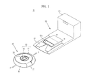
- FIG. 1 is a view illustrating a cleaning system according to an exemplary embodiment of the present disclosure.
- the cleaning system 10 may include a robot cleaner 20 and a maintenance station 60.
- the robot cleaner 20 is a device for autonomously performing various cleaning tasks.
- the maintenance station 60 is a device for repair and maintenance.
- the maintenance station 60 may charge a battery of the robot cleaner 20, and empties a dust box of the robot cleaner 20.
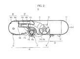
- FIG. 2 is a sectional view illustrating a configuration of the robot cleaner according to an exemplary embodiment of the present disclosure.
- FIG. 3 is a perspective view illustrating a bottom of the robot cleaner according to the illustrated embodiment of the present disclosure.
- the robot cleaner 20 includes a body 21, a driving unit 30, a cleaning unit 40, various sensors 50, and a controller (not shown).
- the body 21 may have various shapes.
- the body 21 may have a circular shape. Where the body 21 has a circular shape, it may be prevented from coming into contact with surrounding obstacles and may easily achieve direction change, even during rotation thereof, because it has a constant radius of rotation. Also, it may be possible to prevent the body 21 from being obstructed by a surrounding obstacle during travel thereof. Thus, the body 21 cannot be trapped by an obstacle during travel thereof.
- Various constituent elements to perform cleaning tasks that is, the driving unit 30, cleaning unit 40, various sensors 50, controller (not shown), and a display 23, may be installed on the body 21.
- the driving unit 30 may enable the body 21 to travel about a region to be cleaned.
- the driving unit 30 may include left and right driving wheels 31 a and 31 b, and a caster 32.
- the left and right driving wheels 31 a and 31 b are mounted to a central portion of a bottom of the body 21.
- the caster 32 is mounted to a front portion of the bottom of the body 21, to maintain stability of the robot cleaner 20.
- the left and right driving wheels 31 a and 31 b may be controlled to move the robot cleaner 20 forward or backward, or to change the running direction of the robot cleaner 20. For example, it may be possible to move the robot cleaner 20 forward or backward by uniformly controlling the left and right driving wheels 31 a and 31 b. Also, it may be possible to change the running direction of the robot cleaner 20 by differently controlling the left and right driving wheels 31 a and 31b.
- each of the left and right driving wheels 31 a and 31 b, and the caster 32 may be configured into a single assembly detachably mounted to the body 21.
- the cleaning unit 40 may clean the region underneath the body 21 and surrounding portions thereof.
- the cleaning unit 40 may include a brush unit 41, a side brush 42, and a first dust box 43.
- the brush unit 41 may be mounted to a first opening 21 a formed through the bottom of the body 21.
- the brush unit 41 may be arranged at a position other than the central portion of the body 21. That is, the brush unit 41 may be arranged at a position adjacent to the driving wheels 31 a and 31 b while being spaced apart from the driving wheels 31 a and 31 b in a rearward direction R of the body 21.
- the brush unit 41 may sweep dust accumulated on a floor beneath the body 21 into the first dust box 43.
- the brush unit 41 may include a roller 41 a rotatably mounted to the first opening 21 a, and a brush 41 b fixed to an outer peripheral surface of the roller 41 a.
- the brush 41 b which is made of an elastic material, may sweep up dust accumulated on the floor.
- the dust accumulated on the floor may be collected in the first dust box 43 through the first opening 21 a.
- the brush unit 41 may be controlled to rotate at a constant speed, in order to exhibit a uniform cleaning performance.
- the rotating speed thereof may be lowered, as compared to the case in which the brush unit 41 cleans a smooth floor surface. In this case, an increased amount of current may be supplied to keep the speed of the brush unit 41 constant.
- the side brush 42 may be rotatably mounted to a peripheral portion of the bottom of the body 21 at one side of the body 21.
- the side brush 42 may be mounted at a position spaced apart from the central portion of the body 21 in a forward direction F while being biased toward one side of the body 21.
- the side brush 42 may move dust accumulated around the body 21 to the brush unit 41.
- the side brush 42 may expand the cleaning zone of the robot cleaner 20 to the bottom of the body 21 and surroundings thereof.
- the dust moved to the brush unit 41 may be collected in the first dust box 43 through the first opening 21 a, as described above.
- the first dust box 43 may be mounted to a rear portion of the body 21.
- the first dust box 43 includes an inlet 43' communicating with the first opening 21 a, to allow dust to be introduced into the first dust box 43.
- the first dust box 43 may be divided into a larger dust box 43a and a smaller dust box 43b by a partition 43c.
- the brush unit 41 may sweep dust having a relatively-large size into the larger dust box 43a via the first inlet 43a'.
- a fan unit 22 may be provided to suck small-size dust such as hairs via a second inlet 43b', and thus to collect the dust in the smaller dust box 43b.
- a brush cleaning member 41 c is arranged at a position adjacent to the second inlet 43b'. The brush cleaning member 41 c removes hairs wound around the brush unit 41, and then collects the removed hairs in the smaller dust box 43b via the second inlet 43b', using a suction force of the fan unit 22.
- each of the brush unit 41, side brush 42, and first dust box 43 may be configured into a single assembly detachably mountable to the body 21.
- FIG. 4A is a plan view illustrating a dust sensing unit according to an exemplary embodiment of the present disclosure.
- FIG. 4B is a plan view illustrating a dust sensing unit according to another exemplary embodiment of the present disclosure.
- FIG. 4C is a plan view illustrating a dust sensing unit according to another exemplary embodiment of the present disclosure.
- the dust sensing unit may be installed within the first dust box 43, in order to sense the amount of dust in the first dust box 43.
- the dust sensing unit 44 may include a light emitting sensor 44a and a light receiving sensor 44b.
- a signal transmitted from the light emitting sensor 44a within the first dust box 43 may be directly received by the light receiving sensor 44b.
- Each of the light emitting sensor 44a and light receiving sensor 44b may include a photodiode or a phototransistor.
- the controller may determine that the first dust box 43 is completely filled with dust, when the sensed energy amount is less than the reference value.
- the light emitting sensor 44a and light receiving sensor 44b which are configured by photodiodes or phototransistors, are considerably influenced by disturbance, it may be possible to more accurately sense the amount of dust where a structure such as a slit or a light guide is installed to guide a signal transmitted from the light emitting sensor 44a or a signal received by the light receiving sensor 44b.
- Each of the light emitting sensor 44a and light receiving sensor 44b may also be configured by a remote-controller receiving module. In this case, it may be possible to determine whether or not the first dust box 43 is completely filled with dust, based on whether or not a signal has been received by the light receiving sensor 44b. That is, when dust is accumulated, the light receiving sensor 44b may not receive a signal transmitted from the light emitting sensor 44a. In this case, the controller may determine that the amount of dust in the first dust box 43 corresponds to a predetermined amount or more.
- the light emitting sensors 44a and light receiving sensor 44b which are remote-controller receiving modules, may not require a slit or light guide structure because they filter low-frequency waves while exhibiting high intensity and sensitivity.
- visible light, infrared light, sound waves, ultrasonic waves, etc. may be used.
- the dust sensing unit 44 may include a light emitting sensor 44a, a light receiving sensor 44b, and a reflecting member 44c.
- the light emitting sensor 44a and light receiving sensor 44b are not installed within the first dust box 43, but are instead installed in an area other than the first dust box 43. That is, the light emitting sensor 44a and light receiving sensor 44b may be installed at a portion of the body 21 facing the first dust box 43. In detail, the light emitting sensor 44a and light receiving sensor 44b may be installed adjacent to the inlet 43' of the first dust box 43. In this case, accordingly, the light emitting sensor 44a may transmit a signal into the first dust box 43 through the inlet 43'. The light receiving sensor 44b may receive the signal, which emerges from the first dust box 43 through the inlet 43' of the first dust box 43.
- the reflecting member 44c may be installed within the first dust box 43.
- the reflecting member 44c may reflect a signal emitted from the light emitting sensor 44a toward the light receiving sensor 44b.
- the controller may determine that the first dust box 43 is filled with a predetermined amount of dust or more.
- the light emitting sensors 44a and light receiving sensors 44b are configured by remote-controller modules, it may be unnecessary to use a slit or light guide structure because the light emitting sensors 44a and light receiving sensors 44b filter low-frequency waves while exhibiting high intensity and sensitivity, as described above. That is, the light emitting sensors 44a and light receiving sensors 44b, which are configured by remote-controller modules, may determine whether or not the first dust box 43 is completely filled with dust, even though there is no structure such as the reflecting member 44c within the first dust box 43.
- the light emitting sensor 44a and light receiving sensor 44b may not be installed within the first dust box 43, as described above, it may be unnecessary to install an electrical connecting terminal within the first dust box 43. Accordingly, the user may clean the first dust box 43, using water.
- the dust sensing unit 44 may also include a light emitting sensor 44a and a light receiving sensor 44b, which are configured as shown in FIG. 4C .
- the light emitting sensor 44a and light receiving sensor 44b need not be installed within the first dust box 43, and may instead be installed at regions other than the first dust box 43. That is, the light emitting sensors 44a and light receiving sensors 44b may be installed on the body 21, to face each other. In detail, the light emitting sensor 44a may be installed at a portion of the body 21 facing one side of the first dust box 43, whereas the light receiving sensor 44b may be installed at another portion of the body 21 facing the other side of the first dust box 43. In this case, the first dust box 43 is arranged between the light emitting sensor 44a and the light receiving sensor 44b, so that a signal transmitted from the light emitting sensor 44a may be received by the light receiving sensor 44b through the first dust box 43.
- the first dust box 43 may be formed to be completely transparent, so as to allow a signal to pass therethrough.
- the first dust box 43 may include a transparent transmitted-signal passing portion 43a" at a position corresponding to the light emitting sensor 44a, in order to allow a signal to pass therethrough, and a transparent received-signal passing portion 43b" at a position corresponding to the light receiving sensor 44b, in order to allow a signal to pass therethrough.
- the signal transmitted from the light emitting sensor 44a may be directly received by the light receiving sensor 44b.
- the light receiving sensor 44b does not sense any signal, or the amount of energy sensed by the light receiving sensor 44b may be considerably reduced.
- the controller may determine that the first dust box 43 is completely filled with dust.
- the robot cleaner 20 may display information about the sensed result on the display 23. The user may directly clean the first dust box 43. Meanwhile, the robot cleaner 20 may automatically dock with the maintenance station 60, to automatically discharge dust collected in the first dust box 43.
- the various sensors 50 which are mounted to the body 21, may be used to sense obstacles.
- a contact sensor, a proximity sensor, etc. may be used.
- a bumper 51 which is arranged at a front portion of the body 21, to be directed to a front direction F of the body 21, may be used to sense a front obstacle such as a wall. It may also be possible to sense a front obstacle, using an infrared sensor (or an ultrasonic sensor).
- An infrared sensor 52 (or an ultrasonic sensor), which is arranged on the bottom of the body 21, may be used to sense a condition of the floor, for example, condition of steps.
- a plurality of infrared sensors 52 may be installed on the bottom of the body 21 along an arc-shaped peripheral portion of the body 21.
- Various sensors other than the above-described sensors may also be installed on the body 21, to transfer various conditions of the robot cleaner 20 to the controller.
- the controller receives signals from the various sensors 50, and controls the driving unit 30 and cleaning unit 40, based on the received signals, thereby more efficiently controlling the robot cleaner 20.
- FIG. 5A is a perspective view illustrating a top perspective view illustrating a configuration of the maintenance station according to an exemplary embodiment of the present disclosure.
- FIG. 5B is a top perspective view illustrating a configuration of the maintenance station according to another exemplary embodiment of the present disclosure.
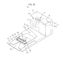
- FIG. 5C is a top perspective view illustrating a configuration of the maintenance station according to another exemplary embodiment of the present disclosure.
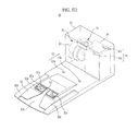
- FIG. 5D is a top perspective view illustrating a configuration of the maintenance station according to another exemplary embodiment of the present disclosure.
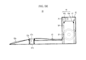
- FIG. 5E is a sectional view illustrating a configuration of the maintenance station according to another exemplary embodiment of the present disclosure.
- FIG. 6 is a plan view illustrating a duct included in the maintenance station according to the embodiment of FIG. 5A .
- FIG. 7 is a plan view illustrating the maintenance station according to the embodiment of FIG. 5A .
- the robot cleaner 20 may dock with the maintenance station 60 in various situations.
- there may be various situations such as a situation in which the battery (not shown) of the robot cleaner 20 needs to be charged, a situation in which the robot cleaner 20 has performed a cleaning task for a predetermined time, a situation in which the robot cleaner 20 has completed a cleaning task, and a situation in which the first dust box 43 of the robot cleaner 20 is completely filled with dust.
- the maintenance station 60 may include a housing 61, a docking guide unit 70, a charging unit 80, a dust removal unit 90, and a controller (not shown).
- a platform 62 may be provided at the housing 61.
- the platform 62 may support the robot cleaner 20 while the robot cleaner 20 docks with the maintenance station 60.
- the platform 62 has an inclined structure to allow the robot cleaner 20 to easily ascend along or descend from the platform 62.
- a caster guide 63a may be formed at the platform 62, to guide the caster 32 of the robot cleaner 20.
- Driving wheel guides 63b and 63c may also be formed at the platform 62, to guide the left and right driving wheels 31 a and 31 b of the robot cleaner 20.
- the caster guide 63a and driving wheel guides 63b and 63c may be formed to be recessed, as compared to portions of the platform 62 therearound.
- a second opening 62a may be formed through the platform 62.
- the second opening 62a of the platform 62 may be arranged at a position where the second opening 62a may communicate with the first opening 21 a of the robot cleaner 20.
- dust discharged through the first opening 21 a of the robot cleaner 20 may be introduced into the second opening 62a of the platform 62.
- the dust introduced into the second opening 62a of the platform 62 may be collected in a second dust box 94 included in the maintenance station 60.
- the second dust box 94 of the maintenance station 60 is different from the first dust box 43 of the robot cleaner 20.
- the first dust box 43 of the robot cleaner 20 stores dust collected by the robot cleaner 20 during movement of the robot cleaner 20.
- the second dust box 94 of the maintenance station 60 collects and stores dust discharged from the first dust box 43.
- the second dust box 94 of the maintenance station 60n may have a greater capacity than the first dust box 43 of the robot cleaner 20.
- the dust sensing unit 44 may also be installed within the second dust box 94, in order to sense the amount of dust in the second dust box 94.
- the dust sensing unit 44 may include a light emitting sensor 44a and a light receiving sensor 44b.
- the controller may determine that the amount of dust in the second dust box 94 corresponds to a predetermined amount or more.
- the second opening 62a of the platform 62 may have an open structure, as shown in FIG. 5A . That is, the second opening 62a of the platform 62 may always be open without being covered by a separate cover.
- the platform 62 may be formed to be inclined at a predetermined angle ⁇ or more ( FIG. 7 ).
- ⁇ a predetermined angle
- the front portion of the robot cleaner 20 may be slightly lifted because the weight of the robot cleaner 20 is rearwardly biased.
- the caster 32 of the robot cleaner 20 may pass the second opening 62a of the platform 62 without falling into the second opening 62a.
- a cover 64 may be installed at the second opening 62a of the platform 62, to slidably move along the second opening 62a, as shown in FIG. 5B .
- the cover 64 may be opened, to allow the robot cleaner 20 to discharge dust through the second opening 62a of the platform 62.
- the cover 64 may be closed to close the second opening 62a of the platform 62.
- the cover 64 may also function as a bridge upon which the caster 32 of the robot cleaner 20 will move.
- the cover 64 may be opened or closed in linkage with docking of the robot cleaner 20. That is, the cover 64 may be opened while or before the caster 32 passes the cover 64 during docking of the robot cleaner 20.
- the cover 64 may be closed while or after the caster 32 passes the cover 64 during docking release of the robot cleaner 20. It may also be possible to open or close the cover 64, using a separate device.
- a cover 65 may be installed at the second opening 62a of the platform 62, to slidably move along the second opening 62a.
- the cover 65 may be installed only at a central portion of the second opening 62a of the platform 62 in the case of FIG. 5C , different from the case of FIG. 5B .
- This structure is adapted to allow the caster 32 of the robot cleaner 20 to pass the second opening 62a of the platform 62.
- the opening/closing operation of the cover 65 may be achieved in the same manner as described above.
- a bridge 66 may be installed at the second opening 62a of the platform 62.
- the bridge 66 may be installed only at a central portion of the second opening 62a of the platform 62, to achieve a bridge function allowing the caster 32 of the robot cleaner 20 to pass the bridge 66.
- the bridge 66 may be installed at the second opening 62a of the platform 62 to move upward and downward. That is, when the robot cleaner 20 enters the platform 62, the bridge 67a moves upward to allow the caster 32 of the robot cleaner 20 to move thereon. When the docking of the robot cleaner 20 is completed, the bridge 67b moves downward to allow the second opening 62a of the platform 62 to secure an increased opening area.
- the docking guide unit 70 may be installed at an upper portion of the housing 61.
- the docking guide unit 70 may include a plurality of sensors 71.
- the sensors 71 may define a docking guide region and a docking region, to accurately guide the robot cleaner 20 to dock with the maintenance station 60.
- the charging unit 80 may be installed at the platform 62.
- the charging unit 80 may include a plurality of connecting terminals 81 a and 81 b.
- the connecting terminals 81 a and 81 b may correspond to a plurality of connecting terminals 23a and 23b provided at the robot cleaner 20.
- current may be supplied to the plural connecting terminals 23a and 23b of the robot cleaner 20 via the plural connecting terminals 81 a and 81 b of the maintenance station 60.
- the charging unit 80 may supply current after determining whether or not the plural connecting terminals 23a and 23b of the robot cleaner 20 are connected to the charging unit 80. That is, when the charging unit 80 is connected to an element other than the plural connecting terminals 23a and 23b, the charging unit 80 interrupts supply of current, to avoid occurrence of an accident.
- the dust removal unit 90 may be installed at the housing 61.
- the dust removal unit 90 may discharge dust stored in the first dust box 43 of the robot cleaner 20 into the second dust box 94 of the maintenance station 60, to empty the first dust box 43.
- the dust removal unit 90 may maintain desired cleaning performance of the robot cleaner 20.
- the dust removal unit 90 may include a pump unit 91, a suction duct 92, and a discharge duct 93, in addition to the second dust box 94.
- the dust removal unit 90 functions to force a flow of air discharged from the discharge duct 93 to be sucked back into the suction duct 92. Using such a circulating air flow, the dust removal unit 90 removes dust stored in the first dust box 43 of the robot cleaner 20.
- the pump unit 91 is a device to suck/discharge air.
- the pump unit 91 may include a fan and a motor.
- the suction duct 92 may be installed at a suction side of the pump unit 91.
- the suction duct 92 may include a suction port 92a, which may form a portion of the second opening 62a.
- the suction port 92a may be separate from the second opening 62a.
- the suction duct 92a may be arranged at a position adjacent to the second opening 62a.
- the suction port 92a may extend in a longitudinal direction of the second opening 62a, to occupy a portion of the second opening 62a, except for a portion of the second opening 62a occupied by discharge ports 93a and 93b of the discharge duct 93.
- the discharge duct 93 may be installed at a discharge side of the pump unit 91.
- the discharge duct 93 may be divided into two portions, which form the two discharge ports 93a and 93b.
- the discharge ports 93a and 93b may form portions of the second opening 62a.
- the discharge ports 93a and 93b may be separate from the second opening 62a.
- the discharge ports 93a and 93b may be arranged at positions adjacent to the second opening 62a.
- the discharge ports 93a and 93b may be formed at longitudinal ends of the second opening 62a, namely, opposite side regions of the second opening 62a, respectively.
- the suction port 92a of the suction duct 92 may have a larger cross-sectional area than the sum of the cross-sectional areas of the discharge ports 93a and 93b of the discharge duct 93.
- the sum of the cross-sectional areas of the discharge ports 93a and 93b of the discharge duct 93 will be simply referred to as "the cross-sectional area of the discharge ports 93a and 93b".
- the cross-sectional area ratio between the suction port 92a of the suction duct 92 and the discharge ports 93a and 93b of the discharge duct may be 7.5:1.
- the cross-sectional area ratio of the suction port 92a of the suction duct 92 to the discharge ports 93a and 93b of the discharge duct may be smaller than the above-described ratio, for example, may be 7:1, 6.5:1, or 6:1. Even when the cross-sectional area ratio is slightly reduced, as described above, it falls within the technical scope of the present disclosure.
- the air flow velocity at the discharge ports 93a and 93b of the discharge duct 93 may be higher than the air flow velocity at the suction port 92a of the suction duct 92 because there is a cross-sectional area difference between the suction port 92a and the discharge ports 93a and 93b under the condition that the suction flow rate and discharge flow rate of the pump unit 91 are substantially equal.
- this flow velocity difference it may be possible to prevent air emerging from the discharge ports 93a and 93b from being sucked into the suction port 92a.
- air emerging from the discharge ports 93a and 93b may be injected into the first dust box 34 without being directly sucked into the suction port 92a by a suction force at the suction port 92a, because the air flow velocity of the discharged air is very high.
- air injected into the first dust box 43 may emerge from the first dust box 43 after circulating through the first dust box 34, and may then enter the suction port 92a.
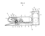
- FIG. 8 is a sectional view illustrating a docking state of the robot cleaner and maintenance station.
- the first opening 21 a of the robot cleaner 20 may communicate with the second opening 62a of the maintenance station 60.
- the suction port 92a of the suction duct 92 may be arranged adjacent to the first opening 21 a of the robot cleaner 20 while extending in the longitudinal direction of the first opening 21 a.
- the discharge ports 93a and 93b of the discharge duct 93 may be arranged adjacent to the first opening 21 a of the robot cleaner 20 at the longitudinal ends of the first opening 21 a of the robot cleaner 20, namely, the opposite side regions of the first opening 21 a, respectively.
- air circulated (returned) by the dust removing device 90 during the docking operation may form a closed loop. That is, air discharged from the pump unit 91 rapidly emerges from the discharge ports 93a and 93b of the discharge duct 93, and then enters the first dust box 43 of the robot cleaner 20 after passing through the opposite side regions of the first opening 21 a.
- the air introduced into the first dust box 43 of the robot cleaner 20 is discharged through the central region of the first opening 21 a, to be introduced into the second dust box 94 of the maintenance station 60 through the suction port 92a of the suction duct 92. Thereafter, the air is again sucked into the pump unit 91.
- FIG. 9A is a view illustrating a configuration of the brush cleaning member according to an exemplary embodiment of the present disclosure.
- FIG. 9B is a view illustrating a configuration of the brush cleaning member according to another exemplary embodiment of the present disclosure.
- FIG. 9C is a view illustrating a configuration of the brush cleaning member according to another exemplary embodiment of the present disclosure.
- the maintenance station 60 may include a brush cleaning member 95a to clean the brush unit 41 of the robot cleaner 20.
- the brush cleaning member 95a of the maintenance station 60 is different from the brush cleaning member 41 c of the robot cleaner 20.
- the brush cleaning member 95a of the maintenance station 60 may be arranged adjacent to the second opening 62a.
- the brush cleaning member 95a of the maintenance station 60 may be protruded from the bottom of the housing 61 toward the second opening 62a.
- the brush cleaning member 95a may include a plurality of brush cleaning members arranged in a longitudinal direction of the second opening 62a.
- the brush cleaning member 95a of the maintenance station 60 may be in contact with the brush unit 41 of the robot cleaner 20.
- the brush cleaning member 95a of the maintenance station 60 may remove foreign matter such as hairs wound around the brush unit 41 of the robot cleaner 20.
- the foreign matter removed by the brush cleaning member 95a of the maintenance station 60 may be introduced into the second dust box 94 by the suction force of the pump unit 91 because the brush cleaning member 95a of the maintenance station 60 may be arranged at the suction duct 92.
- the brush cleaning member 95b of the maintenance station 60 may be arranged to be slidably movable in the longitudinal direction of the second opening 62a, as shown in FIG. 9B .
- the brush cleaning member 95b of the maintenance station 60 may remove foreign matter wound around the brush unit 41 of the robot cleaner 20 while sliding.
- the brush cleaning member 95c of the maintenance station 60 may be installed to be upwardly and downwardly movable, as shown in FIG. 9C .
- the brush cleaning member 95c may move upward when the docking of the robot cleaner is completed, so that the brush cleaning member 95c comes into contact with the brush unit 41 of the robot cleaner 20.
- the brush cleaning member 95c may move downward. Meanwhile, the upward and downward movement of the brush cleaning member 95c may be carried out in linkage with docking of the robot cleaner 20.
- the brush unit 41 of the robot cleaner 20 may more effectively move dust in cooperation with the dust removal unit 90.
- the brush unit 41 of the robot cleaner 20 may rotate in a clockwise direction in FIG. 8 .
- the brush unit 41 of the robot cleaner 20 may assist introduction of air into the first dust box 43 of the robot cleaner 20.
- the brush unit 41 may assist introduction of air emerging from the first dust box 43 of the robot cleaner 20 into the suction port 92a of the suction duct 92.
- the brush unit 41 of the robot cleaner may rotate at various speeds, to more effectively move dust.
- the brush unit 41 of the robot cleaner 20 may slowly rotate in an early stage, and may then rapidly rotate.
- the "early stage” means a certain period of time. This period may be set to be a sufficient time to allow light dust such as hairs to be discharged.
- the brush unit 41 of the robot cleaner 20 rotates slowly in the early stage, foreign matter such as relatively-light hairs may be easily moved to the suction port 92a of the suction duct 92 by the suction force of the dust removal unit 90.
- relatively-heavy dust may be easily moved to the suction port 92a of the suction duct 92 by virtue of the rotating force of the brush unit 41.
- the brush unit 41 of the robot cleaner 20 may remove foreign matter wound around the brush unit 41 while changing the rotation direction thereof at least one time. Dust stored in the first dust box 43 of the robot cleaner 20 may be wound around the brush unit 41 of the robot cleaner 20 because it is discharged through the first opening 21 a of the robot cleaner 20 after passing the brush unit 41 of the robot cleaner 20. At this time, it may be possible to unwind the foreign matter wound around the brush unit 41 of the robot cleaner 20 by changing the rotation direction of the brush unit 41 of the robot cleaner 20. The unwound foreign matter is moved to the suction port 92a of the suction duct 92, and is then stored in the second dust box 94 of the maintenance station 60. Subsequently, the brush unit 41 of the robot cleaner 20 may again change the rotation direction, so as to rotate in the original direction. The brush unit 41 of the robot cleaner 20 may repeat the change of the rotation direction several times.
- the robot cleaner 20 may sense a signal from the docking guide unit 70, to accurately dock with the maintenance station 60 in accordance with the sensed signal. Docking is initiated as the body 21 enters the platform 62, starting from the front portion of the body 21. Docking is completed at a position where the first opening 231 a of the robot cleaner 20 communicates with the second opening 62a of the maintenance station 60.
- the dust removal unit 90 may discharge dust stored in the robot cleaner 20 to the maintenance station 60.
- the pump unit 91 may discharge air at a high flow velocity through the discharge ports 93a and 93b of the discharge duct 93.
- the air emerging from the discharge ports 93a and 93b may be introduced into the first dust box 43 after passing through the first opening 21 a of the robot cleaner 20.
- the air introduced into the first dust box 43 of the robot cleaner 20 may completely circulate the entire space of the first dust box 43 without forming a dead space in the first dust box 43.
- air emerging from the discharge ports 93a and 93b may completely stir dust, starting from the side portion of the first dust box 43, because the discharge ports 93a and 93b are arranged at the opposite side regions of the first opening 20a of the robot cleaner 20 as viewed in the longitudinal direction of the first opening 20a.
- the dust stored in the first dust box 43 may be suspended in the air introduced into the first dust box 43, and may then be discharged through the first opening 21 a, along with the air introduced into the first dust box 43.
- the suction port 92a of the suction duct 92 applies a suction force to the first opening 21 a of the robot cleaner 20, thereby causing dust emerging from the first dust box 43 of the robot cleaner 20 to be sucked.
- the dust introduced into the suction port 92a of the suction duct 92 may be stored in the second dust box 94 of the maintenance station 60. Air is again sucked into the pump unit 91 via a filter 94a.
- the air discharged from the pump unit 91 may be reintroduced into the pump unit 91 after sequentially passing through the discharge duct 93, the first opening 21 a of the robot cleaner 20, the first dust box 43 of the robot cleaner 20, the first opening 21 a of the robot cleaner 20, the suction duct 92, and the second dust box 94 of the maintenance station 60.
- air circulates (returns) as described above, it may be possible to maximally prevent outward discharge of air. Accordingly, it may be possible to reduce the performance of the filter 94a.
- Dust emerging from the first dust box 43 of the robot cleaner 20 may be moved to a large central region of the first opening 21 a of the robot cleaner 20 and a large central region of the second opening 62a of the maintenance station 60 because the air emerging from the discharge ports 93a and 93b of the discharge duct 93 may be discharged through the opposite side regions of the first opening 21 a of the robot cleaner 20 and second opening 62a of the maintenance station 60 as viewed in the longitudinal direction of the first and second openings 21 a and 62a, and the air sucked at the suction port 92a of the suction duct 92 may be sucked through the large regions of the first opening 21 a of the robot cleaner 20 and second opening 62a of the maintenance station 60 as viewed in the longitudinal direction of the first and second openings 21 a and 62a.
- the arrangements of the suction port 92a and discharge ports 93a and 93b may prevent dust emerging from the first dust box 43 of the robot cleaner 20 from moving through the opposite side regions, and thus may prevent the dust from being outwardly discharged.
- the positions of the suction port 92a and discharge ports 93a and 93b with regard to the first opening 21 a of the robot cleaner 20 and the second opening 62a of the maintenance station 60 may provide a certain sealing effect between the robot cleaner 20 and the maintenance station 60.
- the brush unit 41 may be controlled to rotate slowly in an early stage, and then to rotate rapidly while the dust removal unit 90 circulates air, in order to assist the dust removal unit 90.
- the brush unit 41 assists, in the early stage, the dust removal unit 90 to rapidly suck light dust such as hairs while rotating slowly. Subsequently, the brush unit 41 assists the dust removal unit 90 to suck relatively-heavy dust while rotating rapidly.
- the brush unit 41 may be controlled to change the rotation direction thereof at least one time while the dust removal unit 90 circulates air, in order to assist the dust removal unit 90.
- foreign matter such as hairs may be wound around the brush unit 41.
- the wound foreign matter such as hairs may be unwound as the rotation direction of the brush unit 41 is changed.
- the dust removal unit 90 may suck the foreign matter such as hairs off of the brush unit 41.
- the brush cleaning member 95 of the maintenance station 60 may remove foreign mater such as hairs wound around the brush unit 41 of the robot cleaner 20.
- Foreign matter wound around the brush unit 41 of the robot cleaner 20 during rotation of the brush unit 41 comes into contact with the brush cleaning member 95 of the maintenance station 60, so that the foreign matter may be removed from the brush unit 41 by the brush cleaning member 95 of the maintenance station 60.
- the removed foreign matter may be collected in the second dust box 94 by the suction force of the dust removal unit 90.
- FIG. 10 is a view schematically illustrating a cleaning system according to another exemplary embodiment of the present disclosure.
- FIG. 11 is a perspective view illustrating a suction/discharge dual tube.
- FIG. 12 is a view illustrating flow of air in the cleaning system according to the embodiment shown in FIG. 10 .
- the cleaning system 100 may discharge dust stored in a first dust box 143 included in a robot cleaner 120 to a second dust box 194 included in a maintenance station 160.
- the following description will be given only in conjunction with matters different from those of the previous embodiments.
- the maintenance station 160 may include a suction/discharge dual tube 200, to which a suction air flow and a discharge air flow are applied.
- suction air flow is an air flow emerging from the first dust box 143 of the robot cleaner 120
- discharge air flow is an air flow introduced into the first dust box 143 of the robot cleaner 120.
- the first dust box 143 of the robot cleaner 120 may be coupled with the suction/discharge dual tube 200 of the maintenance station 160 via a communicating member 145.
- the suction/discharge dual tube 200 may have a concentric dual tube structure.
- the suction/discharge dual tube 200 may include a discharge tube 293 arranged at a central portion of the suction/discharge dual tube 200, and a suction tube 292 surrounding an outer peripheral surface of the discharge tube 293.
- the suction/discharge dual tube may have a parallel dual tube structure in accordance with another embodiment.
- the suction/discharge dual tube may include suction and discharge tubes arranged in parallel in a longitudinal direction or in a lateral direction.
- the maintenance station 160 may include a dust removal unit 190.
- the dust removal unit 190 may include a pump unit 191, a suction duct 192 installed at a suction side of the pump unit 191, and connected to the suction tube 292 of the suction/discharge dual tube 200, a discharge duct 193 installed at a discharge side of the pump unit 191, and connected to the discharge tube 293 of the suction/discharge dual tube 200, and a second dust box 194.
- air discharged from the pump unit 191 may be introduced into the first dust box 143 of the robot cleaner 120 after entering the discharge tube 293 of the suction/discharge dual tube 200 via the discharge duct 193. Thereafter, the air introduced into the first dust box 143 may pass through the suction duct 192 after being sucked into the suction tube 292 of the suction/discharge dual tube 200, along with dust stored in the first dust box 143. The dust passing through the suction duct 192 may be stored in the second dust box 194, and may then be sucked into the pump unit 191 again.
- the air discharged from the pump unit 191 may be reintroduced into the pump unit 191 after sequentially passing through the discharge duct 193, the discharge tube 293 of the suction/discharge dual tube 200, the first dust box 143 of the robot cleaner 120, the suction tube 292 of the suction/discharge dual tube 200, the suction duct 192, and the second dust box 194 of the maintenance station 160.
- FIG. 13 is a view schematically illustrating a cleaning system according to another embodiment of the present disclosure.
- the cleaning system 300 may discharge dust stored in a first dust box 343 included in a robot cleaner 320 to a second dust box 394 included in a maintenance station 360.
- a first dust box 343 included in a robot cleaner 320 may discharge dust stored in a first dust box 343 included in a robot cleaner 320 to a second dust box 394 included in a maintenance station 360.
- the first dust box 343 of the robot cleaner 320 may include an inlet communicating with a first opening 321 a included in the robot cleaner 320, and a communicating member 345 to directly communicate with the maintenance station 360.
- the maintenance station 360 may include a dust removal unit 390.
- the dust removal unit 390 may include a pump unit 391, a suction duct 392 installed at a suction side of the pump unit 391, and a discharge duct 393 installed at a discharge side of the pump unit 391.
- the first opening 321 a of the robot cleaner 320 may be connected to the suction duct 392 of the maintenance station 360, and the communicating member 345 of the first dust box 343 in the robot cleaner 320 may be connected to the discharge duct 393 of the maintenance station 360.
- Air discharged from the pump unit 391 may be introduced into the first dust box 343 of the robot cleaner 320 via the discharge duct 393.
- the air introduced into the first dust box 343 of the robot cleaner 320 may be moved to the suction duct 392 after passing through the inlet 343' of the first dust box 343 and the first opening 321 a of the robot cleaner 320, along with dust stored in the first dust box 343.
- the dust moved to the suction duct 392 is stored in the second dust box 394 of the maintenance station 360, whereas the air may be sucked into the pump unit 391 again.
- the air discharged from the pump unit 391 may be reintroduced into the pump unit 391 after sequentially passing through the discharge duct 393, communicating member 345 of the first dust box 343, the first dust box 343 of the robot cleaner 320, the inlet 343' of the first dust box 343, the suction duct 392, and the second dust box 394 of the maintenance station 360.
- FIG. 14 is a view schematically illustrating a cleaning system according to another embodiment of the present disclosure.
- the cleaning system 400 may discharge dust stored in a first dust box 443 included in a robot cleaner 420 to a second dust box 494 included in a maintenance station 460.
- the following description will be given only in conjunction with matters different from those of the previous embodiments.
- a first opening 421 a of the robot cleaner 420 may be connected to a discharge duct 493 of the maintenance station 460, and a communicating member 445 included in the first dust box 443 of the robot cleaner 420 may be connected to a suction duct 492 of the maintenance station 460.
- Air discharged from the pump unit 491 may be introduced into the first dust box 443 of the robot cleaner 320 via the discharge duct 493, the first opening 421 a of the robot cleaner 420, and an inlet 443' of the first dust box 443.
- the air introduced into the first dust box 443 of the robot cleaner 420 may be moved to the suction duct 492 after passing through the communicating member 445 of the first dust box 443, along with dust stored in the first dust box 443.
- the dust moved to the suction duct 492 is stored in the second dust box 494 of the maintenance station 460, whereas the air may be sucked into the pump unit 491 again.
- the air discharged from the pump unit 491 may be reintroduced into the pump unit 491 after sequentially passing through the discharge duct 493, the inlet 443' of the first dust box 443, the first dust box 443 of the robot cleaner 420, the communicating member 445 of the first dust box 443, the suction duct 492, and the second dust box 494 of the maintenance station 460.
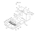
- FIG. 15 is a top perspective view illustrating a configuration of the maintenance station according to another exemplary embodiment of the present disclosure.
- FIG. 16 is an exploded perspective view illustrating a configuration of the maintenance station according to the illustrated embodiment of the present disclosure.
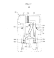
- FIG. 17 is a plan view illustrating a duct included in the maintenance station according to the illustrated embodiment of the present disclosure.
- FIG. 18 is a sectional view illustrating a flow of air discharged through a second opening during a docking operation.
- FIG. 19 is a sectional view illustrating a flow of air sucked through the second opening during the docking operation.
- FIG. 20 is a top perspective view illustrating a port assembly according to another exemplary embodiment of the present disclosure.
- FIG. 21 is a bottom perspective view illustrating the port assembly according to the illustrated embodiment of the present disclosure.
- the cleaning system 510 has the same basic structure as the above-described cleaning system 10. Accordingly, the following description will be given mainly in conjunction with portions of the cleaning system 510 different from the cleaning system 10, and no description will be given of the same portions of the cleaning system 510 as the cleaning system 10, if possible.
- the maintenance station 560 may include a housing 561, a docking guide unit 570, a charging unit 580, a dust removal unit 590, and a controller (not shown).
- a platform 562 may be provided at the housing 561.
- a second opening 562a may be formed at the platform 562.
- the second opening 562a of the platform 562 is arranged at a position where the second opening 562a may communicate with a first opening 521a of the robot cleaner 520. Dust discharged through the first opening 521a of the robot cleaner 520 may be introduced into the second opening 562a of the platform 562, and is then stored in a second dust box 594 of the maintenance station 560.
- the second opening 562a of the platform 562 may be larger than the first opening 521 a of the robot cleaner 520.
- the dust removal unit 590 may be installed at the housing 561.
- the dust removal unit 590 may discharge dust stored in the first dust box 543 of the robot cleaner 520 into the second dust box 594 of the maintenance station 560, to empty the first dust box 543.
- the dust removal unit 590 may maintain desired cleaning performance of the robot cleaner 520.
- the dust removal unit 590 may include a pump unit 591, a suction duct 592, a first discharge duct 593a, a second discharge duct 593b, a port assembly 600, and a suction/discharge dual tube 200, in addition to the second dust box 594.
- the dust removal unit 590 functions to force air discharged from the first and second discharge ducts 593a and 593b to be sucked back into the suction duct 592. Using such a circulating air flow, the dust removal unit 590 removes dust stored in the first dust box 543 of the robot cleaner 520.
- the suction duct 592 may be installed at a suction side of the pump unit 591.
- the first and second discharge ducts 593a and 593b may be installed at a discharge side of the pump unit 591.
- the port assembly 600 may be separably mounted to the second opening 562a. The port assembly 600 communicates with the suction duct 592, first discharge duct 593a, and second discharge duct 593b.
- the port assembly 600 may include a suction port forming member 610, a first discharge port forming member 621, a second discharge port forming member 622, a third discharge port forming member 623, a fourth discharge port forming member 624, and a brush cleaning member 630.
- the suction port forming member 610 divides the suction duct 592 into two portions, which form first and second suction ports 592a and 592b, respectively.
- First spacers 610a and 610b are formed at a lower surface of the suction port forming member 610.
- the first spacers 610a and 610b function to space the suction port forming member 610 from the bottom of the housing 561.
- Air or dust introduced into the first suction port 592a flows toward the suction duct 592 along an upper surface of the suction port forming member 610.
- Air or dust introduced into the second suction port 592b flows toward the suction duct 592 along a lower surface of the suction port forming member 610.
- the dust is subsequently stored in the second dust box 594 of the maintenance station 560.
- the first discharge port forming member 621 and second discharge port forming member 622 divide the first discharge duct 593a, into two portions, which form first and second discharge ports 593a' and 593a", respectively.
- the third discharge port forming member 623 and fourth discharge port forming member 624 divide the second discharge duct 593b, into two portions, which form third and fourth discharge ports 593b' and 593b", respectively.
- Air discharged through the first discharge port 593a' and third discharge port 593b' is fed to a large dust box 543a of the robot cleaner 520, whereas air discharged through the second discharge port 593a" and fourth discharge port 593b" is fed to a small dust box 543b of the robot cleaner 520.
- the first discharge port 593a' and third discharge port 593b' directly face the large dust box 543a. Accordingly, air discharged through the first discharge port 593a' and third discharge port 593b' is fed to the large dust box 543a while passing through the brush unit 541 at high flow rate.
- the second discharge port 593a" and fourth discharge port 593b" do not directly fact the small dust box 543b. For this reason, air discharged through the second discharge port 593a” and fourth discharge port 593b” is guided by a brush drum 540a, to be fed to the small dust box 543b.
- the brush unit 541 rotates in a counterclockwise direction in FIG. 18 , air discharged through the second discharge port 593a" and fourth discharge port 593b" may be more smoothly fed to the small dust box 543b.
- the first discharge port 593a' and third discharge port 593b' are arranged at opposite longitudinal (or lateral) ends of the second opening 562a, namely, opposite side regions of the second opening 562a, respectively.
- the second discharge port 593a" and fourth discharge port 593b" are arranged at opposite longitudinal (or lateral) ends of the second opening 562a, namely, opposite side regions of the second opening 562a, respectively.
- the first discharge port 593a' and second discharge port 593a" are arranged at opposite ends of the second opening 562a in a width (forward or backward) direction in one side region of the second opening 562a, respectively.
- the third discharge port 593b' and fourth discharge port 593b" are arranged at opposite ends of the second opening 562a in the width (forward or backward) direction in the other side region of the second opening 562a, respectively.
- the first discharge port 593a' to fourth discharge port 593b" are arranged at respective corner regions of the second opening 562a.
- second spacers 622a and 624a are formed at side walls of the second discharge port forming member 622 and fourth discharge port forming member 624, respectively.
- the second spacers 622a and 624a function to prevent the port assembly 600 from being biased toward one side of the second opening 562a.
- the second suction port 592b may be formed to have a structure surrounding the first suction port 592a, first discharge port 593a', second discharge port 593a", third discharge port 593b', and fourth discharge port 593b".
- the area occupied by the first suction port 592a and the first to fourth discharge ports 593a', 593a", 593b', and 593b" corresponds to the area of the first opening 521 a of the robot cleaner 520.
- the second suction port 592b may suck dust dispersed outside the first opening 521 a of the robot cleaner 520 because it is arranged outside the first opening 521a of the robot cleaner 520.
- a cover 640 formed with a plurality of through holes 640a may be mounted to the second suction port 592a. In this case, dust dispersed outside the first opening 521 a of the robot cleaner 520 may be sucked into the second suction port 592b through the through holes 640a. Normally, the cover 640 prevents foreign matter having a large size from entering the second suction port 592a, thereby preventing the suction passage from becoming clogged.
- the brush cleaning member 630 is formed at the suction port forming member 610, to be protruded from the suction port forming member 610, and thus to come into contact with brushes 541 b of the brush unit 541.
- a plurality of brush cleaning members 630 may be installed to be arranged in a longitudinal direction of the suction port forming member 610, as in the illustrated case. In the illustrated case, the brush cleaning members 630 are arranged in two rows in the longitudinal direction of the suction port forming member 610. In another embodiment, a plurality of brush cleaning members 630 may be arranged in one row, two rows, or more.
- the brush cleaning member 630 may include a guide 631 and a hook 632.
- the guide 631 extends inclinedly with respect to a rotation direction of the brush unit 541.
- the hook 632 is protruded from a side surface of an end of the guide 631.
- the brushes 541 b which are made of an elastic material, are inclined in the inclined direction of the guide 631 while coming into contact with the guide 631. Accordingly, foreign matter, which may be hairs wound around the brushes 541 b, may be caught by the hook 632 which, in turn, separates the foreign matter from the brushes 541 b.
- a plurality of guides 631 may be arranged in a longitudinal direction of the suction port forming member 610, and a plurality of hooks 632 may be protruded from side surfaces of guides 631, respectively.
- the guides 631 which are arranged in the longitudinal direction of the suction port forming member 610, may be laterally symmetrically arranged.
- a plurality of suction/discharge dual tubes 200 may be provided at the platform 562.
- the plural suction/discharge dual tubes 200 are arranged at positions corresponding to a plurality of infrared sensors 552 installed on a bottom of the robot cleaner 520.
- the concrete shape of each suction/discharge dual tubes 200 may be referred to the description given with reference to FIG. 11 .
- Each suction/discharge dual tube 200 generates a suction air flow and a discharge air flow.
- the suction air flow is an air flow introduced into the housing 561 through a suction tube 292 communicating with the suction duct 592
- the discharge air flow is an air flow outwardly discharged from the housing 561 through a discharge tube 293 communicating with the first discharge duct 593a or second discharge duct 593b.
- the infrared sensors 552 of the robot cleaner 520 may be cleaned by air flowing through the corresponding suction/discharge dual tubes 200, respectively. That is, air is blown to each infrared sensor 552 of the robot cleaner 520 through the discharge tube 293 of the corresponding suction/discharge dual tube 200, to remove dust from the infrared sensor 552, and the removed dust is then sucked through the suction tube 292 of the corresponding suction/discharge dual tube 200. The dust introduced into the suction tube 292 is collected in the second dust box 594 of the maintenance station 560.
- each infrared sensor 552 is removed, so that desired sensing performance may be maintained. Since the dust removed from the infrared sensor 552 is sucked back without being dispersed, the surroundings of the station 560 may be kept clean.
- the cleaning system according to each of the illustrated embodiments may prevent the cleaning performance of the robot cleaner from being degraded.
- the cleaning system may also achieve a reduction in energy and material costs by circulating air between the robot cleaner and the maintenance station.
- the cleaning system may also easily achieve automatic dust discharge by discharging dust through the opening of the robot cleaner.
- the cleaning system may cut off dust dispersed during automatic dust discharge, thereby keeping clean the surroundings of the maintenance station.
- the cleaning system also may clean the sensors using circulating discharge air, thereby preventing dust from dispersed around the surroundings of the cleaning system.
- the cleaning system may effectively remove foreign matter wound on the brush unit during automatic dust discharge.
Abstract
Description
- Embodiments of the present disclosure relate to a system for performing a cleaning operation using an autonomous robot.
- An autonomous robot is a device for performing a desired task while traveling about a certain region without being operated by a user. Such a robot may substantially operate autonomously. Autonomous operation may be achieved in various manners. In particular, a robot cleaner is a device for removing dust from a floor while traveling about a region to be cleaned without being operated by a user. In detail, such a robot cleaner may perform a vacuum cleaning operation and a wiping operation in a home. Here, dust may mean (soil) dust, mote, powder, debris, and other dust particles.
- Therefore, it is an aspect of the present disclosure to provide a cleaning system capable of preventing the cleaning performance of a robot cleaner from being degraded.
- Additional aspects of the disclosure will be set forth in part in the description which follows and, in part, will be obvious from the description, or may be learned by practice of the disclosure.
- In accordance with one aspect of the present disclosure, a robot cleaner includes a body having an opening, a dust box provided at the body, to store dust, and a brush unit provided at the opening of the body, to sweep dust on a floor into the dust box, wherein the dust swept into the dust box is suspended in air introduced into the dust box through the opening of the body, and is then discharged through the opening of the body.
- The air may be introduced into the dust body through a side region of the opening of the body, and may then be outwardly discharged through a central region of the opening of the body. The robot cleaner may further include a brush unit provided at the body such that the brush unit is rotatable. The brush unit may be controlled to allow dust to be more effectively discharged.
- The brush unit may include a roller, and the roller of the brush unit changes a rotation direction at least one time during the dust discharge.
- During the dust discharge, the roller of the brush unit may rotate slowly in an initial period of time when light dust is discharged, and may then rotate rapidly.
- The robot cleaner may further include a maintenance station to generate a flow to discharge air toward the body, and a flow to suck air from the body. The opening of the body may communicate with an opening provided at the maintenance station.
- In accordance with another aspect of the present disclosure, a maintenance station blows air into a dust box included in a robot cleaner through an opening of the robot cleaner where a brush unit is installed, and sucks dust stored in the dust box while being suspended in the air blown into the dust box.
- The air sucked from the dust box of the robot cleaner may be re-blown into the dust box through the opening of the robot cleaner.
- The maintenance station may further include an opening to communicate with the opening of the robot cleaner. The dust stored in the dust box of the robot cleaner may be discharged to the opening of the robot cleaner, so as to be introduced into the opening of the maintenance station.
- The maintenance station may further include a pump unit, a suction duct provided at a suction side of the pump unit, and a discharge duct provided at a discharge side of the pump unit. The suction duct may have a suction port arranged at the opening of the maintenance station, and the discharge duct may have a discharge port arranged at the opening of the maintenance station.
- The maintenance station may further include a pump unit, a suction duct provided at a suction side of the pump unit, and a discharge duct provided at a discharge side of the pump unit. The suction duct may have a suction port arranged at the opening of the maintenance station. The discharge duct may have a discharge port. The suction port and the discharge port may form the opening of the maintenance station.
- The suction port of the suction duct may be formed at a large region of the opening in the maintenance station in a longitudinal direction of the opening, and the discharge port of the discharge duct may be formed at an end region of the opening as viewed in the longitudinal direction of the opening.
- The suction port of the suction duct may have a larger cross-sectional area than the discharge port of the discharge duct.
- The maintenance station may further include a dust box arranged between the suction duct and the pump unit. Air discharged from the pump unit may be circulated to the pump unit after sequentially passing through the discharge duct, the opening of the robot cleaner, the dust box of the robot cleaner, the opening of the robot cleaner, the suction duct, and the dust box of the maintenance station.
- The discharge duct may include a first discharge duct having a first discharge port to allow air to be blown into a larger dust box included in the dust box of the robot cleaner, and a second discharge port to allow air to be blown into a smaller dust box included in the dust box of the robot cleaner.
- The first and second discharge ports of the first discharge duct may be arranged at opposite ends of the second opening in a width direction in one side region of the second opening, respectively.
- The discharge duct may include a second discharge duct having a third discharge port to allow air to be blown into a larger dust box included in the dust box of the robot cleaner, and a fourth discharge port to allow air to be blown into a smaller dust box included in the dust box of the robot cleaner.
- The third and fourth discharge ports of the first discharge duct may be arranged at opposite ends of the second opening in a width direction in the other side region of the second opening, respectively.
- The maintenance station may further include a suction/discharge dual tube to guide air to be blown to a sensor provided at the robot cleaner and to be again sucked from the sensor.
- The maintenance station may further include a pump unit, a suction duct provided at a suction side of the pump unit, and a discharge duct provided at a discharge side of the pump unit. The suction duct may communicate with a suction tube of the suction/discharge dual tube, and the discharge duct may communicate with a discharge tube of the suction/discharge dual tube.
- The maintenance station may further include a pump unit, a suction duct provided at a suction side of the pump unit, and a port assembly to divide the suction duct into two portions respectively having first and second suction ports.
- The port assembly may include a suction port forming member to form the first and second suction ports.
- The second suction port may surround at least a portion of the first suction port.
- The first suction port may be provided at a position substantially corresponding to the opening of the robot cleaner. At least a portion of the second suction port is arranged outside the opening of the robot cleaner.
- A cover having a plurality of through holes may be provided at the second suction port.
- The maintenance station may further include a pump unit, first and second discharge ducts provided at a discharge side of the pump unit, and a port assembly to divide the first discharge duct into two portions respectively having first and second discharge ports, and to divide the second discharge duct into two portions respectively having third and fourth discharge ports.
- The port assembly may include a first discharge port forming member to form the first discharge port, a second discharge port forming member to form the second discharge port, a third discharge port forming member to form the third discharge port, and a fourth discharge port forming member to form the fourth discharge port.
- The second suction port may surround at least a portion of each of the first, second, third and fourth discharge ports.
- The port assembly may further include a plurality of brush cleaning members to clean the brush unit of the robot cleaner.
- Each of the plural brush cleaning members may include a guide extending inclinedly with respect to a rotation direction of the brush unit, and at least one hook protruded from a side surface of the guide.
- The port assembly may be detachably mounted to the opening of the maintenance station.
- The port assembly may further include a first spacer provided at a bottom of the port assembly, and second spacers provided at opposite sides of the first spacer.
- The opening of the maintenance station may be larger than the opening of the robot cleaner.
- The maintenance station may further include a pump unit, and a suction duct provided at a suction side of the pump unit. The suction duct may have a suction port, which is larger than the opening of the robot cleaner.
- In accordance with another aspect of the present disclosure, a cleaning system includes a robot cleaner including a first opening, and a first dust box communicating with the first opening, and a maintenance station including a second opening, and a second dust box communicating with the second opening, wherein dust stored in the first dust box of the robot cleaner is discharged to the second opening of the maintenance station through the first opening of the robot cleaner after being suspended in air introduced into the first dust box of the robot cleaner.
- The air introduced into the first dust box of the robot cleaner may pass through the first opening of the robot cleaner.
- The cleaning system may further include a dust removal unit to suck air from the first dust box of the robot cleaner through the first opening of the robot cleaner, and to again blow air to the first opening of the robot cleaner.
- The dust removal unit may suck air such that the air blown to the first opening of the robot cleaner emerges from the first opening of the robot cleaner after circulating through the first dust box of the robot cleaner.
- The dust removal unit may blow air in a side region of the first opening of the robot cleaner as viewed in a longitudinal direction of the first opening, and may suck air in a large region of the first opening as viewed in the longitudinal direction of the first opening.
- The dust removal unit may include a pump unit, and a first discharge duct provided at a discharge side of the pump unit. The first discharge duct may have a first discharge port to allow air to be blown into a larger dust box included in the first dust box, and a second discharge port to allow air to be blown into a smaller dust box included in the first dust box.
- The dust removal unit may further include a second discharge duct provided at the discharge side of the pump unit. The second discharge duct may have a third discharge port to allow air to be blown into the larger dust box of the first dust box, and a fourth discharge port to allow air to be blown into a smaller dust box included in the first dust box.
- The dust removal unit may include a pump unit, and a suction duct provided at a suction side of the pump unit. The suction duct may have a suction port, which is larger than the opening of the robot cleaner.
- The dust removal unit may include a pump unit, a suction duct provided at a suction side of the pump unit, first and second discharge ducts provided at a discharge side of the pump unit, and a port assembly to divide the suction duct into two portions respectively having first and second suction ports, to divide the first discharge duct into two portions respectively having first and second discharge ports, and to divide the second discharge duct into two portions respectively having third and fourth discharge ports.
- The port assembly may include a suction port forming member to form the first and second suction ports, a first discharge port forming member to form the first discharge port, a second discharge port forming member to form the second discharge port, a third discharge port forming member to form the third discharge port, and a fourth discharge port forming member to form the fourth discharge port.
- The second suction port may surround the first suction port, the first discharge port, the second discharge port, the third discharge port, and the fourth discharge port.
- The dust removal unit may include a pump unit, a suction duct provided at a suction side of the pump unit, and a discharge duct provided at a discharge side of the pump unit. The suction duct may have a suction port arranged in a large region of the first opening of the robot cleaner in a longitudinal direction of the first opening, and the discharge duct may have a discharge port arranged at a side region of the first opening as viewed in the longitudinal direction of the first opening.
- The suction port of the suction duct may have a larger cross-sectional area than the discharge port of the discharge duct.
- A cross-sectional area ratio between the suction port of the suction duct and the discharge port of the discharge duct may be 7.5:1.
- The suction port of the suction duct and the discharge port of the discharge duct may form the second opening of the maintenance system.
- The maintenance station may further include a cover to open or close the second opening of the maintenance station.
- The maintenance station may further include a bridge extending along a central portion of the second opening of the maintenance station.
- The robot cleaner may further include a brush unit provided at the first opening of the robot cleaner. The brush unit may be controlled to allow dust stored in the first dust box of the robot cleaner to be more effectively discharged to the second opening of the maintenance station.
- The brush unit may include a roller, and the roller of the brush unit changes a rotation direction at least one time during the dust discharge.
- The roller may rotate slowly in an initial period of time when light dust is discharged, and may then rotate rapidly.
- The maintenance station may further include a brush cleaning member to clean the brush unit.
- The brush cleaning member may be arranged adjacent to the second opening of the maintenance station.
- The brush cleaning member may include a guide extending inclinedly with respect to a rotation direction of the brush unit, and at least one hook protruded from a side surface of the guide.
- The robot cleaner may further include a dust sensing unit to sense an amount of dust stored in the first dust box. The dust sensing unit may include a light emitting sensor and a light receiving sensor, which are installed at regions other than the first dust box, and a reflecting member installed in the first dust box, to reflect a signal transmitted from the light emitting sensor to the light receiving sensor.
- The robot cleaner may further include a dust sensing unit to sense an amount of dust stored in the first dust box. The robot cleaner may be moved to the maintenance station when the dust amount sensed by the dust sensing unit corresponds to a predetermined amount or more.
- In accordance with another aspect of the present disclosure, a cleaning system includes docking a robot cleaner at a maintenance station, determining whether or not docking is completed, discharging dust stored in the robot cleaner into the maintenance station through an opening where a brush unit included in the robot cleaner is installed, upon completion of docking, and operating a brush unit of the robot cleaner during dust discharge.
- The brush unit may change a rotation direction at least one time.
- The brush unit may rotate slowly in an initial period of time when light dust is discharged, and may then rotate rapidly.
- The cleaning system may further include determining whether or not dust is completely filled in a dust box of the robot cleaner.
- In accordance with another aspect of the present disclosure, a robot cleaner includes a body, a dust box provided at the body, to store dust, and a dust sensing unit to measure an amount of dust stored in the dust box, wherein the dust sensing unit includes a light emitting sensor installed at a region other than the dust box, to transmit a signal to an interior of the dust box, and a light receiving sensor installed at a region other than the dust box, to sense a signal emerging from the interior of the dust box.
- The dust sensing unit may further include a reflecting member installed within the dust box, to reflect the signal transmitted from the light emitting sensor to the light receiving sensor.
- The dust box may include at least one inlet, through which dust is introduced into the dust box. The light emitting sensor and the light receiving sensor may be provided at a portion of the body corresponding to the inlet of the dust box, to perform signal transmission and signal reception through the inlet of the dust box, respectively.
- The robot cleaner may further include a display provided at the body, to display various information. The display unit may display dust sensing information from the dust sensing unit.
- There may be no connecting terminal connected to the dust box.
- In accordance with another aspect of the present disclosure, a robot cleaner may include a body, a dust box provided at the body, to store dust, and a dust sensing unit to measure an amount of dust stored in the dust box. The dust sensing unit may include a light emitting sensor installed at a region other than the dust box. A signal transmitted from the light emitting sensor may reach the light receiving sensor after passing through the dust box.
- The dust box may be made of a transparent material to allow a signal to pass through the dust box.
- The light emitting sensor and the light receiving sensor may be installed so as to face each other.
- The dust box may include a transmitted-signal passing portion arranged at a position corresponding to the light emitting sensor, to allow a signal to enter the dust box, and a received-signal passing portion arranged at a position corresponding to the light receiving sensor, to allow a signal to emerge from the dust box.
- The transmitted-signal passing portion and the received-signal passing portion may be made of a transparent material.
- There may be no connecting terminal connected to the dust box.
- These and/or other aspects of the disclosure will become apparent and more readily appreciated from the following description of the embodiments, taken in conjunction with the accompanying drawings of which:
-
FIG. 1 is a view illustrating a cleaning system according to an exemplary embodiment of the present disclosure; -
FIG. 2 is a sectional view illustrating a configuration of the robot cleaner according to an exemplary embodiment of the present disclosure; -
FIG. 3 is a perspective view illustrating a bottom of the robot cleaner according to the illustrated embodiment of the present disclosure; -
FIG. 4A is a plan view illustrating a dust sensing unit according to an exemplary embodiment of the present disclosure; -
FIG. 4B is a plan view illustrating a dust sensing unit according to another exemplary embodiment of the present disclosure; -
FIG. 4C is a plan view illustrating a dust sensing unit according to another exemplary embodiment of the present disclosure; -
FIG. 5A is a top perspective view illustrating a configuration of a maintenance station according to an exemplary embodiment of the present disclosure; -
FIG. 5B is a top perspective view illustrating a configuration of the maintenance station according to another exemplary embodiment of the present disclosure; -
FIG. 5C is a top perspective view illustrating a configuration of the maintenance station according to another exemplary embodiment of the present disclosure; -
FIG. 5D is a top perspective view illustrating a configuration of the maintenance station according to another exemplary embodiment of the present disclosure; -
FIG. 5E is a sectional view illustrating a configuration of the maintenance station according to another exemplary embodiment of the present disclosure; -
FIG. 6 is a plan view illustrating a duct included in the maintenance station according to the embodiment ofFIG. 5A ; -
FIG. 7 is a plan view illustrating the maintenance station according to the embodiment ofFIG. 5A ; -
FIG. 8 is a sectional view illustrating a docking state of the robot cleaner and maintenance station; -
FIG. 9A is a view illustrating a configuration of a brush cleaning member according to an exemplary embodiment of the present disclosure; -
FIG. 9B is a view illustrating a configuration of the brush cleaning member according to another exemplary embodiment of the present disclosure; -
FIG. 9C is a view illustrating a configuration of the brush cleaning member according to another exemplary embodiment of the present disclosure; -
FIG. 10 is a view schematically illustrating a cleaning system according to another exemplary embodiment of the present disclosure; -
FIG. 11 is a perspective view illustrating a suction/discharge dual tube; -
FIG. 12 is a view illustrating flow of air in the cleaning system according to the embodiment shown inFIG. 10 ; -
FIG. 13 is a view schematically illustrating a cleaning system according to another embodiment of the present disclosure; -
FIG. 14 is a view schematically illustrating a cleaning system according to another embodiment of the present disclosure. -
FIG. 15 is a top perspective view illustrating a configuration of the maintenance station according to another exemplary embodiment of the present disclosure; -
FIG. 16 is an exploded perspective view illustrating a configuration of the maintenance station according to the illustrated embodiment of the present disclosure; -
FIG. 17 is a plan view illustrating a duct included in the maintenance station according to the illustrated embodiment of the present disclosure; -
FIG. 18 is a sectional view illustrating a flow of air discharged through a second opening during a docking operation; -
FIG. 19 is a sectional view illustrating a flow of air sucked through the second opening during the docking operation; -
FIG. 20 is a top perspective view illustrating a port assembly according to another exemplary embodiment of the present disclosure; and -
FIG. 21 is a bottom perspective view illustrating the port assembly according to the illustrated embodiment of the present disclosure. - Hereinafter, a robot cleaner, a maintenance station, and a cleaning system according to embodiments of the present disclosure will be described with reference to the accompanying drawings.
-
FIG. 1 is a view illustrating a cleaning system according to an exemplary embodiment of the present disclosure. - As shown in
FIG. 1 , thecleaning system 10 may include arobot cleaner 20 and amaintenance station 60. Therobot cleaner 20 is a device for autonomously performing various cleaning tasks. Themaintenance station 60 is a device for repair and maintenance. Themaintenance station 60 may charge a battery of therobot cleaner 20, and empties a dust box of therobot cleaner 20. -
FIG. 2 is a sectional view illustrating a configuration of the robot cleaner according to an exemplary embodiment of the present disclosure.FIG. 3 is a perspective view illustrating a bottom of the robot cleaner according to the illustrated embodiment of the present disclosure. - As shown in
FIGS. 1 to 3 , therobot cleaner 20 includes abody 21, a drivingunit 30, acleaning unit 40,various sensors 50, and a controller (not shown). - The
body 21 may have various shapes. For example, thebody 21 may have a circular shape. Where thebody 21 has a circular shape, it may be prevented from coming into contact with surrounding obstacles and may easily achieve direction change, even during rotation thereof, because it has a constant radius of rotation. Also, it may be possible to prevent thebody 21 from being obstructed by a surrounding obstacle during travel thereof. Thus, thebody 21 cannot be trapped by an obstacle during travel thereof. - Various constituent elements to perform cleaning tasks, that is, the driving
unit 30, cleaningunit 40,various sensors 50, controller (not shown), and adisplay 23, may be installed on thebody 21. - The driving
unit 30 may enable thebody 21 to travel about a region to be cleaned. The drivingunit 30 may include left and right drivingwheels caster 32. The left and right drivingwheels body 21. Thecaster 32 is mounted to a front portion of the bottom of thebody 21, to maintain stability of therobot cleaner 20. - The left and right driving
wheels robot cleaner 20 forward or backward, or to change the running direction of therobot cleaner 20. For example, it may be possible to move therobot cleaner 20 forward or backward by uniformly controlling the left and right drivingwheels robot cleaner 20 by differently controlling the left and right drivingwheels - Meanwhile, each of the left and right driving
wheels caster 32 may be configured into a single assembly detachably mounted to thebody 21. - The
cleaning unit 40 may clean the region underneath thebody 21 and surrounding portions thereof. Thecleaning unit 40 may include abrush unit 41, aside brush 42, and afirst dust box 43. - The
brush unit 41 may be mounted to afirst opening 21 a formed through the bottom of thebody 21. Thebrush unit 41 may be arranged at a position other than the central portion of thebody 21. That is, thebrush unit 41 may be arranged at a position adjacent to the drivingwheels wheels body 21. - The
brush unit 41 may sweep dust accumulated on a floor beneath thebody 21 into thefirst dust box 43. Thebrush unit 41 may include aroller 41 a rotatably mounted to thefirst opening 21 a, and abrush 41 b fixed to an outer peripheral surface of theroller 41 a. When theroller 41 a rotates, thebrush 41 b, which is made of an elastic material, may sweep up dust accumulated on the floor. In accordance with this sweeping operation, the dust accumulated on the floor may be collected in thefirst dust box 43 through thefirst opening 21 a. - The
brush unit 41 may be controlled to rotate at a constant speed, in order to exhibit a uniform cleaning performance. When thebrush unit 41 cleans a rough floor surface, the rotating speed thereof may be lowered, as compared to the case in which thebrush unit 41 cleans a smooth floor surface. In this case, an increased amount of current may be supplied to keep the speed of thebrush unit 41 constant. - The
side brush 42 may be rotatably mounted to a peripheral portion of the bottom of thebody 21 at one side of thebody 21. Theside brush 42 may be mounted at a position spaced apart from the central portion of thebody 21 in a forward direction F while being biased toward one side of thebody 21. - The
side brush 42 may move dust accumulated around thebody 21 to thebrush unit 41. Theside brush 42 may expand the cleaning zone of therobot cleaner 20 to the bottom of thebody 21 and surroundings thereof. The dust moved to thebrush unit 41 may be collected in thefirst dust box 43 through thefirst opening 21 a, as described above. - The
first dust box 43 may be mounted to a rear portion of thebody 21. Thefirst dust box 43 includes an inlet 43' communicating with thefirst opening 21 a, to allow dust to be introduced into thefirst dust box 43. - The
first dust box 43 may be divided into alarger dust box 43a and asmaller dust box 43b by apartition 43c. Thebrush unit 41 may sweep dust having a relatively-large size into thelarger dust box 43a via thefirst inlet 43a'. Afan unit 22 may be provided to suck small-size dust such as hairs via asecond inlet 43b', and thus to collect the dust in thesmaller dust box 43b. In particular, abrush cleaning member 41 c is arranged at a position adjacent to thesecond inlet 43b'. Thebrush cleaning member 41 c removes hairs wound around thebrush unit 41, and then collects the removed hairs in thesmaller dust box 43b via thesecond inlet 43b', using a suction force of thefan unit 22. - Meanwhile, each of the
brush unit 41,side brush 42, andfirst dust box 43 may be configured into a single assembly detachably mountable to thebody 21. -
FIG. 4A is a plan view illustrating a dust sensing unit according to an exemplary embodiment of the present disclosure.FIG. 4B is a plan view illustrating a dust sensing unit according to another exemplary embodiment of the present disclosure.FIG. 4C is a plan view illustrating a dust sensing unit according to another exemplary embodiment of the present disclosure. - As shown in
FIG. 4A , the dust sensing unit may be installed within thefirst dust box 43, in order to sense the amount of dust in thefirst dust box 43. - In this case, the
dust sensing unit 44 may include alight emitting sensor 44a and alight receiving sensor 44b. A signal transmitted from thelight emitting sensor 44a within thefirst dust box 43 may be directly received by thelight receiving sensor 44b. - Each of the
light emitting sensor 44a andlight receiving sensor 44b may include a photodiode or a phototransistor. In this case, it may be possible to determine whether or not thefirst dust box 43 is completely filled with dust, based on the amount of energy sensed by the photodiode or phototransistor. That is, as dust is accumulated in thefirst dust box 43, the amount of energy sensed by the photodiode or phototransistor may be considerably reduced. Through comparison of the sensed energy amount with a predetermined reference value, the controller may determine that thefirst dust box 43 is completely filled with dust, when the sensed energy amount is less than the reference value. Since thelight emitting sensor 44a andlight receiving sensor 44b, which are configured by photodiodes or phototransistors, are considerably influenced by disturbance, it may be possible to more accurately sense the amount of dust where a structure such as a slit or a light guide is installed to guide a signal transmitted from thelight emitting sensor 44a or a signal received by thelight receiving sensor 44b. - Each of the
light emitting sensor 44a andlight receiving sensor 44b may also be configured by a remote-controller receiving module. In this case, it may be possible to determine whether or not thefirst dust box 43 is completely filled with dust, based on whether or not a signal has been received by thelight receiving sensor 44b. That is, when dust is accumulated, thelight receiving sensor 44b may not receive a signal transmitted from thelight emitting sensor 44a. In this case, the controller may determine that the amount of dust in thefirst dust box 43 corresponds to a predetermined amount or more. Thelight emitting sensors 44a andlight receiving sensor 44b, which are remote-controller receiving modules, may not require a slit or light guide structure because they filter low-frequency waves while exhibiting high intensity and sensitivity. - For the signal transmitted from the
light emitting sensor 44a and received by thelight receiving sensor 44b, visible light, infrared light, sound waves, ultrasonic waves, etc. may be used. - Meanwhile, as shown in
FIG. 4B , thedust sensing unit 44 may include alight emitting sensor 44a, alight receiving sensor 44b, and a reflectingmember 44c. - In this case, the
light emitting sensor 44a andlight receiving sensor 44b are not installed within thefirst dust box 43, but are instead installed in an area other than thefirst dust box 43. That is, thelight emitting sensor 44a andlight receiving sensor 44b may be installed at a portion of thebody 21 facing thefirst dust box 43. In detail, thelight emitting sensor 44a andlight receiving sensor 44b may be installed adjacent to the inlet 43' of thefirst dust box 43. In this case, accordingly, thelight emitting sensor 44a may transmit a signal into thefirst dust box 43 through the inlet 43'. Thelight receiving sensor 44b may receive the signal, which emerges from thefirst dust box 43 through the inlet 43' of thefirst dust box 43. - The reflecting
member 44c may be installed within thefirst dust box 43. The reflectingmember 44c may reflect a signal emitted from thelight emitting sensor 44a toward thelight receiving sensor 44b. - When the
first dust box 43 is completely filled with dust in this case, the reflectingmember 44c is shielded by the dust, so that the signal emitted from thelight emitting sensor 44a cannot be received by thelight receiving sensor 44b, or the amount of energy received by thelight receiving sensor 44b is considerably reduced. In this state, accordingly, the controller may determine that thefirst dust box 43 is filled with a predetermined amount of dust or more. - Meanwhile, where the
light emitting sensors 44a andlight receiving sensors 44b are configured by remote-controller modules, it may be unnecessary to use a slit or light guide structure because thelight emitting sensors 44a andlight receiving sensors 44b filter low-frequency waves while exhibiting high intensity and sensitivity, as described above. That is, thelight emitting sensors 44a andlight receiving sensors 44b, which are configured by remote-controller modules, may determine whether or not thefirst dust box 43 is completely filled with dust, even though there is no structure such as the reflectingmember 44c within thefirst dust box 43. - Since the
light emitting sensor 44a andlight receiving sensor 44b may not be installed within thefirst dust box 43, as described above, it may be unnecessary to install an electrical connecting terminal within thefirst dust box 43. Accordingly, the user may clean thefirst dust box 43, using water. - The
dust sensing unit 44 may also include alight emitting sensor 44a and alight receiving sensor 44b, which are configured as shown inFIG. 4C . - In this case, the
light emitting sensor 44a andlight receiving sensor 44b need not be installed within thefirst dust box 43, and may instead be installed at regions other than thefirst dust box 43. That is, thelight emitting sensors 44a andlight receiving sensors 44b may be installed on thebody 21, to face each other. In detail, thelight emitting sensor 44a may be installed at a portion of thebody 21 facing one side of thefirst dust box 43, whereas thelight receiving sensor 44b may be installed at another portion of thebody 21 facing the other side of thefirst dust box 43. In this case, thefirst dust box 43 is arranged between thelight emitting sensor 44a and thelight receiving sensor 44b, so that a signal transmitted from thelight emitting sensor 44a may be received by thelight receiving sensor 44b through thefirst dust box 43. Thefirst dust box 43 may be formed to be completely transparent, so as to allow a signal to pass therethrough. Thefirst dust box 43 may include a transparent transmitted-signal passing portion 43a" at a position corresponding to thelight emitting sensor 44a, in order to allow a signal to pass therethrough, and a transparent received-signal passing portion 43b" at a position corresponding to thelight receiving sensor 44b, in order to allow a signal to pass therethrough. - The signal transmitted from the
light emitting sensor 44a may be directly received by thelight receiving sensor 44b. When thefirst dust box 43 is completely filled with dust, thelight receiving sensor 44b does not sense any signal, or the amount of energy sensed by thelight receiving sensor 44b may be considerably reduced. In this case, the controller may determine that thefirst dust box 43 is completely filled with dust. - Since an electrical connecting structure is not installed within the
first dust box 43, it may be possible to clean thefirst dust box 43, using water. - When the
dust sensing unit 44 senses a predetermined amount of dust or more, therobot cleaner 20 may display information about the sensed result on thedisplay 23. The user may directly clean thefirst dust box 43. Meanwhile, therobot cleaner 20 may automatically dock with themaintenance station 60, to automatically discharge dust collected in thefirst dust box 43. - The
various sensors 50, which are mounted to thebody 21, may be used to sense obstacles. As thesesensors 50, a contact sensor, a proximity sensor, etc. may be used. For example, abumper 51, which is arranged at a front portion of thebody 21, to be directed to a front direction F of thebody 21, may be used to sense a front obstacle such as a wall. It may also be possible to sense a front obstacle, using an infrared sensor (or an ultrasonic sensor). - An infrared sensor 52 (or an ultrasonic sensor), which is arranged on the bottom of the
body 21, may be used to sense a condition of the floor, for example, condition of steps. A plurality ofinfrared sensors 52 may be installed on the bottom of thebody 21 along an arc-shaped peripheral portion of thebody 21. - Various sensors other than the above-described sensors may also be installed on the
body 21, to transfer various conditions of therobot cleaner 20 to the controller. - The controller receives signals from the
various sensors 50, and controls the drivingunit 30 andcleaning unit 40, based on the received signals, thereby more efficiently controlling therobot cleaner 20. -
FIG. 5A is a perspective view illustrating a top perspective view illustrating a configuration of the maintenance station according to an exemplary embodiment of the present disclosure.FIG. 5B is a top perspective view illustrating a configuration of the maintenance station according to another exemplary embodiment of the present disclosure.FIG. 5C is a top perspective view illustrating a configuration of the maintenance station according to another exemplary embodiment of the present disclosure.FIG. 5D is a top perspective view illustrating a configuration of the maintenance station according to another exemplary embodiment of the present disclosure.FIG. 5E is a sectional view illustrating a configuration of the maintenance station according to another exemplary embodiment of the present disclosure.FIG. 6 is a plan view illustrating a duct included in the maintenance station according to the embodiment ofFIG. 5A .FIG. 7 is a plan view illustrating the maintenance station according to the embodiment ofFIG. 5A . - As shown in
FIGS. 1 to 7 , therobot cleaner 20 may dock with themaintenance station 60 in various situations. For example, there may be various situations such as a situation in which the battery (not shown) of therobot cleaner 20 needs to be charged, a situation in which therobot cleaner 20 has performed a cleaning task for a predetermined time, a situation in which therobot cleaner 20 has completed a cleaning task, and a situation in which thefirst dust box 43 of therobot cleaner 20 is completely filled with dust. - The
maintenance station 60 may include ahousing 61, adocking guide unit 70, a chargingunit 80, adust removal unit 90, and a controller (not shown). - A
platform 62 may be provided at thehousing 61. Theplatform 62 may support therobot cleaner 20 while therobot cleaner 20 docks with themaintenance station 60. - The
platform 62 has an inclined structure to allow therobot cleaner 20 to easily ascend along or descend from theplatform 62. Acaster guide 63a may be formed at theplatform 62, to guide thecaster 32 of therobot cleaner 20. Driving wheel guides 63b and 63c may also be formed at theplatform 62, to guide the left and right drivingwheels robot cleaner 20. Thecaster guide 63a and driving wheel guides 63b and 63c may be formed to be recessed, as compared to portions of theplatform 62 therearound. - A
second opening 62a may be formed through theplatform 62. Thesecond opening 62a of theplatform 62 may be arranged at a position where thesecond opening 62a may communicate with thefirst opening 21 a of therobot cleaner 20. In accordance with this arrangement, dust discharged through thefirst opening 21 a of therobot cleaner 20 may be introduced into thesecond opening 62a of theplatform 62. The dust introduced into thesecond opening 62a of theplatform 62 may be collected in asecond dust box 94 included in themaintenance station 60. - The
second dust box 94 of themaintenance station 60 is different from thefirst dust box 43 of therobot cleaner 20. Thefirst dust box 43 of the robot cleaner 20 stores dust collected by therobot cleaner 20 during movement of therobot cleaner 20. Thesecond dust box 94 of themaintenance station 60 collects and stores dust discharged from thefirst dust box 43. In this regard, thesecond dust box 94 of the maintenance station 60n may have a greater capacity than thefirst dust box 43 of therobot cleaner 20. - The
dust sensing unit 44 may also be installed within thesecond dust box 94, in order to sense the amount of dust in thesecond dust box 94. - In this case, the
dust sensing unit 44 may include alight emitting sensor 44a and alight receiving sensor 44b. When thelight receiving sensor 44b cannot receive a signal transmitted from thelight emitting sensor 44a, the controller may determine that the amount of dust in thesecond dust box 94 corresponds to a predetermined amount or more. - The
second opening 62a of theplatform 62 may have an open structure, as shown inFIG. 5A . That is, thesecond opening 62a of theplatform 62 may always be open without being covered by a separate cover. - The
platform 62 may be formed to be inclined at a predetermined angle θ or more (FIG. 7 ). When therobot cleaner 20 moves on theplatform 62 inclined at thepredetermined angle 0 or more, the front portion of therobot cleaner 20 may be slightly lifted because the weight of therobot cleaner 20 is rearwardly biased. As a result, thecaster 32 of therobot cleaner 20 may pass thesecond opening 62a of theplatform 62 without falling into thesecond opening 62a. - Meanwhile, a
cover 64 may be installed at thesecond opening 62a of theplatform 62, to slidably move along thesecond opening 62a, as shown inFIG. 5B . When therobot cleaner 20 is completely docked, thecover 64 may be opened, to allow therobot cleaner 20 to discharge dust through thesecond opening 62a of theplatform 62. On the other hand, when the docked state of therobot cleaner 20 is released, thecover 64 may be closed to close thesecond opening 62a of theplatform 62. - The
cover 64 may also function as a bridge upon which thecaster 32 of therobot cleaner 20 will move. Thecover 64 may be opened or closed in linkage with docking of therobot cleaner 20. That is, thecover 64 may be opened while or before thecaster 32 passes thecover 64 during docking of therobot cleaner 20. Thecover 64 may be closed while or after thecaster 32 passes thecover 64 during docking release of therobot cleaner 20. It may also be possible to open or close thecover 64, using a separate device. - On the other hand, as shown in
FIG. 5C , acover 65 may be installed at thesecond opening 62a of theplatform 62, to slidably move along thesecond opening 62a. Of course, thecover 65 may be installed only at a central portion of thesecond opening 62a of theplatform 62 in the case ofFIG. 5C , different from the case ofFIG. 5B . This structure is adapted to allow thecaster 32 of therobot cleaner 20 to pass thesecond opening 62a of theplatform 62. The opening/closing operation of thecover 65 may be achieved in the same manner as described above. - On the other hand, as shown in
FIG. 5D , abridge 66 may be installed at thesecond opening 62a of theplatform 62. Thebridge 66 may be installed only at a central portion of thesecond opening 62a of theplatform 62, to achieve a bridge function allowing thecaster 32 of therobot cleaner 20 to pass thebridge 66. - As shown in
FIG. 5E , thebridge 66 may be installed at thesecond opening 62a of theplatform 62 to move upward and downward. That is, when therobot cleaner 20 enters theplatform 62, thebridge 67a moves upward to allow thecaster 32 of therobot cleaner 20 to move thereon. When the docking of therobot cleaner 20 is completed, thebridge 67b moves downward to allow thesecond opening 62a of theplatform 62 to secure an increased opening area. - The
docking guide unit 70 may be installed at an upper portion of thehousing 61. Thedocking guide unit 70 may include a plurality of sensors 71. The sensors 71 may define a docking guide region and a docking region, to accurately guide therobot cleaner 20 to dock with themaintenance station 60. - The charging
unit 80 may be installed at theplatform 62. The chargingunit 80 may include a plurality of connectingterminals terminals terminals robot cleaner 20. When docking of therobot cleaner 20 is completed, current may be supplied to the plural connectingterminals robot cleaner 20 via the plural connectingterminals maintenance station 60. - The charging
unit 80 may supply current after determining whether or not the plural connectingterminals robot cleaner 20 are connected to the chargingunit 80. That is, when the chargingunit 80 is connected to an element other than the plural connectingterminals unit 80 interrupts supply of current, to avoid occurrence of an accident. - The
dust removal unit 90 may be installed at thehousing 61. Thedust removal unit 90 may discharge dust stored in thefirst dust box 43 of therobot cleaner 20 into thesecond dust box 94 of themaintenance station 60, to empty thefirst dust box 43. Thus, thedust removal unit 90 may maintain desired cleaning performance of therobot cleaner 20. - The
dust removal unit 90 may include apump unit 91, asuction duct 92, and adischarge duct 93, in addition to thesecond dust box 94. Thedust removal unit 90 functions to force a flow of air discharged from thedischarge duct 93 to be sucked back into thesuction duct 92. Using such a circulating air flow, thedust removal unit 90 removes dust stored in thefirst dust box 43 of therobot cleaner 20. - The
pump unit 91 is a device to suck/discharge air. Thepump unit 91 may include a fan and a motor. - The
suction duct 92 may be installed at a suction side of thepump unit 91. Thesuction duct 92 may include asuction port 92a, which may form a portion of thesecond opening 62a. Alternatively, thesuction port 92a may be separate from thesecond opening 62a. In this case, thesuction duct 92a may be arranged at a position adjacent to thesecond opening 62a. - The
suction port 92a may extend in a longitudinal direction of thesecond opening 62a, to occupy a portion of thesecond opening 62a, except for a portion of thesecond opening 62a occupied bydischarge ports discharge duct 93. - The
discharge duct 93 may be installed at a discharge side of thepump unit 91. Thedischarge duct 93 may be divided into two portions, which form the twodischarge ports discharge ports second opening 62a. Alternatively, thedischarge ports second opening 62a. In this case, thedischarge ports second opening 62a. - The
discharge ports second opening 62a, namely, opposite side regions of thesecond opening 62a, respectively. - The
suction port 92a of thesuction duct 92 may have a larger cross-sectional area than the sum of the cross-sectional areas of thedischarge ports discharge duct 93. Hereinafter, the sum of the cross-sectional areas of thedischarge ports discharge duct 93 will be simply referred to as "the cross-sectional area of thedischarge ports suction port 92a of thesuction duct 92 and thedischarge ports suction port 92a of thesuction duct 92 to thedischarge ports - Accordingly, the air flow velocity at the
discharge ports discharge duct 93 may be higher than the air flow velocity at thesuction port 92a of thesuction duct 92 because there is a cross-sectional area difference between thesuction port 92a and thedischarge ports pump unit 91 are substantially equal. By virtue of this flow velocity difference, it may be possible to prevent air emerging from thedischarge ports suction port 92a. That is, air emerging from thedischarge ports suction port 92a by a suction force at thesuction port 92a, because the air flow velocity of the discharged air is very high. Thus, air injected into thefirst dust box 43 may emerge from thefirst dust box 43 after circulating through the first dust box 34, and may then enter thesuction port 92a. -
FIG. 8 is a sectional view illustrating a docking state of the robot cleaner and maintenance station. - As shown in
FIGS. 1 to 8 , when therobot cleaner 20 docks with themaintenance station 60, thefirst opening 21 a of therobot cleaner 20 may communicate with thesecond opening 62a of themaintenance station 60. - When docking is achieved, the
suction port 92a of thesuction duct 92 may be arranged adjacent to thefirst opening 21 a of therobot cleaner 20 while extending in the longitudinal direction of thefirst opening 21 a. Also, thedischarge ports discharge duct 93 may be arranged adjacent to thefirst opening 21 a of therobot cleaner 20 at the longitudinal ends of thefirst opening 21 a of therobot cleaner 20, namely, the opposite side regions of thefirst opening 21 a, respectively. - In accordance with the above-described configuration, air circulated (returned) by the
dust removing device 90 during the docking operation may form a closed loop. That is, air discharged from thepump unit 91 rapidly emerges from thedischarge ports discharge duct 93, and then enters thefirst dust box 43 of therobot cleaner 20 after passing through the opposite side regions of thefirst opening 21 a. The air introduced into thefirst dust box 43 of therobot cleaner 20 is discharged through the central region of thefirst opening 21 a, to be introduced into thesecond dust box 94 of themaintenance station 60 through thesuction port 92a of thesuction duct 92. Thereafter, the air is again sucked into thepump unit 91. -
FIG. 9A is a view illustrating a configuration of the brush cleaning member according to an exemplary embodiment of the present disclosure.FIG. 9B is a view illustrating a configuration of the brush cleaning member according to another exemplary embodiment of the present disclosure.FIG. 9C is a view illustrating a configuration of the brush cleaning member according to another exemplary embodiment of the present disclosure. - As shown in
FIG. 9A , themaintenance station 60 may include abrush cleaning member 95a to clean thebrush unit 41 of therobot cleaner 20. Thebrush cleaning member 95a of themaintenance station 60 is different from thebrush cleaning member 41 c of therobot cleaner 20. - The
brush cleaning member 95a of themaintenance station 60 may be arranged adjacent to thesecond opening 62a. Thebrush cleaning member 95a of themaintenance station 60 may be protruded from the bottom of thehousing 61 toward thesecond opening 62a. Thebrush cleaning member 95a may include a plurality of brush cleaning members arranged in a longitudinal direction of thesecond opening 62a. - In a docking state, the
brush cleaning member 95a of themaintenance station 60 may be in contact with thebrush unit 41 of therobot cleaner 20. Thebrush cleaning member 95a of themaintenance station 60 may remove foreign matter such as hairs wound around thebrush unit 41 of therobot cleaner 20. In particular, the foreign matter removed by thebrush cleaning member 95a of themaintenance station 60 may be introduced into thesecond dust box 94 by the suction force of thepump unit 91 because thebrush cleaning member 95a of themaintenance station 60 may be arranged at thesuction duct 92. - In accordance with another embodiment of the present disclosure, the
brush cleaning member 95b of themaintenance station 60 may be arranged to be slidably movable in the longitudinal direction of thesecond opening 62a, as shown inFIG. 9B . Thebrush cleaning member 95b of themaintenance station 60 may remove foreign matter wound around thebrush unit 41 of therobot cleaner 20 while sliding. - In accordance with another embodiment of the present disclosure, the
brush cleaning member 95c of themaintenance station 60 may be installed to be upwardly and downwardly movable, as shown inFIG. 9C . Thebrush cleaning member 95c may move upward when the docking of the robot cleaner is completed, so that thebrush cleaning member 95c comes into contact with thebrush unit 41 of therobot cleaner 20. On the other hand, when the docking of the robot cleaner is released, thebrush cleaning member 95c may move downward. Meanwhile, the upward and downward movement of thebrush cleaning member 95c may be carried out in linkage with docking of therobot cleaner 20. - The
brush unit 41 of therobot cleaner 20 may more effectively move dust in cooperation with thedust removal unit 90. When thedust removal unit 90 circulates air, thebrush unit 41 of therobot cleaner 20 may rotate in a clockwise direction inFIG. 8 . In this case, thebrush unit 41 of therobot cleaner 20 may assist introduction of air into thefirst dust box 43 of therobot cleaner 20. Furthermore, thebrush unit 41 may assist introduction of air emerging from thefirst dust box 43 of therobot cleaner 20 into thesuction port 92a of thesuction duct 92. - The
brush unit 41 of the robot cleaner may rotate at various speeds, to more effectively move dust. For example, when thedust removal unit 90 circulates air, thebrush unit 41 of therobot cleaner 20 may slowly rotate in an early stage, and may then rapidly rotate. Here, the "early stage" means a certain period of time. This period may be set to be a sufficient time to allow light dust such as hairs to be discharged. As thebrush unit 41 of therobot cleaner 20 rotates slowly in the early stage, foreign matter such as relatively-light hairs may be easily moved to thesuction port 92a of thesuction duct 92 by the suction force of thedust removal unit 90. As thebrush unit 41 of therobot cleaner 20 then rotates rapidly, relatively-heavy dust may be easily moved to thesuction port 92a of thesuction duct 92 by virtue of the rotating force of thebrush unit 41. - The
brush unit 41 of therobot cleaner 20 may remove foreign matter wound around thebrush unit 41 while changing the rotation direction thereof at least one time. Dust stored in thefirst dust box 43 of therobot cleaner 20 may be wound around thebrush unit 41 of therobot cleaner 20 because it is discharged through thefirst opening 21 a of therobot cleaner 20 after passing thebrush unit 41 of therobot cleaner 20. At this time, it may be possible to unwind the foreign matter wound around thebrush unit 41 of therobot cleaner 20 by changing the rotation direction of thebrush unit 41 of therobot cleaner 20. The unwound foreign matter is moved to thesuction port 92a of thesuction duct 92, and is then stored in thesecond dust box 94 of themaintenance station 60. Subsequently, thebrush unit 41 of therobot cleaner 20 may again change the rotation direction, so as to rotate in the original direction. Thebrush unit 41 of therobot cleaner 20 may repeat the change of the rotation direction several times. - Hereinafter, operation of the cleaning system according to an exemplary embodiment of the present disclosure will be described.
- As shown in
FIGS. 1 to 9C , therobot cleaner 20 may sense a signal from thedocking guide unit 70, to accurately dock with themaintenance station 60 in accordance with the sensed signal. Docking is initiated as thebody 21 enters theplatform 62, starting from the front portion of thebody 21. Docking is completed at a position where the first opening 231 a of therobot cleaner 20 communicates with thesecond opening 62a of themaintenance station 60. - Upon completion of docking, the
dust removal unit 90 may discharge dust stored in therobot cleaner 20 to themaintenance station 60. In detail, thepump unit 91 may discharge air at a high flow velocity through thedischarge ports discharge duct 93. The air emerging from thedischarge ports first dust box 43 after passing through thefirst opening 21 a of therobot cleaner 20. The air introduced into thefirst dust box 43 of therobot cleaner 20 may completely circulate the entire space of thefirst dust box 43 without forming a dead space in thefirst dust box 43. In particular, air emerging from thedischarge ports first dust box 43, because thedischarge ports robot cleaner 20 as viewed in the longitudinal direction of the first opening 20a. Subsequently, the dust stored in thefirst dust box 43 may be suspended in the air introduced into thefirst dust box 43, and may then be discharged through thefirst opening 21 a, along with the air introduced into thefirst dust box 43. Thesuction port 92a of thesuction duct 92 applies a suction force to thefirst opening 21 a of therobot cleaner 20, thereby causing dust emerging from thefirst dust box 43 of therobot cleaner 20 to be sucked. The dust introduced into thesuction port 92a of thesuction duct 92 may be stored in thesecond dust box 94 of themaintenance station 60. Air is again sucked into thepump unit 91 via afilter 94a. - Thus, the air discharged from the
pump unit 91 may be reintroduced into thepump unit 91 after sequentially passing through thedischarge duct 93, thefirst opening 21 a of therobot cleaner 20, thefirst dust box 43 of therobot cleaner 20, thefirst opening 21 a of therobot cleaner 20, thesuction duct 92, and thesecond dust box 94 of themaintenance station 60. As air circulates (returns) as described above, it may be possible to maximally prevent outward discharge of air. Accordingly, it may be possible to reduce the performance of thefilter 94a. Furthermore, it may be possible to achieve suction/discharge of air, using a single pump unit as thepump unit 91. - Dust emerging from the
first dust box 43 of therobot cleaner 20 may be moved to a large central region of thefirst opening 21 a of therobot cleaner 20 and a large central region of thesecond opening 62a of themaintenance station 60 because the air emerging from thedischarge ports discharge duct 93 may be discharged through the opposite side regions of thefirst opening 21 a of therobot cleaner 20 andsecond opening 62a of themaintenance station 60 as viewed in the longitudinal direction of the first andsecond openings suction port 92a of thesuction duct 92 may be sucked through the large regions of thefirst opening 21 a of therobot cleaner 20 andsecond opening 62a of themaintenance station 60 as viewed in the longitudinal direction of the first andsecond openings suction port 92a anddischarge ports first dust box 43 of the robot cleaner 20 from moving through the opposite side regions, and thus may prevent the dust from being outwardly discharged. The positions of thesuction port 92a anddischarge ports first opening 21 a of therobot cleaner 20 and thesecond opening 62a of themaintenance station 60 may provide a certain sealing effect between therobot cleaner 20 and themaintenance station 60. - Meanwhile, the
brush unit 41 may be controlled to rotate slowly in an early stage, and then to rotate rapidly while thedust removal unit 90 circulates air, in order to assist thedust removal unit 90. In detail, thebrush unit 41 assists, in the early stage, thedust removal unit 90 to rapidly suck light dust such as hairs while rotating slowly. Subsequently, thebrush unit 41 assists thedust removal unit 90 to suck relatively-heavy dust while rotating rapidly. - Furthermore, the
brush unit 41 may be controlled to change the rotation direction thereof at least one time while thedust removal unit 90 circulates air, in order to assist thedust removal unit 90. In detail, foreign matter such as hairs may be wound around thebrush unit 41. The wound foreign matter such as hairs may be unwound as the rotation direction of thebrush unit 41 is changed. In this case, thedust removal unit 90 may suck the foreign matter such as hairs off of thebrush unit 41. - Meanwhile, the
brush cleaning member 95 of themaintenance station 60 may remove foreign mater such as hairs wound around thebrush unit 41 of therobot cleaner 20. Foreign matter wound around thebrush unit 41 of therobot cleaner 20 during rotation of thebrush unit 41 comes into contact with thebrush cleaning member 95 of themaintenance station 60, so that the foreign matter may be removed from thebrush unit 41 by thebrush cleaning member 95 of themaintenance station 60. The removed foreign matter may be collected in thesecond dust box 94 by the suction force of thedust removal unit 90. -
FIG. 10 is a view schematically illustrating a cleaning system according to another exemplary embodiment of the present disclosure.FIG. 11 is a perspective view illustrating a suction/discharge dual tube.FIG. 12 is a view illustrating flow of air in the cleaning system according to the embodiment shown inFIG. 10 . - As shown in
FIGS. 10 to 12 , thecleaning system 100 may discharge dust stored in afirst dust box 143 included in arobot cleaner 120 to asecond dust box 194 included in amaintenance station 160. The following description will be given only in conjunction with matters different from those of the previous embodiments. - The
maintenance station 160 may include a suction/dischargedual tube 200, to which a suction air flow and a discharge air flow are applied. Here, the "suction air flow" is an air flow emerging from thefirst dust box 143 of therobot cleaner 120, whereas the "discharge air flow" is an air flow introduced into thefirst dust box 143 of therobot cleaner 120. When docking is carried out, thefirst dust box 143 of therobot cleaner 120 may be coupled with the suction/dischargedual tube 200 of themaintenance station 160 via a communicatingmember 145. - The suction/discharge
dual tube 200 may have a concentric dual tube structure. For example, the suction/dischargedual tube 200 may include adischarge tube 293 arranged at a central portion of the suction/dischargedual tube 200, and asuction tube 292 surrounding an outer peripheral surface of thedischarge tube 293. - On the other hand, the suction/discharge dual tube may have a parallel dual tube structure in accordance with another embodiment. For example, the suction/discharge dual tube may include suction and discharge tubes arranged in parallel in a longitudinal direction or in a lateral direction.
- The
maintenance station 160 may include adust removal unit 190. Thedust removal unit 190 may include apump unit 191, asuction duct 192 installed at a suction side of thepump unit 191, and connected to thesuction tube 292 of the suction/dischargedual tube 200, adischarge duct 193 installed at a discharge side of thepump unit 191, and connected to thedischarge tube 293 of the suction/dischargedual tube 200, and asecond dust box 194. - When the
robot cleaner 20 docks with themaintenance station 160, air discharged from thepump unit 191 may be introduced into thefirst dust box 143 of therobot cleaner 120 after entering thedischarge tube 293 of the suction/dischargedual tube 200 via thedischarge duct 193. Thereafter, the air introduced into thefirst dust box 143 may pass through thesuction duct 192 after being sucked into thesuction tube 292 of the suction/dischargedual tube 200, along with dust stored in thefirst dust box 143. The dust passing through thesuction duct 192 may be stored in thesecond dust box 194, and may then be sucked into thepump unit 191 again. - Thus, the air discharged from the
pump unit 191 may be reintroduced into thepump unit 191 after sequentially passing through thedischarge duct 193, thedischarge tube 293 of the suction/dischargedual tube 200, thefirst dust box 143 of therobot cleaner 120, thesuction tube 292 of the suction/dischargedual tube 200, thesuction duct 192, and thesecond dust box 194 of themaintenance station 160. -
FIG. 13 is a view schematically illustrating a cleaning system according to another embodiment of the present disclosure. - As shown in
FIG. 13 , thecleaning system 300 may discharge dust stored in afirst dust box 343 included in arobot cleaner 320 to asecond dust box 394 included in amaintenance station 360. The following description will be given only in conjunction with matters different from those of the previous embodiments. - The
first dust box 343 of therobot cleaner 320 may include an inlet communicating with afirst opening 321 a included in therobot cleaner 320, and a communicatingmember 345 to directly communicate with themaintenance station 360. - The
maintenance station 360 may include adust removal unit 390. Thedust removal unit 390 may include apump unit 391, asuction duct 392 installed at a suction side of thepump unit 391, and adischarge duct 393 installed at a discharge side of thepump unit 391. - When the
robot cleaner 320 docks with themaintenance station 360, thefirst opening 321 a of therobot cleaner 320 may be connected to thesuction duct 392 of themaintenance station 360, and the communicatingmember 345 of thefirst dust box 343 in therobot cleaner 320 may be connected to thedischarge duct 393 of themaintenance station 360. - Air discharged from the
pump unit 391 may be introduced into thefirst dust box 343 of therobot cleaner 320 via thedischarge duct 393. The air introduced into thefirst dust box 343 of therobot cleaner 320 may be moved to thesuction duct 392 after passing through the inlet 343' of thefirst dust box 343 and thefirst opening 321 a of therobot cleaner 320, along with dust stored in thefirst dust box 343. The dust moved to thesuction duct 392 is stored in thesecond dust box 394 of themaintenance station 360, whereas the air may be sucked into thepump unit 391 again. - Thus, the air discharged from the
pump unit 391 may be reintroduced into thepump unit 391 after sequentially passing through thedischarge duct 393, communicatingmember 345 of thefirst dust box 343, thefirst dust box 343 of therobot cleaner 320, the inlet 343' of thefirst dust box 343, thesuction duct 392, and thesecond dust box 394 of themaintenance station 360. -
FIG. 14 is a view schematically illustrating a cleaning system according to another embodiment of the present disclosure. - As shown in
FIG. 14 , thecleaning system 400 may discharge dust stored in afirst dust box 443 included in arobot cleaner 420 to asecond dust box 494 included in amaintenance station 460. The following description will be given only in conjunction with matters different from those of the previous embodiments. - When the
robot cleaner 420 docks with themaintenance station 460, afirst opening 421 a of therobot cleaner 420 may be connected to adischarge duct 493 of themaintenance station 460, and a communicatingmember 445 included in thefirst dust box 443 of therobot cleaner 420 may be connected to asuction duct 492 of themaintenance station 460. - Air discharged from the
pump unit 491 may be introduced into thefirst dust box 443 of therobot cleaner 320 via thedischarge duct 493, thefirst opening 421 a of therobot cleaner 420, and an inlet 443' of thefirst dust box 443. The air introduced into thefirst dust box 443 of therobot cleaner 420 may be moved to thesuction duct 492 after passing through the communicatingmember 445 of thefirst dust box 443, along with dust stored in thefirst dust box 443. The dust moved to thesuction duct 492 is stored in thesecond dust box 494 of themaintenance station 460, whereas the air may be sucked into thepump unit 491 again. - Thus, the air discharged from the
pump unit 491 may be reintroduced into thepump unit 491 after sequentially passing through thedischarge duct 493, the inlet 443' of thefirst dust box 443, thefirst dust box 443 of therobot cleaner 420, the communicatingmember 445 of thefirst dust box 443, thesuction duct 492, and thesecond dust box 494 of themaintenance station 460. -
FIG. 15 is a top perspective view illustrating a configuration of the maintenance station according to another exemplary embodiment of the present disclosure.FIG. 16 is an exploded perspective view illustrating a configuration of the maintenance station according to the illustrated embodiment of the present disclosure.FIG. 17 is a plan view illustrating a duct included in the maintenance station according to the illustrated embodiment of the present disclosure.FIG. 18 is a sectional view illustrating a flow of air discharged through a second opening during a docking operation.FIG. 19 is a sectional view illustrating a flow of air sucked through the second opening during the docking operation.FIG. 20 is a top perspective view illustrating a port assembly according to another exemplary embodiment of the present disclosure.FIG. 21 is a bottom perspective view illustrating the port assembly according to the illustrated embodiment of the present disclosure. - Referring to
FIGS. 15 to 21 , a cleaning system 510 is illustrated. The cleaning system 510 has the same basic structure as the above-describedcleaning system 10. Accordingly, the following description will be given mainly in conjunction with portions of the cleaning system 510 different from thecleaning system 10, and no description will be given of the same portions of the cleaning system 510 as thecleaning system 10, if possible. - The
maintenance station 560 may include ahousing 561, adocking guide unit 570, a chargingunit 580, adust removal unit 590, and a controller (not shown). - A
platform 562 may be provided at thehousing 561. Asecond opening 562a may be formed at theplatform 562. Thesecond opening 562a of theplatform 562 is arranged at a position where thesecond opening 562a may communicate with afirst opening 521a of therobot cleaner 520. Dust discharged through thefirst opening 521a of therobot cleaner 520 may be introduced into thesecond opening 562a of theplatform 562, and is then stored in asecond dust box 594 of themaintenance station 560. In this case, thesecond opening 562a of theplatform 562 may be larger than thefirst opening 521 a of therobot cleaner 520. - The
dust removal unit 590 may be installed at thehousing 561. Thedust removal unit 590 may discharge dust stored in thefirst dust box 543 of therobot cleaner 520 into thesecond dust box 594 of themaintenance station 560, to empty thefirst dust box 543. Thus, thedust removal unit 590 may maintain desired cleaning performance of therobot cleaner 520. - The
dust removal unit 590 may include apump unit 591, asuction duct 592, afirst discharge duct 593a, asecond discharge duct 593b, aport assembly 600, and a suction/dischargedual tube 200, in addition to thesecond dust box 594. Thedust removal unit 590 functions to force air discharged from the first andsecond discharge ducts suction duct 592. Using such a circulating air flow, thedust removal unit 590 removes dust stored in thefirst dust box 543 of therobot cleaner 520. - The
suction duct 592 may be installed at a suction side of thepump unit 591. The first andsecond discharge ducts pump unit 591. Theport assembly 600 may be separably mounted to thesecond opening 562a. Theport assembly 600 communicates with thesuction duct 592,first discharge duct 593a, andsecond discharge duct 593b. - The
port assembly 600 may include a suctionport forming member 610, a first dischargeport forming member 621, a second dischargeport forming member 622, a third dischargeport forming member 623, a fourth dischargeport forming member 624, and abrush cleaning member 630. - The suction
port forming member 610 divides thesuction duct 592 into two portions, which form first andsecond suction ports First spacers port forming member 610. Thefirst spacers port forming member 610 from the bottom of thehousing 561. - Air or dust introduced into the
first suction port 592a flows toward thesuction duct 592 along an upper surface of the suctionport forming member 610. Air or dust introduced into thesecond suction port 592b flows toward thesuction duct 592 along a lower surface of the suctionport forming member 610. The dust is subsequently stored in thesecond dust box 594 of themaintenance station 560. - The first discharge
port forming member 621 and second dischargeport forming member 622 divide thefirst discharge duct 593a, into two portions, which form first andsecond discharge ports 593a' and 593a", respectively. On the other hand, the third dischargeport forming member 623 and fourth dischargeport forming member 624 divide thesecond discharge duct 593b, into two portions, which form third andfourth discharge ports 593b' and 593b", respectively. - Air discharged through the
first discharge port 593a' andthird discharge port 593b' is fed to alarge dust box 543a of therobot cleaner 520, whereas air discharged through thesecond discharge port 593a" andfourth discharge port 593b" is fed to asmall dust box 543b of therobot cleaner 520. Thefirst discharge port 593a' andthird discharge port 593b' directly face thelarge dust box 543a. Accordingly, air discharged through thefirst discharge port 593a' andthird discharge port 593b' is fed to thelarge dust box 543a while passing through thebrush unit 541 at high flow rate. - However, the
second discharge port 593a" andfourth discharge port 593b" do not directly fact thesmall dust box 543b. For this reason, air discharged through thesecond discharge port 593a" andfourth discharge port 593b" is guided by abrush drum 540a, to be fed to thesmall dust box 543b. When thebrush unit 541 rotates in a counterclockwise direction inFIG. 18 , air discharged through thesecond discharge port 593a" andfourth discharge port 593b" may be more smoothly fed to thesmall dust box 543b. - The
first discharge port 593a' andthird discharge port 593b' are arranged at opposite longitudinal (or lateral) ends of thesecond opening 562a, namely, opposite side regions of thesecond opening 562a, respectively. Also, thesecond discharge port 593a" andfourth discharge port 593b" are arranged at opposite longitudinal (or lateral) ends of thesecond opening 562a, namely, opposite side regions of thesecond opening 562a, respectively. On the other hand, thefirst discharge port 593a' andsecond discharge port 593a" are arranged at opposite ends of thesecond opening 562a in a width (forward or backward) direction in one side region of thesecond opening 562a, respectively. Also, thethird discharge port 593b' andfourth discharge port 593b" are arranged at opposite ends of thesecond opening 562a in the width (forward or backward) direction in the other side region of thesecond opening 562a, respectively. Thus, thefirst discharge port 593a' tofourth discharge port 593b" are arranged at respective corner regions of thesecond opening 562a. - Meanwhile,
second spacers port forming member 622 and fourth dischargeport forming member 624, respectively. Thesecond spacers port assembly 600 from being biased toward one side of thesecond opening 562a. - Thus, the
second suction port 592b may be formed to have a structure surrounding thefirst suction port 592a,first discharge port 593a',second discharge port 593a",third discharge port 593b', andfourth discharge port 593b". The area occupied by thefirst suction port 592a and the first tofourth discharge ports 593a', 593a", 593b', and 593b" corresponds to the area of thefirst opening 521 a of therobot cleaner 520. Thesecond suction port 592b may suck dust dispersed outside thefirst opening 521 a of therobot cleaner 520 because it is arranged outside thefirst opening 521a of therobot cleaner 520. - A
cover 640 formed with a plurality of throughholes 640a may be mounted to thesecond suction port 592a. In this case, dust dispersed outside thefirst opening 521 a of therobot cleaner 520 may be sucked into thesecond suction port 592b through the throughholes 640a. Normally, thecover 640 prevents foreign matter having a large size from entering thesecond suction port 592a, thereby preventing the suction passage from becoming clogged. - The
brush cleaning member 630 is formed at the suctionport forming member 610, to be protruded from the suctionport forming member 610, and thus to come into contact with brushes 541 b of thebrush unit 541. A plurality ofbrush cleaning members 630 may be installed to be arranged in a longitudinal direction of the suctionport forming member 610, as in the illustrated case. In the illustrated case, thebrush cleaning members 630 are arranged in two rows in the longitudinal direction of the suctionport forming member 610. In another embodiment, a plurality ofbrush cleaning members 630 may be arranged in one row, two rows, or more. - The
brush cleaning member 630 may include aguide 631 and ahook 632. - The
guide 631 extends inclinedly with respect to a rotation direction of thebrush unit 541. Thehook 632 is protruded from a side surface of an end of theguide 631. When thebrush unit 541 rotates, the brushes 541 b, which are made of an elastic material, are inclined in the inclined direction of theguide 631 while coming into contact with theguide 631. Accordingly, foreign matter, which may be hairs wound around the brushes 541 b, may be caught by thehook 632 which, in turn, separates the foreign matter from the brushes 541 b. - Meanwhile, in another embodiment, a plurality of
guides 631 may be arranged in a longitudinal direction of the suctionport forming member 610, and a plurality ofhooks 632 may be protruded from side surfaces ofguides 631, respectively. Theguides 631, which are arranged in the longitudinal direction of the suctionport forming member 610, may be laterally symmetrically arranged. - A plurality of suction/discharge
dual tubes 200 may be provided at theplatform 562. The plural suction/dischargedual tubes 200 are arranged at positions corresponding to a plurality of infrared sensors 552 installed on a bottom of therobot cleaner 520. The concrete shape of each suction/dischargedual tubes 200 may be referred to the description given with reference toFIG. 11 . - Each suction/discharge
dual tube 200 generates a suction air flow and a discharge air flow. Here, the suction air flow is an air flow introduced into thehousing 561 through asuction tube 292 communicating with thesuction duct 592, whereas the discharge air flow is an air flow outwardly discharged from thehousing 561 through adischarge tube 293 communicating with thefirst discharge duct 593a orsecond discharge duct 593b. - The infrared sensors 552 of the
robot cleaner 520 may be cleaned by air flowing through the corresponding suction/dischargedual tubes 200, respectively. That is, air is blown to each infrared sensor 552 of therobot cleaner 520 through thedischarge tube 293 of the corresponding suction/dischargedual tube 200, to remove dust from the infrared sensor 552, and the removed dust is then sucked through thesuction tube 292 of the corresponding suction/dischargedual tube 200. The dust introduced into thesuction tube 292 is collected in thesecond dust box 594 of themaintenance station 560. - Thus, dust attached to each infrared sensor 552 is removed, so that desired sensing performance may be maintained. Since the dust removed from the infrared sensor 552 is sucked back without being dispersed, the surroundings of the
station 560 may be kept clean. - As apparent from the above description, the cleaning system according to each of the illustrated embodiments may prevent the cleaning performance of the robot cleaner from being degraded.
- The cleaning system may also achieve a reduction in energy and material costs by circulating air between the robot cleaner and the maintenance station.
- The cleaning system may also easily achieve automatic dust discharge by discharging dust through the opening of the robot cleaner.
- The cleaning system may cut off dust dispersed during automatic dust discharge, thereby keeping clean the surroundings of the maintenance station.
- The cleaning system also may clean the sensors using circulating discharge air, thereby preventing dust from dispersed around the surroundings of the cleaning system.
- Also, the cleaning system may effectively remove foreign matter wound on the brush unit during automatic dust discharge.
- Although a few embodiments of the present disclosure have been shown and described, it would be appreciated by those skilled in the art that changes may be made in these embodiments without departing from the principles and spirit of the invention, the scope of which is defined in the claims and their equivalents.
Claims (21)
- A cleaning system comprising:a robot cleaner comprising a first opening, and a first dust box communicating with the first opening; anda maintenance station comprising a second opening, and a second dust box communicating with the second opening,wherein dust stored in the first dust box of the robot cleaner is discharged to the second opening of the maintenance station through the first opening of the robot cleaner after the dust is caused to be in motion by introducing a flow of air into the first dust box of the robot cleaner.
- The cleaning system according to claim 1, wherein the air introduced into the first dust box of the robot cleaner passes through the first opening of the robot cleaner.
- The cleaning system according to claim 2, further comprising:a dust removal unit to suck air from the first dust box of the robot cleaner through the first opening of the robot cleaner, and to again blow air to the first opening of the robot cleaner.
- The cleaning system according to claim 3, wherein the dust removal unit sucks air such that the air blown to the first opening of the robot cleaner emerges from the first opening of the robot cleaner after circulating through the first dust box of the robot cleaner.
- The cleaning system according to claim 4, wherein the dust removal unit blows air in a side region of the first opening of the robot cleaner as viewed in a longitudinal direction of the first opening, and sucks air in a large region of the first opening as viewed in the longitudinal direction of the first opening.
- The cleaning system according to claim 3, wherein the dust removal unit comprises:a pump unit; anda first discharge duct provided at a discharge side of the pump unit,wherein the first discharge duct has a first discharge port to allow air to be blown into a larger dust box included in the first dust box, and a second discharge port to allow air to be blown into a smaller dust box included in the first dust box.
- The cleaning system according to claim 6, wherein the dust removal unit further comprises:a second discharge duct provided at the discharge side of the pump unit,wherein the second discharge duct has a third discharge port to allow air to be blown into the larger dust box of the first dust box, and a fourth discharge port to allow air to be blown into a smaller dust box included in the first dust box.
- The cleaning system according to claim 4, wherein the dust removal unit comprises:a pump unit; anda suction duct provided at a suction side of the pump unit,wherein the suction duct has a suction port, which is larger than the opening of the robot cleaner.
- The cleaning system according to claim 3, wherein the dust removal unit comprises:a pump unit;a suction duct provided at a suction side of the pump unit;first and second discharge ducts provided at a discharge side of the pump unit; anda port assembly to divide the suction duct into two portions respectively having first and second suction ports, to divide the first discharge duct into two portions respectively having first and second discharge ports, and to divide the second discharge duct into two portions respectively having third and fourth discharge ports.
- The cleaning system according to claim 9, wherein the port assembly comprises a suction port forming member to form the first and second suction ports, a first discharge port forming member to form the first discharge port, a second discharge port forming member to form the second discharge port, a third discharge port forming member to form the third discharge port, and a fourth discharge port forming member to form the fourth discharge port.
- The cleaning system according to claim 10, wherein the second suction port surrounds the first suction port, the first discharge port, the second discharge port, the third discharge port, and the fourth discharge port.
- The cleaning system according to claim 3, wherein the dust removal unit comprises:a pump unit;a suction duct provided at a suction side of the pump unit; anda discharge duct provided at a discharge side of the pump unit,wherein the suction duct has a suction port arranged in a large region of the first opening of the robot cleaner in a longitudinal direction of the first opening, and the discharge duct has a discharge port arranged at a side region of the first opening as viewed in the longitudinal direction of the first opening.
- The cleaning system according to claim 12, wherein the suction port of the suction duct has a larger cross-sectional area than the discharge port of the discharge duct.
- The cleaning system according to claim 13, wherein a cross-sectional area ratio between the suction port of the suction duct and the discharge port of the discharge duct is 7.5:1.
- The cleaning system according to claim 12, wherein the suction port of the suction duct and the discharge port of the discharge duct form the second opening of the maintenance system.
- The cleaning system according to claim 1, wherein:the robot cleaner further comprises a brush unit provided at the first opening of the robot cleaner; andthe brush unit is controlled to allow dust stored in the first dust box of the robot cleaner to be more effectively discharged to the second opening of the maintenance station.
- The cleaning system according to claim 16, wherein the maintenance station further comprises a brush cleaning member to clean the brush unit.
- The cleaning system according to claim 17, wherein the brush cleaning member is arranged adjacent to the second opening of the maintenance station.
- The cleaning system according to claim 17, wherein the brush cleaning member comprises a guide extending inclinedly with respect to a rotation direction of the brush unit, and at least one hook protruded from a side surface of the guide.
- The cleaning system according to claim 1, wherein:the robot cleaner further comprises a dust sensing unit to detect dust stored in the first dust box; andthe dust sensing unit comprises a light emitting unit and a light receiving sensor, which are installed at regions other than the first dust box.
- The cleaning system according to claim 1, wherein:the robot cleaner further comprises a dust sensing unit to detect dust stored in the first dust box; andthe robot cleaner is moved to the maintenance station when the dust sensed by the dust sensing unit corresponds to a predetermined amount or more.
Applications Claiming Priority (2)
| Application Number | Priority Date | Filing Date | Title |
|---|---|---|---|
| KR20100068670 | 2010-07-15 | ||
| KR20100108235A KR101483541B1 (en) | 2010-07-15 | 2010-11-02 | Autonomous cleaning device, maintenance station and cleaning system having them |
Publications (3)
| Publication Number | Publication Date |
|---|---|
| EP2407074A2 true EP2407074A2 (en) | 2012-01-18 |
| EP2407074A3 EP2407074A3 (en) | 2012-11-07 |
| EP2407074B1 EP2407074B1 (en) | 2017-06-14 |
Family
ID=45613125
Family Applications (6)
| Application Number | Title | Priority Date | Filing Date |
|---|---|---|---|
| EP11173746.6A Active EP2407074B1 (en) | 2010-07-15 | 2011-07-13 | Robot cleaner and maintenance station |
| EP11173747.4A Active EP2407075B1 (en) | 2010-07-15 | 2011-07-13 | Robot cleaner and maintenance station |
| EP21177436.9A Pending EP3901944A1 (en) | 2010-07-15 | 2011-07-14 | Robot cleaner, maintenance station, and cleaning system having the same |
| EP11173893.6A Active EP2407076B1 (en) | 2010-07-15 | 2011-07-14 | Robot cleaner and maintenance station |
| EP12005268.3A Active EP2517610B1 (en) | 2010-07-15 | 2011-07-14 | Robot cleaner, maintenance station, and cleaning system having the same |
| EP11173894.4A Active EP2407077B1 (en) | 2010-07-15 | 2011-07-14 | Robot cleaner and maintenance station |
Family Applications After (5)
| Application Number | Title | Priority Date | Filing Date |
|---|---|---|---|
| EP11173747.4A Active EP2407075B1 (en) | 2010-07-15 | 2011-07-13 | Robot cleaner and maintenance station |
| EP21177436.9A Pending EP3901944A1 (en) | 2010-07-15 | 2011-07-14 | Robot cleaner, maintenance station, and cleaning system having the same |
| EP11173893.6A Active EP2407076B1 (en) | 2010-07-15 | 2011-07-14 | Robot cleaner and maintenance station |
| EP12005268.3A Active EP2517610B1 (en) | 2010-07-15 | 2011-07-14 | Robot cleaner, maintenance station, and cleaning system having the same |
| EP11173894.4A Active EP2407077B1 (en) | 2010-07-15 | 2011-07-14 | Robot cleaner and maintenance station |
Country Status (6)
| Country | Link |
|---|---|
| US (5) | US8756751B2 (en) |
| EP (6) | EP2407074B1 (en) |
| KR (4) | KR101483541B1 (en) |
| CN (4) | CN106264335A (en) |
| AT (1) | AT12830U3 (en) |
| DE (1) | DE202011110010U1 (en) |
Cited By (26)
| Publication number | Priority date | Publication date | Assignee | Title |
|---|---|---|---|---|
| CN103844996A (en) * | 2012-12-05 | 2014-06-11 | 科沃斯机器人科技(苏州)有限公司 | Cleaning system and dust suction device |
| WO2015082019A1 (en) | 2013-12-06 | 2015-06-11 | Alfred Kärcher Gmbh & Co. Kg | Self-propelled and self-steering floor cleaning device and cleaning system |
| DE102014108217A1 (en) | 2014-06-12 | 2015-12-17 | Miele & Cie. Kg | cleaning system |
| EP3033982A1 (en) * | 2014-12-19 | 2016-06-22 | Vorwerk & Co. Interholding GmbH | Base station for a vacuum cleaner |
| EP3033983A1 (en) * | 2014-12-19 | 2016-06-22 | Vorwerk & Co. Interholding GmbH | Base station for a vacuum cleaner |
| NL2015967B1 (en) * | 2015-12-16 | 2017-06-30 | Viku B V | Combination of an autonomous cleaning device and a waste bin. |
| EP3195779A1 (en) * | 2016-01-20 | 2017-07-26 | Jiangsu Midea Cleaning Appliances Co., Ltd. | Charging stand for vacuum cleaner |
| FR3055789A1 (en) * | 2016-09-13 | 2018-03-16 | Seb S.A. | DEVICE FOR CLEANING A ROTATING BRUSH OF SUCTION ROBOT AND METHOD THEREOF |
| EP3366180A1 (en) * | 2016-12-16 | 2018-08-29 | Vorwerk & Co. Interholding GmbH | Service device for a domestic appliance |
| WO2018114209A3 (en) * | 2016-12-21 | 2018-08-30 | Service-Konzepte MM AG | Autonomous domestic appliance and seating or reclining furniture as well as domestic appliance |
| JP2018134330A (en) * | 2017-02-23 | 2018-08-30 | 三菱電機株式会社 | Vacuum cleaner stand and vacuum cleaner system |
| US20190029486A1 (en) * | 2017-07-27 | 2019-01-31 | Neato Robotics, Inc. | Dirt detection layer and laser backscatter dirt detection |
| EP3162265B1 (en) * | 2014-06-30 | 2019-12-25 | Panasonic Intellectual Property Management Co., Ltd. | Autonomous travel-type cleaner |
| EP3406174B1 (en) * | 2016-01-20 | 2021-01-20 | Jiangsu Midea Cleaning Appliances Co., Ltd. | Charging seat for dust collector |
| EP3777631A1 (en) * | 2017-12-29 | 2021-02-17 | iRobot Corporation | Mobile robot docking systems and methods |
| EP3777629A1 (en) * | 2015-06-25 | 2021-02-17 | iRobot Corporation | Evacuation station |
| EP3795046A1 (en) * | 2019-09-05 | 2021-03-24 | Samsung Electronics Co., Ltd. | Cleaning device having vacuum cleaner and docking station and method of controlling the same |
| WO2021118647A1 (en) * | 2019-12-11 | 2021-06-17 | Irobot Corporation | Predictive maintenance of mobile cleaning robot |
| EP3944800A1 (en) * | 2020-07-31 | 2022-02-02 | BSH Hausgeräte GmbH | Loading device for a vacuum cleaner and method for controlling the same, vacuum cleaner |
| US11406236B2 (en) * | 2017-06-23 | 2022-08-09 | Toshiba Lifestyle Products & Services Corporation | Electric vacuum cleaning apparatus |
| US11426046B2 (en) * | 2018-12-03 | 2022-08-30 | Sharkninja Operating Llc | Optical indicium for communicating information to autonomous devices |
| WO2022180387A1 (en) * | 2021-02-26 | 2022-09-01 | Dyson Technology Limited | Floor cleaner dock |
| EP4059401A1 (en) * | 2021-03-15 | 2022-09-21 | Shenzhen Jashen Technology Co., Ltd. | Self-cleaning drying cleaning device, cleaning storage seat used in same and cleaning brush head drying control method for same |
| US11452424B2 (en) * | 2017-06-22 | 2022-09-27 | Toshiba Lifestyle Products & Services Corporation | Electric vacuum cleaner apparatus |
| EP4195990A1 (en) * | 2020-08-14 | 2023-06-21 | iRobot Corporation | Evacuation dock with fluid management |
| US11969139B2 (en) | 2014-12-24 | 2024-04-30 | Irobot Corporation | Evacuation station |
Families Citing this family (171)
| Publication number | Priority date | Publication date | Assignee | Title |
|---|---|---|---|---|
| CN103549922B (en) | 2008-03-17 | 2016-09-14 | 伊莱克斯家用产品有限公司 | There is the agitator of cleaning member |
| US10117553B2 (en) | 2008-03-17 | 2018-11-06 | Aktiebolaget Electrolux | Cleaning nozzle for a vacuum cleaner |
| US9820626B2 (en) | 2008-03-17 | 2017-11-21 | Aktiebolaget Electrolux | Actuator mechanism for a brushroll cleaner |
| US9295362B2 (en) | 2008-03-17 | 2016-03-29 | Aktiebolaget Electrolux | Vacuum cleaner agitator cleaner with power control |
| US9192272B2 (en) * | 2011-08-01 | 2015-11-24 | Life Labo Corp. | Robot cleaner and dust discharge station |
| CN103945749B (en) | 2011-10-26 | 2016-06-01 | 伊莱克斯公司 | cleaning suction nozzle for vacuum cleaner |
| US9993847B2 (en) | 2012-02-02 | 2018-06-12 | Aktiebolaget Electrolux | Cleaning arrangement for a nozzle of a vacuum cleaner |
| KR101878142B1 (en) * | 2012-03-21 | 2018-08-17 | 엘지전자 주식회사 | Cleaner for Bedclothes |
| US9939529B2 (en) | 2012-08-27 | 2018-04-10 | Aktiebolaget Electrolux | Robot positioning system |
| KR101428877B1 (en) | 2012-12-05 | 2014-08-14 | 엘지전자 주식회사 | A robot cleaner |
| CN103006153A (en) * | 2012-12-14 | 2013-04-03 | 向桂南 | Intelligent floor wiping machine |
| US10045672B2 (en) | 2012-12-21 | 2018-08-14 | Aktiebolaget Electrolux | Cleaning arrangement for a rotatable member of a vacuum cleaner, cleaner nozzle, vacuum cleaner and cleaning unit |
| US9903130B2 (en) * | 2012-12-22 | 2018-02-27 | Maytronics Ltd. | Autonomous pool cleaning robot with an external docking station |
| US10703589B2 (en) * | 2012-12-22 | 2020-07-07 | Maytronics Ltd. | Dry docking station |
| JP6047406B2 (en) * | 2013-01-09 | 2016-12-21 | シャープ株式会社 | Self-propelled cleaner and self-propelled cleaner |
| US9072416B2 (en) | 2013-03-15 | 2015-07-07 | Aktiebolaget Electrolux | Vacuum cleaner agitator cleaner with brushroll lifting mechanism |
| JP6217952B2 (en) | 2013-04-15 | 2017-10-25 | アクティエボラゲット エレクトロラックス | Robot vacuum cleaner |
| EP2986193B1 (en) | 2013-04-15 | 2020-07-29 | Aktiebolaget Electrolux | Robotic vacuum cleaner with protruding sidebrush |
| EP2991532B1 (en) * | 2013-05-02 | 2017-08-30 | Aktiebolaget Electrolux | Cleaning nozzle for a vacuum cleaner |
| KR101437778B1 (en) * | 2013-05-06 | 2014-09-11 | (주)마미로봇 | Guide signal transmitter of docking station |
| DE102014112313A1 (en) * | 2013-08-30 | 2015-03-05 | Wessel-Werk Gmbh | Self-propelled vacuum cleaning device |
| JP6687286B2 (en) | 2013-12-19 | 2020-04-22 | アクチエボラゲット エレクトロルックス | Robot cleaner and landmark recognition method |
| JP6638988B2 (en) | 2013-12-19 | 2020-02-05 | アクチエボラゲット エレクトロルックス | Robot vacuum cleaner with side brush and moving in spiral pattern |
| EP3084539B1 (en) | 2013-12-19 | 2019-02-20 | Aktiebolaget Electrolux | Prioritizing cleaning areas |
| EP3084538B1 (en) | 2013-12-19 | 2017-11-01 | Aktiebolaget Electrolux | Robotic cleaning device with perimeter recording function |
| JP6638987B2 (en) | 2013-12-19 | 2020-02-05 | アクチエボラゲット エレクトロルックス | Adaptive speed control of rotating side brush |
| JP6750921B2 (en) | 2013-12-19 | 2020-09-02 | アクチエボラゲット エレクトロルックス | Robot vacuum cleaner |
| CN105813528B (en) | 2013-12-19 | 2019-05-07 | 伊莱克斯公司 | The barrier sensing of robotic cleaning device is creeped |
| JP6336063B2 (en) | 2013-12-20 | 2018-06-06 | アクチエボラゲット エレクトロルックス | Dust container |
| CN104739324A (en) * | 2013-12-26 | 2015-07-01 | 戴洪平 | Automatic mopping machine |
| DE102014100358B4 (en) | 2014-01-14 | 2023-01-05 | Miele & Cie. Kg | Self-propelled cleaning device |
| JP6335050B2 (en) * | 2014-07-04 | 2018-05-30 | 東芝ライフスタイル株式会社 | Electric vacuum cleaner |
| US10518416B2 (en) | 2014-07-10 | 2019-12-31 | Aktiebolaget Electrolux | Method for detecting a measurement error in a robotic cleaning device |
| DE102014110025A1 (en) | 2014-07-17 | 2016-01-21 | Miele & Cie. Kg | Vacuum robot with rotating roller brush and cleaning process for a roller brush of a vacuum robot |
| JP6522905B2 (en) * | 2014-08-20 | 2019-05-29 | 東芝ライフスタイル株式会社 | Electric vacuum cleaner |
| US10729297B2 (en) | 2014-09-08 | 2020-08-04 | Aktiebolaget Electrolux | Robotic vacuum cleaner |
| US10499778B2 (en) | 2014-09-08 | 2019-12-10 | Aktiebolaget Electrolux | Robotic vacuum cleaner |
| CN105640440B (en) * | 2014-11-10 | 2018-01-30 | 江苏美的清洁电器股份有限公司 | Sweeping robot |
| CN106998980B (en) | 2014-12-10 | 2021-12-17 | 伊莱克斯公司 | Floor type detection using laser sensors |
| US9788698B2 (en) * | 2014-12-10 | 2017-10-17 | Irobot Corporation | Debris evacuation for cleaning robots |
| CN114668335A (en) | 2014-12-12 | 2022-06-28 | 伊莱克斯公司 | Side brush and robot dust catcher |
| JP6532530B2 (en) | 2014-12-16 | 2019-06-19 | アクチエボラゲット エレクトロルックス | How to clean a robot vacuum cleaner |
| KR102339531B1 (en) | 2014-12-16 | 2021-12-16 | 에이비 엘렉트로룩스 | Experience-based roadmap for a robotic cleaning device |
| JP6552856B2 (en) * | 2015-03-26 | 2019-07-31 | 東芝ライフスタイル株式会社 | Cleaning device |
| JP6489893B2 (en) * | 2015-03-27 | 2019-03-27 | 東芝ライフスタイル株式会社 | Electric vacuum cleaner |
| US11099554B2 (en) | 2015-04-17 | 2021-08-24 | Aktiebolaget Electrolux | Robotic cleaning device and a method of controlling the robotic cleaning device |
| DE102015108462A1 (en) * | 2015-05-28 | 2016-12-01 | Vorwerk & Co. Interholding Gmbh | Vacuum cleaner and base station for a vacuum cleaner |
| DE102015108534A1 (en) * | 2015-05-29 | 2016-12-01 | Vorwerk & Co. Interholding Gmbh | Cleaning device with a cleaning roller |
| JP6496612B2 (en) * | 2015-06-05 | 2019-04-03 | 株式会社マキタ | Self-propelled dust collection robot |
| DE102015109775B3 (en) | 2015-06-18 | 2016-09-22 | RobArt GmbH | Optical triangulation sensor for distance measurement |
| EP3344104B1 (en) | 2015-09-03 | 2020-12-30 | Aktiebolaget Electrolux | System of robotic cleaning devices |
| DE102015114883A1 (en) | 2015-09-04 | 2017-03-09 | RobArt GmbH | Identification and localization of a base station of an autonomous mobile robot |
| KR102058867B1 (en) * | 2015-09-14 | 2019-12-24 | 도시바 라이프스타일 가부시키가이샤 | Electric cleaning device |
| US10702108B2 (en) | 2015-09-28 | 2020-07-07 | Sharkninja Operating Llc | Surface cleaning head for vacuum cleaner |
| TWM520874U (en) * | 2015-10-13 | 2016-05-01 | Lumiplus Technology Suzhou Co Ltd | Dust collection device |
| US11647881B2 (en) | 2015-10-21 | 2023-05-16 | Sharkninja Operating Llc | Cleaning apparatus with combing unit for removing debris from cleaning roller |
| CA3223536A1 (en) | 2015-10-21 | 2017-04-27 | Sharkninja Operating Llc | Surface cleaning head with leading roller |
| DE102015119501A1 (en) | 2015-11-11 | 2017-05-11 | RobArt GmbH | Subdivision of maps for robot navigation |
| DE102015119865B4 (en) | 2015-11-17 | 2023-12-21 | RobArt GmbH | Robot-assisted processing of a surface using a robot |
| DE102015121666B3 (en) | 2015-12-11 | 2017-05-24 | RobArt GmbH | Remote control of a mobile, autonomous robot |
| CN105496308B (en) * | 2016-01-20 | 2019-02-15 | 江苏美的清洁电器股份有限公司 | Wool cutter for dust catcher, the cradle for dust catcher and dust catcher |
| DE102016102644A1 (en) | 2016-02-15 | 2017-08-17 | RobArt GmbH | Method for controlling an autonomous mobile robot |
| KR102588486B1 (en) | 2016-03-15 | 2023-10-11 | 에이비 엘렉트로룩스 | Robot cleaning device and method of performing cliff detection in the robot cleaning device |
| DE102016105171A1 (en) * | 2016-03-21 | 2017-09-21 | Miele & Cie. Kg | Method for driving a self-propelled floor cleaning device |
| US11122953B2 (en) | 2016-05-11 | 2021-09-21 | Aktiebolaget Electrolux | Robotic cleaning device |
| US10575696B2 (en) * | 2016-07-13 | 2020-03-03 | Irobot Corporation | Autonomous robot auto-docking and energy management systems and methods |
| KR101918228B1 (en) | 2016-07-14 | 2019-01-29 | 엘지전자 주식회사 | Moving Robot And Controlling Method Thereof |
| EP3542695B1 (en) * | 2016-12-16 | 2024-05-01 | Yunjing Intelligence Innovation (Shenzhen) Co., Ltd. | Base station and cleaning robot system |
| US11794141B2 (en) * | 2021-01-25 | 2023-10-24 | Omachron Intellectual Property Inc. | Multiuse home station |
| KR101897730B1 (en) * | 2016-12-30 | 2018-09-12 | 엘지전자 주식회사 | Charging stating for robot cleaner |
| EP3590014B1 (en) | 2017-03-02 | 2021-11-17 | Robart GmbH | Method for controlling an autonomous, mobile robot |
| US10675982B2 (en) * | 2017-03-27 | 2020-06-09 | General Electric Company | System and method for inductive charging with improved efficiency |
| GB2576991B (en) * | 2017-04-20 | 2023-01-25 | Sharkninja Operating Llc | Cleaning apparatus with combing unit for removing debris from cleaning roller |
| US11202542B2 (en) | 2017-05-25 | 2021-12-21 | Sharkninja Operating Llc | Robotic cleaner with dual cleaning rollers |
| JP7243967B2 (en) | 2017-06-02 | 2023-03-22 | アクチエボラゲット エレクトロルックス | Method for Detecting Level Differences on a Surface in Front of a Robotic Cleaning Device |
| DE102017119590A1 (en) * | 2017-08-25 | 2019-02-28 | Vorwerk & Co. Interholding Gmbh | Soil cultivation device with an electric motor driven soil cultivation element |
| US10383499B2 (en) * | 2017-08-31 | 2019-08-20 | Irobot Corporation | Wet robot docking station |
| US10921250B2 (en) * | 2017-09-05 | 2021-02-16 | Baker Engineering & Risk Consultants, Inc. | Dust accumulation monitor |
| USD867987S1 (en) * | 2017-09-15 | 2019-11-26 | Beijing Rockrobo Technology Co., Ltd. | Base station |
| CN208973678U (en) | 2017-09-19 | 2019-06-14 | 北京石头世纪科技股份有限公司 | Dampproofing pad and clean system of intelligence |
| CN111093447B (en) | 2017-09-26 | 2022-09-02 | 伊莱克斯公司 | Movement control of a robotic cleaning device |
| JP7137851B2 (en) * | 2017-10-23 | 2022-09-15 | Groove X株式会社 | Robot charging station |
| CN107997686A (en) * | 2017-11-30 | 2018-05-08 | 深圳市沃特沃德股份有限公司 | Garbage recovery device and system of sweeping the floor |
| WO2019104668A1 (en) * | 2017-11-30 | 2019-06-06 | 深圳市沃特沃德股份有限公司 | Garbage collection device and sweeping system |
| US11144066B1 (en) * | 2018-01-31 | 2021-10-12 | AI Incorporated | Autonomous refuse bag replacement system |
| US20190314863A1 (en) * | 2018-04-16 | 2019-10-17 | Dirk Matthew VandenBergh | Beater bar cleaner |
| US10595696B2 (en) | 2018-05-01 | 2020-03-24 | Sharkninja Operating Llc | Docking station for robotic cleaner |
| US10842334B2 (en) | 2018-05-04 | 2020-11-24 | Irobot Corporation | Filtering devices for evacuation stations |
| USD924522S1 (en) | 2018-05-04 | 2021-07-06 | Irobot Corporation | Evacuation station |
| USD930053S1 (en) | 2018-05-04 | 2021-09-07 | Irobot Corporation | Debris container |
| USD890231S1 (en) | 2018-05-04 | 2020-07-14 | Irobot Corporation | Debris container |
| USD908993S1 (en) | 2018-05-04 | 2021-01-26 | Irobot Corporation | Evacuation station |
| USD893561S1 (en) | 2018-05-04 | 2020-08-18 | Irobot Corporation | Debris container |
| USD893562S1 (en) | 2018-05-04 | 2020-08-18 | Irobot Corporation | Debris container |
| USD908992S1 (en) | 2018-05-04 | 2021-01-26 | Irobot Corporation | Evacuation station |
| CN108403022A (en) * | 2018-05-10 | 2018-08-17 | 深圳市宇辰智能科技有限公司 | A kind of intelligence mop cleaning work station |
| CN108553047A (en) * | 2018-05-10 | 2018-09-21 | 深圳市宇辰智能科技有限公司 | A kind of dustbin of off-loadable rubbish |
| CN108378776A (en) * | 2018-05-10 | 2018-08-10 | 深圳市宇辰智能科技有限公司 | It is a kind of with can self-cleaning dustbin |
| KR102071959B1 (en) * | 2018-05-16 | 2020-04-01 | 엘지전자 주식회사 | A Recharger Deck for a Robot Vacuum Cleaner |
| KR102515485B1 (en) * | 2018-06-14 | 2023-03-29 | 삼성전자주식회사 | Charging station of robot cleaner |
| TWI668591B (en) * | 2018-06-28 | 2019-08-11 | 廣達電腦股份有限公司 | Robotic system |
| US11497363B2 (en) * | 2018-07-20 | 2022-11-15 | Sharkninja Operating Llc | Robotic cleaner debris removal docking station |
| EP3829824A4 (en) | 2018-08-01 | 2022-06-15 | SharkNinja Operating LLC | Robotic vacuum cleaner |
| WO2020047303A1 (en) | 2018-08-30 | 2020-03-05 | Irobot Corporation | Control of evacuation stations |
| JP7147428B2 (en) * | 2018-09-27 | 2022-10-05 | オムロン株式会社 | Autonomous cleaning device |
| WO2020072567A1 (en) * | 2018-10-02 | 2020-04-09 | Sharkninja Operating Llc | Surface cleaning apparatus illumination system |
| KR102520318B1 (en) | 2018-10-19 | 2023-04-10 | 샤크닌자 오퍼레이팅 엘엘씨 | Agitator for surface treatment device and surface device having the same |
| CN111317405B (en) | 2018-12-13 | 2023-07-07 | 美智纵横科技有限责任公司 | Charging station |
| KR102620360B1 (en) * | 2018-12-14 | 2024-01-04 | 삼성전자주식회사 | Robot cleaner, station and cleaning system |
| CN109528100A (en) * | 2018-12-21 | 2019-03-29 | 宁波富佳实业股份有限公司 | It is a kind of for cleaning the toilet seat of wiper in floor-mopping robot automatically |
| CN109480714B (en) * | 2018-12-25 | 2023-10-03 | 北京享捷科技有限公司 | Dust collection and charging device and dust collection and charging method for sweeping robot |
| CN109528111A (en) * | 2018-12-28 | 2019-03-29 | 云鲸智能科技(东莞)有限公司 | Base station |
| CN109394076A (en) * | 2018-12-28 | 2019-03-01 | 云鲸智能科技(东莞)有限公司 | Base station |
| KR102656583B1 (en) * | 2019-01-21 | 2024-04-12 | 삼성전자주식회사 | Robot cleaner |
| TWD203966S (en) * | 2019-03-18 | 2020-04-11 | 大陸商北京小米移動軟件有限公司 | Sweeper charger |
| CN111743459A (en) * | 2019-03-29 | 2020-10-09 | 北京石头世纪科技股份有限公司 | Intelligent cleaning system, autonomous robot and base station |
| CN109846418A (en) * | 2019-03-30 | 2019-06-07 | 深圳市银星智能科技股份有限公司 | Cleaning systems |
| EP3725206B1 (en) | 2019-04-18 | 2023-06-21 | Vorwerk & Co. Interholding GmbH | Method for operating a cleaning system, base station and filter device |
| CN111973065A (en) * | 2019-05-22 | 2020-11-24 | 科沃斯机器人股份有限公司 | Robot, robot system, dust box and control method |
| CN110238101A (en) * | 2019-05-27 | 2019-09-17 | 中国石油天然气股份有限公司 | Storage tank detects robot cleaning device |
| KR20210000397A (en) | 2019-06-25 | 2021-01-05 | 삼성전자주식회사 | Robot cleaner, station and cleaning system |
| US20210030235A1 (en) * | 2019-07-31 | 2021-02-04 | Lg Electronics Inc. | Moving robot and method of calculating moving distance of the same |
| EP3771392B1 (en) | 2019-07-31 | 2023-11-22 | LG Electronics Inc. | Charging apparatus for mobile robot |
| KR20210015596A (en) * | 2019-07-31 | 2021-02-10 | 엘지전자 주식회사 | Charging apparatus for the moving robot |
| WO2021020671A1 (en) * | 2019-07-31 | 2021-02-04 | 엘지전자 주식회사 | Charging stand for moving robot |
| USD951859S1 (en) * | 2019-08-15 | 2022-05-17 | Beijing Xiaomi Mobile Software Co., Ltd. | Charging base for robot vacuum cleaner |
| CN110466918B (en) * | 2019-08-21 | 2022-08-05 | 深圳市无限动力发展有限公司 | Garbage recycling station and cleaning system |
| DE102019213088B3 (en) * | 2019-08-30 | 2021-02-18 | BSH Hausgeräte GmbH | Cleaning device, base station and operating method of such a cleaning device |
| KR20210029583A (en) * | 2019-09-06 | 2021-03-16 | 삼성전자주식회사 | Cleaner and control method thereof |
| CN110840334B (en) * | 2019-11-05 | 2021-05-28 | 深圳市银星智能科技股份有限公司 | Machine cleaning system and maintenance method thereof |
| CN110859550A (en) * | 2019-11-07 | 2020-03-06 | 珠海格力电器股份有限公司 | Dust collection method, device, dust collection system and readable storage medium |
| DE102019131662A1 (en) * | 2019-11-22 | 2021-05-27 | Vorwerk & Co. Interholding Gmbh | Base station for a soil cultivation device, drive wheel for a soil cultivation device and a system comprising a base station and a soil cultivation device |
| KR20210069466A (en) | 2019-12-03 | 2021-06-11 | 삼성전자주식회사 | Pollution source determination robot cleaner and operating method thereof |
| CN110974090B (en) * | 2019-12-24 | 2021-11-16 | 深圳市银星智能科技股份有限公司 | Emptying station and cleaning robot system with same |
| CN113116227B (en) * | 2019-12-31 | 2023-12-05 | 佛山市云米电器科技有限公司 | Cleaning robot maintenance method, cleaning robot, cleaning system, and storage medium |
| CN113303735A (en) * | 2020-02-27 | 2021-08-27 | 佛山市云米电器科技有限公司 | Maintenance station and sweeping robot |
| CN113303708A (en) * | 2020-02-27 | 2021-08-27 | 佛山市云米电器科技有限公司 | Control method for maintenance device, and storage medium |
| KR20210110427A (en) | 2020-02-28 | 2021-09-08 | 한국공조엔지니어링 주식회사 | Docking Station with Air Cleaner and Robot Cleaning System with it |
| KR20210128786A (en) | 2020-04-17 | 2021-10-27 | 엘지전자 주식회사 | Docking station and dust removal syatem inclduing the same |
| US11445881B2 (en) | 2020-04-22 | 2022-09-20 | Omachron Intellectual Property Inc. | Robotic vacuum cleaner and docking station for a robotic vacuum cleaner |
| CN111266954B (en) * | 2020-05-08 | 2020-09-22 | 苏州高之仙自动化科技有限公司 | Workstation and dust pelletizing system that has it |
| CN111671362B (en) * | 2020-06-18 | 2021-11-30 | 深圳市银星智能科技股份有限公司 | Cleaning robot and cleaning robot system |
| CN113827132B (en) * | 2020-06-23 | 2023-08-01 | 添可智能科技有限公司 | Recovery device and recovery method |
| CN216569815U (en) * | 2020-09-02 | 2022-05-24 | 尚科宁家运营有限公司 | Docking station for robot cleaner, robot cleaner and system |
| KR20230058671A (en) * | 2020-09-07 | 2023-05-03 | 드림 이노베이션 테크놀로지 (쑤저우) 컴퍼니 리미티드 | intelligent cleaning system |
| CN112022007B (en) * | 2020-09-07 | 2022-10-21 | 追觅创新科技(苏州)有限公司 | Cleaning control method and device for dust box of sweeping robot and storage medium |
| CN114424905A (en) * | 2020-10-29 | 2022-05-03 | 深圳市普森斯科技有限公司 | Multifunctional service station, floor sweeping robot system and control method thereof |
| CN112617684B (en) * | 2020-12-16 | 2022-11-11 | 江苏美的清洁电器股份有限公司 | Base and cleaning equipment |
| CN112974338B (en) * | 2021-02-01 | 2022-06-17 | 深圳市无限动力发展有限公司 | External cleaning device of sweeper |
| CN113017489B (en) * | 2021-02-07 | 2022-02-15 | 黄晔 | Robot of sweeping floor fills electric pile, robot and house cleaning system of sweeping floor |
| CN112998602B (en) * | 2021-02-22 | 2022-11-18 | 上海高仙自动化科技发展有限公司 | Rolling brush hair removing device and workstation for cleaning robot |
| WO2022211324A1 (en) * | 2021-03-30 | 2022-10-06 | 삼성전자주식회사 | Cleaning apparatus including vacuum cleaner and dust collection station |
| CN112956965A (en) * | 2021-03-31 | 2021-06-15 | 深圳市银星智能科技股份有限公司 | Maintenance base station and cleaning robot system |
| US20220326185A1 (en) * | 2021-04-09 | 2022-10-13 | Invensense, Inc. | Surface type detection |
| CN113180548B (en) * | 2021-04-29 | 2022-08-16 | 深圳市云视机器人有限公司 | Cleaning system |
| USD1021784S1 (en) * | 2021-05-05 | 2024-04-09 | Vorwerk & Co. Interholding Gmbh | Charging unit |
| CN113261881B (en) * | 2021-05-31 | 2022-08-16 | 深圳市云视机器人有限公司 | Automatic battery replacement method |
| CN113208514B (en) * | 2021-05-31 | 2024-02-02 | 深圳市云视机器人有限公司 | Cleaning system |
| CN116869412A (en) * | 2021-08-05 | 2023-10-13 | 科沃斯机器人股份有限公司 | Self-cleaning system, self-moving device, workstation and working method thereof |
| CN113576320A (en) * | 2021-08-10 | 2021-11-02 | 苏州日新电器科技有限公司 | Dust catcher charging base and dust catcher subassembly |
| KR102370649B1 (en) | 2021-08-30 | 2022-03-07 | 이에스산업 주식회사 | Robotic cleaning system |
| KR20230040552A (en) * | 2021-09-16 | 2023-03-23 | 엘지전자 주식회사 | A vacuum cleaner, a vacuum cleaner system, and a control method of the vacuum cleaner system |
| DE202022002937U1 (en) * | 2021-09-17 | 2024-02-23 | Yunjing Intelligence (Shenzhen) Co., Ltd. | Cleaning robot |
| USD1016009S1 (en) | 2021-11-10 | 2024-02-27 | Husqvarna | Charging station |
| DE102021131524A1 (en) | 2021-12-01 | 2023-06-01 | Miele & Cie. Kg | Cleaning system with vacuum robot and cleaning station |
| DE102021006683A1 (en) | 2021-12-01 | 2023-06-01 | Miele & Cie. Kg | Cleaning system with vacuum robot and cleaning station |
| CN114305263B (en) * | 2021-12-30 | 2022-12-16 | 深圳银星智能集团股份有限公司 | Cleaning base station and cleaning machine system |
| CN114343500A (en) * | 2021-12-31 | 2022-04-15 | 深圳市杉川机器人有限公司 | Working base station |
| CN114617485A (en) * | 2022-01-11 | 2022-06-14 | 北京石头世纪科技股份有限公司 | Automatic cleaning equipment and system |
| KR20240019600A (en) * | 2022-08-04 | 2024-02-14 | 삼성전자주식회사 | Docking station, robot cleaner and cleaning system having the same |
| USD1017543S1 (en) * | 2022-11-24 | 2024-03-12 | WeHome Technology Company Limited | Charging station for robot |
Citations (3)
| Publication number | Priority date | Publication date | Assignee | Title |
|---|---|---|---|---|
| WO2005055795A1 (en) * | 2003-12-10 | 2005-06-23 | Vorwerk & Co. Interholding Gmbh | Automotive or drivable sweeping device and combined sweeping device/ base station device |
| EP1836941A2 (en) * | 2006-03-14 | 2007-09-26 | Toshiba Tec Kabushiki Kaisha | Electric vacuum cleaner |
| WO2007137234A2 (en) * | 2006-05-19 | 2007-11-29 | Irobot Corporation | Removing debris from cleaning robots |
Family Cites Families (61)
| Publication number | Priority date | Publication date | Assignee | Title |
|---|---|---|---|---|
| DE3431164A1 (en) * | 1984-02-08 | 1985-08-14 | Gerhard 7262 Althengstett Kurz | VACUUM CLEANER |
| KR910006887B1 (en) * | 1988-06-15 | 1991-09-10 | 마쯔시다덴기산교 가부시기가이샤 | Dust detector for vacuum cleaner |
| JPH0815470B2 (en) * | 1988-07-22 | 1996-02-21 | 松下電器産業株式会社 | Electric vacuum cleaner |
| US5182833A (en) * | 1989-05-11 | 1993-02-02 | Matsushita Electric Industrial Co., Ltd. | Vacuum cleaner |
| DE4014442A1 (en) * | 1990-05-05 | 1991-11-07 | Duepro Ag | DEVICE FOR DISPLAYING THE DEGREE OF POLLUTION OF AIR FILTERS IN SUCTION CLEANING DEVICES, ROOM FILTERS OR THE LIKE. |
| KR930003937Y1 (en) * | 1991-08-14 | 1993-06-25 | 주식회사 금성사 | Apparatus for detecting suction dirt for vacuum cleaner |
| US5613269A (en) * | 1992-10-26 | 1997-03-25 | Miwa Science Laboratory Inc. | Recirculating type cleaner |
| US6076226A (en) * | 1997-01-27 | 2000-06-20 | Robert J. Schaap | Controlled self operated vacuum cleaning system |
| US5819367A (en) * | 1997-02-25 | 1998-10-13 | Yashima Electric Co., Ltd. | Vacuum cleaner with optical sensor |
| KR19990048500A (en) | 1997-12-10 | 1999-07-05 | 전주범 | Dust display device and method of vacuum cleaner |
| US6446302B1 (en) * | 1999-06-14 | 2002-09-10 | Bissell Homecare, Inc. | Extraction cleaning machine with cleaning control |
| GB9917922D0 (en) * | 1999-07-31 | 1999-09-29 | Notetry Ltd | Vacuum cleaner |
| JP3729726B2 (en) * | 2000-11-13 | 2005-12-21 | シャープ株式会社 | Vacuum cleaner |
| US20050217065A1 (en) * | 2001-05-03 | 2005-10-06 | Allen Donavan J | Air recirculating surface cleaning device |
| DE10242257C5 (en) * | 2001-09-14 | 2017-05-11 | Vorwerk & Co. Interholding Gmbh | Automatically movable floor dust collecting device, and combination of such a collecting device and a base station |
| IL145680A0 (en) * | 2001-09-26 | 2002-06-30 | Friendly Robotics Ltd | Robotic vacuum cleaner |
| JP2003144363A (en) | 2001-11-09 | 2003-05-20 | Toshiba Tec Corp | Vacuum cleaner |
| KR100442388B1 (en) * | 2001-11-28 | 2004-07-30 | 엘지전자 주식회사 | Automatic dust collecting device of vacuum cleaner |
| JP3986310B2 (en) * | 2001-12-19 | 2007-10-03 | シャープ株式会社 | Parent-child type vacuum cleaner |
| JP3641618B2 (en) * | 2002-05-02 | 2005-04-27 | 山崎産業株式会社 | Cleaning tool |
| KR100483548B1 (en) * | 2002-07-26 | 2005-04-15 | 삼성광주전자 주식회사 | Robot cleaner and system and method of controlling thereof |
| US20050150519A1 (en) * | 2002-07-08 | 2005-07-14 | Alfred Kaercher Gmbh & Co. Kg | Method for operating a floor cleaning system, and floor cleaning system for use of the method |
| DE10231388A1 (en) * | 2002-07-08 | 2004-02-05 | Alfred Kärcher Gmbh & Co. Kg | Tillage system |
| US6779220B1 (en) * | 2002-11-25 | 2004-08-24 | Caroline Raffa | Cylindrical hair brush cleaner |
| KR100533829B1 (en) * | 2003-07-29 | 2005-12-07 | 삼성광주전자 주식회사 | an air-cleaning robot and system thereof |
| JP2005211365A (en) * | 2004-01-30 | 2005-08-11 | Funai Electric Co Ltd | Autonomous traveling robot cleaner |
| US20050183230A1 (en) | 2004-01-30 | 2005-08-25 | Funai Electric Co., Ltd. | Self-propelling cleaner |
| JP2005211493A (en) | 2004-01-30 | 2005-08-11 | Funai Electric Co Ltd | Self-propelled cleaner |
| CN100361615C (en) | 2004-03-18 | 2008-01-16 | 泰怡凯电器(苏州)有限公司 | Automatic suction cleaner |
| DE102004041021B3 (en) | 2004-08-17 | 2005-08-25 | Alfred Kärcher Gmbh & Co. Kg | Floor cleaning system with self-propelled, automatically-controlled roller brush sweeper and central dirt collection station, reverses roller brush rotation during dirt transfer and battery charging |
| KR100595571B1 (en) * | 2004-09-13 | 2006-07-03 | 엘지전자 주식회사 | Robot cleaner |
| KR100565254B1 (en) | 2004-09-13 | 2006-03-30 | 엘지전자 주식회사 | Sensor window cleaning apparatus of robot cleaner |
| KR101240732B1 (en) * | 2005-02-18 | 2013-03-07 | 아이로보트 코퍼레이션 | Autonomous surface cleaning robot for wet and dry cleaning |
| CN2843326Y (en) * | 2005-06-22 | 2006-12-06 | 王冬雷 | Robot dust collector |
| KR100738890B1 (en) * | 2005-07-22 | 2007-07-12 | 엘지전자 주식회사 | Home networking system for using a moving robot |
| KR101223478B1 (en) * | 2005-08-10 | 2013-01-17 | 엘지전자 주식회사 | Apparatus sensing the engagement of a dust tank for a robot-cleaner |
| JP2007097984A (en) | 2005-10-07 | 2007-04-19 | Funai Electric Co Ltd | Self-propelled vacuum cleaner |
| JP4779568B2 (en) | 2005-10-25 | 2011-09-28 | パナソニック株式会社 | Notification device and vacuum cleaner provided with the same |
| KR20070074147A (en) * | 2006-01-06 | 2007-07-12 | 삼성전자주식회사 | Cleaner system |
| KR20070074146A (en) * | 2006-01-06 | 2007-07-12 | 삼성전자주식회사 | Cleaner system |
| KR20070074145A (en) * | 2006-01-06 | 2007-07-12 | 삼성전자주식회사 | Cleaner |
| KR100761667B1 (en) | 2006-03-06 | 2007-10-01 | 주식회사 대우일렉트로닉스 | Robot cleaner |
| JP4342526B2 (en) * | 2006-03-14 | 2009-10-14 | 株式会社東芝 | Electric vacuum cleaner |
| EP2027806A1 (en) * | 2006-04-04 | 2009-02-25 | Samsung Electronics Co., Ltd. | Robot cleaner system having robot cleaner and docking station |
| KR20070101002A (en) * | 2006-04-10 | 2007-10-16 | 이바도 | Cleaning robot system of satellite type |
| CN1833594A (en) * | 2006-04-10 | 2006-09-20 | 东莞市博思电子数码科技有限公司 | Automatic duster |
| US7441305B2 (en) * | 2006-08-04 | 2008-10-28 | Cascio Gregory R | Floor cleaner |
| KR20090018287A (en) | 2007-08-17 | 2009-02-20 | 주식회사 한울로보틱스 | Exhaust air feed back robot cleaner |
| KR101204440B1 (en) * | 2007-02-26 | 2012-11-26 | 삼성전자주식회사 | Robot cleaner system having robot cleaner and docking station |
| KR20080087596A (en) * | 2007-03-27 | 2008-10-01 | 삼성전자주식회사 | Robot cleaner |
| JP5006091B2 (en) * | 2007-03-30 | 2012-08-22 | 株式会社東芝 | Electric vacuum cleaner |
| KR20080092063A (en) * | 2007-04-11 | 2008-10-15 | 삼성광주전자 주식회사 | Dust sensing unit for use in a vacuum cleaner |
| US7627927B2 (en) * | 2007-06-08 | 2009-12-08 | Tacony Corporation | Vacuum cleaner with sensing system |
| KR100849554B1 (en) | 2007-07-12 | 2008-07-31 | 엘지전자 주식회사 | (dust-emptying system for robot vacuum cleaner |
| WO2009011542A1 (en) * | 2007-07-18 | 2009-01-22 | Lg Electronics Inc. | Mobile robot and controlling method thereof |
| DE102007036170B4 (en) * | 2007-08-02 | 2012-01-26 | BSH Bosch und Siemens Hausgeräte GmbH | Method and device for determining the amount of dust particles, in particular in a dust-collecting robot, and dust-collecting device with such a device |
| KR101330734B1 (en) * | 2007-08-24 | 2013-11-20 | 삼성전자주식회사 | Robot cleaner system having robot cleaner and docking station |
| US20100125968A1 (en) * | 2008-11-26 | 2010-05-27 | Howard Ho | Automated apparatus and equipped trashcan |
| KR101103910B1 (en) | 2009-07-24 | 2012-01-12 | 주식회사 모뉴엘 | Structure of dust perceiving sensor for robot cleaner |
| CN201641878U (en) | 2009-12-31 | 2010-11-24 | 燕成祥 | Automatic cleaner with dust collecting and sensing device |
| EP2494900B1 (en) * | 2011-03-04 | 2014-04-09 | Samsung Electronics Co., Ltd. | Debris detecting unit and robot cleaning device having the same |
-
2010
- 2010-11-02 KR KR20100108235A patent/KR101483541B1/en active IP Right Grant
-
2011
- 2011-07-13 US US13/067,986 patent/US8756751B2/en active Active
- 2011-07-13 EP EP11173746.6A patent/EP2407074B1/en active Active
- 2011-07-13 EP EP11173747.4A patent/EP2407075B1/en active Active
- 2011-07-14 DE DE202011110010U patent/DE202011110010U1/en not_active Expired - Lifetime
- 2011-07-14 EP EP21177436.9A patent/EP3901944A1/en active Pending
- 2011-07-14 EP EP11173893.6A patent/EP2407076B1/en active Active
- 2011-07-14 EP EP12005268.3A patent/EP2517610B1/en active Active
- 2011-07-14 EP EP11173894.4A patent/EP2407077B1/en active Active
- 2011-07-15 US US13/183,723 patent/US9186030B2/en active Active
- 2011-07-15 CN CN201610647435.4A patent/CN106264335A/en active Pending
- 2011-07-15 CN CN201110210112.6A patent/CN102334943B/en active Active
- 2011-07-15 CN CN201110210121.5A patent/CN102342805B/en active Active
- 2011-07-15 US US13/183,529 patent/US9027199B2/en active Active
- 2011-07-15 CN CN201110210157.3A patent/CN102334945B/en active Active
-
2012
- 2012-07-06 AT ATGM282/2012U patent/AT12830U3/en not_active IP Right Cessation
-
2014
- 2014-08-27 KR KR1020140112193A patent/KR101648880B1/en active IP Right Grant
-
2015
- 2015-10-16 US US14/885,357 patent/US10028631B2/en active Active
-
2016
- 2016-07-26 KR KR1020160094501A patent/KR101680884B1/en active IP Right Grant
- 2016-11-23 KR KR1020160156757A patent/KR20160137494A/en active Application Filing
-
2018
- 2018-06-26 US US16/018,836 patent/US20180296051A1/en not_active Abandoned
Patent Citations (3)
| Publication number | Priority date | Publication date | Assignee | Title |
|---|---|---|---|---|
| WO2005055795A1 (en) * | 2003-12-10 | 2005-06-23 | Vorwerk & Co. Interholding Gmbh | Automotive or drivable sweeping device and combined sweeping device/ base station device |
| EP1836941A2 (en) * | 2006-03-14 | 2007-09-26 | Toshiba Tec Kabushiki Kaisha | Electric vacuum cleaner |
| WO2007137234A2 (en) * | 2006-05-19 | 2007-11-29 | Irobot Corporation | Removing debris from cleaning robots |
Non-Patent Citations (1)
| Title |
|---|
| None |
Cited By (42)
| Publication number | Priority date | Publication date | Assignee | Title |
|---|---|---|---|---|
| CN103844996B (en) * | 2012-12-05 | 2017-02-15 | 科沃斯机器人股份有限公司 | Cleaning system and dust suction device |
| CN103844996A (en) * | 2012-12-05 | 2014-06-11 | 科沃斯机器人科技(苏州)有限公司 | Cleaning system and dust suction device |
| WO2015082019A1 (en) | 2013-12-06 | 2015-06-11 | Alfred Kärcher Gmbh & Co. Kg | Self-propelled and self-steering floor cleaning device and cleaning system |
| DE102014108217A1 (en) | 2014-06-12 | 2015-12-17 | Miele & Cie. Kg | cleaning system |
| EP3162265B1 (en) * | 2014-06-30 | 2019-12-25 | Panasonic Intellectual Property Management Co., Ltd. | Autonomous travel-type cleaner |
| EP3033982A1 (en) * | 2014-12-19 | 2016-06-22 | Vorwerk & Co. Interholding GmbH | Base station for a vacuum cleaner |
| EP3033983A1 (en) * | 2014-12-19 | 2016-06-22 | Vorwerk & Co. Interholding GmbH | Base station for a vacuum cleaner |
| EP3517012A1 (en) * | 2014-12-19 | 2019-07-31 | Vorwerk & Co. Interholding GmbH | Base station for a vacuum cleaner |
| US11969139B2 (en) | 2014-12-24 | 2024-04-30 | Irobot Corporation | Evacuation station |
| EP3777629A1 (en) * | 2015-06-25 | 2021-02-17 | iRobot Corporation | Evacuation station |
| US11445880B2 (en) | 2015-06-25 | 2022-09-20 | Irobot Corporation | Evacuation station |
| NL2015967B1 (en) * | 2015-12-16 | 2017-06-30 | Viku B V | Combination of an autonomous cleaning device and a waste bin. |
| EP3195779A1 (en) * | 2016-01-20 | 2017-07-26 | Jiangsu Midea Cleaning Appliances Co., Ltd. | Charging stand for vacuum cleaner |
| EP3406174B1 (en) * | 2016-01-20 | 2021-01-20 | Jiangsu Midea Cleaning Appliances Co., Ltd. | Charging seat for dust collector |
| FR3055789A1 (en) * | 2016-09-13 | 2018-03-16 | Seb S.A. | DEVICE FOR CLEANING A ROTATING BRUSH OF SUCTION ROBOT AND METHOD THEREOF |
| WO2018051009A1 (en) * | 2016-09-13 | 2018-03-22 | Seb S.A. | Device for cleaning a rotary brush of a robotic vacuum cleaner and corresponding method |
| EP3366180A1 (en) * | 2016-12-16 | 2018-08-29 | Vorwerk & Co. Interholding GmbH | Service device for a domestic appliance |
| US11406235B2 (en) | 2016-12-21 | 2022-08-09 | Service-Konzepte MM AG | Autonomous domestic appliance and seating or reclining furniture as well as domestic appliance |
| WO2018114209A3 (en) * | 2016-12-21 | 2018-08-30 | Service-Konzepte MM AG | Autonomous domestic appliance and seating or reclining furniture as well as domestic appliance |
| JP2018134330A (en) * | 2017-02-23 | 2018-08-30 | 三菱電機株式会社 | Vacuum cleaner stand and vacuum cleaner system |
| US11452424B2 (en) * | 2017-06-22 | 2022-09-27 | Toshiba Lifestyle Products & Services Corporation | Electric vacuum cleaner apparatus |
| US11406236B2 (en) * | 2017-06-23 | 2022-08-09 | Toshiba Lifestyle Products & Services Corporation | Electric vacuum cleaning apparatus |
| US10918252B2 (en) * | 2017-07-27 | 2021-02-16 | Neato Robotics, Inc. | Dirt detection layer and laser backscatter dirt detection |
| US20190029486A1 (en) * | 2017-07-27 | 2019-01-31 | Neato Robotics, Inc. | Dirt detection layer and laser backscatter dirt detection |
| EP3777631A1 (en) * | 2017-12-29 | 2021-02-17 | iRobot Corporation | Mobile robot docking systems and methods |
| US11292136B2 (en) | 2017-12-29 | 2022-04-05 | Irobot Corporation | Mobile robot docking systems and methods |
| US11426046B2 (en) * | 2018-12-03 | 2022-08-30 | Sharkninja Operating Llc | Optical indicium for communicating information to autonomous devices |
| EP3795046A1 (en) * | 2019-09-05 | 2021-03-24 | Samsung Electronics Co., Ltd. | Cleaning device having vacuum cleaner and docking station and method of controlling the same |
| US11864718B2 (en) | 2019-09-05 | 2024-01-09 | Samsung Electronics Co., Ltd. | Cleaning device having vacuum cleaner and docking station and method of controlling the same |
| EP4049573A1 (en) * | 2019-09-05 | 2022-08-31 | Samsung Electronics Co., Ltd. | Cleaning device having vacuum cleaner and docking station and method of controlling the same |
| US11357374B2 (en) | 2019-09-05 | 2022-06-14 | Samsung Electronics Co., Ltd. | Cleaning device having vacuum cleaner and docking station and method of controlling the same |
| US11903552B2 (en) | 2019-09-05 | 2024-02-20 | Samsung Electronics Co., Ltd. | Cleaning device having vacuum cleaner and docking station and method of controlling the same |
| US11484168B2 (en) | 2019-09-05 | 2022-11-01 | Samsung Electronics Co., Ltd. | Cleaning device having vacuum cleaner and docking station and method of controlling the same |
| US11497365B2 (en) | 2019-09-05 | 2022-11-15 | Samsung Electronics Co., Ltd. | Cleaning device having vacuum cleaner and docking station and method of controlling the same |
| US11503969B2 (en) | 2019-09-05 | 2022-11-22 | Samsung Electronics Co., Ltd. | Cleaning device having vacuum cleaner and docking station and method of controlling the same |
| US11382473B2 (en) | 2019-12-11 | 2022-07-12 | Irobot Corporation | Predictive maintenance of mobile cleaning robot |
| WO2021118647A1 (en) * | 2019-12-11 | 2021-06-17 | Irobot Corporation | Predictive maintenance of mobile cleaning robot |
| CN114867399A (en) * | 2019-12-11 | 2022-08-05 | 美国iRobot公司 | Preventative maintenance of a mobile cleaning robot |
| EP3944800A1 (en) * | 2020-07-31 | 2022-02-02 | BSH Hausgeräte GmbH | Loading device for a vacuum cleaner and method for controlling the same, vacuum cleaner |
| EP4195990A1 (en) * | 2020-08-14 | 2023-06-21 | iRobot Corporation | Evacuation dock with fluid management |
| WO2022180387A1 (en) * | 2021-02-26 | 2022-09-01 | Dyson Technology Limited | Floor cleaner dock |
| EP4059401A1 (en) * | 2021-03-15 | 2022-09-21 | Shenzhen Jashen Technology Co., Ltd. | Self-cleaning drying cleaning device, cleaning storage seat used in same and cleaning brush head drying control method for same |
Also Published As
Similar Documents
| Publication | Publication Date | Title |
|---|---|---|
| EP2407075B1 (en) | Robot cleaner and maintenance station | |
| US20130305481A1 (en) | Maintenance system and cleaning system having the same | |
| EP2529654B1 (en) | Autonomous cleaning device | |
| EP2438843B1 (en) | Dust inflow sensing unit and robot cleaner having the same | |
| JP2021151483A (en) | Debris evacuation for cleaning robot | |
| KR20120046928A (en) | Robot cleaner, automatic exhaust station and robot cleaner system having the same | |
| AU2020341965B2 (en) | Cleaning assembly and smart cleaning device | |
| JP7232600B2 (en) | self-propelled vacuum cleaner | |
| KR20130127903A (en) | Maintenance system and cleaning system having the same | |
| KR101413259B1 (en) | Autonomous cleaning device | |
| WO2023166756A1 (en) | Autonomous vacuum cleaner | |
| SK50562012U1 (en) | Robot for cleaning and maintenance and self-cleaning method |
Legal Events
| Date | Code | Title | Description |
|---|---|---|---|
| AK | Designated contracting states |
Kind code of ref document: A2 Designated state(s): AL AT BE BG CH CY CZ DE DK EE ES FI FR GB GR HR HU IE IS IT LI LT LU LV MC MK MT NL NO PL PT RO RS SE SI SK SM TR |
|
| AX | Request for extension of the european patent |
Extension state: BA ME |
|
| PUAI | Public reference made under article 153(3) epc to a published international application that has entered the european phase |
Free format text: ORIGINAL CODE: 0009012 |
|
| RAP1 | Party data changed (applicant data changed or rights of an application transferred) |
Owner name: SAMSUNG ELECTRONICS CO., LTD. |
|
| PUAL | Search report despatched |
Free format text: ORIGINAL CODE: 0009013 |
|
| AK | Designated contracting states |
Kind code of ref document: A3 Designated state(s): AL AT BE BG CH CY CZ DE DK EE ES FI FR GB GR HR HU IE IS IT LI LT LU LV MC MK MT NL NO PL PT RO RS SE SI SK SM TR |
|
| AX | Request for extension of the european patent |
Extension state: BA ME |
|
| RIC1 | Information provided on ipc code assigned before grant |
Ipc: A47L 9/28 20060101AFI20120928BHEP Ipc: A47L 9/10 20060101ALI20120928BHEP |
|
| 17P | Request for examination filed |
Effective date: 20130507 |
|
| RBV | Designated contracting states (corrected) |
Designated state(s): AL AT BE BG CH CY CZ DE DK EE ES FI FR GB GR HR HU IE IS IT LI LT LU LV MC MK MT NL NO PL PT RO RS SE SI SK SM TR |
|
| REG | Reference to a national code |
Ref country code: DE Ref legal event code: R079 Ref document number: 602011038653 Country of ref document: DE Free format text: PREVIOUS MAIN CLASS: A47L0009100000 Ipc: A47L0009300000 |
|
| RIC1 | Information provided on ipc code assigned before grant |
Ipc: A47L 9/28 20060101ALI20161109BHEP Ipc: A47L 9/10 20060101ALI20161109BHEP Ipc: A47L 9/30 20060101AFI20161109BHEP |
|
| GRAP | Despatch of communication of intention to grant a patent |
Free format text: ORIGINAL CODE: EPIDOSNIGR1 |
|
| INTG | Intention to grant announced |
Effective date: 20170105 |
|
| GRAS | Grant fee paid |
Free format text: ORIGINAL CODE: EPIDOSNIGR3 |
|
| GRAA | (expected) grant |
Free format text: ORIGINAL CODE: 0009210 |
|
| AK | Designated contracting states |
Kind code of ref document: B1 Designated state(s): AL AT BE BG CH CY CZ DE DK EE ES FI FR GB GR HR HU IE IS IT LI LT LU LV MC MK MT NL NO PL PT RO RS SE SI SK SM TR |
|
| REG | Reference to a national code |
Ref country code: GB Ref legal event code: FG4D |
|
| REG | Reference to a national code |
Ref country code: CH Ref legal event code: EP Ref country code: AT Ref legal event code: REF Ref document number: 900206 Country of ref document: AT Kind code of ref document: T Effective date: 20170615 |
|
| REG | Reference to a national code |
Ref country code: IE Ref legal event code: FG4D |
|
| REG | Reference to a national code |
Ref country code: FR Ref legal event code: PLFP Year of fee payment: 7 |
|
| REG | Reference to a national code |
Ref country code: DE Ref legal event code: R096 Ref document number: 602011038653 Country of ref document: DE |
|
| REG | Reference to a national code |
Ref country code: NL Ref legal event code: MP Effective date: 20170614 |
|
| REG | Reference to a national code |
Ref country code: LT Ref legal event code: MG4D |
|
| PG25 | Lapsed in a contracting state [announced via postgrant information from national office to epo] |
Ref country code: NO Free format text: LAPSE BECAUSE OF FAILURE TO SUBMIT A TRANSLATION OF THE DESCRIPTION OR TO PAY THE FEE WITHIN THE PRESCRIBED TIME-LIMIT Effective date: 20170914 Ref country code: LT Free format text: LAPSE BECAUSE OF FAILURE TO SUBMIT A TRANSLATION OF THE DESCRIPTION OR TO PAY THE FEE WITHIN THE PRESCRIBED TIME-LIMIT Effective date: 20170614 Ref country code: HR Free format text: LAPSE BECAUSE OF FAILURE TO SUBMIT A TRANSLATION OF THE DESCRIPTION OR TO PAY THE FEE WITHIN THE PRESCRIBED TIME-LIMIT Effective date: 20170614 Ref country code: ES Free format text: LAPSE BECAUSE OF FAILURE TO SUBMIT A TRANSLATION OF THE DESCRIPTION OR TO PAY THE FEE WITHIN THE PRESCRIBED TIME-LIMIT Effective date: 20170614 Ref country code: FI Free format text: LAPSE BECAUSE OF FAILURE TO SUBMIT A TRANSLATION OF THE DESCRIPTION OR TO PAY THE FEE WITHIN THE PRESCRIBED TIME-LIMIT Effective date: 20170614 Ref country code: GR Free format text: LAPSE BECAUSE OF FAILURE TO SUBMIT A TRANSLATION OF THE DESCRIPTION OR TO PAY THE FEE WITHIN THE PRESCRIBED TIME-LIMIT Effective date: 20170915 |
|
| REG | Reference to a national code |
Ref country code: AT Ref legal event code: MK05 Ref document number: 900206 Country of ref document: AT Kind code of ref document: T Effective date: 20170614 |
|
| PG25 | Lapsed in a contracting state [announced via postgrant information from national office to epo] |
Ref country code: SE Free format text: LAPSE BECAUSE OF FAILURE TO SUBMIT A TRANSLATION OF THE DESCRIPTION OR TO PAY THE FEE WITHIN THE PRESCRIBED TIME-LIMIT Effective date: 20170614 Ref country code: BG Free format text: LAPSE BECAUSE OF FAILURE TO SUBMIT A TRANSLATION OF THE DESCRIPTION OR TO PAY THE FEE WITHIN THE PRESCRIBED TIME-LIMIT Effective date: 20170914 Ref country code: LV Free format text: LAPSE BECAUSE OF FAILURE TO SUBMIT A TRANSLATION OF THE DESCRIPTION OR TO PAY THE FEE WITHIN THE PRESCRIBED TIME-LIMIT Effective date: 20170614 Ref country code: RS Free format text: LAPSE BECAUSE OF FAILURE TO SUBMIT A TRANSLATION OF THE DESCRIPTION OR TO PAY THE FEE WITHIN THE PRESCRIBED TIME-LIMIT Effective date: 20170614 Ref country code: NL Free format text: LAPSE BECAUSE OF FAILURE TO SUBMIT A TRANSLATION OF THE DESCRIPTION OR TO PAY THE FEE WITHIN THE PRESCRIBED TIME-LIMIT Effective date: 20170614 |
|
| PG25 | Lapsed in a contracting state [announced via postgrant information from national office to epo] |
Ref country code: RO Free format text: LAPSE BECAUSE OF FAILURE TO SUBMIT A TRANSLATION OF THE DESCRIPTION OR TO PAY THE FEE WITHIN THE PRESCRIBED TIME-LIMIT Effective date: 20170614 Ref country code: EE Free format text: LAPSE BECAUSE OF FAILURE TO SUBMIT A TRANSLATION OF THE DESCRIPTION OR TO PAY THE FEE WITHIN THE PRESCRIBED TIME-LIMIT Effective date: 20170614 Ref country code: CZ Free format text: LAPSE BECAUSE OF FAILURE TO SUBMIT A TRANSLATION OF THE DESCRIPTION OR TO PAY THE FEE WITHIN THE PRESCRIBED TIME-LIMIT Effective date: 20170614 Ref country code: AT Free format text: LAPSE BECAUSE OF FAILURE TO SUBMIT A TRANSLATION OF THE DESCRIPTION OR TO PAY THE FEE WITHIN THE PRESCRIBED TIME-LIMIT Effective date: 20170614 Ref country code: SK Free format text: LAPSE BECAUSE OF FAILURE TO SUBMIT A TRANSLATION OF THE DESCRIPTION OR TO PAY THE FEE WITHIN THE PRESCRIBED TIME-LIMIT Effective date: 20170614 |
|
| PG25 | Lapsed in a contracting state [announced via postgrant information from national office to epo] |
Ref country code: IS Free format text: LAPSE BECAUSE OF FAILURE TO SUBMIT A TRANSLATION OF THE DESCRIPTION OR TO PAY THE FEE WITHIN THE PRESCRIBED TIME-LIMIT Effective date: 20171014 Ref country code: SM Free format text: LAPSE BECAUSE OF FAILURE TO SUBMIT A TRANSLATION OF THE DESCRIPTION OR TO PAY THE FEE WITHIN THE PRESCRIBED TIME-LIMIT Effective date: 20170614 Ref country code: PL Free format text: LAPSE BECAUSE OF FAILURE TO SUBMIT A TRANSLATION OF THE DESCRIPTION OR TO PAY THE FEE WITHIN THE PRESCRIBED TIME-LIMIT Effective date: 20170614 |
|
| REG | Reference to a national code |
Ref country code: CH Ref legal event code: PL |
|
| REG | Reference to a national code |
Ref country code: DE Ref legal event code: R097 Ref document number: 602011038653 Country of ref document: DE |
|
| PG25 | Lapsed in a contracting state [announced via postgrant information from national office to epo] |
Ref country code: MC Free format text: LAPSE BECAUSE OF FAILURE TO SUBMIT A TRANSLATION OF THE DESCRIPTION OR TO PAY THE FEE WITHIN THE PRESCRIBED TIME-LIMIT Effective date: 20170614 |
|
| REG | Reference to a national code |
Ref country code: IE Ref legal event code: MM4A |
|
| PLBE | No opposition filed within time limit |
Free format text: ORIGINAL CODE: 0009261 |
|
| STAA | Information on the status of an ep patent application or granted ep patent |
Free format text: STATUS: NO OPPOSITION FILED WITHIN TIME LIMIT |
|
| PG25 | Lapsed in a contracting state [announced via postgrant information from national office to epo] |
Ref country code: DK Free format text: LAPSE BECAUSE OF FAILURE TO SUBMIT A TRANSLATION OF THE DESCRIPTION OR TO PAY THE FEE WITHIN THE PRESCRIBED TIME-LIMIT Effective date: 20170614 Ref country code: CH Free format text: LAPSE BECAUSE OF NON-PAYMENT OF DUE FEES Effective date: 20170731 Ref country code: LI Free format text: LAPSE BECAUSE OF NON-PAYMENT OF DUE FEES Effective date: 20170731 Ref country code: IE Free format text: LAPSE BECAUSE OF NON-PAYMENT OF DUE FEES Effective date: 20170713 |
|
| 26N | No opposition filed |
Effective date: 20180315 |
|
| REG | Reference to a national code |
Ref country code: BE Ref legal event code: MM Effective date: 20170731 |
|
| REG | Reference to a national code |
Ref country code: FR Ref legal event code: PLFP Year of fee payment: 8 |
|
| PG25 | Lapsed in a contracting state [announced via postgrant information from national office to epo] |
Ref country code: LU Free format text: LAPSE BECAUSE OF NON-PAYMENT OF DUE FEES Effective date: 20170713 |
|
| PG25 | Lapsed in a contracting state [announced via postgrant information from national office to epo] |
Ref country code: BE Free format text: LAPSE BECAUSE OF NON-PAYMENT OF DUE FEES Effective date: 20170731 Ref country code: SI Free format text: LAPSE BECAUSE OF FAILURE TO SUBMIT A TRANSLATION OF THE DESCRIPTION OR TO PAY THE FEE WITHIN THE PRESCRIBED TIME-LIMIT Effective date: 20170614 |
|
| PG25 | Lapsed in a contracting state [announced via postgrant information from national office to epo] |
Ref country code: MT Free format text: LAPSE BECAUSE OF NON-PAYMENT OF DUE FEES Effective date: 20170713 |
|
| PG25 | Lapsed in a contracting state [announced via postgrant information from national office to epo] |
Ref country code: HU Free format text: LAPSE BECAUSE OF FAILURE TO SUBMIT A TRANSLATION OF THE DESCRIPTION OR TO PAY THE FEE WITHIN THE PRESCRIBED TIME-LIMIT; INVALID AB INITIO Effective date: 20110713 |
|
| PG25 | Lapsed in a contracting state [announced via postgrant information from national office to epo] |
Ref country code: CY Free format text: LAPSE BECAUSE OF NON-PAYMENT OF DUE FEES Effective date: 20170614 |
|
| PG25 | Lapsed in a contracting state [announced via postgrant information from national office to epo] |
Ref country code: MK Free format text: LAPSE BECAUSE OF FAILURE TO SUBMIT A TRANSLATION OF THE DESCRIPTION OR TO PAY THE FEE WITHIN THE PRESCRIBED TIME-LIMIT Effective date: 20170614 |
|
| PG25 | Lapsed in a contracting state [announced via postgrant information from national office to epo] |
Ref country code: TR Free format text: LAPSE BECAUSE OF FAILURE TO SUBMIT A TRANSLATION OF THE DESCRIPTION OR TO PAY THE FEE WITHIN THE PRESCRIBED TIME-LIMIT Effective date: 20170614 |
|
| PG25 | Lapsed in a contracting state [announced via postgrant information from national office to epo] |
Ref country code: PT Free format text: LAPSE BECAUSE OF FAILURE TO SUBMIT A TRANSLATION OF THE DESCRIPTION OR TO PAY THE FEE WITHIN THE PRESCRIBED TIME-LIMIT Effective date: 20170614 |
|
| PG25 | Lapsed in a contracting state [announced via postgrant information from national office to epo] |
Ref country code: AL Free format text: LAPSE BECAUSE OF FAILURE TO SUBMIT A TRANSLATION OF THE DESCRIPTION OR TO PAY THE FEE WITHIN THE PRESCRIBED TIME-LIMIT Effective date: 20170614 |
|
| PGFP | Annual fee paid to national office [announced via postgrant information from national office to epo] |
Ref country code: FR Payment date: 20230621 Year of fee payment: 13 |
|
| PGFP | Annual fee paid to national office [announced via postgrant information from national office to epo] |
Ref country code: IT Payment date: 20230621 Year of fee payment: 13 Ref country code: GB Payment date: 20230620 Year of fee payment: 13 |
|
| PGFP | Annual fee paid to national office [announced via postgrant information from national office to epo] |
Ref country code: DE Payment date: 20230620 Year of fee payment: 13 |