EP2404112B1 - Door with a built-in burner for a heating appliance - Google Patents
Door with a built-in burner for a heating appliance Download PDFInfo
- Publication number
- EP2404112B1 EP2404112B1 EP10701549.7A EP10701549A EP2404112B1 EP 2404112 B1 EP2404112 B1 EP 2404112B1 EP 10701549 A EP10701549 A EP 10701549A EP 2404112 B1 EP2404112 B1 EP 2404112B1
- Authority
- EP
- European Patent Office
- Prior art keywords
- door
- burner
- built
- fact
- burner according
- Prior art date
- Legal status (The legal status is an assumption and is not a legal conclusion. Google has not performed a legal analysis and makes no representation as to the accuracy of the status listed.)
- Active
Links
- 238000010438 heat treatment Methods 0.000 title claims description 5
- 239000007789 gas Substances 0.000 claims description 38
- 239000000203 mixture Substances 0.000 claims description 28
- 238000002485 combustion reaction Methods 0.000 claims description 17
- 229910052751 metal Inorganic materials 0.000 claims description 16
- 239000002184 metal Substances 0.000 claims description 16
- 230000002093 peripheral effect Effects 0.000 claims description 12
- 239000000446 fuel Substances 0.000 claims description 9
- 239000000919 ceramic Substances 0.000 claims description 8
- IJGRMHOSHXDMSA-UHFFFAOYSA-N Atomic nitrogen Chemical compound N#N IJGRMHOSHXDMSA-UHFFFAOYSA-N 0.000 claims description 7
- 239000011810 insulating material Substances 0.000 claims description 6
- 239000007800 oxidant agent Substances 0.000 claims description 5
- 239000012080 ambient air Substances 0.000 claims description 4
- 230000000149 penetrating effect Effects 0.000 claims description 4
- 230000008602 contraction Effects 0.000 claims description 3
- 238000009826 distribution Methods 0.000 claims description 3
- 239000012212 insulator Substances 0.000 claims description 3
- 230000007935 neutral effect Effects 0.000 claims description 3
- 229910052757 nitrogen Inorganic materials 0.000 claims description 3
- 239000011343 solid material Substances 0.000 claims description 3
- 230000005540 biological transmission Effects 0.000 claims description 2
- 230000005489 elastic deformation Effects 0.000 claims description 2
- 239000000463 material Substances 0.000 claims description 2
- 210000002445 nipple Anatomy 0.000 claims 1
- 230000001737 promoting effect Effects 0.000 claims 1
- 235000021183 entrée Nutrition 0.000 description 8
- 239000003570 air Substances 0.000 description 5
- 238000003466 welding Methods 0.000 description 5
- 238000004804 winding Methods 0.000 description 5
- 239000012530 fluid Substances 0.000 description 4
- 239000008246 gaseous mixture Substances 0.000 description 4
- 229910001220 stainless steel Inorganic materials 0.000 description 3
- 239000010935 stainless steel Substances 0.000 description 3
- XLYOFNOQVPJJNP-UHFFFAOYSA-N water Substances O XLYOFNOQVPJJNP-UHFFFAOYSA-N 0.000 description 3
- 241000940835 Pales Species 0.000 description 2
- 206010033546 Pallor Diseases 0.000 description 2
- ATUOYWHBWRKTHZ-UHFFFAOYSA-N Propane Chemical compound CCC ATUOYWHBWRKTHZ-UHFFFAOYSA-N 0.000 description 2
- 229910010293 ceramic material Inorganic materials 0.000 description 2
- 239000000470 constituent Substances 0.000 description 2
- 238000002788 crimping Methods 0.000 description 2
- 238000012423 maintenance Methods 0.000 description 2
- 238000004519 manufacturing process Methods 0.000 description 2
- 230000001590 oxidative effect Effects 0.000 description 2
- 238000005192 partition Methods 0.000 description 2
- 230000000717 retained effect Effects 0.000 description 2
- 208000018672 Dilatation Diseases 0.000 description 1
- 239000006096 absorbing agent Substances 0.000 description 1
- 229910052782 aluminium Inorganic materials 0.000 description 1
- XAGFODPZIPBFFR-UHFFFAOYSA-N aluminium Chemical compound [Al] XAGFODPZIPBFFR-UHFFFAOYSA-N 0.000 description 1
- 239000001273 butane Substances 0.000 description 1
- 238000004140 cleaning Methods 0.000 description 1
- 239000000567 combustion gas Substances 0.000 description 1
- 239000002131 composite material Substances 0.000 description 1
- 230000010339 dilation Effects 0.000 description 1
- 210000005069 ears Anatomy 0.000 description 1
- 230000000694 effects Effects 0.000 description 1
- 230000004907 flux Effects 0.000 description 1
- 239000002737 fuel gas Substances 0.000 description 1
- ZZUFCTLCJUWOSV-UHFFFAOYSA-N furosemide Chemical compound C1=C(Cl)C(S(=O)(=O)N)=CC(C(O)=O)=C1NCC1=CC=CO1 ZZUFCTLCJUWOSV-UHFFFAOYSA-N 0.000 description 1
- 238000007373 indentation Methods 0.000 description 1
- 238000009413 insulation Methods 0.000 description 1
- IJDNQMDRQITEOD-UHFFFAOYSA-N n-butane Chemical compound CCCC IJDNQMDRQITEOD-UHFFFAOYSA-N 0.000 description 1
- OFBQJSOFQDEBGM-UHFFFAOYSA-N n-pentane Natural products CCCCC OFBQJSOFQDEBGM-UHFFFAOYSA-N 0.000 description 1
- 230000000737 periodic effect Effects 0.000 description 1
- 239000001294 propane Substances 0.000 description 1
- 230000005855 radiation Effects 0.000 description 1
- 230000002441 reversible effect Effects 0.000 description 1
- 238000007789 sealing Methods 0.000 description 1
- 238000005476 soldering Methods 0.000 description 1
- 125000006850 spacer group Chemical group 0.000 description 1
Images


Classifications
-
- F—MECHANICAL ENGINEERING; LIGHTING; HEATING; WEAPONS; BLASTING
- F24—HEATING; RANGES; VENTILATING
- F24H—FLUID HEATERS, e.g. WATER OR AIR HEATERS, HAVING HEAT-GENERATING MEANS, e.g. HEAT PUMPS, IN GENERAL
- F24H1/00—Water heaters, e.g. boilers, continuous-flow heaters or water-storage heaters
- F24H1/10—Continuous-flow heaters, i.e. heaters in which heat is generated only while the water is flowing, e.g. with direct contact of the water with the heating medium
- F24H1/12—Continuous-flow heaters, i.e. heaters in which heat is generated only while the water is flowing, e.g. with direct contact of the water with the heating medium in which the water is kept separate from the heating medium
- F24H1/14—Continuous-flow heaters, i.e. heaters in which heat is generated only while the water is flowing, e.g. with direct contact of the water with the heating medium in which the water is kept separate from the heating medium by tubes, e.g. bent in serpentine form
- F24H1/145—Continuous-flow heaters, i.e. heaters in which heat is generated only while the water is flowing, e.g. with direct contact of the water with the heating medium in which the water is kept separate from the heating medium by tubes, e.g. bent in serpentine form using fluid fuel
-
- F—MECHANICAL ENGINEERING; LIGHTING; HEATING; WEAPONS; BLASTING
- F23—COMBUSTION APPARATUS; COMBUSTION PROCESSES
- F23D—BURNERS
- F23D14/00—Burners for combustion of a gas, e.g. of a gas stored under pressure as a liquid
- F23D14/46—Details, e.g. noise reduction means
- F23D14/62—Mixing devices; Mixing tubes
-
- F—MECHANICAL ENGINEERING; LIGHTING; HEATING; WEAPONS; BLASTING
- F23—COMBUSTION APPARATUS; COMBUSTION PROCESSES
- F23D—BURNERS
- F23D14/00—Burners for combustion of a gas, e.g. of a gas stored under pressure as a liquid
- F23D14/46—Details, e.g. noise reduction means
- F23D14/70—Baffles or like flow-disturbing devices
-
- F—MECHANICAL ENGINEERING; LIGHTING; HEATING; WEAPONS; BLASTING
- F23—COMBUSTION APPARATUS; COMBUSTION PROCESSES
- F23M—CASINGS, LININGS, WALLS OR DOORS SPECIALLY ADAPTED FOR COMBUSTION CHAMBERS, e.g. FIREBRIDGES; DEVICES FOR DEFLECTING AIR, FLAMES OR COMBUSTION PRODUCTS IN COMBUSTION CHAMBERS; SAFETY ARRANGEMENTS SPECIALLY ADAPTED FOR COMBUSTION APPARATUS; DETAILS OF COMBUSTION CHAMBERS, NOT OTHERWISE PROVIDED FOR
- F23M7/00—Doors
- F23M7/04—Cooling doors or door frames
-
- F—MECHANICAL ENGINEERING; LIGHTING; HEATING; WEAPONS; BLASTING
- F24—HEATING; RANGES; VENTILATING
- F24H—FLUID HEATERS, e.g. WATER OR AIR HEATERS, HAVING HEAT-GENERATING MEANS, e.g. HEAT PUMPS, IN GENERAL
- F24H1/00—Water heaters, e.g. boilers, continuous-flow heaters or water-storage heaters
- F24H1/22—Water heaters other than continuous-flow or water-storage heaters, e.g. water heaters for central heating
- F24H1/40—Water heaters other than continuous-flow or water-storage heaters, e.g. water heaters for central heating with water tube or tubes
- F24H1/43—Water heaters other than continuous-flow or water-storage heaters, e.g. water heaters for central heating with water tube or tubes helically or spirally coiled
-
- F—MECHANICAL ENGINEERING; LIGHTING; HEATING; WEAPONS; BLASTING
- F24—HEATING; RANGES; VENTILATING
- F24H—FLUID HEATERS, e.g. WATER OR AIR HEATERS, HAVING HEAT-GENERATING MEANS, e.g. HEAT PUMPS, IN GENERAL
- F24H9/00—Details
- F24H9/0005—Details for water heaters
- F24H9/0042—Cleaning arrangements
-
- F—MECHANICAL ENGINEERING; LIGHTING; HEATING; WEAPONS; BLASTING
- F24—HEATING; RANGES; VENTILATING
- F24H—FLUID HEATERS, e.g. WATER OR AIR HEATERS, HAVING HEAT-GENERATING MEANS, e.g. HEAT PUMPS, IN GENERAL
- F24H9/00—Details
- F24H9/02—Casings; Cover lids; Ornamental panels
-
- F—MECHANICAL ENGINEERING; LIGHTING; HEATING; WEAPONS; BLASTING
- F24—HEATING; RANGES; VENTILATING
- F24H—FLUID HEATERS, e.g. WATER OR AIR HEATERS, HAVING HEAT-GENERATING MEANS, e.g. HEAT PUMPS, IN GENERAL
- F24H9/00—Details
- F24H9/18—Arrangement or mounting of grates or heating means
- F24H9/1809—Arrangement or mounting of grates or heating means for water heaters
- F24H9/1832—Arrangement or mounting of combustion heating means, e.g. grates or burners
- F24H9/1836—Arrangement or mounting of combustion heating means, e.g. grates or burners using fluid fuel
-
- F—MECHANICAL ENGINEERING; LIGHTING; HEATING; WEAPONS; BLASTING
- F23—COMBUSTION APPARATUS; COMBUSTION PROCESSES
- F23D—BURNERS
- F23D2900/00—Special features of, or arrangements for burners using fluid fuels or solid fuels suspended in a carrier gas
- F23D2900/00003—Fuel or fuel-air mixtures flow distribution devices upstream of the outlet
-
- F—MECHANICAL ENGINEERING; LIGHTING; HEATING; WEAPONS; BLASTING
- F23—COMBUSTION APPARATUS; COMBUSTION PROCESSES
- F23D—BURNERS
- F23D2900/00—Special features of, or arrangements for burners using fluid fuels or solid fuels suspended in a carrier gas
- F23D2900/00018—Means for protecting parts of the burner, e.g. ceramic lining outside of the flame tube
Definitions
- the present invention relates to a thermally insulated integrated burner door for a heating appliance.
- heaters comprising a tube, or a set of tubes, traversed by a fluid to be heated - for example water - and whose wall is exposed to the combustion gases generated by the burner.
- This "door” is a wall which is removable so as to allow the maintenance of the apparatus, in particular the periodic cleaning of the burner. It is fixed for example by means of a series of peripheral screws to the periphery fixed frame) of the front of the apparatus. Such a door is described by the document DE 88 00 650 W1
- the burner is fixed in the central part of the door, on its internal face, so that it is positioned in the interior space of the apparatus, near the (or) tube (s) when the door is closed .
- the outer face of the door is connected to a supply duct of a combustible gas mixture (fuel gas / air or oil / air for example), and the transfer of this mixture to the burner is through an appropriate opening in the door.
- a combustible gas mixture fuel gas / air or oil / air for example
- the area of the inner face of the door that surrounds the burner is lined with a heat-resistant and thermally insulating material, for example a ceramic material plate, the actual door being in position.
- a heat-resistant and thermally insulating material for example a ceramic material plate, the actual door being in position.
- metal usually cast aluminum.
- the temperature of the gases coming from the burner has a value which, as an indication, is generally between 950 and 1000 ° C.
- the temperature of the outer face of the door can reach a temperature of between 120 and 180 ° C.
- the energy loss can be of the order of 150 Wh, or 540 kJ (depending on the power rating of the burner).
- a first object of the invention is to provide a door significantly reducing this loss, thereby improving the performance of the device.
- a second object of the invention is to provide a simple door structure, lightweight, easy to manufacture, inexpensive and suitable for automated mass production.
- a third object of the invention is to provide a door whose design improves the quality of combustion of the burner.
- a fourth objective of the invention is to improve safety by avoiding the risk of burns.
- the subject of the invention is therefore an integrated burner door for a heating appliance, and this door is provided on its internal face with a gas burner and on its external face with a system for supplying a combustible gas mixture. at the burner; it is adapted to be engaged in the frame of a wall of the device, and to be fixed to this frame removably.
- this door comprises a pair of metal sheets secured to one another at their periphery, the outer sheet having in its central zone an inlet opening for the arrival of said gas mixture while the sheet metal interior has in its central zone an outlet opening, coaxial with said inlet opening, to which is fixed the burner, these two sheets being spaced from one another, leaving between them a space inside which is fixedly mounted a deflector plate, the latter having the shape of a disc, whose diameter is substantially greater than that of said inlet and outlet openings of said door, and being mounted centered on the axis of these openings and perpendicular to it, this deflector plate being composed of two parallel plates slightly spaced, fixed to each other at their periphery, the deflector plate being thus shaped and dime It is determined that the flow of gaseous mixture entering the apparatus through said inlet opening is deflected outwardly of the baffle plate, bypassing the peripheral edge from outside to inside, and then flowing over its face. internal, to exit through said outlet opening and enter the burner.
- the gas mixture currents entering the apparatus follow a baffled trajectory; these cold currents first lick the inner face of the outer sheet and the outer face of the plate deflector, which acts as a heat shield, then the inner face of the latter before reaching the combustion surface of the burner.
- the outer sheet that is exposed to ambient air remains cold or warm, in accordance with the intended purpose.
- preheating the mixture before it arrives at the burner improves the quality of the combustion and the efficiency of the apparatus.
- the reference 1 designates the integrated burner door 2, subject of the invention.
- this is merely an example of a condensing heat exchanger of the type produced by GIANNONI FRANCE under the name "ISOTHERMIC” (registered trademark).
- This type of exchanger comprises two bundles of helical tubes coaxially mounted inside a gas-tight envelope, separated by a partition of thermally insulating material.
- the tubes are traversed by the fluid to be heated, water for example. They have an oval flattened section and the interstice between turns is calibrated and of small width.
- the burner is located inside one of the beams, said primary, and the hot gases from the burner through these interstices from the inside to the outside, with a high heat exchange coefficient. They then bypass the insulating partition and cross the interstices of the other beam, said secondary, in the opposite direction (from the outside towards the inside), before being evacuated out of the envelope by a conduit or a suitable cuff. .
- the door 1 is fixed in the frame 61 of the front wall of a heater AC whose shell 6 has a side wall 60 and a bottom wall 62 having an exhaust sleeve 620 intended to be connected to a conduit (not shown) for exhausting burnt gases.
- This shell 6 contains a tubular helical winding of stainless steel 7, of flattened and oval section, of axis X-X '. It is composed of a primary beam 70 and a secondary beam 71, separated by an insulating disc 600. It is a condensing heat exchanger, of the same type as those described in the aforementioned documents, suitable for heat water or any other fluid, which is circulated in the winding 7.
- the door 1 has a generally circular shape, centered on the axis XX 'and has peripheral fasteners (not shown) for mounting removably on the front of the device, for example using four ears arranged at 90 °, and screwed to the facade.
- the door 1 comprises a pair of thin walls, one outer 10, the other inner 11. These walls are made of stainless steel sheet cut and stamped.
- this peripheral flange 100 has an annular cavity, facing inwards, which receives a seal 101 adapted to be applied, when the door is closed, against a support collar 72 fixed in the frame 61 and contact, by its internal face, against the first turn of the winding 7.
- the stamping of the outer plate 10 is such that it has an outwardly directed convexity, the central zone of which is pierced by a circular opening 102 centered on X-X '.
- the wall flanking this opening has a profile adapted for mounting and sealing - for example by means of screws or welding - a sleeve 5 (shown in dashed lines) for feeding the combustible gas mixture into the apparatus via a suitable conduit 50.
- the stamping of the inner plate 11 is such that it has an inwardly directed convexity, the central zone of which is pierced by a circular opening 103 centered on X-X '.
- This opening is bordered by an annular mouth on which is fixed the burner 2.
- the latter has the shape of a cylindrical cup of low height, the annular portion 20 is fitted and retained by clamping (press fit) and / or by some welding spots, on said mouth, while its flat bottom 21 is perforated, constituting the combustion surface.
- the burner has a composite structure, comprising a perforated stamped inner sheet and a fibrous and porous outer wall allowing a good attachment of the flame.
- the bottom 21 acting as a combustion surface could be slightly curved, with its convexity turned towards the inside of the apparatus, and its center of curvature centered on X-X '.
- This curved shape allows the dilation phenomena to be well absorbed, the combustion surface being able to deform naturally to take a more or less pronounced curvature depending on this expansion.
- a discoid plate 3 of small thickness In this space is housed a discoid plate 3 of small thickness, centered on X-X '. Its diameter is substantially larger than that of the openings 102 and 103; it is nevertheless slightly less than that of said free space.
- the plate 3 consists of two thin walls 30, 31, for example made of stainless steel sheet, fixed to one another at their periphery 300 in a sealed manner, for example by crimping and / or welding.
- the outer sheet 30 is flat;
- the inner plate 31 has an annular main zone which is also flat, parallel to the plate 30, and a central zone 310 which is slightly curved, with an inwardly turned convexity (burner side).
- an insulating material 32 for example a neutral gas such as nitrogen or a ceramic-based solid material. Its function is to limit heat transfer between the two walls.
- the inner wall 31 is provided at its periphery with several bosses, such as stampings 311, regularly distributed (for example six bosses at 60 ° angle) through which it is fixed to the sheet 11.
- This fixing is carried out for example by soldering points, in zones of restricted area, quasi-point, in order to limit the transfer of heat between the two walls 11 and 31, and also not to thwart the passage of gas between these last.
- bosses also act as spacers.
- the door 1 comprises, on the inside, an annular lining 4 made of thermally insulating material, and resistant to heat, for example ceramic or ceramic material.
- This lining is axially fitted by its central opening on the cylindrical portion 20 of the burner 2 and is retained against the inner face of the wall 11 by an appropriately shaped internal rim 720 of the bearing flange 72.
- the annular liner 4 covers the wall 11 at the periphery of the burner, up to the level of the winding 7, constituting a heat shield with respect to very hot gases from the burner present inside the primary beam of the exchanger.
- the burner having been ignited, by means of a suitable ignition system (not shown), and the gaseous air / fuel fuel mixture being fed into the sleeve 5 via the conduit 50, the apparatus operates as explained above. after.
- the flow of gas which enters the apparatus passes through the opening 102 (arrows F), meets the flat wall 30 of the plate 3 which faces it, and is split into a multitude of gaseous currents which are deflected at right angles and which flow radially from the axis XX 'towards the outside of the disk, to the peripheral edge 300 (arrows G), while licking the wall 30; arrived beyond the edge 300, they bypass it (arrows H) and flow in the opposite direction, in the direction of the axis X-X ', towards the outlet opening 103, this time licking the wall 31 (arrows I) to finally penetrate inside the burner 2.
- the fluid circulating inside the winding is first preheated in the secondary beam 71, then heated in the primary beam 70, as is well known.
- the inner plate 31 of the deflector plate 3 is at a temperature substantially higher than its outer plate 30.
- this temperature varies relatively significantly, and frequently, during the phases of implementation. route and stop the device.
- the temperature of the outer wall 10 of the door is of the order of 25 to 30 ° C significantly lower than the temperature at which the outer wall of a traditional door would be raised, which temperature would correspond to the external temperature of the wall 11 if it was not cooled by the incoming gas mixture, namely between 120 and 180 ° C approximately.
- the figure 3 refers to an embodiment of the door 1 which differs from the previous only by the type of burner integrated to the door.
- the figures 4 and 5 relate to an embodiment of the gate 1 which differs from that of figures 1 and 2 in that an electric fan motor 8 centrifugal type, centered on the axis XX, is integrated in the door.
- annular stator 80 which is fixed to the outer plate 10 by means of suitable fastening tabs, not shown.
- the blade holder disc 83 extends in a general plane perpendicular to the X-X 'axis, close to the outer face of the deflector plate 3.
- the blades 82 are fixed on the outer face of the disc 83.
- the stator 80 of the fan motor is positioned with a certain clearance (annular space) inside the inlet opening 102 of the outer plate 10.
- This opening has the shape of a mouth surrounded by an annular collector 9 (approximately O-ring) centered on the X-X 'axis.
- This collector can be attached or form an integral part of the sheet 10.
- the collector 9 is connected to a conduit 91 for supplying a gaseous oxidizer, such as butane or propane, for example. Its inner annular wall and / or that of the mouth which it surrounds is pierced with a plurality of orifices 90 regularly distributed at its periphery, making it possible to diffuse the gaseous oxidant in the form of jets into the annular gap surrounding the stator .
- a gaseous oxidizer such as butane or propane
- the gaseous oxidant passes through the conduit 91 (arrow C), arrives in the annular collector 9 (arrows D), leaves through the orifices 90 and is sucked inside the device by the blades 82 in motion (arrows F).
- the latter also aspire ambient air (fuel) which is taken outside (arrows E) and passes into the same annular gap, mixing with the gas from the orifices 90.
- the gas streams leaving the inlet mouth 102 do not actually lick the outer face of the plate 3.
- the plate 3 acts as a heat shield; since it is not in contact with the rotating disc 83, there is no heat transfer between these two elements, which puts the motor-fan away from temperature rises.
- the figures 6 and 7 relate to an alternative embodiment of the door 1, which differs from the previous by the shape of the outer plate of the deflector plate. The latter is then referenced 3 '.
- This outer sheet, referenced 30 ' has a flat annular main zone, parallel to the inner plate 31 and a projecting pin-shaped central zone 301', the tip of which is turned towards the inlet opening 102 of the door 1.
- This form is obtained for example by stamping.
- the stud 301 improves the radial distribution of the incoming airflow, as represented by the arrows P.
- the fan which brings the air fuel / gas fuel mixture into the sleeve 5 is less stressed and can turn less quickly to obtain the same flow.
- the deflector plate 3 'does not necessarily have a strictly circular outline, but that it may have at its periphery indentations 33 of various shapes, adapted to the passage of various elements, such as ignition electrodes or ionization for example.
Description
La présente invention concerne une porte à brûleur intégré, thermiquement isolée, pour appareil de chauffage.The present invention relates to a thermally insulated integrated burner door for a heating appliance.
Elle s'applique notamment à des appareils de chauffage comportant un tube, ou un ensemble de tubes, parcouru(s) par un fluide à réchauffer -par exemple de l'eau- et dont la paroi est exposée aux gaz de combustion générés par le brûleur.It applies in particular to heaters comprising a tube, or a set of tubes, traversed by a fluid to be heated - for example water - and whose wall is exposed to the combustion gases generated by the burner.
Cette « porte » est une paroi qui est amovible de manière à permettre l'entretien de l'appareil, en particulier le nettoyage périodique du brûleur. Elle est fixée par exemple à l'aide d'une série de vis périphériques au pourtour fixe encadrement) de la façade de l'appareil. Une telle porte est décrite par le document
Le brûleur est fixé dans la partie centrale de la porte, sur sa face interne, de sorte qu'il se positionne dans l'espace intérieur de l'appareil, à proximité du (ou des) tube(s) lorsque la porte est fermée. La face externe de la porte est connectée à une manchette d'amenée d'un mélange gazeux combustible (gaz carburant/air ou fioul/air par exemple), et le transfert de ce mélange au brûleur se fait à travers une ouverture appropriée ménagée dans la porte. Généralement l'amenée du mélange gazeux dans la manchette se fait à l'aide d'un ventilateur.The burner is fixed in the central part of the door, on its internal face, so that it is positioned in the interior space of the apparatus, near the (or) tube (s) when the door is closed . The outer face of the door is connected to a supply duct of a combustible gas mixture (fuel gas / air or oil / air for example), and the transfer of this mixture to the burner is through an appropriate opening in the door. Generally the supply of the gaseous mixture in the sleeve is done using a fan.
De manière classique, la zone de la face interne de la porte qui entoure le bruleur est garnie d'un matériau résistant à la chaleur et thermiquement isolant, par exemple d'une plaque en matériau à base de céramique, la porte proprement dite étant en métal, généralement en aluminium moulé.Typically, the area of the inner face of the door that surrounds the burner is lined with a heat-resistant and thermally insulating material, for example a ceramic material plate, the actual door being in position. metal, usually cast aluminum.
L'appareil étant en fonctionnement, la température des gaz issus du brûleur a une valeur qui, à titre indicatif, est généralement comprise entre 950 et 1000°C. Malgré la présence de cette garniture isolante, la température de la face externe de la porte peut atteindre une température comprise entre 120 et 180°C environ.The apparatus being in operation, the temperature of the gases coming from the burner has a value which, as an indication, is generally between 950 and 1000 ° C. Despite the presence of this insulating lining, the temperature of the outer face of the door can reach a temperature of between 120 and 180 ° C.
Ce rayonnement thermique abaisse de façon non négligeable le rendement global de l'appareil ; ainsi, pour une porte de forme circulaire, d'un diamètre de 220 mm, la perte d'énergie peut être de l'ordre de 150 Wh, soit 540 kJ (selon le régime de puissance du brûleur).This thermal radiation significantly lowers the overall efficiency of the device; thus, for a door of circular shape, with a diameter of 220 mm, the energy loss can be of the order of 150 Wh, or 540 kJ (depending on the power rating of the burner).
De plus, du fait que la face externe de la porte est portée à une température relativement élevée, il se pose un risque de brûlures pour les personnes susceptibles de venir en contact avec cette porte, notamment pour l'opérateur chargé de l'entretien et des réglages de l'appareil.In addition, because the outer face of the door is brought to a relatively high temperature, there is a risk of burns for people likely to come in contact with this door, in particular for the operator in charge of the maintenance and the adjustments of the apparatus.
Un premier objectif de l'invention est de proposer une porte réduisant notablement cette perte, en améliorant par conséquent le rendement de l'appareil.A first object of the invention is to provide a door significantly reducing this loss, thereby improving the performance of the device.
Un deuxième objectif de l'invention est de proposer une structure de porte simple, légère, facile à fabriquer, peu coûteuse et se prêtant à une production automatisée en grande série.A second object of the invention is to provide a simple door structure, lightweight, easy to manufacture, inexpensive and suitable for automated mass production.
Un troisième objectif de l'invention est de proposer une porte dont la conception améliore la qualité de la combustion du brûleur.A third object of the invention is to provide a door whose design improves the quality of combustion of the burner.
Un quatrième objectif de l'invention est d'améliorer la sécurité en évitant les risques de brûlure.A fourth objective of the invention is to improve safety by avoiding the risk of burns.
L'invention a donc pour objet une porte à brûleur intégré pour appareil de chauffage, et cette porte est pourvue sur sa face interne d'un brûleur à gaz et sur sa face externe d'un système d'amenée d'un mélange gazeux combustible au brûleur ; elle est adaptée pour pouvoir être engagée dans l'encadrement d'une paroi de l'appareil, et pour être fixée à cet encadrement de manière amovible.The subject of the invention is therefore an integrated burner door for a heating appliance, and this door is provided on its internal face with a gas burner and on its external face with a system for supplying a combustible gas mixture. at the burner; it is adapted to be engaged in the frame of a wall of the device, and to be fixed to this frame removably.
Conformément à l'invention, cette porte comporte une paire de tôles métalliques solidarisées l'une avec l'autre à leur périphérie, la tôle extérieure présentant dans sa zone centrale une ouverture d'entrée pour l'arrivée dudit mélange gazeux tandis que la tôle intérieure présente dans sa zone centrale une ouverture de sortie, coaxiale à ladite ouverture d'entrée, à laquelle est fixé le brûleur, ces deux tôles étant écartées l'une de l'autre, ménageant entre elles un espace à l'intérieur duquel est fixement monté un plateau déflecteur, ce dernier ayant la forme d'un disque, dont le diamètre est sensiblement plus grand que celui desdites ouvertures d'entrée et de sortie de ladite porte, et étant monté centré sur l'axe de ces ouvertures et perpendiculaire à celui-ci, ce plateau déflecteur étant composé de deux tôles parallèles faiblement espacées, fixées l'une à l'autre à leur périphérie, ce plateau déflecteur étant ainsi conformé et dimensionné que le flux de mélange gazeux pénétrant dans l'appareil par ladite ouverture d'entrée est dévié vers l'extérieur du plateau déflecteur, en contourne le bord périphérique de l'extérieur vers l'intérieur, et s'écoule ensuite sur sa face interne, pour ressortir par ladite ouverture de sortie et pénétrer dans le brûleur.According to the invention, this door comprises a pair of metal sheets secured to one another at their periphery, the outer sheet having in its central zone an inlet opening for the arrival of said gas mixture while the sheet metal interior has in its central zone an outlet opening, coaxial with said inlet opening, to which is fixed the burner, these two sheets being spaced from one another, leaving between them a space inside which is fixedly mounted a deflector plate, the latter having the shape of a disc, whose diameter is substantially greater than that of said inlet and outlet openings of said door, and being mounted centered on the axis of these openings and perpendicular to it, this deflector plate being composed of two parallel plates slightly spaced, fixed to each other at their periphery, the deflector plate being thus shaped and dime It is determined that the flow of gaseous mixture entering the apparatus through said inlet opening is deflected outwardly of the baffle plate, bypassing the peripheral edge from outside to inside, and then flowing over its face. internal, to exit through said outlet opening and enter the burner.
Grace à cet agencement, les courants de mélange gazeux pénétrant dans l'appareil suivent une trajectoire en chicane ; ces courants froids lèchent dans un premier temps la face interne de la tôle extérieure et la face externe du plateau déflecteur, qui fait office de bouclier thermique, puis la face interne de cette dernière avant d'atteindre la surface de combustion du brûleur.Thanks to this arrangement, the gas mixture currents entering the apparatus follow a baffled trajectory; these cold currents first lick the inner face of the outer sheet and the outer face of the plate deflector, which acts as a heat shield, then the inner face of the latter before reaching the combustion surface of the burner.
La tôle extérieure qui se trouve exposée à l'air ambiant demeure froide ou tiède, conformément à l'objectif recherché. De plus, le préchauffage du mélange avant son arrivée au brûleur améliore la qualité de la combustion et le rendement de l'appareil.The outer sheet that is exposed to ambient air remains cold or warm, in accordance with the intended purpose. In addition, preheating the mixture before it arrives at the burner improves the quality of the combustion and the efficiency of the apparatus.
Selon d'autres caractéristiques avantageuses possibles, mais non limitatives de l'invention :
- lesdites ouvertures d'entrée et de sortie sont circulaire
- ledit plateau déflecteur possède, sur la portion de bordure périphérique de sa face interne, des plots ou bossages par l'intermédiaire desquels cette face est appliquée et fixée contre la face externe de ladite tôle intérieure, ceci par des zones de contact quasi-ponctuelles, qui ne contrarient pas le passage du mélange gazeux, tout en limitant la transmission de chaleur de la tôle intérieure au plateau déflecteur ;
- ledit plateau déflecteur est pourvu d'un isolant thermique intercalé entre lesdites tôles, cet isolant consistant en un gaz neutre, tel que de l'azote par exemple, ou en un matériau solide, par exemple à base de céramique ;
- la tôle intérieure constitutive dudit plateau déflecteur possède une portion centrale bombée qui autorise sa déformation élastique et lui permet d'absorber les contraintes générées par les dilatations et contractions liées aux variations de température, selon que l'appareil est en fonctionnement ou est arrête
- la tôle extérieure constitutive dudit plateau déflecteur possède une portion centrale en forme de téton dont la pointe est tournée vers l'ouverture d'entrée, ce téton favorisant la répartition radiale du flux du mélange gazeux pénétrant par ladite ouverture d'entrée ;
- ledit brûleur est plat, sa surface de combustion étant perpendiculaire à l'axe desdites ouvertures ;
- ledit brûleur est légèrement bombé, sa surface de combustion étant convexe et centrée sur l'axe desdites ouvertures ;
- ledit brûleur est annulaire, sa surface de combustion cylindrique étant centrée sur l'axe desdites ouvertures ;
- la zone de la tôle intérieure qui entoure l'ouverture de sortie est garnie, sur sa face interne, d'un matériau résistant à la chaleur et thermiquement isolant, tel qu'un matériau en céramique ou à base de céramique ;
- la porte est munie, sur sa face interne, d'un joint d'étanchéité périphérique apte à s'appliquer contre la face externe d'une collerette solidaire dudit encadrement de paroi ;
- le système d'amenée du mélange gazeux combustible comprend une manchette montée au niveau de l'ouverture d'entrée de ladite tôle extérieure, et fixée à cette dernière ;
- la porte est équipée d'un moto-ventilateur électrique qui est solidaire de ladite tôle extérieure et est adapté pour aspirer le mélange gazeux à travers ladite ouverture d'entrée et le refouler vers le brûleur ;
- ledit moto-ventilateur est de type centrifuge et possède une série de pales rotatives qui sont logées dans un renfoncement de paroi de ladite tôle extérieure, qui fait office de carter, et s'étendent à proximité de la face externe du plateau déflecteur ;
- d'une part, le stator dudit moto-ventilateur est positionné à l'intérieur de l'ouverture d'entrée de ladite tôle extérieure, et, d'autre part, le système d'amenée du mélange gazeux combustible comprend un collecteur annulaire monté au niveau de cette ouverture d'entrée et fixé à la tôle extérieure, entourant ainsi le stator dudit moto-ventilateur, ce collecteur étant alimenté en carburant gazeux par un conduit et sa paroi étant percée d'une pluralité d'orifices radiaux par lesquels le carburant gazeux est diffusé dans l'interstice annulaire séparant le stator du bord de l'ouverture d'entrée, pour être ensuite aspiré par lesdites pales en rotation, en même temps que de l'air ambiant (comburant) qui est aspiré par ce même interstice annulaire.
- said inlet and outlet openings are circular
- said deflector plate has, on the peripheral edge portion of its internal face, studs or bosses through which this face is applied and fixed against the outer face of said inner plate, this by quasi-point contact zones, which do not interfere with the passage of the gaseous mixture, while limiting the heat transfer from the inner plate to the baffle plate;
- said baffle plate is provided with a thermal insulation interposed between said sheets, this insulator consisting of a neutral gas, such as nitrogen for example, or a solid material, for example based on ceramic;
- the constituent inner plate of said deflector plate has a convex central portion that allows its elastic deformation and allows it to absorb the stresses generated by the expansions and contractions related to temperature variations, depending on whether the device is in operation or is stopped
- the constituent outer sheet of said deflector plate has a central portion in the form of a stud whose tip is turned towards the inlet opening, this stud favoring the radial distribution of the flow of the penetrating gas mixture through said inlet opening;
- said burner is flat, its combustion surface being perpendicular to the axis of said openings;
- said burner is slightly curved, its combustion surface being convex and centered on the axis of said openings;
- said burner is annular, its cylindrical combustion surface being centered on the axis of said openings;
- the zone of the inner sheet which surrounds the outlet opening is lined on its inner face with a heat-resistant and thermally insulating material, such as a ceramic or ceramic-based material;
- the door is provided on its inner face with a peripheral seal capable of being applied against the outer face of a flange integral with said wall frame;
- the supply system of the combustible gas mixture comprises a sleeve mounted at the inlet opening of said outer sheet, and fixed thereto;
- the door is equipped with an electric motor-fan which is integral with said outer sheet and is adapted to suck the gas mixture through said inlet opening and to drive it towards the burner;
- said fan motor is centrifugal type and has a series of rotating blades which are housed in a wall recess of said outer sheet, which serves as a housing, and extend near the outer face of the deflector plate;
- on the one hand, the stator of said motor-fan is positioned inside the inlet opening of said outer sheet, and, on the other hand, the supply system of the combustible gas mixture comprises an annular collector mounted at the level of this inlet opening and fixed to the outer sheet, thus surrounding the stator of said motor-fan, this manifold being supplied with gaseous fuel by a conduit and its wall being pierced with a plurality of radial orifices through which the gaseous fuel is diffused in the annular gap separating the stator from the edge of the inlet opening, to be then sucked by said rotating blades, at the same time as the ambient air (oxidizer) which is sucked by the same annular gap.
D'autres caractéristiques et avantages de l'invention apparaîtront à la lecture de la description suivante de différents modes de réalisation possibles de l'invention.Other characteristics and advantages of the invention will appear on reading the following description of various possible embodiments of the invention.
Cette description est faite en référence aux dessins annexés dans lesquels :
- la
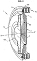
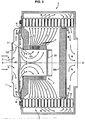
figure 1 est une vue de face, en coupe axiale, d'un appareil de chauffage équipé d'une porte qui fait l'objet d'un premier mode de réalisation de l'invention, dans lequel le brûleur intégré à la porte est plat; - la
figure 2 représente la même porte en perspective, également coupée ; - la
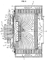
figure 3 est une vue analogue à celle de lafigure 1 , montrant un deuxième mode de réalisation de l'invention, dans lequel le brûleur intégré à la porte est cylindrique ; - la
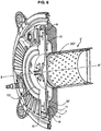
figure 4 est une vue analogue à celle de lafigure 1 , montrant un troisième mode de réalisation de l'invention, dans lequel la porte est équipée d'un moto-ventilateur ; - la
figure 5 représente la même porte en perspective, également coupée ; - la
figure 6 est une vue en perspective, coupée, montrant une variante de réalisation de l'invention, dans laquelle le plateau déflecteur qui équipe la porte présente une portion en saillie ; - la
figure 7 est une vue en perspective qui montre la tôle intérieure et le plateau déflecteur de la porte représentée sur lafigure 6 .
- the
figure 1 is a front view, in axial section, of a heating device equipped with a door which is the subject of a first embodiment of the invention, in which the burner integrated in the door is flat; - the
figure 2 represents the same perspective door, also cut; - the
figure 3 is a view similar to that of thefigure 1 , showing a second embodiment of the invention, in which the burner integrated in the door is cylindrical; - the
figure 4 is a view similar to that of thefigure 1 , showing a third embodiment of the invention, wherein the door is equipped with a motor fan; - the
figure 5 represents the same perspective door, also cut; - the
figure 6 is a perspective view, cut away, showing an alternative embodiment of the invention, wherein the deflector plate which equips the door has a projecting portion; - the
figure 7 is a perspective view that shows the inner plate and the baffle plate of the door shown on thefigure 6 .
Sur les
Les mêmes chiffres et lettres de référence ont été utilisés dans un but de bonne clarté afin de désigner des éléments identiques ou similaires des différents modes de réalisation représentés.The same numbers and reference letters have been used for purposes of clarity in order to designate identical or similar elements of the various embodiments shown.
Sur les
Celle-ci peut s'adapter à différents types d'appareils de chauffage.It can adapt to different types of heaters.
Sur les modes de réalisation illustrés, il s'agit -à simple titre d'exemple- d'un échangeur de chaleur à condensation du genre produit par la Société GIANNONI FRANCE sous la dénomination « ISOTHERMIC » (marque déposée).In the illustrated embodiments, this is merely an example of a condensing heat exchanger of the type produced by GIANNONI FRANCE under the name "ISOTHERMIC" (registered trademark).
Ce type d'échangeur comporte deux faisceaux de tubes hélicoïdaux montés coaxialement à l'intérieur d'une enveloppe étanche aux gaz, séparés par une cloison en matériau thermiquement isolant. Les tubes sont parcourus par le fluide à chauffer, de l'eau par exemple. Ils ont une section aplatie ovalisée et l'interstice entre spires est calibré et de faible largeur. Le brûleur est situé à l'intérieur de l'un des faisceaux, dit primaire, et les gaz chauds issus du brûleur traversent ces interstices de l'intérieur vers l'extérieur, avec un coefficient d'échange thermique élevé. Ils contournent ensuite la cloison isolante et traversent les interstices de l'autre faisceau, dit secondaire, en sens contraire (de l'extérieur vers l'intérieur), avant d'être évacués hors de l'enveloppe par un conduit ou une manchette approprié.This type of exchanger comprises two bundles of helical tubes coaxially mounted inside a gas-tight envelope, separated by a partition of thermally insulating material. The tubes are traversed by the fluid to be heated, water for example. They have an oval flattened section and the interstice between turns is calibrated and of small width. The burner is located inside one of the beams, said primary, and the hot gases from the burner through these interstices from the inside to the outside, with a high heat exchange coefficient. They then bypass the insulating partition and cross the interstices of the other beam, said secondary, in the opposite direction (from the outside towards the inside), before being evacuated out of the envelope by a conduit or a suitable cuff. .
Un tel appareil, bien connu, ne sera pas décrit en détail ci-après afin de ne pas alourdir inutilement la présente description.Such a device, well known, will not be described in detail below so as not to unnecessarily burden this description.
Cependant, si nécessaire, le lecteur pourra se reporter aux documents de brevet suivants, qui se rapportent à un échangeur de ce type :
La porte 1 est fixée dans l'encadrement 61 de la paroi de façade d'un appareil de chauffage AC dont la coque 6 présente une paroi latérale 60 et une paroi de fond 62 présentant une manchette d'échappement 620 destinée à être connectée à un conduit (non représenté) d'évacuation des gaz brûlés. Cette coque 6 contient un enroulement hélicoïdal tubulaire en acier inoxydable 7, de section aplatie et ovale, d'axe X-X'. Il est composé d'un faisceau primaire 70 et d'un faisceau secondaire 71, séparés par un disque isolant 600. Il s'agit d'un échangeur de chaleur à condensation, du même type que ceux décrits dans les documents précités, apte à chauffer de l'eau ou tout autre fluide, que l'on fait circuler dans l'enroulement 7.The
La porte 1 a une forme générale circulaire, centrée sur l'axe X-X' et possède des organes de fixation périphériques (non représentés) permettant de la monter de manière amovible sur la façade de l'appareil, par exemple à l'aide de quatre oreilles disposées à 90°, et vissées à la façade.The
La porte 1 comprend une paire de parois de fine épaisseur, l'une extérieure 10, l'autre intérieure 11. Ces parois sont en tôle d'acier inoxydable découpée et emboutie.The
Elles sont fixées l'une à l'autre à leur périphérie, par sertissage et/ou soudage ; ce rebord périphérique 100 présente une cavité annulaire, tournée vers l'intérieur, qui reçoit un joint d'étanchéité 101 apte à s'appliquer, lorsque la porte est fermée, contre une collerette d'appui 72 fixée dans l'encadrement 61 et en contact, par sa face interne, contre la première spire de l'enroulement 7.They are fixed to one another at their periphery, by crimping and / or welding; this
L'embouti de la tôle extérieure 10 est tel qu'elle présente une convexité dirigée vers l'extérieur, dont la zone centrale est percée d'une ouverture circulaire 102 centrée sur X-X'. La paroi bordant cette ouverture possède un profil adapté pour le montage et la fixation étanche -par exemple au moyen de vis ou par soudage- d'une manchette 5 (représentée en traits interrompus) d'amenée du mélange gazeux combustible dans l'appareil via un conduit approprié 50.The stamping of the
L'embouti de la tôle intérieure 11 est tel qu'elle présente une convexité dirigée vers l'intérieur, dont la zone centrale est percée d'une ouverture circulaire 103 centrée sur X-X'. Cette ouverture est bordée par une embouchure annulaire sur laquelle est fixé le brûleur 2. Ce dernier a la forme d'une coupelle cylindrique de faible hauteur, dont la partie annulaire 20 est emmanchée et retenue par serrage (emmanchement à force) et/ou par quelques points de soudure, sur ladite embouchure, tandis que son fond plat 21 est perforé, constituant la surface de combustion. Dans le mode de réalisation illustré, le brûleur a une structure composite, comprenant une tôle intérieure emboutie perforée et une paroi extérieure fibreuse et poreuse permettant un bon accrochage de la flamme.The stamping of the
Différentes structures (à simple paroi ou double-paroi notamment) et différentes formes de brûleur peuvent être prévues.Different structures (single wall or double wall in particular) and different forms of burner can be provided.
Ainsi, le fond 21 faisant office de surface de combustion pourrait être légèrement bombé, avec sa convexité tournée vers l'intérieur de l'appareil, et son centre de courbure centré sur X-X'. Cette forme galbée permet de bien absorber les phénomènes de dilatation, la surface de combustion pouvant se déformer naturellement pour prendre une courbure plus ou moins prononcée en fonction de cette dilatation.Thus, the bottom 21 acting as a combustion surface could be slightly curved, with its convexity turned towards the inside of the apparatus, and its center of curvature centered on X-X '. This curved shape allows the dilation phenomena to be well absorbed, the combustion surface being able to deform naturally to take a more or less pronounced curvature depending on this expansion.
Compte-tenu de ces formes embouties « creuses », un espace libre est disponible entre les deux tôles 10 et 11.Given these forms stamped "hollow", a free space is available between the two
Dans cet espace est logé un plateau discoïde 3 de faible épaisseur, centré sur X-X'. Son diamètre est sensiblement plus grand que celui des ouvertures 102 et 103 ; il est néanmoins légèrement inférieur à celui dudit espace libre.In this space is housed a
Le plateau 3 est constitué de deux parois minces 30, 31, par exemple en tôle d'acier inoxydable, fixées l'une à l'autre à leur périphérie 300 de manière étanche, par exemple par sertissage et/ou soudage. La tôle extérieure 30 est plane ; la tôle intérieure 31 présente une zone principale annulaire également plane, parallèle à la tôle 30, et une zone centrale 310 légèrement bombée, avec une convexité tournée vers l'intérieur (côté brûleur).The
Entre les parois 30 et 31 est encapsulé un matériau isolant 32, par exemple un gaz neutre tel que de l'azote ou une matière solide à base de céramique. Sa fonction est de limiter le transfert de chaleur entre les deux parois.Between the
La paroi intérieure 31 est pourvue à sa périphérie de plusieurs bossages, tels que des emboutis 311, régulièrement répartis (par exemple six bossages à 60° d'angle) par l'intermédiaire desquels elle est fixée à la tôle 11.The
Cette fixation est réalisée par exemple par des points de soudure, en des zones d'aire restreinte, quasi-ponctuelles, afin de limiter le transfert de chaleur entre les deux parois 11 et 31, et aussi de ne pas contrarier le passage du gaz entre ces dernières. Ces bossages font ainsi aussi office d'entretoises.This fixing is carried out for example by soldering points, in zones of restricted area, quasi-point, in order to limit the transfer of heat between the two
La porte 1 comporte, côté intérieur, une garniture annulaire 4 en matière thermiquement isolante, et résistant à la chaleur, par exemple en céramique ou en matériau à base de céramique. Cette garniture est emmanchée axialement par son ouverture centrale sur la partie cylindrique 20 du brûleur 2 et est retenue contre la face interne de la paroi 11 par un rebord interne de forme appropriée 720 de la collerette d'appui 72. Ainsi, la garniture annulaire 4 recouvre la paroi 11 en périphérie du brûleur, jusqu'au niveau de l'enroulement 7, constituant un écran thermique au regard des gaz très chauds issus du brûleur présents à l'intérieur du faisceau primaire de l'échangeur.The
Le brûleur ayant été allumé, au moyen d'un système d'allumage approprié (non représenté), et le mélange combustible air/carburant gazeux étant amené dans la manchette 5 via le conduit 50, l'appareil fonctionne de la manière expliquée ci-après.The burner having been ignited, by means of a suitable ignition system (not shown), and the gaseous air / fuel fuel mixture being fed into the
Le flux de gaz qui rentre dans l'appareil traverse l'ouverture 102 (flèches F), rencontre la paroi plane 30 du plateau 3 qui lui fait face, et est éclaté en une multitude de courants gazeux qui se trouvent déviés à angle droit et qui s'écoulent radialement, de l'axe X-X' vers l'extérieur du disque, jusqu'au bord périphérique 300 (flèches G), tout en léchant la paroi 30 ; arrivés au-delà du bord 300, ils contournent celui-ci (flèches H) et s'écoulent en sens contraire, en direction de l'axe X-X', vers l'ouverture de sortie 103, en léchant cette fois la paroi 31 (flèches I) pour enfin pénétrer à l'intérieur du brûleur 2.The flow of gas which enters the apparatus passes through the opening 102 (arrows F), meets the
La combustion, visualisée par des dards d, génère des gaz brûlés très chauds (flèches J), dont la température est de l'ordre de 950 à 1000°C ;The combustion, visualized by darts d, generates very hot burnt gases (arrows J), whose temperature is of the order of 950 to 1000 ° C;
Ces gaz traversent les interstices entre spires du faisceau primaire 70 radialement de l'intérieur vers l'extérieur, ressortent de celui-ci (flèches K), sont canalisés à l'intérieur de la coque 6, pénètrent dans les interstices entre spires du faisceau secondaire 71 (flèches L), qu'ils traversent radialement de l'extérieur vers l'intérieur, ressortent de celui-ci (flèches M), et sont évacués par la manchette 620 (flèches N).These gases pass through the interstices between turns of the
Le fluide circulant à l'intérieur de l'enroulement est d'abord préchauffé dans le faisceau secondaire 71, puis chauffé dans le faisceau primaire 70, comme cela est bien connu.The fluid circulating inside the winding is first preheated in the
Lorsque l'appareil est en fonctionnement, la tôle intérieure 31 du plateau déflecteur 3 se trouve à une température sensiblement plus élevée que sa tôle extérieure 30. De plus, cette température varie de manière relativement importante, et fréquemment, lors des phases de mise en route et d'arrêt de l'appareil.When the apparatus is in operation, the
Il en résulte des dilatations et des rétractions successives de cette paroi, plus élevées que celles de la paroi extérieure, sources de contraintes mécaniques susceptibles à terme d'altérer la liaison périphérique des deux parois. Cependant, ce risque est éliminé grâce à la présence du bombé central 310 qui peut se déformer élastiquement, de manière réversible, en absorbant ces contraintes, de sorte que celles-ci ne se répercutent pas au niveau du rebord de jonction périphérique 300.This results in successive expansions and retractions of this wall, which are higher than those of the outer wall, sources of mechanical stresses likely to alter the peripheral connection of the two walls. However, this risk is eliminated thanks to the presence of the
Grâce à la présence du plateau déflecteur 3, les déperditions calorifiques de l'appareil vers l'extérieur sont extrêmement faibles.Due to the presence of the
En effet, d'une part, seule une faible partie de la chaleur diffusée par la tôle 11 est transmise à ce plateau 3 et, d'autre part, la quasi-totalité de la chaleur émise en façade est récupérée par le mélange gazeux rentrant, qui lèche les parois chaudes au cours de sa trajectoire en chicane. De surcroît, ce préchauffage améliore la qualité de la combustion.Indeed, on the one hand, only a small part of the heat diffused by the
A titre indicatif, si le mélange gazeux délivré par la manchette 5 se trouve à une température de l'ordre de 20 à 25°C, la température de la paroi extérieure 10 de la porte est de l'ordre de 25 à 30°C, nettement inférieure par conséquent à la température à laquelle se verrait portée la paroi externe d'une porte traditionnelle, température qui correspondrait à la température extérieure de la paroi 11 si celle-ci n'était pas refroidie par le mélange gazeux entrant, à savoir entre 120 et 180°C environ.As an indication, if the gaseous mixture delivered by the
Tout risque de brûlure d'un opérateur se trouve de ce fait exclu.Any risk of burning an operator is therefore excluded.
La
Il s'agit ici d'un brûleur cylindrique 2', d'axe X-X', fermé par un fond plat 20' et dont l'entrée présente un rebord en forme de collerette 21' qui entoure l'ouverture centrale 103 de la tôle interne 11 et est fixée à cette dernière, par exemple par quelques points de soudure.This is a cylindrical burner 2 ', of axis X-X', closed by a flat bottom 20 'and whose inlet has a flange-like rim 21' which surrounds the
Le fonctionnement de l'appareil est analogue à celui précédemment décrit.The operation of the apparatus is similar to that previously described.
Les
Celui-ci comprend un stator annulaire 80 qui est fixé à la tôle extérieure 10 au moyen de pattes d'attache appropriées, non représentées.This comprises an
Il comporte une série de pales 82 portées par un disque rotatif 83 qui est fixé à son rotor 81 à l'aide de vis 810. Ces pales sont logées dans un renfoncement circulaire, de forme adaptée, formé dans la paroi de la tôle extérieure 10, qui fait ainsi office de carter pour ces dernières.It comprises a series of
Le disque porte-pales 83 s'étend dans un plan général perpendiculaire à l'axe X-X', tout près de la face externe du plateau déflecteur 3. Les pales 82 sont fixées sur la face externe du disque 83.The
Le stator 80 du moto-ventilateur est positionné avec un certain jeu (espace annulaire) à l'intérieur de l'ouverture d'entrée 102 de la tôle extérieure 10. Cette ouverture a la forme d'une embouchure entourée d'un collecteur annulaire 9 (approximativement torique) centré sur l'axe X-X'. Ce collecteur peut être rapporté ou former partie intégrante de la tôle 10.The
Le collecteur 9 est connecté à un conduit 91 d'amenée d'un comburant gazeux, tel que du butane ou du propane par exemple. Sa paroi annulaire interne et/ou celle de l'embouchure qu'il entoure est percée d'une pluralité d'orifices 90 régulièrement répartis à sa périphérie, permettant de diffuser le comburant gazeux sous forme de jets dans l'interstice annulaire entourant le stator.The
En fonctionnement, le rotor étant en rotation, le comburant gazeux passe dans le conduit 91 (flèche C), arrive dans le collecteur annulaire 9 (flèches D), sort par les orifices 90 et se trouve aspiré à l'intérieur de l'appareil par les pales 82 en mouvement (flèches F). Ces dernières aspirent également de l'air ambiant (carburant) qui est prélevé à l'extérieur (flèches E) et passe dans le même interstice annulaire, en se mélangeant au gaz issu des orifices 90.In operation, the rotor being rotated, the gaseous oxidant passes through the conduit 91 (arrow C), arrives in the annular collector 9 (arrows D), leaves through the
C'est donc un pré-mélange gazeux combustible qui est pulsé à l'intérieur de la porte 1 par le moto-ventilateur 8.It is therefore a combustible gas premix that is pulsed inside the
Celui-ci suit un trajet analogue à celui déjà décrit ci-dessus, en référence à la
Selon le mode de réalisation, les courants gazeux sortant de l'embouchure d'entrée 102 ne lèchent pas à proprement parler la face externe du plateau 3. Cependant l'effet est similaire. Le plateau 3 fait office de bouclier thermique ; comme il n'est pas en contact avec le disque rotatif 83, il n'y a pas de transmission de chaleur entre ces deux éléments, ce qui met le moto-ventilateur à l'abri des élévations de température.According to the embodiment, the gas streams leaving the
Il est bien évidemment possible d'équiper d'un moto-ventilateur de ce genre une porte pourvue d'un brûleur cylindrique, comme celle de la
Les
Cette tôle extérieure, référencée 30', présente une zone principale annulaire plane, parallèle à la tôle intérieure 31 et une zone centrale 301' en saillie, en forme de téton, dont la pointe est tournée vers l'ouverture d'entrée 102 de la porte 1.This outer sheet, referenced 30 ', has a flat annular main zone, parallel to the
Cette forme est obtenue par exemple par emboutissage.This form is obtained for example by stamping.
Le téton 301' améliore la répartition radiale du flux d'air entrant, comme représenté par les flèches P. The stud 301 'improves the radial distribution of the incoming airflow, as represented by the arrows P.
En outre, ceci réduit les pertes de charge par rapport à une surface plane.In addition, this reduces the pressure losses with respect to a flat surface.
Grâce à cette forme particulière de la zone centrale 301', le ventilateur qui amène le mélange combustible air/carburant gazeux, dans la manchette 5, est moins sollicité et peut tourner moins vite pour obtenir un même débit.Thanks to this particular form of the central zone 301 ', the fan which brings the air fuel / gas fuel mixture into the
La
Bien que cela ne soit pas représenté, il peut en être de même pour le plateau déflecteur 3 décrit précédemment.Although this is not shown, it may be the same for the
Claims (15)
- A door with a built-in burner for a heating appliance, which is provided on its internal face with a gas burner (2; 2') and on its external face with a system (5; 8-9) for feeding a combustible gas mixture to the burner, this door (1) being adapted so as to be able to be engaged into the frame (61) of a wall of the appliance, and in order to be removably attached to this frame, and including a pair of metal sheets (10, 11) firmly attached to each other at their periphery (100), the outer metal sheet (10) having in its central zone an inlet opening (102) for the arrival of said gas mixture while the inner metal sheet (11) has in its central zone an outlet opening (103) coaxial with said inlet opening (102), to which is attached the burner (2;2'), both of these sheets (10, 11) are spaced apart from each other, making between them a space, inside which a deflector plate (3, 3') is fixedly mounted, this deflector plate (3, 3') having the shape of a disc, the diameter of which is substantially greater than that of said inlet (102) and outlet (103) openings of said door, and being mounted centered on the axis (X-X') of these openings and perpendicular to the latter, said door being characterized by the fact that this deflector plate (3, 3') consists of two slightly spaced apart parallel metal sheets (30, 30', 31), attached to each other at their periphery (300), this deflector plate (3, 3') thus being shaped and dimensioned so that the gas mixture flow penetrating into the appliance through said inlet opening (102) is deflected towards the outside of the deflector plate (3, 3'), circumvents the peripheral edge (300) thereof from the outside towards the inside, and then flows onto its internal face, in order to flow out through said outlet opening (103) and penetrate into the burner (2; 2').
- The door with a built-in burner according to claim 1, characterized by the fact that said inlet (102) and outlet (103) openings are circular.
- The door with a built-in burner according to claim 1 or claim 2, characterized by the fact that said deflector plate (3, 3') has, on the peripheral border portion of its internal face, pads or bosses (311) via which this face is applied and attached against the external face of said inner metal sheet (11), this through quasi point-like contact zones, which do not impede the passage of the gas mixture, while limiting heat transmission from the inner metal sheet (11) to the deflector plate (3).
- The door with a built-in burner according to any of the preceding claims, characterized by the fact that said deflector plate (3, 3') is provided with a heat insulator (32) inserted between said metal sheets (30, 31), this insulator consisting in a neutral gas, such as nitrogen for example, or in a solid material, for example based on ceramic.
- The door with a built-in burner according to any of the preceding claims, characterized by the fact that the constitutive inner metal sheet (31) of said deflector plate (3, 3') has a bulging central portion (310) which allows its elastic deformation and allows it to absorb the stresses generated by the expansions and contractions related to changes in temperature, depending on whether the appliance is operating or is stopped.
- The door with a built-in burner according to any of the preceding claims characterized by the fact that the constitutive outer sheet (30') of said deflector plate (3') has a nipple-shaped central portion (301'), the tip of which is turned towards the inlet opening (102), this nipple promoting the radial distribution of the flow of the gas mixture penetrating through said inlet opening.
- The door with a built-in burner according to any of the preceding claims, characterized by the fact that said burner (2) is flat, its combustion surface being perpendicular to the axis (X-X') of said openings.
- The door with a built-in burner according to any of the claims 1 to 6, characterized by the fact that said burner is slightly bulging and its combustion surface is convex, centered on the axis (X-X') of said openings.
- The door with a built-in burner according to any of claims 1 to 6, characterized by the fact that said burner (2, 2') is annular, its cylindrical combustion surface being centered on the axis (X-X') of said openings.
- The door with a built-in burner according to any of the preceding claims, characterized by the fact that the zone of the inner metal sheet (11) which surrounds the outlet opening is lined, on its internal face with a heat resistant and thermally insulating material (4), such as a material in ceramic or based on ceramic.
- The door with a built-in burner according to any of the preceding claims, characterized by the fact that it is provided on its internal face with a peripheral seal gasket (101) capable of being applied against the external face of a collar (72) firmly attached to said wall frame (61).
- The door with a built-in burner according to any of the preceding claims, characterized by the fact that the system for feeding the combustible gas mixture comprises a sleeve (5) mounted at the inlet opening (102) of said outer metal sheet (10) and attached to the latter.
- The door with a built-in burner according to any of claims 1 to 11, characterized by the fact that it is equipped with an electric motor fan (8) which is firmly attached to said outer sheet (10) and is adapted so as to suck in the gas mixture through said inlet opening (102) and to discharge it towards the burner (2; 2').
- The door with a built-in burner according to claim 13, characterized by the fact that said motor fan (8) is of the centrifugal type and has a series of rotary vanes (82) which are housed in a wall recess of said outer metal sheet (10), which acts as a case, and extend in proximity to the external face of the deflector plate (3).
- The door with a built-in burner according to claim 14, characterized by the fact that the stator (80) of said motor fan (8) is positioned inside said inlet opening (102) of said outer metal sheet (10) on the one hand and the system for feeding the combustible gas mixture comprises an annular collector (9) mounted at this inlet opening (102) and attached to the outer metal sheet (10), on the other hand, thereby surrounding the stator (80) of said motor fan, this collector (9) being fed with gas fuel through a conduit (91) and its wall being pierced with a plurality of radial orifices (90) through which the gas fuel is diffused into the annular interstice separating the stator (80) from the edge of the inlet opening (102), so as to then be sucked in by said rotating vanes (82), at the same time as ambient air (oxidizer) is sucked in via this same annular interstice.
Applications Claiming Priority (2)
| Application Number | Priority Date | Filing Date | Title |
|---|---|---|---|
| FR0951422A FR2942866B1 (en) | 2009-03-06 | 2009-03-06 | INTEGRATED BURNER DOOR FOR HEATING APPARATUS |
| PCT/EP2010/051126 WO2010100004A1 (en) | 2009-03-06 | 2010-01-29 | Door with a built-in burner for a heating appliance |
Publications (2)
| Publication Number | Publication Date |
|---|---|
| EP2404112A1 EP2404112A1 (en) | 2012-01-11 |
| EP2404112B1 true EP2404112B1 (en) | 2016-06-29 |
Family
ID=41151784
Family Applications (1)
| Application Number | Title | Priority Date | Filing Date |
|---|---|---|---|
| EP10701549.7A Active EP2404112B1 (en) | 2009-03-06 | 2010-01-29 | Door with a built-in burner for a heating appliance |
Country Status (9)
| Country | Link |
|---|---|
| US (2) | US8978638B2 (en) |
| EP (1) | EP2404112B1 (en) |
| JP (1) | JP5342023B2 (en) |
| KR (1) | KR101534894B1 (en) |
| CN (1) | CN102341651B (en) |
| CA (1) | CA2752093C (en) |
| FR (1) | FR2942866B1 (en) |
| RU (1) | RU2484376C1 (en) |
| WO (1) | WO2010100004A1 (en) |
Families Citing this family (27)
| Publication number | Priority date | Publication date | Assignee | Title |
|---|---|---|---|---|
| FR2955929B1 (en) | 2010-02-01 | 2014-04-18 | Mer Joseph Le | CONDENSED HEAT EXCHANGER FOR MULTIPLE FLUIDS AND DEVICE FOR PRODUCING HOT FLUIDS COMPRISING SUCH AN EXCHANGER |
| FR2972789B1 (en) | 2011-03-14 | 2013-04-12 | Giannoni France | CONDENSING GAS HEATING APPARATUS |
| CN102563663A (en) * | 2012-02-02 | 2012-07-11 | 安徽盛运机械股份有限公司 | Special fire view door of garbage incinerator |
| EP3139106B1 (en) * | 2014-03-17 | 2018-12-26 | Condevo S.p.A. | Heat exchange cell and method |
| KR101594940B1 (en) * | 2014-03-18 | 2016-02-17 | 주식회사 경동나비엔 | Heat exchanger |
| KR101597980B1 (en) * | 2014-03-18 | 2016-02-29 | 주식회사 경동나비엔 | Heat exchanger and method of the unit plate comprising the heat exchanger |
| GB2525873A (en) * | 2014-05-07 | 2015-11-11 | Worgas Burners Ltd | Gas burner |
| EP3018408B1 (en) * | 2014-11-05 | 2017-06-07 | WORGAS BRUCIATORI S.r.l. | Burner |
| US9631808B2 (en) * | 2014-11-21 | 2017-04-25 | Honeywell International Inc. | Fuel-air-flue gas burner |
| FR3047063B1 (en) * | 2016-01-22 | 2018-11-30 | Sermeta | THERMAL EXCHANGING DEVICE FOR CONDENSED HEAT EXCHANGER |
| FR3047549B1 (en) * | 2016-02-09 | 2019-05-10 | Sermeta | DEFLECTOR FOR CONDENSED HEAT EXCHANGER AND EXCHANGER PROVIDED WITH SUCH DEFLECTOR |
| NL2016755B1 (en) * | 2016-05-10 | 2017-11-16 | Remeha B V | Heat exchanger. |
| US10627113B2 (en) * | 2016-12-29 | 2020-04-21 | Whirlpool Corporation | Distributed vertical flame burner |
| FR3062471B1 (en) * | 2017-01-27 | 2019-06-07 | Sermeta | HEAT EXCHANGER |
| JP6834772B2 (en) * | 2017-05-22 | 2021-02-24 | 株式会社ノーリツ | Hot water device |
| US10753644B2 (en) | 2017-08-04 | 2020-08-25 | A. O. Smith Corporation | Water heater |
| IT201700096656A1 (en) * | 2017-08-28 | 2019-02-28 | Cosmogas Srl | HEAT EXCHANGER FOR A BOILER, AND HEAT EXCHANGER TUBE |
| DE102018102967A1 (en) * | 2018-02-09 | 2019-08-14 | Vaillant Gmbh | Heat cell with metallic insulating ring |
| DE102018102935A1 (en) | 2018-02-09 | 2019-08-14 | Vaillant Gmbh | Heat cell with cooled burner door |
| IT201800003438A1 (en) * | 2018-03-12 | 2019-09-12 | Athena S P A | IMPROVED BOILER |
| IT201800003451A1 (en) * | 2018-03-12 | 2019-09-12 | Condevo S P A | LOCKING DOOR FOR HEAT EXCHANGE CELL FOR BOILER |
| US11162710B2 (en) * | 2018-06-08 | 2021-11-02 | Intellihot, Inc. | Heat exchanger including flue flow path guide system |
| DE102018113993A1 (en) * | 2018-06-12 | 2019-12-12 | Vaillant Gmbh | Heat cell of a heater |
| FR3125326B1 (en) | 2021-07-16 | 2023-07-14 | Sermeta | Heat exchanger |
| FR3125327B1 (en) * | 2021-07-16 | 2023-09-29 | Sermeta | Condensing heat exchanger. |
| CN113819650A (en) * | 2021-07-29 | 2021-12-21 | 浙江菲斯曼供热技术有限公司 | Heating device |
| WO2023028129A1 (en) * | 2021-08-25 | 2023-03-02 | Fulton Group N.A., Inc. | Compact flat plate premix fuel combustion system, and fluid heating system and packaged burner system including the same |
Family Cites Families (26)
| Publication number | Priority date | Publication date | Assignee | Title |
|---|---|---|---|---|
| DE206577C (en) * | ||||
| FR362304A (en) | 1906-01-10 | 1906-06-19 | Ferdinand Toth | Fireplace door with drawer for air intake adjustment |
| FR429885A (en) | 1911-05-17 | 1911-10-03 | Leonhardt & Merkle | Fireplace door with installation for pre-heating the secondary air |
| US1777065A (en) * | 1927-12-05 | 1930-09-30 | Milton M Yale | Air preheater |
| US1766191A (en) * | 1929-05-16 | 1930-06-24 | Nelson J Russell | Fuel-saving device |
| GB959310A (en) * | 1961-12-01 | 1964-05-27 | Vauxhall Boiler Company Ltd | Improvements in and relating to furnace doors |
| US3614388A (en) * | 1970-06-22 | 1971-10-19 | Aubrey C Robinson | Electric heating oven system |
| US4871014A (en) * | 1983-03-28 | 1989-10-03 | Tui Industries | Shell and tube heat exchanger |
| FR2553869B1 (en) * | 1983-10-21 | 1988-01-08 | Lemer Joseph | CONDENSING BOILER FOR HEATER WITH HEAT FLUID |
| AT388988B (en) * | 1987-01-23 | 1989-09-25 | Vaillant Gmbh | BOILER WITH FAN BURNER FASTENED IN AN OPENING |
| FR2700608B1 (en) | 1993-01-15 | 1995-04-07 | Joseph Le Mer | Heat exchanger element, method and device for manufacturing it. |
| ATE183300T1 (en) * | 1993-12-06 | 1999-08-15 | Papst Motoren Gmbh & Co Kg | BURNER FAN FOR GAS PREMIX BURNERS |
| JP3001398B2 (en) * | 1995-04-11 | 2000-01-24 | 株式会社サムソン | Combustion failure detection device for surface combustion burner |
| JP3540486B2 (en) * | 1996-02-02 | 2004-07-07 | 三洋電機株式会社 | Liquid fuel combustion device |
| RU2090804C1 (en) * | 1996-04-22 | 1997-09-20 | Рафаэл Газетов | Generator heat utilizer |
| FR2794521B1 (en) * | 1999-06-04 | 2001-07-13 | Geminox | FORCED VENTILATION GAS BURNER FOR BOILER |
| CA2300839A1 (en) * | 2000-03-17 | 2001-09-17 | Asea Brown Boveri Inc. | Thermal equalizer |
| DE10051307B4 (en) * | 2000-10-17 | 2008-07-31 | Robert Bosch Gmbh | Apparatus for separating gas and liquid solid particles from a gas-liquid-solid particle mixture flowing in a conduit and methods for separating same |
| FR2835042B1 (en) * | 2002-01-22 | 2004-12-17 | Mer Joseph Le | GAS BURNER, FACING BIPARTITE COMBUSTION AND BOILER EQUIPPED WITH SUCH A BURNER |
| US6908201B2 (en) | 2002-06-28 | 2005-06-21 | Silicon Light Machines Corporation | Micro-support structures |
| FR2846075B1 (en) * | 2002-10-16 | 2005-03-04 | Realisation Mecaniques Engenee | HEAT EXCHANGER WITH CONDENSATION, PLASTIC ENVELOPE |
| EP1561075B1 (en) * | 2002-10-16 | 2013-05-01 | Giannoni France | Condensation heat exchanger with plastic casing |
| FR2854229A1 (en) * | 2003-04-25 | 2004-10-29 | Realisation Mecaniques Engenee | Heat exchanger for use in gas boiler, has primary and secondary heat exchanger arranged to transverse flow of hot air towards interstice of exchangers, and duct passing another flow of hot air into secondary exchanger |
| DE102004005048A1 (en) * | 2004-01-30 | 2005-09-01 | Viessmann Werke Gmbh & Co Kg | heater |
| ATE392536T1 (en) * | 2004-04-23 | 2008-05-15 | Shell Int Research | PREVENTING SCABING EFFECTS IN DRILL HOLES |
| GB0522309D0 (en) | 2005-11-01 | 2005-12-07 | Microgen Energy Ltd | An annular burner assembly |
-
2009
- 2009-03-06 FR FR0951422A patent/FR2942866B1/en active Active
-
2010
- 2010-01-29 EP EP10701549.7A patent/EP2404112B1/en active Active
- 2010-01-29 RU RU2011140497/06A patent/RU2484376C1/en active
- 2010-01-29 US US13/254,593 patent/US8978638B2/en active Active
- 2010-01-29 KR KR1020117020721A patent/KR101534894B1/en active IP Right Grant
- 2010-01-29 CN CN201080009922.9A patent/CN102341651B/en active Active
- 2010-01-29 CA CA2752093A patent/CA2752093C/en active Active
- 2010-01-29 JP JP2011552372A patent/JP5342023B2/en active Active
- 2010-01-29 WO PCT/EP2010/051126 patent/WO2010100004A1/en active Application Filing
-
2015
- 2015-02-10 US US14/618,308 patent/US9816726B2/en active Active
Also Published As
| Publication number | Publication date |
|---|---|
| FR2942866B1 (en) | 2012-03-23 |
| US20150153067A1 (en) | 2015-06-04 |
| US9816726B2 (en) | 2017-11-14 |
| KR101534894B1 (en) | 2015-07-07 |
| KR20110136802A (en) | 2011-12-21 |
| FR2942866A1 (en) | 2010-09-10 |
| US8978638B2 (en) | 2015-03-17 |
| CN102341651A (en) | 2012-02-01 |
| US20120000456A1 (en) | 2012-01-05 |
| JP5342023B2 (en) | 2013-11-13 |
| RU2484376C1 (en) | 2013-06-10 |
| JP2012519823A (en) | 2012-08-30 |
| CN102341651B (en) | 2014-05-07 |
| CA2752093A1 (en) | 2010-09-10 |
| RU2011140497A (en) | 2013-04-20 |
| CA2752093C (en) | 2016-06-14 |
| EP2404112A1 (en) | 2012-01-11 |
| WO2010100004A1 (en) | 2010-09-10 |
Similar Documents
| Publication | Publication Date | Title |
|---|---|---|
| EP2404112B1 (en) | Door with a built-in burner for a heating appliance | |
| EP0520913B1 (en) | Heating device with catalytic burner | |
| EP1618341B1 (en) | Condensation heat exchanger | |
| EP2540162A1 (en) | Apparatus, assembly and method for manual and localised weeding | |
| EP3026348B1 (en) | Gas cooking appliance, especially a gas oven | |
| FR2684747A3 (en) | Gas burner of the type with spray pipes | |
| CA1123285A (en) | Combustion process for liquid fuel and burner for its use | |
| FR2780770A1 (en) | RECOVERY DEVICE, RECOVERY APPARATUS FOR BURNER WITH RADIANT TUBE AND DEFLECTOR | |
| EP0679839A1 (en) | Improvements to gas burners | |
| FR2699993A1 (en) | Apparatus for drying web materials such as paper for example | |
| EP0651203B1 (en) | Radiant gas burner for stove or cooker hob | |
| EP0486741A1 (en) | Gas heating apparatus by infrared radiation | |
| EP4048953B1 (en) | Fireplace with suspended hearth | |
| EP2166285B1 (en) | Mischer für Kessel | |
| FR2745891A1 (en) | Atmospheric gas burner | |
| EP0660040A1 (en) | Burner head for burner with low pollutants emission and boiler provided with such a burner | |
| FR2678356A1 (en) | Catalytic burner with air sucked in | |
| EP1363072A1 (en) | Burner head for gas cooking apparatus | |
| EP0549416A1 (en) | Grid burner and heating installation comprising same | |
| FR2688298A1 (en) | Hot-air generating apparatus with a catalytic panel in a combustion chamber | |
| BE488716A (en) | ||
| FR2606494A3 (en) | Heating boiler, especially for operating at low temperature | |
| BE479490A (en) | ||
| BE664471A (en) | ||
| FR2893388A3 (en) | Burner e.g. gas solder burner has chamber, which is supplied with gas through hole in head, such that gas can burn in chamber and element can be heated up and can be soldered whereby chamber is formed by head and element |
Legal Events
| Date | Code | Title | Description |
|---|---|---|---|
| PUAI | Public reference made under article 153(3) epc to a published international application that has entered the european phase |
Free format text: ORIGINAL CODE: 0009012 |
|
| 17P | Request for examination filed |
Effective date: 20110728 |
|
| AK | Designated contracting states |
Kind code of ref document: A1 Designated state(s): AT BE BG CH CY CZ DE DK EE ES FI FR GB GR HR HU IE IS IT LI LT LU LV MC MK MT NL NO PL PT RO SE SI SK SM TR |
|
| DAX | Request for extension of the european patent (deleted) | ||
| RAP1 | Party data changed (applicant data changed or rights of an application transferred) |
Owner name: SERMETA |
|
| 111Z | Information provided on other rights and legal means of execution |
Free format text: AT BE BG CH CY CZ DE DK EE ES FI FR GB GR HR HU IE IS IT LT LU LV MC MK MT NL NO PL PT RO SE SI SK SM TR Effective date: 20140909 |
|
| GRAP | Despatch of communication of intention to grant a patent |
Free format text: ORIGINAL CODE: EPIDOSNIGR1 |
|
| INTG | Intention to grant announced |
Effective date: 20160302 |
|
| GRAS | Grant fee paid |
Free format text: ORIGINAL CODE: EPIDOSNIGR3 |
|
| GRAA | (expected) grant |
Free format text: ORIGINAL CODE: 0009210 |
|
| AK | Designated contracting states |
Kind code of ref document: B1 Designated state(s): AT BE BG CH CY CZ DE DK EE ES FI FR GB GR HR HU IE IS IT LI LT LU LV MC MK MT NL NO PL PT RO SE SI SK SM TR |
|
| REG | Reference to a national code |
Ref country code: GB Ref legal event code: FG4D Free format text: NOT ENGLISH |
|
| REG | Reference to a national code |
Ref country code: CH Ref legal event code: EP |
|
| REG | Reference to a national code |
Ref country code: AT Ref legal event code: REF Ref document number: 809414 Country of ref document: AT Kind code of ref document: T Effective date: 20160715 |
|
| REG | Reference to a national code |
Ref country code: IE Ref legal event code: FG4D Free format text: LANGUAGE OF EP DOCUMENT: FRENCH |
|
| REG | Reference to a national code |
Ref country code: DE Ref legal event code: R096 Ref document number: 602010034282 Country of ref document: DE |
|
| REG | Reference to a national code |
Ref country code: NL Ref legal event code: FP |
|
| REG | Reference to a national code |
Ref country code: LT Ref legal event code: MG4D |
|
| PG25 | Lapsed in a contracting state [announced via postgrant information from national office to epo] |
Ref country code: FI Free format text: LAPSE BECAUSE OF FAILURE TO SUBMIT A TRANSLATION OF THE DESCRIPTION OR TO PAY THE FEE WITHIN THE PRESCRIBED TIME-LIMIT Effective date: 20160629 Ref country code: NO Free format text: LAPSE BECAUSE OF FAILURE TO SUBMIT A TRANSLATION OF THE DESCRIPTION OR TO PAY THE FEE WITHIN THE PRESCRIBED TIME-LIMIT Effective date: 20160929 Ref country code: LT Free format text: LAPSE BECAUSE OF FAILURE TO SUBMIT A TRANSLATION OF THE DESCRIPTION OR TO PAY THE FEE WITHIN THE PRESCRIBED TIME-LIMIT Effective date: 20160629 |
|
| PG25 | Lapsed in a contracting state [announced via postgrant information from national office to epo] |
Ref country code: HR Free format text: LAPSE BECAUSE OF FAILURE TO SUBMIT A TRANSLATION OF THE DESCRIPTION OR TO PAY THE FEE WITHIN THE PRESCRIBED TIME-LIMIT Effective date: 20160629 Ref country code: GR Free format text: LAPSE BECAUSE OF FAILURE TO SUBMIT A TRANSLATION OF THE DESCRIPTION OR TO PAY THE FEE WITHIN THE PRESCRIBED TIME-LIMIT Effective date: 20160930 Ref country code: SE Free format text: LAPSE BECAUSE OF FAILURE TO SUBMIT A TRANSLATION OF THE DESCRIPTION OR TO PAY THE FEE WITHIN THE PRESCRIBED TIME-LIMIT Effective date: 20160629 Ref country code: LV Free format text: LAPSE BECAUSE OF FAILURE TO SUBMIT A TRANSLATION OF THE DESCRIPTION OR TO PAY THE FEE WITHIN THE PRESCRIBED TIME-LIMIT Effective date: 20160629 |
|
| REG | Reference to a national code |
Ref country code: AT Ref legal event code: MK05 Ref document number: 809414 Country of ref document: AT Kind code of ref document: T Effective date: 20160629 |
|
| REG | Reference to a national code |
Ref country code: FR Ref legal event code: PLFP Year of fee payment: 8 |
|
| PG25 | Lapsed in a contracting state [announced via postgrant information from national office to epo] |
Ref country code: EE Free format text: LAPSE BECAUSE OF FAILURE TO SUBMIT A TRANSLATION OF THE DESCRIPTION OR TO PAY THE FEE WITHIN THE PRESCRIBED TIME-LIMIT Effective date: 20160629 Ref country code: CZ Free format text: LAPSE BECAUSE OF FAILURE TO SUBMIT A TRANSLATION OF THE DESCRIPTION OR TO PAY THE FEE WITHIN THE PRESCRIBED TIME-LIMIT Effective date: 20160629 Ref country code: SK Free format text: LAPSE BECAUSE OF FAILURE TO SUBMIT A TRANSLATION OF THE DESCRIPTION OR TO PAY THE FEE WITHIN THE PRESCRIBED TIME-LIMIT Effective date: 20160629 Ref country code: IS Free format text: LAPSE BECAUSE OF FAILURE TO SUBMIT A TRANSLATION OF THE DESCRIPTION OR TO PAY THE FEE WITHIN THE PRESCRIBED TIME-LIMIT Effective date: 20161029 Ref country code: RO Free format text: LAPSE BECAUSE OF FAILURE TO SUBMIT A TRANSLATION OF THE DESCRIPTION OR TO PAY THE FEE WITHIN THE PRESCRIBED TIME-LIMIT Effective date: 20160629 |
|
| PG25 | Lapsed in a contracting state [announced via postgrant information from national office to epo] |
Ref country code: SM Free format text: LAPSE BECAUSE OF FAILURE TO SUBMIT A TRANSLATION OF THE DESCRIPTION OR TO PAY THE FEE WITHIN THE PRESCRIBED TIME-LIMIT Effective date: 20160629 Ref country code: PL Free format text: LAPSE BECAUSE OF FAILURE TO SUBMIT A TRANSLATION OF THE DESCRIPTION OR TO PAY THE FEE WITHIN THE PRESCRIBED TIME-LIMIT Effective date: 20160629 Ref country code: AT Free format text: LAPSE BECAUSE OF FAILURE TO SUBMIT A TRANSLATION OF THE DESCRIPTION OR TO PAY THE FEE WITHIN THE PRESCRIBED TIME-LIMIT Effective date: 20160629 Ref country code: ES Free format text: LAPSE BECAUSE OF FAILURE TO SUBMIT A TRANSLATION OF THE DESCRIPTION OR TO PAY THE FEE WITHIN THE PRESCRIBED TIME-LIMIT Effective date: 20160629 Ref country code: PT Free format text: LAPSE BECAUSE OF FAILURE TO SUBMIT A TRANSLATION OF THE DESCRIPTION OR TO PAY THE FEE WITHIN THE PRESCRIBED TIME-LIMIT Effective date: 20161031 |
|
| REG | Reference to a national code |
Ref country code: DE Ref legal event code: R097 Ref document number: 602010034282 Country of ref document: DE |
|
| PLBE | No opposition filed within time limit |
Free format text: ORIGINAL CODE: 0009261 |
|
| STAA | Information on the status of an ep patent application or granted ep patent |
Free format text: STATUS: NO OPPOSITION FILED WITHIN TIME LIMIT |
|
| PG25 | Lapsed in a contracting state [announced via postgrant information from national office to epo] |
Ref country code: DK Free format text: LAPSE BECAUSE OF FAILURE TO SUBMIT A TRANSLATION OF THE DESCRIPTION OR TO PAY THE FEE WITHIN THE PRESCRIBED TIME-LIMIT Effective date: 20160629 Ref country code: BE Free format text: LAPSE BECAUSE OF NON-PAYMENT OF DUE FEES Effective date: 20170131 |
|
| 26N | No opposition filed |
Effective date: 20170330 |
|
| STAA | Information on the status of an ep patent application or granted ep patent |
Free format text: STATUS: NO OPPOSITION FILED WITHIN TIME LIMIT |
|
| PG25 | Lapsed in a contracting state [announced via postgrant information from national office to epo] |
Ref country code: BG Free format text: LAPSE BECAUSE OF FAILURE TO SUBMIT A TRANSLATION OF THE DESCRIPTION OR TO PAY THE FEE WITHIN THE PRESCRIBED TIME-LIMIT Effective date: 20160929 Ref country code: SI Free format text: LAPSE BECAUSE OF FAILURE TO SUBMIT A TRANSLATION OF THE DESCRIPTION OR TO PAY THE FEE WITHIN THE PRESCRIBED TIME-LIMIT Effective date: 20160629 |
|
| REG | Reference to a national code |
Ref country code: CH Ref legal event code: PL |
|
| PG25 | Lapsed in a contracting state [announced via postgrant information from national office to epo] |
Ref country code: MC Free format text: LAPSE BECAUSE OF FAILURE TO SUBMIT A TRANSLATION OF THE DESCRIPTION OR TO PAY THE FEE WITHIN THE PRESCRIBED TIME-LIMIT Effective date: 20160629 |
|
| PG25 | Lapsed in a contracting state [announced via postgrant information from national office to epo] |
Ref country code: CH Free format text: LAPSE BECAUSE OF NON-PAYMENT OF DUE FEES Effective date: 20170131 Ref country code: LI Free format text: LAPSE BECAUSE OF NON-PAYMENT OF DUE FEES Effective date: 20170131 |
|
| REG | Reference to a national code |
Ref country code: IE Ref legal event code: MM4A |
|
| PG25 | Lapsed in a contracting state [announced via postgrant information from national office to epo] |
Ref country code: LU Free format text: LAPSE BECAUSE OF NON-PAYMENT OF DUE FEES Effective date: 20170129 |
|
| REG | Reference to a national code |
Ref country code: FR Ref legal event code: PLFP Year of fee payment: 9 |
|
| REG | Reference to a national code |
Ref country code: FR Ref legal event code: RG Effective date: 20180108 |
|
| REG | Reference to a national code |
Ref country code: BE Ref legal event code: MM Effective date: 20170131 |
|
| PG25 | Lapsed in a contracting state [announced via postgrant information from national office to epo] |
Ref country code: IE Free format text: LAPSE BECAUSE OF NON-PAYMENT OF DUE FEES Effective date: 20170129 |
|
| PG25 | Lapsed in a contracting state [announced via postgrant information from national office to epo] |
Ref country code: MT Free format text: LAPSE BECAUSE OF FAILURE TO SUBMIT A TRANSLATION OF THE DESCRIPTION OR TO PAY THE FEE WITHIN THE PRESCRIBED TIME-LIMIT Effective date: 20160629 |
|
| PG25 | Lapsed in a contracting state [announced via postgrant information from national office to epo] |
Ref country code: HU Free format text: LAPSE BECAUSE OF FAILURE TO SUBMIT A TRANSLATION OF THE DESCRIPTION OR TO PAY THE FEE WITHIN THE PRESCRIBED TIME-LIMIT; INVALID AB INITIO Effective date: 20100129 |
|
| PG25 | Lapsed in a contracting state [announced via postgrant information from national office to epo] |
Ref country code: CY Free format text: LAPSE BECAUSE OF NON-PAYMENT OF DUE FEES Effective date: 20160629 |
|
| PG25 | Lapsed in a contracting state [announced via postgrant information from national office to epo] |
Ref country code: MK Free format text: LAPSE BECAUSE OF FAILURE TO SUBMIT A TRANSLATION OF THE DESCRIPTION OR TO PAY THE FEE WITHIN THE PRESCRIBED TIME-LIMIT Effective date: 20160629 |
|
| PGFP | Annual fee paid to national office [announced via postgrant information from national office to epo] |
Ref country code: TR Payment date: 20230123 Year of fee payment: 14 Ref country code: IT Payment date: 20230110 Year of fee payment: 14 Ref country code: GB Payment date: 20230123 Year of fee payment: 14 Ref country code: DE Payment date: 20230112 Year of fee payment: 14 |
|
| P01 | Opt-out of the competence of the unified patent court (upc) registered |
Effective date: 20230428 |
|
| PGFP | Annual fee paid to national office [announced via postgrant information from national office to epo] |
Ref country code: NL Payment date: 20231229 Year of fee payment: 15 Ref country code: FR Payment date: 20231215 Year of fee payment: 15 |