EP2404112B1 - Tür mit eingebautem brenner für heizgerät - Google Patents
Tür mit eingebautem brenner für heizgerät Download PDFInfo
- Publication number
- EP2404112B1 EP2404112B1 EP10701549.7A EP10701549A EP2404112B1 EP 2404112 B1 EP2404112 B1 EP 2404112B1 EP 10701549 A EP10701549 A EP 10701549A EP 2404112 B1 EP2404112 B1 EP 2404112B1
- Authority
- EP
- European Patent Office
- Prior art keywords
- door
- burner
- built
- fact
- burner according
- Prior art date
- Legal status (The legal status is an assumption and is not a legal conclusion. Google has not performed a legal analysis and makes no representation as to the accuracy of the status listed.)
- Active
Links
Images


Classifications
-
- F—MECHANICAL ENGINEERING; LIGHTING; HEATING; WEAPONS; BLASTING
- F24—HEATING; RANGES; VENTILATING
- F24H—FLUID HEATERS, e.g. WATER OR AIR HEATERS, HAVING HEAT-GENERATING MEANS, e.g. HEAT PUMPS, IN GENERAL
- F24H1/00—Water heaters, e.g. boilers, continuous-flow heaters or water-storage heaters
- F24H1/10—Continuous-flow heaters, i.e. heaters in which heat is generated only while the water is flowing, e.g. with direct contact of the water with the heating medium
- F24H1/12—Continuous-flow heaters, i.e. heaters in which heat is generated only while the water is flowing, e.g. with direct contact of the water with the heating medium in which the water is kept separate from the heating medium
- F24H1/14—Continuous-flow heaters, i.e. heaters in which heat is generated only while the water is flowing, e.g. with direct contact of the water with the heating medium in which the water is kept separate from the heating medium by tubes, e.g. bent in serpentine form
- F24H1/145—Continuous-flow heaters, i.e. heaters in which heat is generated only while the water is flowing, e.g. with direct contact of the water with the heating medium in which the water is kept separate from the heating medium by tubes, e.g. bent in serpentine form using fluid fuel
-
- F—MECHANICAL ENGINEERING; LIGHTING; HEATING; WEAPONS; BLASTING
- F23—COMBUSTION APPARATUS; COMBUSTION PROCESSES
- F23D—BURNERS
- F23D14/00—Burners for combustion of a gas, e.g. of a gas stored under pressure as a liquid
- F23D14/46—Details
- F23D14/62—Mixing devices; Mixing tubes
-
- F—MECHANICAL ENGINEERING; LIGHTING; HEATING; WEAPONS; BLASTING
- F23—COMBUSTION APPARATUS; COMBUSTION PROCESSES
- F23D—BURNERS
- F23D14/00—Burners for combustion of a gas, e.g. of a gas stored under pressure as a liquid
- F23D14/46—Details
- F23D14/70—Baffles or like flow-disturbing devices
-
- F—MECHANICAL ENGINEERING; LIGHTING; HEATING; WEAPONS; BLASTING
- F23—COMBUSTION APPARATUS; COMBUSTION PROCESSES
- F23M—CASINGS, LININGS, WALLS OR DOORS SPECIALLY ADAPTED FOR COMBUSTION CHAMBERS, e.g. FIREBRIDGES; DEVICES FOR DEFLECTING AIR, FLAMES OR COMBUSTION PRODUCTS IN COMBUSTION CHAMBERS; SAFETY ARRANGEMENTS SPECIALLY ADAPTED FOR COMBUSTION APPARATUS; DETAILS OF COMBUSTION CHAMBERS, NOT OTHERWISE PROVIDED FOR
- F23M7/00—Doors
- F23M7/04—Cooling doors or door frames
-
- F—MECHANICAL ENGINEERING; LIGHTING; HEATING; WEAPONS; BLASTING
- F24—HEATING; RANGES; VENTILATING
- F24H—FLUID HEATERS, e.g. WATER OR AIR HEATERS, HAVING HEAT-GENERATING MEANS, e.g. HEAT PUMPS, IN GENERAL
- F24H1/00—Water heaters, e.g. boilers, continuous-flow heaters or water-storage heaters
- F24H1/22—Water heaters other than continuous-flow or water-storage heaters, e.g. water heaters for central heating
- F24H1/40—Water heaters other than continuous-flow or water-storage heaters, e.g. water heaters for central heating with water tube or tubes
- F24H1/43—Water heaters other than continuous-flow or water-storage heaters, e.g. water heaters for central heating with water tube or tubes helically or spirally coiled
-
- F—MECHANICAL ENGINEERING; LIGHTING; HEATING; WEAPONS; BLASTING
- F24—HEATING; RANGES; VENTILATING
- F24H—FLUID HEATERS, e.g. WATER OR AIR HEATERS, HAVING HEAT-GENERATING MEANS, e.g. HEAT PUMPS, IN GENERAL
- F24H9/00—Details
- F24H9/0005—Details for water heaters
- F24H9/0042—Cleaning arrangements
-
- F—MECHANICAL ENGINEERING; LIGHTING; HEATING; WEAPONS; BLASTING
- F24—HEATING; RANGES; VENTILATING
- F24H—FLUID HEATERS, e.g. WATER OR AIR HEATERS, HAVING HEAT-GENERATING MEANS, e.g. HEAT PUMPS, IN GENERAL
- F24H9/00—Details
- F24H9/02—Casings; Cover lids; Ornamental panels
-
- F—MECHANICAL ENGINEERING; LIGHTING; HEATING; WEAPONS; BLASTING
- F24—HEATING; RANGES; VENTILATING
- F24H—FLUID HEATERS, e.g. WATER OR AIR HEATERS, HAVING HEAT-GENERATING MEANS, e.g. HEAT PUMPS, IN GENERAL
- F24H9/00—Details
- F24H9/18—Arrangement or mounting of grates or heating means
- F24H9/1809—Arrangement or mounting of grates or heating means for water heaters
- F24H9/1832—Arrangement or mounting of combustion heating means, e.g. grates or burners
- F24H9/1836—Arrangement or mounting of combustion heating means, e.g. grates or burners using fluid fuel
-
- F—MECHANICAL ENGINEERING; LIGHTING; HEATING; WEAPONS; BLASTING
- F23—COMBUSTION APPARATUS; COMBUSTION PROCESSES
- F23D—BURNERS
- F23D2900/00—Special features of, or arrangements for burners using fluid fuels or solid fuels suspended in a carrier gas
- F23D2900/00003—Fuel or fuel-air mixtures flow distribution devices upstream of the outlet
-
- F—MECHANICAL ENGINEERING; LIGHTING; HEATING; WEAPONS; BLASTING
- F23—COMBUSTION APPARATUS; COMBUSTION PROCESSES
- F23D—BURNERS
- F23D2900/00—Special features of, or arrangements for burners using fluid fuels or solid fuels suspended in a carrier gas
- F23D2900/00018—Means for protecting parts of the burner, e.g. ceramic lining outside of the flame tube
Definitions
- the present invention relates to a thermally insulated integrated burner door for a heating appliance.
- heaters comprising a tube, or a set of tubes, traversed by a fluid to be heated - for example water - and whose wall is exposed to the combustion gases generated by the burner.
- This "door” is a wall which is removable so as to allow the maintenance of the apparatus, in particular the periodic cleaning of the burner. It is fixed for example by means of a series of peripheral screws to the periphery fixed frame) of the front of the apparatus. Such a door is described by the document DE 88 00 650 W1
- the burner is fixed in the central part of the door, on its internal face, so that it is positioned in the interior space of the apparatus, near the (or) tube (s) when the door is closed .
- the outer face of the door is connected to a supply duct of a combustible gas mixture (fuel gas / air or oil / air for example), and the transfer of this mixture to the burner is through an appropriate opening in the door.
- a combustible gas mixture fuel gas / air or oil / air for example
- the area of the inner face of the door that surrounds the burner is lined with a heat-resistant and thermally insulating material, for example a ceramic material plate, the actual door being in position.
- a heat-resistant and thermally insulating material for example a ceramic material plate, the actual door being in position.
- metal usually cast aluminum.
- the temperature of the gases coming from the burner has a value which, as an indication, is generally between 950 and 1000 ° C.
- the temperature of the outer face of the door can reach a temperature of between 120 and 180 ° C.
- the energy loss can be of the order of 150 Wh, or 540 kJ (depending on the power rating of the burner).
- a first object of the invention is to provide a door significantly reducing this loss, thereby improving the performance of the device.
- a second object of the invention is to provide a simple door structure, lightweight, easy to manufacture, inexpensive and suitable for automated mass production.
- a third object of the invention is to provide a door whose design improves the quality of combustion of the burner.
- a fourth objective of the invention is to improve safety by avoiding the risk of burns.
- the subject of the invention is therefore an integrated burner door for a heating appliance, and this door is provided on its internal face with a gas burner and on its external face with a system for supplying a combustible gas mixture. at the burner; it is adapted to be engaged in the frame of a wall of the device, and to be fixed to this frame removably.
- this door comprises a pair of metal sheets secured to one another at their periphery, the outer sheet having in its central zone an inlet opening for the arrival of said gas mixture while the sheet metal interior has in its central zone an outlet opening, coaxial with said inlet opening, to which is fixed the burner, these two sheets being spaced from one another, leaving between them a space inside which is fixedly mounted a deflector plate, the latter having the shape of a disc, whose diameter is substantially greater than that of said inlet and outlet openings of said door, and being mounted centered on the axis of these openings and perpendicular to it, this deflector plate being composed of two parallel plates slightly spaced, fixed to each other at their periphery, the deflector plate being thus shaped and dime It is determined that the flow of gaseous mixture entering the apparatus through said inlet opening is deflected outwardly of the baffle plate, bypassing the peripheral edge from outside to inside, and then flowing over its face. internal, to exit through said outlet opening and enter the burner.
- the gas mixture currents entering the apparatus follow a baffled trajectory; these cold currents first lick the inner face of the outer sheet and the outer face of the plate deflector, which acts as a heat shield, then the inner face of the latter before reaching the combustion surface of the burner.
- the outer sheet that is exposed to ambient air remains cold or warm, in accordance with the intended purpose.
- preheating the mixture before it arrives at the burner improves the quality of the combustion and the efficiency of the apparatus.
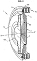
- the reference 1 designates the integrated burner door 2, subject of the invention.
- this is merely an example of a condensing heat exchanger of the type produced by GIANNONI FRANCE under the name "ISOTHERMIC” (registered trademark).
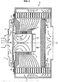
- This type of exchanger comprises two bundles of helical tubes coaxially mounted inside a gas-tight envelope, separated by a partition of thermally insulating material.
- the tubes are traversed by the fluid to be heated, water for example. They have an oval flattened section and the interstice between turns is calibrated and of small width.
- the burner is located inside one of the beams, said primary, and the hot gases from the burner through these interstices from the inside to the outside, with a high heat exchange coefficient. They then bypass the insulating partition and cross the interstices of the other beam, said secondary, in the opposite direction (from the outside towards the inside), before being evacuated out of the envelope by a conduit or a suitable cuff. .
- the door 1 is fixed in the frame 61 of the front wall of a heater AC whose shell 6 has a side wall 60 and a bottom wall 62 having an exhaust sleeve 620 intended to be connected to a conduit (not shown) for exhausting burnt gases.
- This shell 6 contains a tubular helical winding of stainless steel 7, of flattened and oval section, of axis X-X '. It is composed of a primary beam 70 and a secondary beam 71, separated by an insulating disc 600. It is a condensing heat exchanger, of the same type as those described in the aforementioned documents, suitable for heat water or any other fluid, which is circulated in the winding 7.
- the door 1 has a generally circular shape, centered on the axis XX 'and has peripheral fasteners (not shown) for mounting removably on the front of the device, for example using four ears arranged at 90 °, and screwed to the facade.
- the door 1 comprises a pair of thin walls, one outer 10, the other inner 11. These walls are made of stainless steel sheet cut and stamped.
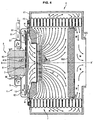
- this peripheral flange 100 has an annular cavity, facing inwards, which receives a seal 101 adapted to be applied, when the door is closed, against a support collar 72 fixed in the frame 61 and contact, by its internal face, against the first turn of the winding 7.
- the stamping of the outer plate 10 is such that it has an outwardly directed convexity, the central zone of which is pierced by a circular opening 102 centered on X-X '.
- the wall flanking this opening has a profile adapted for mounting and sealing - for example by means of screws or welding - a sleeve 5 (shown in dashed lines) for feeding the combustible gas mixture into the apparatus via a suitable conduit 50.
- the stamping of the inner plate 11 is such that it has an inwardly directed convexity, the central zone of which is pierced by a circular opening 103 centered on X-X '.
- This opening is bordered by an annular mouth on which is fixed the burner 2.
- the latter has the shape of a cylindrical cup of low height, the annular portion 20 is fitted and retained by clamping (press fit) and / or by some welding spots, on said mouth, while its flat bottom 21 is perforated, constituting the combustion surface.
- the burner has a composite structure, comprising a perforated stamped inner sheet and a fibrous and porous outer wall allowing a good attachment of the flame.
- the bottom 21 acting as a combustion surface could be slightly curved, with its convexity turned towards the inside of the apparatus, and its center of curvature centered on X-X '.
- This curved shape allows the dilation phenomena to be well absorbed, the combustion surface being able to deform naturally to take a more or less pronounced curvature depending on this expansion.
- a discoid plate 3 of small thickness In this space is housed a discoid plate 3 of small thickness, centered on X-X '. Its diameter is substantially larger than that of the openings 102 and 103; it is nevertheless slightly less than that of said free space.
- the plate 3 consists of two thin walls 30, 31, for example made of stainless steel sheet, fixed to one another at their periphery 300 in a sealed manner, for example by crimping and / or welding.
- the outer sheet 30 is flat;
- the inner plate 31 has an annular main zone which is also flat, parallel to the plate 30, and a central zone 310 which is slightly curved, with an inwardly turned convexity (burner side).
- an insulating material 32 for example a neutral gas such as nitrogen or a ceramic-based solid material. Its function is to limit heat transfer between the two walls.
- the inner wall 31 is provided at its periphery with several bosses, such as stampings 311, regularly distributed (for example six bosses at 60 ° angle) through which it is fixed to the sheet 11.
- This fixing is carried out for example by soldering points, in zones of restricted area, quasi-point, in order to limit the transfer of heat between the two walls 11 and 31, and also not to thwart the passage of gas between these last.
- bosses also act as spacers.
- the door 1 comprises, on the inside, an annular lining 4 made of thermally insulating material, and resistant to heat, for example ceramic or ceramic material.
- This lining is axially fitted by its central opening on the cylindrical portion 20 of the burner 2 and is retained against the inner face of the wall 11 by an appropriately shaped internal rim 720 of the bearing flange 72.
- the annular liner 4 covers the wall 11 at the periphery of the burner, up to the level of the winding 7, constituting a heat shield with respect to very hot gases from the burner present inside the primary beam of the exchanger.
- the burner having been ignited, by means of a suitable ignition system (not shown), and the gaseous air / fuel fuel mixture being fed into the sleeve 5 via the conduit 50, the apparatus operates as explained above. after.
- the flow of gas which enters the apparatus passes through the opening 102 (arrows F), meets the flat wall 30 of the plate 3 which faces it, and is split into a multitude of gaseous currents which are deflected at right angles and which flow radially from the axis XX 'towards the outside of the disk, to the peripheral edge 300 (arrows G), while licking the wall 30; arrived beyond the edge 300, they bypass it (arrows H) and flow in the opposite direction, in the direction of the axis X-X ', towards the outlet opening 103, this time licking the wall 31 (arrows I) to finally penetrate inside the burner 2.
- the fluid circulating inside the winding is first preheated in the secondary beam 71, then heated in the primary beam 70, as is well known.
- the inner plate 31 of the deflector plate 3 is at a temperature substantially higher than its outer plate 30.
- this temperature varies relatively significantly, and frequently, during the phases of implementation. route and stop the device.
- the temperature of the outer wall 10 of the door is of the order of 25 to 30 ° C significantly lower than the temperature at which the outer wall of a traditional door would be raised, which temperature would correspond to the external temperature of the wall 11 if it was not cooled by the incoming gas mixture, namely between 120 and 180 ° C approximately.
- the figure 3 refers to an embodiment of the door 1 which differs from the previous only by the type of burner integrated to the door.
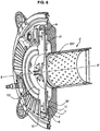
- the figures 4 and 5 relate to an embodiment of the gate 1 which differs from that of figures 1 and 2 in that an electric fan motor 8 centrifugal type, centered on the axis XX, is integrated in the door.
- annular stator 80 which is fixed to the outer plate 10 by means of suitable fastening tabs, not shown.
- the blade holder disc 83 extends in a general plane perpendicular to the X-X 'axis, close to the outer face of the deflector plate 3.
- the blades 82 are fixed on the outer face of the disc 83.
- the stator 80 of the fan motor is positioned with a certain clearance (annular space) inside the inlet opening 102 of the outer plate 10.
- This opening has the shape of a mouth surrounded by an annular collector 9 (approximately O-ring) centered on the X-X 'axis.
- This collector can be attached or form an integral part of the sheet 10.
- the collector 9 is connected to a conduit 91 for supplying a gaseous oxidizer, such as butane or propane, for example. Its inner annular wall and / or that of the mouth which it surrounds is pierced with a plurality of orifices 90 regularly distributed at its periphery, making it possible to diffuse the gaseous oxidant in the form of jets into the annular gap surrounding the stator .
- a gaseous oxidizer such as butane or propane
- the gaseous oxidant passes through the conduit 91 (arrow C), arrives in the annular collector 9 (arrows D), leaves through the orifices 90 and is sucked inside the device by the blades 82 in motion (arrows F).
- the latter also aspire ambient air (fuel) which is taken outside (arrows E) and passes into the same annular gap, mixing with the gas from the orifices 90.
- the gas streams leaving the inlet mouth 102 do not actually lick the outer face of the plate 3.
- the plate 3 acts as a heat shield; since it is not in contact with the rotating disc 83, there is no heat transfer between these two elements, which puts the motor-fan away from temperature rises.
- the figures 6 and 7 relate to an alternative embodiment of the door 1, which differs from the previous by the shape of the outer plate of the deflector plate. The latter is then referenced 3 '.
- This outer sheet, referenced 30 ' has a flat annular main zone, parallel to the inner plate 31 and a projecting pin-shaped central zone 301', the tip of which is turned towards the inlet opening 102 of the door 1.
- This form is obtained for example by stamping.
- the stud 301 improves the radial distribution of the incoming airflow, as represented by the arrows P.
- the fan which brings the air fuel / gas fuel mixture into the sleeve 5 is less stressed and can turn less quickly to obtain the same flow.
- the deflector plate 3 'does not necessarily have a strictly circular outline, but that it may have at its periphery indentations 33 of various shapes, adapted to the passage of various elements, such as ignition electrodes or ionization for example.
Landscapes
- Engineering & Computer Science (AREA)
- Chemical & Material Sciences (AREA)
- Combustion & Propulsion (AREA)
- Mechanical Engineering (AREA)
- General Engineering & Computer Science (AREA)
- Physics & Mathematics (AREA)
- Thermal Sciences (AREA)
- Gas Burners (AREA)
- Housings, Intake/Discharge, And Installation Of Fluid Heaters (AREA)
- Air Supply (AREA)
- Instantaneous Water Boilers, Portable Hot-Water Supply Apparatuses, And Control Of Portable Hot-Water Supply Apparatuses (AREA)
- Baking, Grill, Roasting (AREA)
Claims (15)
- Tür mit integriertem Brenner für Heizgerät, die auf ihrer Innenseite mit einem Gasbrenner (2; 2') und auf ihrer Außenseite mit einem Zufuhrsystem (5; 8-9) eines brennbaren Gasgemischs zum Brenner ausgestattet ist, wobei diese Tür (1) ausgebildet ist, um in den Rahmen (61) einer Wand des Geräts eingesetzt zu sein und um an diesem Rahmen lösbar befestigt zu sein, und ein Paar Metallbleche (10, 11) aufweist, die an ihrem Umfang (100) fest miteinander verbunden sind, wobei das äußere Blech (10) in seinem zentralen Bereich eine Eingangsöffnung (102) für die Ankunft des Gasgemischs aufweist, wogegen das innere Blech (11) in seinem zentralen Bereich eine zur Eingangsöffnung (102) koaxiale Ausgangsöffnung (103) aufweist, an welcher der Brenner (2; 2') befestigt ist, wobei diese beiden Bleche (10, 11) voneinander beabstandet sind und dabei zwischen sich einen Raum bilden, in dessen Innern eine Deflektorplatte (3, 3') fest montiert ist, wobei diese Deflektorplatte (3, 3') die Form einer Scheibe hat, deren Durchmesser etwas größer ist als der der Eingangs- (102) und Ausgangsöffnung (103) der Tür, und die auf der Achse (X-X') dieser Öffnungen zentriert und senkrecht zu dieser montiert ist, wobei die Tür dadurch gekennzeichnet ist, dass diese Deflektorplatte (3, 3') aus zwei parallelen, etwas beabstandeten Blechen (30, 30', 31) zusammengesetzt ist, die aneinander an ihrem Umfang (300) befestigt sind, wobei diese Deflektorplatte (3, 3') damit derart ausgebildet und dimensioniert ist, dass der Gasgemischstrom, der durch die Eingangsöffnung (102) in das Gerät strömt, nach außerhalb der Deflektorplatte (3, 3') abgelenkt wird, deren Umfangsrand (300) von außen nach innen umströmt und danach an ihrer Innenseite entlang strömt, um durch die Ausgangsöffnung (103) auszutreten und in den Brenner (2; 2') einzudringen.
- Tür mit integriertem Brenner nach Anspruch 1, dadurch gekennzeichnet, dass die Eingangs- (102) und Ausgangsöffnung (103) kreisrund sind.
- Tür mit integriertem Brenner nach Anspruch 1 oder Anspruch 2, dadurch gekennzeichnet, dass die Deflektorplatte (3, 3') auf dem Umfangsrandabschnitt ihrer Innenseite Klötze oder Wülste (311) besitzt, anhand derer diese Seite auf der Außenseite des inneren Blechs (11) angelegt und fixiert wird, und zwar mit quasi punktuellen Kontaktzonen, die den Durchgang des Gasgemischs nicht behindern, dabei aber die Übertragung von Wärme vom inneren Blech (11) auf die Deflektorplatte (3) begrenzen.
- Tür mit integriertem Brenner nach einem der vorangehenden Ansprüche, dadurch gekennzeichnet, dass die Deflektorplatte (3, 3') mit einer thermischen Isolation (32) ausgestattet ist, die sich zwischen den Blechen (30, 31) befindet, wobei diese Isolation aus einem neutralen Gas wie beispielsweise Stickstoff oder aus einem Feststoff, beispielsweise auf der Basis von Keramik, besteht.
- Tür mit integriertem Brenner nach einem der vorangehenden Ansprüche, dadurch gekennzeichnet, dass das innere Blech (31), welches die Deflektorplatte (3, 3') bildet, einen gewölbten zentralen Abschnitt (310) besitzt, welcher ihre elastische Verformung erlaubt und der es ihr gestattet, die in Verbindung mit den Temperaturschwankungen, je nachdem, ob das Gerät im Betrieb oder ausgeschaltet ist, erzeugten Ausdehnungen und Kontraktionen zu absorbieren.
- Tür mit integriertem Brenner nach einem der vorangehenden Ansprüche, dadurch gekennzeichnet, dass das äußere Blech (30'), welches die Deflektorplatte (3') bildet, einen zapfenförmigen zentralen Abschnitt (301') besitzt, dessen Spitze in Richtung der Eingangsöffnung (102) zeigt, wobei dieser Zapfen die radiale Verteilung des durch die Eingangsöffnung eindringenden Gasgemischflusses fördert.
- Tür mit integriertem Brenner nach einem der vorangehenden Ansprüche, dadurch gekennzeichnet, dass der Brenner (2) flach ist, wobei seine Verbrennungsoberfläche senkrecht zur Achse (X-X') der Öffnungen ist.
- Tür mit integriertem Brenner nach einem der Ansprüche 1 bis 6, dadurch gekennzeichnet, dass der Brenner leicht gewölbt ist und seine Verbrennungsoberfläche konvex, auf der Achse (X-X') der Öffnungen zentriert ist.
- Tür mit integriertem Brenner nach einem der Ansprüche 1 bis 6, dadurch gekennzeichnet, dass der Brenner (2') ringförmig ist, wobei seine zylindrische Verbrennungsoberfläche auf der Achse (X-X') der Öffnungen zentriert ist.
- Tür mit integriertem Brenner nach einem der vorangehenden Ansprüche, dadurch gekennzeichnet, dass die Zone des inneren Blechs (11), welche die Ausgangsöffnung umgibt, auf ihrer Innenseite mit einem hitzebeständigen und thermisch isolierenden Material (4) wie ein Keramikmaterial oder ein Material auf der Basis von Keramik verkleidet ist.
- Tür mit integriertem Brenner nach einem der vorangehenden Ansprüche, dadurch gekennzeichnet, dass sie auf ihrer Innenseite mit einer Umfangsdichtung (101) ausgestattet ist, die imstande ist, sich an die Außenseite eines Kragens (72) anzuschmiegen, der mit dem Rahmen der Wand (61) fest verbunden ist.
- Tür mit integriertem Brenner nach einem der vorangehenden Ansprüche, dadurch gekennzeichnet, dass das Zufuhrsystem des brennbaren Gasgemischs eine im Bereich der Eingangsöffnung (102) des äußeren Blechs (10) montierte und an diesem befestige Manschette (5) umfasst.
- Tür mit integriertem Brenner nach einem der Ansprüche 1 bis 11, dadurch gekennzeichnet, dass sie mit einem elektrischen Motorlüfter (8) ausgestattet ist, der mit dem äußeren Blech (10) fest verbunden und ausgebildet ist, um das Gasgemisch durch die Eingangsöffnung (102) anzusaugen und es zum Brenner (2; 2') zu befördern.
- Tür mit integriertem Brenner nach Anspruch 13, dadurch gekennzeichnet, dass der Motorlüfter (8) vom Typ Zentrifuge ist und eine Reihe rotierender Schaufeln (82) besitzt, die in einer Vertiefung der Wand des äußeren Blechs (10) untergebracht sind, die als Gehäuse dient, und die sich in der Nähe der Außenseite der Deflektorplatte (3) erstrecken.
- Tür mit integriertem Brenner nach Anspruch 14, dadurch gekennzeichnet, dass zum einen der Stator (80) des Motorlüfters (8) in der Eingangsöffnung (102) des äußeren Blechs (10) positioniert ist und dass zum anderen das Zufuhrsystem des brennbaren Gasgemischs einen ringförmigen Sammler (9) umfasst, der im Bereich dieser Eingangsöffnung (102) montiert und am äußeren Blech (10) befestigt ist und somit den Stator (80) des Motorlüfters umgibt, wobei dieser Sammler (9) durch eine Leitung (91) mit gasförmigem Brennstoff versorgt wird und seine Wand von einer Vielzahl radialer Öffnungen (90) durchbrochen ist, durch welche der gasförmige Brennstoff in den ringförmigen Spalt verteilt wird, der den Stator (80) vom Rand der Eingangsöffnung (102) trennt, um danach von den rotierenden Schaufeln (82) angesaugt zu werden, wobei zur gleichen Zeit die (die Verbrennung fördernde) Umgebungsluft über denselben ringförmigen Spalt angesaugt wird.
Applications Claiming Priority (2)
| Application Number | Priority Date | Filing Date | Title |
|---|---|---|---|
| FR0951422A FR2942866B1 (fr) | 2009-03-06 | 2009-03-06 | Porte a bruleur integre pour appareil de chauffage |
| PCT/EP2010/051126 WO2010100004A1 (fr) | 2009-03-06 | 2010-01-29 | Porte à brûleur intégré pour appareil de chauffage |
Publications (2)
| Publication Number | Publication Date |
|---|---|
| EP2404112A1 EP2404112A1 (de) | 2012-01-11 |
| EP2404112B1 true EP2404112B1 (de) | 2016-06-29 |
Family
ID=41151784
Family Applications (1)
| Application Number | Title | Priority Date | Filing Date |
|---|---|---|---|
| EP10701549.7A Active EP2404112B1 (de) | 2009-03-06 | 2010-01-29 | Tür mit eingebautem brenner für heizgerät |
Country Status (9)
| Country | Link |
|---|---|
| US (2) | US8978638B2 (de) |
| EP (1) | EP2404112B1 (de) |
| JP (1) | JP5342023B2 (de) |
| KR (1) | KR101534894B1 (de) |
| CN (1) | CN102341651B (de) |
| CA (1) | CA2752093C (de) |
| FR (1) | FR2942866B1 (de) |
| RU (1) | RU2484376C1 (de) |
| WO (1) | WO2010100004A1 (de) |
Cited By (1)
| Publication number | Priority date | Publication date | Assignee | Title |
|---|---|---|---|---|
| DE102018102935A1 (de) | 2018-02-09 | 2019-08-14 | Vaillant Gmbh | Wärmezelle mit gekühlter Brennertür |
Families Citing this family (27)
| Publication number | Priority date | Publication date | Assignee | Title |
|---|---|---|---|---|
| FR2955929B1 (fr) | 2010-02-01 | 2014-04-18 | Mer Joseph Le | Echangeur de chaleur a condensation pour plusieurs fluides et dispositif de production de fluides chauds comprenant un tel echangeur |
| FR2972789B1 (fr) | 2011-03-14 | 2013-04-12 | Giannoni France | Appareil de chauffage au gaz a condensation |
| CN102563663A (zh) * | 2012-02-02 | 2012-07-11 | 安徽盛运机械股份有限公司 | 垃圾焚烧炉专用看火门 |
| PL3139106T3 (pl) | 2014-03-17 | 2019-07-31 | Condevo S.P.A. | Komórka wymiany ciepła i sposób |
| KR101594940B1 (ko) * | 2014-03-18 | 2016-02-17 | 주식회사 경동나비엔 | 열교환기 |
| KR101597980B1 (ko) * | 2014-03-18 | 2016-02-29 | 주식회사 경동나비엔 | 열교환기 및 열교환기를 구성하는 단위플레이트의 제조방법 |
| GB2525873A (en) * | 2014-05-07 | 2015-11-11 | Worgas Burners Ltd | Gas burner |
| EP3018408B1 (de) * | 2014-11-05 | 2017-06-07 | WORGAS BRUCIATORI S.r.l. | Brenner |
| US9631808B2 (en) * | 2014-11-21 | 2017-04-25 | Honeywell International Inc. | Fuel-air-flue gas burner |
| FR3047063B1 (fr) * | 2016-01-22 | 2018-11-30 | Sermeta | Dispositif d'echanges thermiques pour echangeur de chaleur a condensation |
| FR3047549B1 (fr) * | 2016-02-09 | 2019-05-10 | Sermeta | Deflecteur pour echangeur de chaleur a condensation et echangeur muni d'un tel deflecteur |
| NL2016755B1 (nl) * | 2016-05-10 | 2017-11-16 | Remeha B V | Warmtewisselaar. |
| US10627113B2 (en) * | 2016-12-29 | 2020-04-21 | Whirlpool Corporation | Distributed vertical flame burner |
| FR3062471B1 (fr) | 2017-01-27 | 2019-06-07 | Sermeta | Echangeur de chaleur |
| JP6834772B2 (ja) * | 2017-05-22 | 2021-02-24 | 株式会社ノーリツ | 温水装置 |
| US10753644B2 (en) | 2017-08-04 | 2020-08-25 | A. O. Smith Corporation | Water heater |
| IT201700096656A1 (it) * | 2017-08-28 | 2019-02-28 | Cosmogas Srl | Scambiatore di calore per una caldaia, e tubo di scambiatore di calore |
| DE102018102967A1 (de) * | 2018-02-09 | 2019-08-14 | Vaillant Gmbh | Wärmezelle mit metallischem Dämmring |
| US12338993B2 (en) | 2018-02-23 | 2025-06-24 | Fulton Group N.A., Inc. | Compact flat plate premix fuel combustion system, and fluid heating system and packaged burner system including the same |
| IT201800003438A1 (it) * | 2018-03-12 | 2019-09-12 | Athena S P A | Caldaia perfezionata |
| IT201800003451A1 (it) * | 2018-03-12 | 2019-09-12 | Condevo S P A | Porta di chiusura per cella di scambio di calore per caldaia |
| US11162710B2 (en) * | 2018-06-08 | 2021-11-02 | Intellihot, Inc. | Heat exchanger including flue flow path guide system |
| DE102018113993A1 (de) * | 2018-06-12 | 2019-12-12 | Vaillant Gmbh | Wärmezelle eines Heizgerätes |
| FR3125327B1 (fr) * | 2021-07-16 | 2023-09-29 | Sermeta | Echangeur de chaleur à condensation. |
| FR3125326B1 (fr) | 2021-07-16 | 2023-07-14 | Sermeta | Echangeur de chaleur |
| CN113819650A (zh) * | 2021-07-29 | 2021-12-21 | 浙江菲斯曼供热技术有限公司 | 加热装置 |
| WO2023028129A1 (en) * | 2021-08-25 | 2023-03-02 | Fulton Group N.A., Inc. | Compact flat plate premix fuel combustion system, and fluid heating system and packaged burner system including the same |
Family Cites Families (26)
| Publication number | Priority date | Publication date | Assignee | Title |
|---|---|---|---|---|
| DE206577C (de) * | ||||
| FR362304A (fr) * | 1906-01-10 | 1906-06-19 | Ferdinand Toth | Porte de foyer avec tiroir pour le réglage de l'admission d'air |
| FR429885A (fr) * | 1911-05-17 | 1911-10-03 | Leonhardt & Merkle | Porte de foyer avec installation pour le chauffage préalable de l'air secondaire |
| US1777065A (en) * | 1927-12-05 | 1930-09-30 | Milton M Yale | Air preheater |
| US1766191A (en) * | 1929-05-16 | 1930-06-24 | Nelson J Russell | Fuel-saving device |
| GB959310A (en) * | 1961-12-01 | 1964-05-27 | Vauxhall Boiler Company Ltd | Improvements in and relating to furnace doors |
| US3614388A (en) * | 1970-06-22 | 1971-10-19 | Aubrey C Robinson | Electric heating oven system |
| US4871014A (en) * | 1983-03-28 | 1989-10-03 | Tui Industries | Shell and tube heat exchanger |
| FR2553869B1 (fr) * | 1983-10-21 | 1988-01-08 | Lemer Joseph | Chaudiere a condensation pour chauffage a fluide caloporteur |
| AT388988B (de) * | 1987-01-23 | 1989-09-25 | Vaillant Gmbh | Kessel mit in einer oeffnung befestigtem geblaesebrenner |
| FR2700608B1 (fr) | 1993-01-15 | 1995-04-07 | Joseph Le Mer | Elément échangeur de chaleur, procédé et dispositif pour le fabriquer. |
| EP0657692B1 (de) * | 1993-12-06 | 2000-02-02 | Papst-Motoren Gmbh & Co. Kg | Brennergebläse für Gas-Vormischbrenner |
| JP3001398B2 (ja) * | 1995-04-11 | 2000-01-24 | 株式会社サムソン | 表面燃焼バーナの燃焼不良検出装置 |
| JP3540486B2 (ja) * | 1996-02-02 | 2004-07-07 | 三洋電機株式会社 | 液体燃料燃焼装置 |
| RU2090804C1 (ru) * | 1996-04-22 | 1997-09-20 | Рафаэл Газетов | Генератор тепла-утилизатор |
| FR2794521B1 (fr) * | 1999-06-04 | 2001-07-13 | Geminox | Bruleur a gaz a ventilation forcee pour chaudiere |
| CA2300839A1 (en) * | 2000-03-17 | 2001-09-17 | Asea Brown Boveri Inc. | Thermal equalizer |
| DE10051307B4 (de) * | 2000-10-17 | 2008-07-31 | Robert Bosch Gmbh | Vorrichtung zur Trennung von Gas und Flüssigkeit-Festkörperpartikeln aus einem in einer Leitung strömenden Gas-Flüssigkeit-Festkörperpartikelgemisch und Verfahren zur Trennung derselben |
| FR2835042B1 (fr) * | 2002-01-22 | 2004-12-17 | Mer Joseph Le | Bruleur a gaz, a face de combustion bipartite et chaudiere equipee d'un tel bruleur |
| US6908201B2 (en) | 2002-06-28 | 2005-06-21 | Silicon Light Machines Corporation | Micro-support structures |
| JP4087407B2 (ja) | 2002-10-16 | 2008-05-21 | ソシエテ、デチュード、エ、ド、レアリザシオン、メカニク、エンジニアリング、アン、テクノロジーズ、アバンセ | プラスチックケーシングを有する凝縮熱交換器 |
| FR2846075B1 (fr) * | 2002-10-16 | 2005-03-04 | Realisation Mecaniques Engenee | Echangeur de chaleur a condensation, a enveloppe plastique |
| FR2854229A1 (fr) * | 2003-04-25 | 2004-10-29 | Realisation Mecaniques Engenee | Echangeur de chaleur a condensation |
| DE102004005048A1 (de) * | 2004-01-30 | 2005-09-01 | Viessmann Werke Gmbh & Co Kg | Heizgerät |
| CA2579496A1 (en) * | 2004-04-23 | 2005-11-03 | Shell Internationale Research Maatschappij B.V. | Subsurface electrical heaters using nitride insulation |
| GB0522309D0 (en) * | 2005-11-01 | 2005-12-07 | Microgen Energy Ltd | An annular burner assembly |
-
2009
- 2009-03-06 FR FR0951422A patent/FR2942866B1/fr active Active
-
2010
- 2010-01-29 WO PCT/EP2010/051126 patent/WO2010100004A1/fr not_active Ceased
- 2010-01-29 KR KR1020117020721A patent/KR101534894B1/ko active Active
- 2010-01-29 CN CN201080009922.9A patent/CN102341651B/zh active Active
- 2010-01-29 CA CA2752093A patent/CA2752093C/fr active Active
- 2010-01-29 US US13/254,593 patent/US8978638B2/en active Active
- 2010-01-29 EP EP10701549.7A patent/EP2404112B1/de active Active
- 2010-01-29 JP JP2011552372A patent/JP5342023B2/ja active Active
- 2010-01-29 RU RU2011140497/06A patent/RU2484376C1/ru active
-
2015
- 2015-02-10 US US14/618,308 patent/US9816726B2/en active Active
Cited By (1)
| Publication number | Priority date | Publication date | Assignee | Title |
|---|---|---|---|---|
| DE102018102935A1 (de) | 2018-02-09 | 2019-08-14 | Vaillant Gmbh | Wärmezelle mit gekühlter Brennertür |
Also Published As
| Publication number | Publication date |
|---|---|
| US20150153067A1 (en) | 2015-06-04 |
| US9816726B2 (en) | 2017-11-14 |
| CN102341651B (zh) | 2014-05-07 |
| WO2010100004A1 (fr) | 2010-09-10 |
| FR2942866A1 (fr) | 2010-09-10 |
| JP5342023B2 (ja) | 2013-11-13 |
| RU2011140497A (ru) | 2013-04-20 |
| EP2404112A1 (de) | 2012-01-11 |
| US8978638B2 (en) | 2015-03-17 |
| FR2942866B1 (fr) | 2012-03-23 |
| CA2752093C (fr) | 2016-06-14 |
| KR101534894B1 (ko) | 2015-07-07 |
| US20120000456A1 (en) | 2012-01-05 |
| CA2752093A1 (fr) | 2010-09-10 |
| RU2484376C1 (ru) | 2013-06-10 |
| KR20110136802A (ko) | 2011-12-21 |
| CN102341651A (zh) | 2012-02-01 |
| JP2012519823A (ja) | 2012-08-30 |
Similar Documents
| Publication | Publication Date | Title |
|---|---|---|
| EP2404112B1 (de) | Tür mit eingebautem brenner für heizgerät | |
| EP0520913B1 (de) | Heizung mit katalytischem Brenner | |
| EP1561075B1 (de) | Kondensationswärmetauscher mit kunststoffmantel | |
| EP1618341B1 (de) | Brennwertwärmetauscher | |
| EP2540162B1 (de) | Gerät, Einheit und Verfahren zur manuellen und lokalisierten Unkrautbekämpfung | |
| FR2846075A1 (fr) | Echangeur de chaleur a condensation, a enveloppe plastique | |
| EP3026348B1 (de) | Gerät zum kochen mit gas, insbesondere gasherd | |
| FR2684747A3 (en) | Gas burner of the type with spray pipes | |
| EP1843101A2 (de) | Wärmetauschervorrichtung eines Gasbrenners | |
| CA1123285A (fr) | Procede de combustion d'un combustible liquide et bruleur pour sa mise en oeuvre | |
| FR2597578A1 (fr) | Appareil a bruleur, notamment chauffe-eau, muni d'une soufflante | |
| EP0679839A1 (de) | Verbesserungen an Gasbrennern | |
| FR2699993A1 (fr) | Appareil de séchage de matériaux en nappe tels que du papier par exemple. | |
| EP0651203B1 (de) | Gas-Strahlungsbrenner für Herd oder Kochmulde | |
| EP0486741A1 (de) | Gasheizgerät mit Infrarotstrahlung | |
| EP4048953B1 (de) | Kamin mit aufgehängtem herd | |
| EP4370840B1 (de) | Kondensationswärmetauscher | |
| FR2678356A1 (fr) | Bruleur catalytique a air induit. | |
| EP0660040A1 (de) | Brennerkopf für Brenner mit niedriger Schadstoffemission und Kessel versehen mit solchen Brenner | |
| EP1363072A1 (de) | Brennerkopf für Gaskochgerät | |
| FR2688298A1 (fr) | Appareil generateur d'air chaud a panneau catalytique dans une chambre de combustion. | |
| FR2606494A3 (fr) | Chaudiere de chauffage, notamment pour fonctionnement a basse temperature | |
| BE488716A (de) | ||
| BE479490A (de) | ||
| BE664471A (de) |
Legal Events
| Date | Code | Title | Description |
|---|---|---|---|
| PUAI | Public reference made under article 153(3) epc to a published international application that has entered the european phase |
Free format text: ORIGINAL CODE: 0009012 |
|
| 17P | Request for examination filed |
Effective date: 20110728 |
|
| AK | Designated contracting states |
Kind code of ref document: A1 Designated state(s): AT BE BG CH CY CZ DE DK EE ES FI FR GB GR HR HU IE IS IT LI LT LU LV MC MK MT NL NO PL PT RO SE SI SK SM TR |
|
| DAX | Request for extension of the european patent (deleted) | ||
| RAP1 | Party data changed (applicant data changed or rights of an application transferred) |
Owner name: SERMETA |
|
| 111Z | Information provided on other rights and legal means of execution |
Free format text: AT BE BG CH CY CZ DE DK EE ES FI FR GB GR HR HU IE IS IT LT LU LV MC MK MT NL NO PL PT RO SE SI SK SM TR Effective date: 20140909 |
|
| GRAP | Despatch of communication of intention to grant a patent |
Free format text: ORIGINAL CODE: EPIDOSNIGR1 |
|
| INTG | Intention to grant announced |
Effective date: 20160302 |
|
| GRAS | Grant fee paid |
Free format text: ORIGINAL CODE: EPIDOSNIGR3 |
|
| GRAA | (expected) grant |
Free format text: ORIGINAL CODE: 0009210 |
|
| AK | Designated contracting states |
Kind code of ref document: B1 Designated state(s): AT BE BG CH CY CZ DE DK EE ES FI FR GB GR HR HU IE IS IT LI LT LU LV MC MK MT NL NO PL PT RO SE SI SK SM TR |
|
| REG | Reference to a national code |
Ref country code: GB Ref legal event code: FG4D Free format text: NOT ENGLISH |
|
| REG | Reference to a national code |
Ref country code: CH Ref legal event code: EP |
|
| REG | Reference to a national code |
Ref country code: AT Ref legal event code: REF Ref document number: 809414 Country of ref document: AT Kind code of ref document: T Effective date: 20160715 |
|
| REG | Reference to a national code |
Ref country code: IE Ref legal event code: FG4D Free format text: LANGUAGE OF EP DOCUMENT: FRENCH |
|
| REG | Reference to a national code |
Ref country code: DE Ref legal event code: R096 Ref document number: 602010034282 Country of ref document: DE |
|
| REG | Reference to a national code |
Ref country code: NL Ref legal event code: FP |
|
| REG | Reference to a national code |
Ref country code: LT Ref legal event code: MG4D |
|
| PG25 | Lapsed in a contracting state [announced via postgrant information from national office to epo] |
Ref country code: FI Free format text: LAPSE BECAUSE OF FAILURE TO SUBMIT A TRANSLATION OF THE DESCRIPTION OR TO PAY THE FEE WITHIN THE PRESCRIBED TIME-LIMIT Effective date: 20160629 Ref country code: NO Free format text: LAPSE BECAUSE OF FAILURE TO SUBMIT A TRANSLATION OF THE DESCRIPTION OR TO PAY THE FEE WITHIN THE PRESCRIBED TIME-LIMIT Effective date: 20160929 Ref country code: LT Free format text: LAPSE BECAUSE OF FAILURE TO SUBMIT A TRANSLATION OF THE DESCRIPTION OR TO PAY THE FEE WITHIN THE PRESCRIBED TIME-LIMIT Effective date: 20160629 |
|
| PG25 | Lapsed in a contracting state [announced via postgrant information from national office to epo] |
Ref country code: HR Free format text: LAPSE BECAUSE OF FAILURE TO SUBMIT A TRANSLATION OF THE DESCRIPTION OR TO PAY THE FEE WITHIN THE PRESCRIBED TIME-LIMIT Effective date: 20160629 Ref country code: GR Free format text: LAPSE BECAUSE OF FAILURE TO SUBMIT A TRANSLATION OF THE DESCRIPTION OR TO PAY THE FEE WITHIN THE PRESCRIBED TIME-LIMIT Effective date: 20160930 Ref country code: SE Free format text: LAPSE BECAUSE OF FAILURE TO SUBMIT A TRANSLATION OF THE DESCRIPTION OR TO PAY THE FEE WITHIN THE PRESCRIBED TIME-LIMIT Effective date: 20160629 Ref country code: LV Free format text: LAPSE BECAUSE OF FAILURE TO SUBMIT A TRANSLATION OF THE DESCRIPTION OR TO PAY THE FEE WITHIN THE PRESCRIBED TIME-LIMIT Effective date: 20160629 |
|
| REG | Reference to a national code |
Ref country code: AT Ref legal event code: MK05 Ref document number: 809414 Country of ref document: AT Kind code of ref document: T Effective date: 20160629 |
|
| REG | Reference to a national code |
Ref country code: FR Ref legal event code: PLFP Year of fee payment: 8 |
|
| PG25 | Lapsed in a contracting state [announced via postgrant information from national office to epo] |
Ref country code: EE Free format text: LAPSE BECAUSE OF FAILURE TO SUBMIT A TRANSLATION OF THE DESCRIPTION OR TO PAY THE FEE WITHIN THE PRESCRIBED TIME-LIMIT Effective date: 20160629 Ref country code: CZ Free format text: LAPSE BECAUSE OF FAILURE TO SUBMIT A TRANSLATION OF THE DESCRIPTION OR TO PAY THE FEE WITHIN THE PRESCRIBED TIME-LIMIT Effective date: 20160629 Ref country code: SK Free format text: LAPSE BECAUSE OF FAILURE TO SUBMIT A TRANSLATION OF THE DESCRIPTION OR TO PAY THE FEE WITHIN THE PRESCRIBED TIME-LIMIT Effective date: 20160629 Ref country code: IS Free format text: LAPSE BECAUSE OF FAILURE TO SUBMIT A TRANSLATION OF THE DESCRIPTION OR TO PAY THE FEE WITHIN THE PRESCRIBED TIME-LIMIT Effective date: 20161029 Ref country code: RO Free format text: LAPSE BECAUSE OF FAILURE TO SUBMIT A TRANSLATION OF THE DESCRIPTION OR TO PAY THE FEE WITHIN THE PRESCRIBED TIME-LIMIT Effective date: 20160629 |
|
| PG25 | Lapsed in a contracting state [announced via postgrant information from national office to epo] |
Ref country code: SM Free format text: LAPSE BECAUSE OF FAILURE TO SUBMIT A TRANSLATION OF THE DESCRIPTION OR TO PAY THE FEE WITHIN THE PRESCRIBED TIME-LIMIT Effective date: 20160629 Ref country code: PL Free format text: LAPSE BECAUSE OF FAILURE TO SUBMIT A TRANSLATION OF THE DESCRIPTION OR TO PAY THE FEE WITHIN THE PRESCRIBED TIME-LIMIT Effective date: 20160629 Ref country code: AT Free format text: LAPSE BECAUSE OF FAILURE TO SUBMIT A TRANSLATION OF THE DESCRIPTION OR TO PAY THE FEE WITHIN THE PRESCRIBED TIME-LIMIT Effective date: 20160629 Ref country code: ES Free format text: LAPSE BECAUSE OF FAILURE TO SUBMIT A TRANSLATION OF THE DESCRIPTION OR TO PAY THE FEE WITHIN THE PRESCRIBED TIME-LIMIT Effective date: 20160629 Ref country code: PT Free format text: LAPSE BECAUSE OF FAILURE TO SUBMIT A TRANSLATION OF THE DESCRIPTION OR TO PAY THE FEE WITHIN THE PRESCRIBED TIME-LIMIT Effective date: 20161031 |
|
| REG | Reference to a national code |
Ref country code: DE Ref legal event code: R097 Ref document number: 602010034282 Country of ref document: DE |
|
| PLBE | No opposition filed within time limit |
Free format text: ORIGINAL CODE: 0009261 |
|
| STAA | Information on the status of an ep patent application or granted ep patent |
Free format text: STATUS: NO OPPOSITION FILED WITHIN TIME LIMIT |
|
| PG25 | Lapsed in a contracting state [announced via postgrant information from national office to epo] |
Ref country code: DK Free format text: LAPSE BECAUSE OF FAILURE TO SUBMIT A TRANSLATION OF THE DESCRIPTION OR TO PAY THE FEE WITHIN THE PRESCRIBED TIME-LIMIT Effective date: 20160629 Ref country code: BE Free format text: LAPSE BECAUSE OF NON-PAYMENT OF DUE FEES Effective date: 20170131 |
|
| 26N | No opposition filed |
Effective date: 20170330 |
|
| PG25 | Lapsed in a contracting state [announced via postgrant information from national office to epo] |
Ref country code: BG Free format text: LAPSE BECAUSE OF FAILURE TO SUBMIT A TRANSLATION OF THE DESCRIPTION OR TO PAY THE FEE WITHIN THE PRESCRIBED TIME-LIMIT Effective date: 20160929 Ref country code: SI Free format text: LAPSE BECAUSE OF FAILURE TO SUBMIT A TRANSLATION OF THE DESCRIPTION OR TO PAY THE FEE WITHIN THE PRESCRIBED TIME-LIMIT Effective date: 20160629 |
|
| REG | Reference to a national code |
Ref country code: CH Ref legal event code: PL |
|
| PG25 | Lapsed in a contracting state [announced via postgrant information from national office to epo] |
Ref country code: MC Free format text: LAPSE BECAUSE OF FAILURE TO SUBMIT A TRANSLATION OF THE DESCRIPTION OR TO PAY THE FEE WITHIN THE PRESCRIBED TIME-LIMIT Effective date: 20160629 |
|
| PG25 | Lapsed in a contracting state [announced via postgrant information from national office to epo] |
Ref country code: CH Free format text: LAPSE BECAUSE OF NON-PAYMENT OF DUE FEES Effective date: 20170131 Ref country code: LI Free format text: LAPSE BECAUSE OF NON-PAYMENT OF DUE FEES Effective date: 20170131 |
|
| REG | Reference to a national code |
Ref country code: IE Ref legal event code: MM4A |
|
| PG25 | Lapsed in a contracting state [announced via postgrant information from national office to epo] |
Ref country code: LU Free format text: LAPSE BECAUSE OF NON-PAYMENT OF DUE FEES Effective date: 20170129 |
|
| REG | Reference to a national code |
Ref country code: FR Ref legal event code: PLFP Year of fee payment: 9 |
|
| REG | Reference to a national code |
Ref country code: FR Ref legal event code: RG Effective date: 20180108 |
|
| REG | Reference to a national code |
Ref country code: BE Ref legal event code: MM Effective date: 20170131 |
|
| PG25 | Lapsed in a contracting state [announced via postgrant information from national office to epo] |
Ref country code: IE Free format text: LAPSE BECAUSE OF NON-PAYMENT OF DUE FEES Effective date: 20170129 |
|
| PG25 | Lapsed in a contracting state [announced via postgrant information from national office to epo] |
Ref country code: MT Free format text: LAPSE BECAUSE OF FAILURE TO SUBMIT A TRANSLATION OF THE DESCRIPTION OR TO PAY THE FEE WITHIN THE PRESCRIBED TIME-LIMIT Effective date: 20160629 |
|
| PG25 | Lapsed in a contracting state [announced via postgrant information from national office to epo] |
Ref country code: HU Free format text: LAPSE BECAUSE OF FAILURE TO SUBMIT A TRANSLATION OF THE DESCRIPTION OR TO PAY THE FEE WITHIN THE PRESCRIBED TIME-LIMIT; INVALID AB INITIO Effective date: 20100129 |
|
| PG25 | Lapsed in a contracting state [announced via postgrant information from national office to epo] |
Ref country code: CY Free format text: LAPSE BECAUSE OF NON-PAYMENT OF DUE FEES Effective date: 20160629 |
|
| PG25 | Lapsed in a contracting state [announced via postgrant information from national office to epo] |
Ref country code: MK Free format text: LAPSE BECAUSE OF FAILURE TO SUBMIT A TRANSLATION OF THE DESCRIPTION OR TO PAY THE FEE WITHIN THE PRESCRIBED TIME-LIMIT Effective date: 20160629 |
|
| P01 | Opt-out of the competence of the unified patent court (upc) registered |
Effective date: 20230428 |
|
| PGFP | Annual fee paid to national office [announced via postgrant information from national office to epo] |
Ref country code: DE Payment date: 20250116 Year of fee payment: 16 |
|
| PGFP | Annual fee paid to national office [announced via postgrant information from national office to epo] |
Ref country code: IT Payment date: 20250109 Year of fee payment: 16 Ref country code: GB Payment date: 20250123 Year of fee payment: 16 |
|
| PGFP | Annual fee paid to national office [announced via postgrant information from national office to epo] |
Ref country code: TR Payment date: 20250124 Year of fee payment: 16 |
|
| PGFP | Annual fee paid to national office [announced via postgrant information from national office to epo] |
Ref country code: NL Payment date: 20251230 Year of fee payment: 17 Ref country code: FR Payment date: 20251212 Year of fee payment: 17 |