EP2403694B1 - Schneidvorrichtung - Google Patents
Schneidvorrichtung Download PDFInfo
- Publication number
- EP2403694B1 EP2403694B1 EP20100704511 EP10704511A EP2403694B1 EP 2403694 B1 EP2403694 B1 EP 2403694B1 EP 20100704511 EP20100704511 EP 20100704511 EP 10704511 A EP10704511 A EP 10704511A EP 2403694 B1 EP2403694 B1 EP 2403694B1
- Authority
- EP
- European Patent Office
- Prior art keywords
- circular blade
- drive
- accordance
- cover
- cover element
- Prior art date
- Legal status (The legal status is an assumption and is not a legal conclusion. Google has not performed a legal analysis and makes no representation as to the accuracy of the status listed.)
- Not-in-force
Links
Images
Classifications
-
- B—PERFORMING OPERATIONS; TRANSPORTING
- B26—HAND CUTTING TOOLS; CUTTING; SEVERING
- B26D—CUTTING; DETAILS COMMON TO MACHINES FOR PERFORATING, PUNCHING, CUTTING-OUT, STAMPING-OUT OR SEVERING
- B26D7/00—Details of apparatus for cutting, cutting-out, stamping-out, punching, perforating, or severing by means other than cutting
-
- B—PERFORMING OPERATIONS; TRANSPORTING
- B26—HAND CUTTING TOOLS; CUTTING; SEVERING
- B26D—CUTTING; DETAILS COMMON TO MACHINES FOR PERFORATING, PUNCHING, CUTTING-OUT, STAMPING-OUT OR SEVERING
- B26D1/00—Cutting through work characterised by the nature or movement of the cutting member or particular materials not otherwise provided for; Apparatus or machines therefor; Cutting members therefor
- B26D1/01—Cutting through work characterised by the nature or movement of the cutting member or particular materials not otherwise provided for; Apparatus or machines therefor; Cutting members therefor involving a cutting member which does not travel with the work
- B26D1/12—Cutting through work characterised by the nature or movement of the cutting member or particular materials not otherwise provided for; Apparatus or machines therefor; Cutting members therefor involving a cutting member which does not travel with the work having a cutting member moving about an axis
- B26D1/14—Cutting through work characterised by the nature or movement of the cutting member or particular materials not otherwise provided for; Apparatus or machines therefor; Cutting members therefor involving a cutting member which does not travel with the work having a cutting member moving about an axis with a circular cutting member, e.g. disc cutter
- B26D1/157—Cutting through work characterised by the nature or movement of the cutting member or particular materials not otherwise provided for; Apparatus or machines therefor; Cutting members therefor involving a cutting member which does not travel with the work having a cutting member moving about an axis with a circular cutting member, e.g. disc cutter rotating about a movable axis
- B26D1/16—Cutting through work characterised by the nature or movement of the cutting member or particular materials not otherwise provided for; Apparatus or machines therefor; Cutting members therefor involving a cutting member which does not travel with the work having a cutting member moving about an axis with a circular cutting member, e.g. disc cutter rotating about a movable axis mounted on a movable arm or the like
-
- B—PERFORMING OPERATIONS; TRANSPORTING
- B26—HAND CUTTING TOOLS; CUTTING; SEVERING
- B26D—CUTTING; DETAILS COMMON TO MACHINES FOR PERFORATING, PUNCHING, CUTTING-OUT, STAMPING-OUT OR SEVERING
- B26D2210/00—Machines or methods used for cutting special materials
- B26D2210/02—Machines or methods used for cutting special materials for cutting food products, e.g. food slicers
-
- Y—GENERAL TAGGING OF NEW TECHNOLOGICAL DEVELOPMENTS; GENERAL TAGGING OF CROSS-SECTIONAL TECHNOLOGIES SPANNING OVER SEVERAL SECTIONS OF THE IPC; TECHNICAL SUBJECTS COVERED BY FORMER USPC CROSS-REFERENCE ART COLLECTIONS [XRACs] AND DIGESTS
- Y10—TECHNICAL SUBJECTS COVERED BY FORMER USPC
- Y10T—TECHNICAL SUBJECTS COVERED BY FORMER US CLASSIFICATION
- Y10T83/00—Cutting
- Y10T83/485—Cutter with timed stroke relative to moving work
- Y10T83/494—Uniform periodic tool actuation
- Y10T83/496—With periodic lateral feed of tool or work
-
- Y—GENERAL TAGGING OF NEW TECHNOLOGICAL DEVELOPMENTS; GENERAL TAGGING OF CROSS-SECTIONAL TECHNOLOGIES SPANNING OVER SEVERAL SECTIONS OF THE IPC; TECHNICAL SUBJECTS COVERED BY FORMER USPC CROSS-REFERENCE ART COLLECTIONS [XRACs] AND DIGESTS
- Y10—TECHNICAL SUBJECTS COVERED BY FORMER USPC
- Y10T—TECHNICAL SUBJECTS COVERED BY FORMER US CLASSIFICATION
- Y10T83/00—Cutting
- Y10T83/768—Rotatable disc tool pair or tool and carrier
- Y10T83/7793—Means to rotate or oscillate tool
- Y10T83/7797—Including means to rotate both elements of tool pair
- Y10T83/7801—Including means to rotate both elements at different speeds
-
- Y—GENERAL TAGGING OF NEW TECHNOLOGICAL DEVELOPMENTS; GENERAL TAGGING OF CROSS-SECTIONAL TECHNOLOGIES SPANNING OVER SEVERAL SECTIONS OF THE IPC; TECHNICAL SUBJECTS COVERED BY FORMER USPC CROSS-REFERENCE ART COLLECTIONS [XRACs] AND DIGESTS
- Y10—TECHNICAL SUBJECTS COVERED BY FORMER USPC
- Y10T—TECHNICAL SUBJECTS COVERED BY FORMER US CLASSIFICATION
- Y10T83/00—Cutting
- Y10T83/869—Means to drive or to guide tool
- Y10T83/872—With guard means
- Y10T83/8722—Static
Definitions
- the present invention relates to a cutting device for slicing food products, in particular a high-performance slicer, comprising a drivable circular blade which rotates about a knife axis which circulates on a path about a central axis and a side of the circular blade facing away from a product to be sliced , relative to the circular blade rotatable cover.
- the cover member is used in such cutting devices to prevent interference of separated product slices on the circular blade.
- the cover may be formed as a flat, coaxial with the circular blade disc. Separated slices of product come into contact with the disc and are stripped therefrom. In this way, even relatively soft food products can be cut with high cutting rate.
- a cutting device with a cover is for example from the EP 0 169 399 B1 known.
- the disclosed there cover plate is connected to a drive and can be rotated at an adjustable speed to provide a relative rotation between the circular blade and cover. Such a relative rotation can be used to selectively influence the Thomasgutposition réelle.
- GB 369 091 A refers to a bread slicer, which is designed to leave a narrow connecting web between the slices when cutting through an elongate bread slat so as to be able to package the sliced bread slug as a whole.
- the machine has a planetary circular blade.
- a shield covers the circular blade partially and is attached to a hood which rotates together with the knife rocker about the central axis.
- the cover element is driven by an auxiliary drive such that it rotates relative to the circular blade about the blade axis, wherein the auxiliary drive is derived from a drive of the circular blade. It is therefore not an independent and separately to be driven drive for the cover provided, but it is used the already existing drive the circular blade to move the cover in the desired manner. According to the invention, it has been recognized that not only can costs be saved by means of an auxiliary drive derived from a drive of the circular blade, but also an improvement in the reliability and a reduction in the susceptibility to errors can generally be achieved.
- auxiliary drive is designed to prevent self-rotation of the cover element about the blade axis relative to the product to be sliced during the circulation movement. It is thus avoided that a separated product disc is taken away by the cover and uncontrollably thrown away.
- the auxiliary drive is derived from a drive of the circular blade, which ensures the orbital movement about the central axis.
- the cover element during the entire circulation movement can be prevented in a relatively simple manner.
- the auxiliary drive is formed by a gear arrangement which is in operative connection with the drive of the circular blade and with the cover.
- the gear assembly may comprise a belt drive, in particular a toothed belt drive, with a first pulley, a second pulley and a transmission belt.
- a belt drive is inexpensive and easy to maintain. In addition, a quiet and relatively quiet running even at high speeds is guaranteed.
- the belt drive can in particular be in engagement with a shaft which is rotatable relative to the circular blade and rotatably connected to the cover element.
- the second pulley may be attached directly to the corresponding shaft.
- the circular blade is mounted on a hollow shaft member, and the shaft of the cover member is passed through the hollow shaft member. In this way, a decoupling of the rotational movements of circular blade and cover despite possible common axis of rotation is possible.
- the first pulley may be rotatably connected to the shaft of the cover, while the second pulley rotatably on a fixed member, in particular on a frame or a housing of the cutting device, may be mounted.
- the first pulley rolls on the toothed belt, which in turn engages the second pulley fixed to the frame.
- the cover element is always rotated further during the circulating movement, so that as a result no self-rotation takes place relative to the product to be sliced.
- the cover member may comprise a disc coaxial with the circular blade which extends radially to the region of the blade of the circular blade.
- the cover is provided on the side facing away from the circular blade with elevations. Such surveys may be the Further improve storage of product slices, since unwanted adhesion to the stationary cover is prevented.
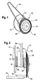
- Fig. 1 shows a part of a high-performance Slicers whose base frame is symbolized by the component 10.
- a circular blade head 12 with a disc-shaped circular blade 14 and a cover member 16 associated with the circular blade 14 is mounted on the base frame 10.
- the cover member 16 is formed as a hood-like or plate-like curved, tight against the circular blade 14 cover and extends radially into the region of the cutting edge 18 of the circular blade 14. Thus, one side of the circular blade 14 is almost completely covered by the cover 16.
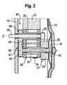
- the circular blade 14 is planetary driven, as described below with reference to FIGS Fig. 2 and 3 is explained in more detail.
- a central hollow shaft member 20 is attached, which defines a central axis Z.
- an eccentric 22 is rotatably mounted on the central hollow shaft member 20.
- An eccentric hollow shaft element 24 is mounted laterally offset from the center axis Z in the eccentric disk 22 and defines a knife axis M.
- the circular blade 14 is fastened to the eccentric hollow shaft element 24.
- a drive shaft member 26, which is driven by a motor, not shown, is passed through the central hollow shaft member 20 and carries a first drive pulley 28.
- the first drive pulley 28 is connected via a toothed belt 29 in engagement with a second drive pulley 30, which is rotatably attached to the eccentric hollow shaft member 24 or formed integrally therewith.
- the arrangement of drive shaft element 26, first and second drive pulley 28, 30 and toothed belt 29 thus forms a first drive 32, which provides for a rotational movement of the circular blade 14 about the blade axis M.
- the eccentric disc 22 is in engagement with an eccentric toothed belt 34, which is drivable via an arrangement of motor and pulley, not shown.
- the eccentric 22 can be driven to rotate about the central axis Z. Due to the eccentric mounting of the circular blade 14, a rotation of the eccentric disc 22 causes a circular movement of the circular blade 14 on a circular path about the central axis Z.
- the arrangement of eccentric toothed belt 34 and eccentric disc 22 is thus associated with a second drive 36, which is for a circulating movement of the circular blade 14 about the central axis Z ensures. Since the revolution and the rotational movement are decoupled from each other and are driven separately, the respective speeds are freely adjustable.
- an auxiliary drive 40 is provided, which is derived from the second drive 36 and includes a guide belt drive 47 for controlled guidance of the cover 16.
- the cover 16 is rotatably mounted for this purpose on a support shaft member 42 which is passed through the eccentric hollow shaft member 24 and at one of the cover 16 opposite end rotatably connected to a first guide pulley 44.
- a guide toothed belt 45 Via a guide toothed belt 45, the first guide pulley 44 is in engagement with a second guide pulley 46, which is non-rotatably mounted on the central hollow shaft member 20 or integrally formed therewith.
- the auxiliary drive 40 is thus formed by the arrangement of carrier shaft member 42, first guide pulley 44, guide toothed belt 45 and second guide pulley 46 and is integrated in the circular blade head 12.
- the first guide pulley 44 rolls on the guide toothed belt 45, which in turn passes over the frame-fixed second guide pulley 46.
- the cover 16 thus experiences a resulting from the orbital motion of the carrier shaft member 42 rotary positive drive.
- Fig. 3 As can be seen, the diameters of the first guide pulley 44 and the second guide pulley 46 are the same size, so that there is a transmission ratio of 1 for the guide belt drive 47. This has the consequence that the cover 16 during the orbital movement relative to a product bar to be sliced 50 (FIG. Fig. 2 ) does not perform its own rotation about the knife axis M. Should the particular application a certain rotation of the cover However, a different gear ratio for the guide belt drive 47 may be selected.
- the circular blade 14 in its orbit approaches the product bar 50 to be sliced, which is located on a product feeder 52 and automatically advanced by means of a controlled drive (not shown).
- the cutting edge 18 of the circular blade 14 separates a product slice 55 from the product bar 50.
- the cover 16 ensures that the separated product disc 55 does not adhere to the rotating circular blade 14, but is stripped on the surface of the cover 16.
- the convex curvature of the cover 16 supports the controlled stripping of the product disk 55.
- circumferential projections 60 are provided on the surface of the cover. Due to the self-rotation of the cover 16 which is reliably prevented by the additional drive 40, an exact and reproducible storage behavior is ensured.
- the separated product slice 55 drops exactly in position from the cover 16 and can be further processed in the desired manner, in particular an automatic storage, transport and / or packaging line fed.
- auxiliary drive 40 for the cover 16 is derived directly from the drive 36 of the circular blade 14, resulting in a simple, inexpensive and highly reliable way of speed control for the cover 16. A separate motor including the associated control is not necessary.
Landscapes
- Life Sciences & Earth Sciences (AREA)
- Forests & Forestry (AREA)
- Engineering & Computer Science (AREA)
- Mechanical Engineering (AREA)
- Food-Manufacturing Devices (AREA)
- Knives (AREA)
Description
- Die vorliegende Erfindung betrifft eine Schneidvorrichtung zum Aufschneiden von Lebensmittelprodukten, insbesondere einen Hochleistungs-Slicer, mit einem antreibbaren Kreismesser, das um eine Messerachse rotiert, die auf einer Bahn um eine Mittelachse umläuft, und einem an der von einem aufzuschneidenden Produkt abgewandten Seite des Kreismessers vorgesehenen, relativ zu dem Kreismesser drehbaren Abdeckelement.
- Das Abdeckelement dient bei derartigen Schneidvorrichtungen dazu, ein störendes Anhaften von abgetrennten Produktscheiben am Kreismesser zu verhindern. Beispielsweise kann das Abdeckelement als eine flache, zu dem Kreismesser koaxiale Scheibe ausgebildet sein. Abgetrennte Produktscheiben treten in Kontakt mit der Scheibe und werden daran abgestreift. Auf diese Weise können auch relativ weiche Lebensmittelprodukte mit hoher Schnittfolge aufgeschnitten werden. Eine Schneidvorrichtung mit einem Abdeckelement ist beispielsweise aus der
EP 0 169 399 B1 bekannt. Die dort offenbarte Abdeckscheibe ist mit einem Antrieb verbunden und kann mit einstellbarer Drehzahl rotiert werden, um eine Relativdrehung zwischen Kreismesser und Abdeckscheibe vorzusehen. Eine derartige Relativdrehung kann zur gezielten Beeinflussung der Schnittgutpositionierung eingesetzt werden. - Das Vorsehen eines eigenständigen Antriebs für das Abdeckelement ist jedoch mit einem relativ hohen Aufwand verbunden. Zudem kann es schwierig sein, den Antrieb in geeigneter Weise unterzubringen. Problematisch ist auch die Ansteuerung eines derartigen Antriebs, da zu jedem Zeitpunkt die korrekte Drehzahldifferenz zwischen der Abdeckscheibe und dem Kreismesser eingeregelt werden muss.
-
GB 369 091 A - Es ist eine Aufgabe der Erfindung, eine Schneidvorrichtung der genannten Art hinsichtlich des Aufwands, des Platzbedarfs und der Zuverlässigkeit zu verbessern.
- Diese Aufgabe wird durch eine Schneidvorrichtung mit den Merkmalen des Anspruchs 1 gelöst. Erfindungsgemäß ist das Abdeckelement durch einen Zusatzantrieb derart angetrieben, dass es sich relativ zu dem Kreismesser um die Messerachse dreht, wobei der Zusatzantrieb von einem Antrieb des Kreismessers abgeleitet ist. Es ist also kein eigenständiger und separat anzusteuernder Antrieb für das Abdeckelement vorgesehen, sondern es wird der ohnehin vorhandene Antrieb des Kreismessers dazu herangezogen, das Abdeckelement in der gewünschten Weise zu bewegen. Erfindungsgemäß wurde erkannt, dass durch einen von einem Antrieb des Kreismessers abgeleiteten Zusatzantrieb nicht nur Kosten eingespart werden können, sondern auch allgemein eine Verbesserung der Zuverlässigkeit und eine Verringerung der Fehleranfälligkeit zu erzielen ist. Insbesondere ist bei einer Schneidvorrichtung gemäß der Erfindung ausgeschlossen, dass durch einen Ausfall des Antriebs des Abdeckelements oder dessen Steuerung das Abdeckelement in eine unkontrollierte Eigenrotation gerät und somit die Ablage der abgetrennten Produktscheiben nicht mehr in der gewünschten Weise erfolgt. Der Zusatzantrieb ist dazu ausgebildet, während der Umlaufbewegung eine Eigenrotation des Abdeckelements um die Messerachse relativ zu dem aufzuschneidenden Produkt zu verhindern. Es wird somit vermieden, dass eine abgetrennte Produktscheibe durch das Abdeckelement mitgenommen und unkontrolliert weggeschleudert wird.
- Weiterbildungen der Erfindung sind in den abhängigen Ansprüchen, der Beschreibung sowie der Zeichnung angegeben.
- Vorzugsweise ist der Zusatzantrieb von einem Antrieb des Kreismessers abgeleitet, der für die Umlaufbewegung um die Mittelachse sorgt. Dadurch kann auf relativ einfache Weise eine Eigenrotation des Abdeckelements während der gesamten Umlaufbewegung unterbunden werden.
- Gemäß einer Ausführungsform ist der Zusatzantrieb durch eine Getriebeanordnung gebildet, die mit dem Antrieb des Kreismessers und mit dem Abdeckelement in Wirkverbindung steht. Durch eine derartige Getriebeanordnung kann sichergestellt werden, dass die Rotationsbewegung des Abdeckelements stets in direktem und unmittelbarem Zusammenhang mit der Bewegung des Kreismessers steht. Durch diese direkte mechanische Kopplung von Kreismesserantrieb und Zusatzantrieb ist eine besonders zuverlässige und ausfallsichere Beeinflussung der Rotation des Abdeckelements möglich.
- Die Getriebeanordnung kann einen Riementrieb, insbesondere einen Zahnriementrieb, mit einer ersten Riemenscheibe, einer zweiten Riemenscheibe und einem Übertragungsriemen umfassen. Ein Riementrieb ist kostengünstig und wartungsfreundlich. Zudem ist ein ruhiger und relativ geräuscharmer Lauf auch bei hohen Umlaufgeschwindigkeiten gewährleistet.
- Der Riementrieb kann insbesondere mit einer relativ zu dem Kreismesser drehbaren und drehfest mit dem Abdeckelement verbundenen Welle in Eingriff stehen. Beispielsweise kann die zweite Riemenscheibe direkt an der entsprechenden Welle befestigt sein. Somit ist einerseits eine drehfeste Verbindung zwischen Abdeckelement und Riemenscheibe und andererseits eine Verdrehbarkeit zwischen Abdeckelement und Kreismesser sichergestellt.
- Gemäß einer Ausführungsform ist das Kreismesser auf einem Hohlwellenelement montiert und die Welle des Abdeckelements ist durch das Hohlwellenelement hindurchgeführt. Auf diese Weise ist eine Entkopplung der Rotationsbewegungen von Kreismesser und Abdeckscheibe trotz gemeinsamer Drehachse möglich.
- Die erste Riemenscheibe kann drehfest mit der Welle des Abdeckelements verbunden sein, während die zweite Riemenscheibe drehfest an einem feststehenden Element, insbesondere an einem Rahmen oder einem Gehäuse der Schneidvorrichtung, angebracht sein kann. Während der Umlaufbewegung des Kreismesserkopfes wälzt sich somit die erste Riemenscheibe an dem Zahnriemen ab, der wiederum mit der gestellfesten zweiten Riemenscheibe in Eingriff steht. Auf diese Weise kann erreicht werden, dass das Abdeckelement während der Umlaufbewegung stets derart weitergedreht wird, dass im Ergebnis keine Eigenrotation relativ zu dem aufzuschneidenden Produkt stattfindet.
- Das Abdeckelement kann eine zu dem Kreismesser koaxiale Scheibe umfassen, die sich radial bis zum Bereich der Schneide des Kreismessers erstreckt. Somit treten die abgetrennten Produktscheiben weitgehend vollflächig mit dem Abdeckelement in Kontakt, wodurch ein sicheres Abstreifen ohne Anhaftungsprobleme am Kreismesser ermöglicht wird.
- Vorzugsweise ist das Abdeckelement an der vom Kreismesser abgewandten Seite mit Erhebungen versehen. Derartige Erhebungen können die Ablage von Produktscheiben weiter verbessern, da ein unerwünschtes Anhaften an dem stillstehenden Abdeckelement verhindert wird.
- Die Erfindung wird im Folgenden unter Bezugnahme auf die Zeichnungen beispielhaft beschrieben.
- Fig. 1
- ist eine schematische Teildarstellung einer erfindungsgemäßen Schneidvorrichtung in Perspektivansicht.
- Fig. 2
- ist eine Seitenansicht der Schneidvorrichtung gemäß
Fig. 1 . - Fig. 3
- ist eine teilweise Schnittansicht der Darstellung gemäß
Fig. 2 . -
Fig. 1 zeigt einen Teil eines Hochleistungs-Slicers, dessen Grundgestell durch das Bauteil 10 symbolisiert ist. Ein Kreismesserkopf 12 mit einem scheibenförmigen Kreismesser 14 und einem dem Kreismesser 14 zugeordneten Abdeckelement 16 ist an dem Grundgestell 10 gelagert. Das Abdeckelement 16 ist als hauben- oder tellerartig gewölbte, eng an dem Kreismesser 14 anliegende Abdeckscheibe ausgebildet und erstreckt sich radial bis in den Bereich der Schneide 18 des Kreismessers 14. Somit ist eine Seite des Kreismessers 14 beinahe vollflächig durch die Abdeckscheibe 16 bedeckt. - Zum Aufschneiden von Lebensmittelprodukten wird das Kreismesser 14 planetarisch umlaufend angetrieben, wie im Folgenden unter Bezugnahme auf die
Fig. 2 und3 näher erläutert wird. - An dem Grundgestell 10 ist ein zentrales Hohlwellenelement 20 angebracht, welches eine Mittelachse Z definiert. Auf dem zentralen Hohlwellenelement 20 ist eine Exzenterscheibe 22 drehbar gelagert. Ein exzentrisches Hohlwellenelement 24 ist seitlich versetzt zu der Mittelachse Z in der Exzenterscheibe 22 gelagert und definiert eine Messerachse M. Das Kreismesser 14 ist an dem exzentrischen Hohlwellenelement 24 befestigt. Ein Antriebswellenelement 26, das durch einen nicht dargestellten Motor antreibbar ist, ist durch das zentrale Hohlwellenelement 20 hindurchgeführt und trägt eine erste Antriebs-Riemenscheibe 28. Die erste Antriebs-Riemenscheibe 28 steht über einen Zahnriemen 29 in Eingriff mit einer zweiten Antriebs-Riemenscheibe 30, welche an dem exzentrischen Hohlwellenelement 24 drehfest angebracht oder einstückig mit diesem ausgebildet ist. Die Anordnung aus Antriebswellenelement 26, erster und zweiter Antriebs-Riemenscheibe 28, 30 sowie Zahnriemen 29 bildet somit einen ersten Antrieb 32, der für eine Rotationsbewegung des Kreismessers 14 um die Messerachse M sorgt.
- Die Exzenterscheibe 22 steht in Eingriff mit einem Exzenter-Zahnriemen 34, der über eine nicht dargestellte Anordnung aus Motor und Riemenscheibe antreibbar ist. Somit kann die Exzenterscheibe 22 um die Mittelachse Z rotierend angetrieben werden. Aufgrund der exzentrischen Lagerung des Kreismessers 14 bewirkt eine Rotation der Exzenterscheibe 22 eine Umlaufbewegung des Kreismessers 14 auf einer Kreisbahn um die Mittelachse Z. Die Anordnung aus Exzenter-Zahnriemen 34 und Exzenterscheibe 22 ist somit einem zweiten Antrieb 36 zugeordnet, der für eine Umlaufbewegung des Kreismessers 14 um die Mittelachse Z sorgt. Da die Umlaufbewegung und die Rotationsbewegung voneinander entkoppelt sind und separat angetrieben werden, sind die jeweiligen Drehzahlen beliebig einstellbar.
- Um einer Eigenrotation der Abdeckscheibe 16 um die Messerachse M während des Betriebs der Schneidvorrichtung entgegenzuwirken, ist ein Zusatzantrieb 40 vorgesehen, welcher von dem zweiten Antrieb 36 abgeleitet ist und einen Führungs-Riementrieb 47 zur kontrollierten Führung der Abdeckscheibe 16 umfasst. Die Abdeckscheibe 16 ist zu diesem Zweck drehfest an einem Trägerwellenelement 42 angebracht, welches durch das exzentrische Hohlwellenelement 24 hindurchgeführt ist und an einem der Abdeckscheibe 16 entgegengesetzten Ende drehfest mit einer ersten Führungs-Riemenscheibe 44 verbunden ist. Über einen Führungs-Zahnriemen 45 steht die erste Führungs-Riemenscheibe 44 in Eingriff mit einer zweiten Führungs-Riemenscheibe 46, welche drehfest an dem zentralen Hohlwellenelement 20 angebracht oder einstückig mit diesem ausgebildet ist. Der Zusatzantrieb 40 wird also durch die Anordnung aus Trägerwellenelement 42, erster Führungs-Riemenscheibe 44, Führungs-Zahnriemen 45 und zweiter Führungs-Riemenscheibe 46 gebildet und ist im Kreismesserkopf 12 integriert.
- Während des planetarischen Umlaufs des Kreismessers 14 wälzt sich die erste Führungs-Riemenscheibe 44 auf dem Führungs-Zahnriemen 45 ab, welcher wiederum über die gestellfeste zweite Führungs-Riemenscheibe 46 läuft. Die Abdeckscheibe 16 erfährt somit einen aus der Umlaufbewegung des Trägerwellenelements 42 resultierenden rotatorischen Zwangsantrieb. Wie aus
Fig. 3 hervorgeht, sind die Durchmesser der ersten Führungs-Riemenscheibe 44 und der zweiten Führungs-Riemenscheibe 46 gleich groß, sodass sich für den Führungs-Riementrieb 47 ein Übersetzungsverhältnis von 1 ergibt. Dies hat zur Folge, dass die Abdeckscheibe 16 während der Umlaufbewegung relativ zu einem aufzuschneidenden Produktriegel 50 (Fig. 2 ) keine Eigenrotation um die Messerachse M ausführt. Sollte die jeweilige Anwendung eine bestimmte Drehung der Abdeckscheibe 16 um sich selbst erfordern, so kann jedoch auch ein anderes Übersetzungsverhältnis für den Führungs-Riementrieb 47 gewählt werden. - Während des Betriebs der Schneidvorrichtung nähert sich das Kreismesser 14 auf seiner Umlaufbahn dem aufzuschneidenden Produktriegel 50, der sich auf einer Produktzuführung 52 befindet und mittels eines gesteuerten Antriebs (nicht dargestellt) automatisch vorgeschoben wird. Im weiteren Verlauf der planetarischen Umlaufbewegung trennt die Schneide 18 des Kreismessers 14 eine Produktscheibe 55 von dem Produktriegel 50 ab. Die Abdeckscheibe 16 sorgt dafür, dass die abgetrennte Produktscheibe 55 nicht an dem rotierenden Kreismesser 14 haften bleibt, sondern an der Oberfläche der Abdeckscheibe 16 abgestreift wird. Die konvexe Wölbung der Abdeckscheibe 16 unterstützt das kontrollierte Abstreifen der Produktscheibe 55. Zur weiteren Verbesserung des Abstreifvorgangs sind an der Oberfläche der Abdeckscheibe 16 umlaufende Erhebungen 60 vorgesehen. Aufgrund der durch den Zusatzantrieb 40 sicher verhinderten Eigenrotation der Abdeckscheibe 16 ist ein exaktes und reproduzierbares Ablageverhalten gewährleistet. Die abgetrennte Produktscheibe 55 fällt positionsgenau von der Abdeckscheibe 16 ab und kann in gewünschter Weise weiterverarbeitet, insbesondere einer automatischen Ablage-, Transport- und/oder Verpackungslinie zugeführt, werden.
- Anstelle des Führungs-Riementriebs 47 könnten verschiedene andere Getriebeanordnungen, wie beispielsweise ein Zahnradgetriebe, eingesetzt werden.
- Dadurch, dass der Zusatzantrieb 40 für die Abdeckscheibe 16 direkt von dem Antrieb 36 des Kreismessers 14 abgeleitet ist, ergibt sich eine einfache, kostengünstige und äußerst zuverlässige Art der Drehzahlbeeinflussung für die Abdeckscheibe 16. Ein separater Motor einschließlich der zugehörigen Steuerung ist nicht notwendig.
-
- 10
- Grundgestell
- 12
- Kreismesserkopf
- 14
- Kreismesser
- 16
- Abdeckscheibe
- 18
- Schneide
- 20
- zentrales Hohlwellenelement
- 22
- Exzenterscheibe
- 24
- exzentrisches Hohlwellenelement
- 26
- Antriebswellenelement
- 28
- erste Antriebs-Riemenscheibe
- 29
- Zahnriemen
- 30
- zweite Antriebs-Riemenscheibe
- 32
- erster Antrieb
- 34
- Exzenter-Zahnriemen
- 36
- zweiter Antrieb
- 40
- Zusatzantrieb
- 42
- Trägerwellenelement
- 44
- erste Führungs-Riemenscheibe
- 45
- Führungs-Zahnriemen
- 46
- zweite Führungs-Riemenscheibe
- 47
- Führungs-Riementrieb
- 50
- Produktriegel
- 52
- Produktzuführung
- 55
- Produktscheibe
- 60
- Erhebung
- Z
- Mittelachse
- M
- Messerachse
Claims (10)
- Schneidvorrichtung zum Aufschneiden von Lebensmittelprodukten, insbesondere Hochleistungs-Slicer, mit
einem antreibbaren Kreismesser (14), das um eine Messerachse (M) rotiert, die auf einer Bahn um eine Mittelachse (Z) umläuft, und einem an der von einem aufzuschneidenden Produkt (50) abgewandten Seite des Kreismessers (14) vorgesehenen, relativ zu dem Kreismesser (14) drehbaren Abdeckelement (16),
dadurch gekennzeichnet,
dass das Abdeckelement (16) durch einen Zusatzantrieb (40) derart angetrieben ist, dass es sich relativ zu dem Kreismesser (14) um die Messerachse (M) dreht,
wobei der Zusatzantrieb (40) von einem Antrieb (32, 36) des Kreismessers (14) abgeleitet ist und dazu ausgebildet ist, während der Umlaufbewegung eine Eigenrotation des Abdeckelements (16) um die Messerachse (M) relativ zu dem aufzuschneidenden Produkt (50) zu verhindern. - Vorrichtung nach Anspruch 1,
dadurch gekennzeichnet,
dass der Zusatzantrieb (40) von einem Antrieb (36) des Kreismessers (14) abgeleitet ist, der für die Umlaufbewegung um die Mittelachse (Z) sorgt. - Vorrichtung nach Anspruch 1 oder 2,
dadurch gekennzeichnet,
dass der Zusatzantrieb (40) durch eine Getriebeanordnung gebildet ist, die mit dem Antrieb (32, 36) des Kreismessers (14) und mit dem Abdeckelement (16) in Wirkverbindung steht. - Vorrichtung nach Anspruch 3,
dadurch gekennzeichnet,
dass die Getriebeanordnung einen Riementrieb (47), insbesondere einen Zahnriementrieb, mit einer ersten Riemenscheibe (44), einer zweiten Riemenscheibe (46) und einem Übertragungsriemen (45),
umfasst. - Vorrichtung nach Anspruch 4,
dadurch gekennzeichnet,
dass der Riementrieb (47) mit einer relativ zu dem Kreismesser (14) drehbaren und drehfest mit dem Abdeckelement (16) verbundenen Welle (42) in Eingriff steht. - Vorrichtung nach Anspruch 5,
dadurch gekennzeichnet,
dass das Kreismesser (14) auf einem Hohlwellenelement (24) montiert ist und die Welle (42) des Abdeckelements (16) durch das Hohlwellenelement (24) hindurchgeführt ist. - Vorrichtung nach Anspruch 5 oder 6,
dadurch gekennzeichnet,
dass die erste Riemenscheibe (44) drehfest mit der Welle (42) des Abdeckelements (16) verbunden ist. - Vorrichtung nach zumindest einem der Ansprüche 4 bis 7,
dadurch gekennzeichnet,
dass die zweite Riemenscheibe (46) drehfest an einem feststehenden Element (10), insbesondere an einem Rahmen oder einem Gehäuse der Schneidvorrichtung, angebracht ist. - Vorrichtung nach zumindest einem der vorstehenden Ansprüche,
dadurch gekennzeichnet,
dass das Abdeckelement (16) eine zu dem Kreismesser (14) koaxiale Scheibe umfasst, die sich radial bis zum Bereich der Schneide (18) des Kreismessers (14) erstreckt. - Vorrichtung nach zumindest einem der vorstehenden Ansprüche,
dadurch gekennzeichnet,
dass das Abdeckelement (16) an der vom Kreismesser (14) abgewandten Seite mit Erhebungen (60) versehen ist.
Applications Claiming Priority (2)
| Application Number | Priority Date | Filing Date | Title |
|---|---|---|---|
| DE200910011399 DE102009011399A1 (de) | 2009-03-03 | 2009-03-03 | Schneidvorrichtung |
| PCT/EP2010/000850 WO2010099856A1 (de) | 2009-03-03 | 2010-02-11 | Schneidvorrichtung |
Publications (2)
| Publication Number | Publication Date |
|---|---|
| EP2403694A1 EP2403694A1 (de) | 2012-01-11 |
| EP2403694B1 true EP2403694B1 (de) | 2014-11-19 |
Family
ID=42136337
Family Applications (1)
| Application Number | Title | Priority Date | Filing Date |
|---|---|---|---|
| EP20100704511 Not-in-force EP2403694B1 (de) | 2009-03-03 | 2010-02-11 | Schneidvorrichtung |
Country Status (4)
| Country | Link |
|---|---|
| US (1) | US8596175B2 (de) |
| EP (1) | EP2403694B1 (de) |
| DE (1) | DE102009011399A1 (de) |
| WO (1) | WO2010099856A1 (de) |
Families Citing this family (10)
| Publication number | Priority date | Publication date | Assignee | Title |
|---|---|---|---|---|
| DE102012004960A1 (de) * | 2012-03-14 | 2013-09-19 | GEA CFS Bühl GmbH | Schneidmesser mit einem Mittel zur Erzeugung eines Luftstroms |
| JP2016026890A (ja) * | 2014-06-25 | 2016-02-18 | 株式会社日本キャリア工業 | 食肉スライサー |
| US9950869B1 (en) | 2017-01-04 | 2018-04-24 | Provisur Technologies, Inc. | Belt tensioner in a food processing machine |
| US10836065B2 (en) | 2017-01-04 | 2020-11-17 | Provisur Technologies, Inc. | Exposed load cell in a food processing machine |
| US10160602B2 (en) | 2017-01-04 | 2018-12-25 | Provisur Technologies, Inc. | Configurable in-feed for a food processing machine |
| US10639798B2 (en) | 2017-01-04 | 2020-05-05 | Provisur Technologies, Inc. | Gripper actuating system in a food processing machine |
| ES2920155T3 (es) * | 2018-03-09 | 2022-08-01 | Gea Food Solutions Germany Gmbh | Receptáculo de cuchilla para un dispositivo para cortar productos alimenticios |
| DE102018005934A1 (de) * | 2018-07-30 | 2020-01-30 | Siller Holding GmbH | Motorischer Antrieb für eine Schneidmaschine |
| CN111571650B (zh) * | 2020-05-26 | 2021-08-06 | 浙江大舜扣多多智能科技股份有限公司 | 一种树脂光学材料制造加工工艺 |
| EP4460413A4 (de) | 2022-04-29 | 2026-04-08 | Provisur Technologies Inc | Lebensmittelproduktschneidvorrichtung mit produktverschlussanordnung und verfahren zum betrieb davon |
Family Cites Families (15)
| Publication number | Priority date | Publication date | Assignee | Title |
|---|---|---|---|---|
| DE86577C (de) | ||||
| GB369091A (en) | 1931-06-16 | 1932-03-17 | Berkel & Parnall Mach Mfg Co | Improvements in or relating to slicing machines |
| US2479182A (en) * | 1945-12-28 | 1949-08-16 | Adolf M Peters | Slicing machine |
| US3353430A (en) * | 1965-08-24 | 1967-11-21 | American Mach & Foundry | High speed cigarette cutoff |
| DD86577A1 (de) * | 1970-11-17 | 1971-12-12 | Aufschnittschneidemaschine | |
| DE7611681U1 (de) * | 1976-04-13 | 1976-09-09 | Fa. Robert Krups, 5650 Solingen | Haushaltsschneidemaschine, insbesondere mit elektromotorischem antrieb |
| DE3427116A1 (de) | 1984-07-23 | 1986-01-23 | Guenther Weber | Aufschnitt-schneidevorrichtung |
| US4685364A (en) | 1985-05-17 | 1987-08-11 | Bettcher Industries, Inc. | Rotary slicer for comestible products |
| DE3713536A1 (de) * | 1987-04-22 | 1988-11-10 | Guenther Weber | Antriebs- und lageranordnung fuer den schneidkopf einer circularschneidmaschine |
| JPH0711859Y2 (ja) * | 1990-03-02 | 1995-03-22 | 大見工業株式会社 | 回転カッターの制振装置 |
| DE19820004C2 (de) | 1998-05-06 | 2000-06-08 | Uwe Reifenhaeuser | Maschine zum Schneiden eines Gutsstrangs in Scheiben |
| GB9815206D0 (en) * | 1998-07-15 | 1998-09-09 | Gec Avery Ltd | Knife assembly |
| KR100319131B1 (ko) * | 1999-06-14 | 2001-12-29 | 정운조 | 식품 슬라이서의 절단편 이탈 안내장치 |
| IT1314595B1 (it) * | 2000-03-28 | 2002-12-20 | Perini Fabio Spa | Troncatrice multipla per prodotti in materiale nastriforme con unazona di affilatura delle lame separata dalla zona di taglio |
| DE102005062501B4 (de) | 2005-12-16 | 2009-10-22 | Bizerba Gmbh & Co. Kg | Lebensmittelschneidemaschine |
-
2009
- 2009-03-03 DE DE200910011399 patent/DE102009011399A1/de not_active Withdrawn
-
2010
- 2010-02-11 WO PCT/EP2010/000850 patent/WO2010099856A1/de not_active Ceased
- 2010-02-11 US US13/254,739 patent/US8596175B2/en not_active Expired - Fee Related
- 2010-02-11 EP EP20100704511 patent/EP2403694B1/de not_active Not-in-force
Also Published As
| Publication number | Publication date |
|---|---|
| DE102009011399A1 (de) | 2010-09-09 |
| US8596175B2 (en) | 2013-12-03 |
| US20120060663A1 (en) | 2012-03-15 |
| WO2010099856A1 (de) | 2010-09-10 |
| EP2403694A1 (de) | 2012-01-11 |
Similar Documents
| Publication | Publication Date | Title |
|---|---|---|
| EP2403694B1 (de) | Schneidvorrichtung | |
| DE112017004840B4 (de) | Rotative Abisoliervorrichtung | |
| EP2628424B1 (de) | Elektromotorisch betriebene Küchenmaschine | |
| EP0509230B1 (de) | Vorschubantrieb für eine Schneidemaschine zum Schneiden von Lebensmittelprodukten | |
| EP2258522B1 (de) | Vorrichtung zum Schneiden eines kontinuierlich geführten Strangs in strangförmige Artikel variabler Länge sowie Strangmaschine mit einer solchen Vorrichtung | |
| EP2374584B1 (de) | Vorrichtung zum Aufschneiden von Lebensmittelprodukten | |
| EP2226170B1 (de) | Zuführkettenrahmen für automatische Scheibenschneidemaschinen | |
| EP0495239A1 (de) | Schneidmaschine zur wahlweisen Verwendung als Scheiben-, Streifen- oder Würfelschneidemaschine | |
| EP3957448B1 (de) | Kreismesservorrichtung | |
| EP2374581B1 (de) | Vorrichtung zum Aufschneiden von Lebensmittelprodukten | |
| EP3127525B1 (de) | Patientenauflage mit koppelbaren auflageteilen | |
| WO2019037897A1 (de) | Längsschneidevorrichtung | |
| EP2403693B1 (de) | Schneidvorrichtung | |
| EP1260325B1 (de) | Dreimesserschneidemaschine | |
| EP3597383B1 (de) | Scheibenschneidemaschine mit werkzeugfrei auswechselbarem schneidrahmen | |
| DE102010019744B4 (de) | Vorrichtung zum Aufschneiden von Lebensmittelprodukten | |
| EP1623946A2 (de) | Falzapparate | |
| EP1099502B1 (de) | Hochgeschwindigkeitsschere zum Querteilen von insbesondere dünnem Walzband | |
| EP2279145B1 (de) | Falzvorrichtung mit vor- oder nachgelagerten messer- oder vergleichbaren werkzeugwellen | |
| DE69925947T2 (de) | Vorrichtung zum Perforieren | |
| DE2441225B2 (de) | Vorrichtung zum Bearbeiten von kontinuierlich durchlaufenden mehrschichtigen Papierbahnen | |
| DE2251567A1 (de) | Hochleistungs-kaeseschneidmaschine | |
| EP1594663A1 (de) | Längsschneideeinrichtung zum schneiden von laufenden materialbahnen | |
| DE102010011172A1 (de) | Vorrichtung zum Aufschneiden von Lebensmittelprodukten | |
| EP3603908B1 (de) | Motorischer antrieb für eine schneidmaschine |
Legal Events
| Date | Code | Title | Description |
|---|---|---|---|
| PUAI | Public reference made under article 153(3) epc to a published international application that has entered the european phase |
Free format text: ORIGINAL CODE: 0009012 |
|
| 17P | Request for examination filed |
Effective date: 20110830 |
|
| AK | Designated contracting states |
Kind code of ref document: A1 Designated state(s): AT BE BG CH CY CZ DE DK EE ES FI FR GB GR HR HU IE IS IT LI LT LU LV MC MK MT NL NO PL PT RO SE SI SK SM TR |
|
| DAX | Request for extension of the european patent (deleted) | ||
| GRAP | Despatch of communication of intention to grant a patent |
Free format text: ORIGINAL CODE: EPIDOSNIGR1 |
|
| INTG | Intention to grant announced |
Effective date: 20140620 |
|
| GRAS | Grant fee paid |
Free format text: ORIGINAL CODE: EPIDOSNIGR3 |
|
| GRAA | (expected) grant |
Free format text: ORIGINAL CODE: 0009210 |
|
| AK | Designated contracting states |
Kind code of ref document: B1 Designated state(s): AT BE BG CH CY CZ DE DK EE ES FI FR GB GR HR HU IE IS IT LI LT LU LV MC MK MT NL NO PL PT RO SE SI SK SM TR |
|
| REG | Reference to a national code |
Ref country code: GB Ref legal event code: FG4D Free format text: NOT ENGLISH |
|
| REG | Reference to a national code |
Ref country code: CH Ref legal event code: EP |
|
| REG | Reference to a national code |
Ref country code: AT Ref legal event code: REF Ref document number: 696720 Country of ref document: AT Kind code of ref document: T Effective date: 20141215 |
|
| REG | Reference to a national code |
Ref country code: IE Ref legal event code: FG4D Free format text: LANGUAGE OF EP DOCUMENT: GERMAN |
|
| REG | Reference to a national code |
Ref country code: DE Ref legal event code: R096 Ref document number: 502010008281 Country of ref document: DE Effective date: 20141231 |
|
| REG | Reference to a national code |
Ref country code: NL Ref legal event code: VDEP Effective date: 20141119 |
|
| REG | Reference to a national code |
Ref country code: LT Ref legal event code: MG4D |
|
| PG25 | Lapsed in a contracting state [announced via postgrant information from national office to epo] |
Ref country code: PT Free format text: LAPSE BECAUSE OF FAILURE TO SUBMIT A TRANSLATION OF THE DESCRIPTION OR TO PAY THE FEE WITHIN THE PRESCRIBED TIME-LIMIT Effective date: 20150319 Ref country code: ES Free format text: LAPSE BECAUSE OF FAILURE TO SUBMIT A TRANSLATION OF THE DESCRIPTION OR TO PAY THE FEE WITHIN THE PRESCRIBED TIME-LIMIT Effective date: 20141119 Ref country code: LT Free format text: LAPSE BECAUSE OF FAILURE TO SUBMIT A TRANSLATION OF THE DESCRIPTION OR TO PAY THE FEE WITHIN THE PRESCRIBED TIME-LIMIT Effective date: 20141119 Ref country code: FI Free format text: LAPSE BECAUSE OF FAILURE TO SUBMIT A TRANSLATION OF THE DESCRIPTION OR TO PAY THE FEE WITHIN THE PRESCRIBED TIME-LIMIT Effective date: 20141119 Ref country code: IS Free format text: LAPSE BECAUSE OF FAILURE TO SUBMIT A TRANSLATION OF THE DESCRIPTION OR TO PAY THE FEE WITHIN THE PRESCRIBED TIME-LIMIT Effective date: 20150319 Ref country code: NO Free format text: LAPSE BECAUSE OF FAILURE TO SUBMIT A TRANSLATION OF THE DESCRIPTION OR TO PAY THE FEE WITHIN THE PRESCRIBED TIME-LIMIT Effective date: 20150219 Ref country code: NL Free format text: LAPSE BECAUSE OF FAILURE TO SUBMIT A TRANSLATION OF THE DESCRIPTION OR TO PAY THE FEE WITHIN THE PRESCRIBED TIME-LIMIT Effective date: 20141119 |
|
| PG25 | Lapsed in a contracting state [announced via postgrant information from national office to epo] |
Ref country code: GR Free format text: LAPSE BECAUSE OF FAILURE TO SUBMIT A TRANSLATION OF THE DESCRIPTION OR TO PAY THE FEE WITHIN THE PRESCRIBED TIME-LIMIT Effective date: 20150220 Ref country code: CY Free format text: LAPSE BECAUSE OF FAILURE TO SUBMIT A TRANSLATION OF THE DESCRIPTION OR TO PAY THE FEE WITHIN THE PRESCRIBED TIME-LIMIT Effective date: 20141119 Ref country code: SE Free format text: LAPSE BECAUSE OF FAILURE TO SUBMIT A TRANSLATION OF THE DESCRIPTION OR TO PAY THE FEE WITHIN THE PRESCRIBED TIME-LIMIT Effective date: 20141119 Ref country code: HR Free format text: LAPSE BECAUSE OF FAILURE TO SUBMIT A TRANSLATION OF THE DESCRIPTION OR TO PAY THE FEE WITHIN THE PRESCRIBED TIME-LIMIT Effective date: 20141119 Ref country code: LV Free format text: LAPSE BECAUSE OF FAILURE TO SUBMIT A TRANSLATION OF THE DESCRIPTION OR TO PAY THE FEE WITHIN THE PRESCRIBED TIME-LIMIT Effective date: 20141119 Ref country code: PL Free format text: LAPSE BECAUSE OF FAILURE TO SUBMIT A TRANSLATION OF THE DESCRIPTION OR TO PAY THE FEE WITHIN THE PRESCRIBED TIME-LIMIT Effective date: 20141119 |
|
| PG25 | Lapsed in a contracting state [announced via postgrant information from national office to epo] |
Ref country code: CZ Free format text: LAPSE BECAUSE OF FAILURE TO SUBMIT A TRANSLATION OF THE DESCRIPTION OR TO PAY THE FEE WITHIN THE PRESCRIBED TIME-LIMIT Effective date: 20141119 Ref country code: SK Free format text: LAPSE BECAUSE OF FAILURE TO SUBMIT A TRANSLATION OF THE DESCRIPTION OR TO PAY THE FEE WITHIN THE PRESCRIBED TIME-LIMIT Effective date: 20141119 Ref country code: RO Free format text: LAPSE BECAUSE OF FAILURE TO SUBMIT A TRANSLATION OF THE DESCRIPTION OR TO PAY THE FEE WITHIN THE PRESCRIBED TIME-LIMIT Effective date: 20141119 Ref country code: EE Free format text: LAPSE BECAUSE OF FAILURE TO SUBMIT A TRANSLATION OF THE DESCRIPTION OR TO PAY THE FEE WITHIN THE PRESCRIBED TIME-LIMIT Effective date: 20141119 Ref country code: DK Free format text: LAPSE BECAUSE OF FAILURE TO SUBMIT A TRANSLATION OF THE DESCRIPTION OR TO PAY THE FEE WITHIN THE PRESCRIBED TIME-LIMIT Effective date: 20141119 |
|
| REG | Reference to a national code |
Ref country code: DE Ref legal event code: R097 Ref document number: 502010008281 Country of ref document: DE |
|
| PLBE | No opposition filed within time limit |
Free format text: ORIGINAL CODE: 0009261 |
|
| STAA | Information on the status of an ep patent application or granted ep patent |
Free format text: STATUS: NO OPPOSITION FILED WITHIN TIME LIMIT |
|
| PG25 | Lapsed in a contracting state [announced via postgrant information from national office to epo] |
Ref country code: LU Free format text: LAPSE BECAUSE OF FAILURE TO SUBMIT A TRANSLATION OF THE DESCRIPTION OR TO PAY THE FEE WITHIN THE PRESCRIBED TIME-LIMIT Effective date: 20150211 |
|
| REG | Reference to a national code |
Ref country code: CH Ref legal event code: PL |
|
| 26N | No opposition filed |
Effective date: 20150820 |
|
| PG25 | Lapsed in a contracting state [announced via postgrant information from national office to epo] |
Ref country code: CH Free format text: LAPSE BECAUSE OF NON-PAYMENT OF DUE FEES Effective date: 20150228 Ref country code: LI Free format text: LAPSE BECAUSE OF NON-PAYMENT OF DUE FEES Effective date: 20150228 Ref country code: MC Free format text: LAPSE BECAUSE OF FAILURE TO SUBMIT A TRANSLATION OF THE DESCRIPTION OR TO PAY THE FEE WITHIN THE PRESCRIBED TIME-LIMIT Effective date: 20141119 |
|
| REG | Reference to a national code |
Ref country code: IE Ref legal event code: MM4A |
|
| REG | Reference to a national code |
Ref country code: FR Ref legal event code: ST Effective date: 20151030 |
|
| PG25 | Lapsed in a contracting state [announced via postgrant information from national office to epo] |
Ref country code: IT Free format text: LAPSE BECAUSE OF FAILURE TO SUBMIT A TRANSLATION OF THE DESCRIPTION OR TO PAY THE FEE WITHIN THE PRESCRIBED TIME-LIMIT Effective date: 20141119 |
|
| PG25 | Lapsed in a contracting state [announced via postgrant information from national office to epo] |
Ref country code: IE Free format text: LAPSE BECAUSE OF NON-PAYMENT OF DUE FEES Effective date: 20150211 |
|
| PG25 | Lapsed in a contracting state [announced via postgrant information from national office to epo] |
Ref country code: SI Free format text: LAPSE BECAUSE OF FAILURE TO SUBMIT A TRANSLATION OF THE DESCRIPTION OR TO PAY THE FEE WITHIN THE PRESCRIBED TIME-LIMIT Effective date: 20141119 Ref country code: FR Free format text: LAPSE BECAUSE OF NON-PAYMENT OF DUE FEES Effective date: 20150302 |
|
| REG | Reference to a national code |
Ref country code: AT Ref legal event code: MM01 Ref document number: 696720 Country of ref document: AT Kind code of ref document: T Effective date: 20150211 |
|
| PG25 | Lapsed in a contracting state [announced via postgrant information from national office to epo] |
Ref country code: AT Free format text: LAPSE BECAUSE OF NON-PAYMENT OF DUE FEES Effective date: 20150211 |
|
| PG25 | Lapsed in a contracting state [announced via postgrant information from national office to epo] |
Ref country code: MT Free format text: LAPSE BECAUSE OF FAILURE TO SUBMIT A TRANSLATION OF THE DESCRIPTION OR TO PAY THE FEE WITHIN THE PRESCRIBED TIME-LIMIT Effective date: 20141119 |
|
| PG25 | Lapsed in a contracting state [announced via postgrant information from national office to epo] |
Ref country code: HU Free format text: LAPSE BECAUSE OF FAILURE TO SUBMIT A TRANSLATION OF THE DESCRIPTION OR TO PAY THE FEE WITHIN THE PRESCRIBED TIME-LIMIT; INVALID AB INITIO Effective date: 20100211 Ref country code: BG Free format text: LAPSE BECAUSE OF FAILURE TO SUBMIT A TRANSLATION OF THE DESCRIPTION OR TO PAY THE FEE WITHIN THE PRESCRIBED TIME-LIMIT Effective date: 20141119 Ref country code: SM Free format text: LAPSE BECAUSE OF FAILURE TO SUBMIT A TRANSLATION OF THE DESCRIPTION OR TO PAY THE FEE WITHIN THE PRESCRIBED TIME-LIMIT Effective date: 20141119 |
|
| PG25 | Lapsed in a contracting state [announced via postgrant information from national office to epo] |
Ref country code: BE Free format text: LAPSE BECAUSE OF NON-PAYMENT OF DUE FEES Effective date: 20150228 |
|
| PG25 | Lapsed in a contracting state [announced via postgrant information from national office to epo] |
Ref country code: TR Free format text: LAPSE BECAUSE OF FAILURE TO SUBMIT A TRANSLATION OF THE DESCRIPTION OR TO PAY THE FEE WITHIN THE PRESCRIBED TIME-LIMIT Effective date: 20141119 |
|
| PGFP | Annual fee paid to national office [announced via postgrant information from national office to epo] |
Ref country code: GB Payment date: 20180221 Year of fee payment: 9 |
|
| PG25 | Lapsed in a contracting state [announced via postgrant information from national office to epo] |
Ref country code: MK Free format text: LAPSE BECAUSE OF FAILURE TO SUBMIT A TRANSLATION OF THE DESCRIPTION OR TO PAY THE FEE WITHIN THE PRESCRIBED TIME-LIMIT Effective date: 20141119 |
|
| GBPC | Gb: european patent ceased through non-payment of renewal fee |
Effective date: 20190211 |
|
| PG25 | Lapsed in a contracting state [announced via postgrant information from national office to epo] |
Ref country code: GB Free format text: LAPSE BECAUSE OF NON-PAYMENT OF DUE FEES Effective date: 20190211 |
|
| PGFP | Annual fee paid to national office [announced via postgrant information from national office to epo] |
Ref country code: DE Payment date: 20220217 Year of fee payment: 13 |
|
| REG | Reference to a national code |
Ref country code: DE Ref legal event code: R119 Ref document number: 502010008281 Country of ref document: DE |
|
| PG25 | Lapsed in a contracting state [announced via postgrant information from national office to epo] |
Ref country code: DE Free format text: LAPSE BECAUSE OF NON-PAYMENT OF DUE FEES Effective date: 20230901 |