EP2403673B2 - Schaftfräser - Google Patents
Schaftfräser Download PDFInfo
- Publication number
- EP2403673B2 EP2403673B2 EP10713554.3A EP10713554A EP2403673B2 EP 2403673 B2 EP2403673 B2 EP 2403673B2 EP 10713554 A EP10713554 A EP 10713554A EP 2403673 B2 EP2403673 B2 EP 2403673B2
- Authority
- EP
- European Patent Office
- Prior art keywords
- end mill
- chip
- mill cutter
- cutter according
- cutting edges
- Prior art date
- Legal status (The legal status is an assumption and is not a legal conclusion. Google has not performed a legal analysis and makes no representation as to the accuracy of the status listed.)
- Active
Links
- 238000005520 cutting process Methods 0.000 claims description 100
- 238000003801 milling Methods 0.000 claims description 42
- 239000000463 material Substances 0.000 claims description 23
- 230000002093 peripheral effect Effects 0.000 claims description 21
- 238000003754 machining Methods 0.000 claims description 9
- 238000000576 coating method Methods 0.000 claims description 8
- 230000004323 axial length Effects 0.000 claims description 4
- 239000011248 coating agent Substances 0.000 claims description 4
- 239000007787 solid Substances 0.000 claims description 3
- 238000005553 drilling Methods 0.000 claims description 2
- 230000000704 physical effect Effects 0.000 claims description 2
- 230000015572 biosynthetic process Effects 0.000 description 6
- 239000002184 metal Substances 0.000 description 5
- 238000000227 grinding Methods 0.000 description 4
- 238000011161 development Methods 0.000 description 3
- 230000018109 developmental process Effects 0.000 description 3
- 239000002826 coolant Substances 0.000 description 2
- 230000001419 dependent effect Effects 0.000 description 2
- 239000000314 lubricant Substances 0.000 description 2
- 238000004519 manufacturing process Methods 0.000 description 2
- 239000011195 cermet Substances 0.000 description 1
- 239000000470 constituent Substances 0.000 description 1
- 238000010276 construction Methods 0.000 description 1
- 230000007423 decrease Effects 0.000 description 1
- 238000013461 design Methods 0.000 description 1
- 230000000694 effects Effects 0.000 description 1
- 230000002349 favourable effect Effects 0.000 description 1
- 238000012986 modification Methods 0.000 description 1
- 230000004048 modification Effects 0.000 description 1
- 229910052961 molybdenite Inorganic materials 0.000 description 1
- CWQXQMHSOZUFJS-UHFFFAOYSA-N molybdenum disulfide Chemical compound S=[Mo]=S CWQXQMHSOZUFJS-UHFFFAOYSA-N 0.000 description 1
- 229910052982 molybdenum disulfide Inorganic materials 0.000 description 1
- 238000012545 processing Methods 0.000 description 1
- 238000007493 shaping process Methods 0.000 description 1
- 239000007779 soft material Substances 0.000 description 1
- 238000012360 testing method Methods 0.000 description 1
- 230000007704 transition Effects 0.000 description 1
Images


Classifications
-
- B—PERFORMING OPERATIONS; TRANSPORTING
- B23—MACHINE TOOLS; METAL-WORKING NOT OTHERWISE PROVIDED FOR
- B23C—MILLING
- B23C5/00—Milling-cutters
- B23C5/02—Milling-cutters characterised by the shape of the cutter
- B23C5/10—Shank-type cutters, i.e. with an integral shaft
-
- B—PERFORMING OPERATIONS; TRANSPORTING
- B23—MACHINE TOOLS; METAL-WORKING NOT OTHERWISE PROVIDED FOR
- B23C—MILLING
- B23C5/00—Milling-cutters
- B23C5/003—Milling-cutters with vibration suppressing means
-
- B—PERFORMING OPERATIONS; TRANSPORTING
- B23—MACHINE TOOLS; METAL-WORKING NOT OTHERWISE PROVIDED FOR
- B23C—MILLING
- B23C2210/00—Details of milling cutters
- B23C2210/04—Angles
- B23C2210/0485—Helix angles
-
- B—PERFORMING OPERATIONS; TRANSPORTING
- B23—MACHINE TOOLS; METAL-WORKING NOT OTHERWISE PROVIDED FOR
- B23C—MILLING
- B23C2210/00—Details of milling cutters
- B23C2210/04—Angles
- B23C2210/0485—Helix angles
- B23C2210/0492—Helix angles different
-
- B—PERFORMING OPERATIONS; TRANSPORTING
- B23—MACHINE TOOLS; METAL-WORKING NOT OTHERWISE PROVIDED FOR
- B23C—MILLING
- B23C2210/00—Details of milling cutters
- B23C2210/08—Side or top views of the cutting edge
- B23C2210/086—Discontinuous or interrupted cutting edges
-
- B—PERFORMING OPERATIONS; TRANSPORTING
- B23—MACHINE TOOLS; METAL-WORKING NOT OTHERWISE PROVIDED FOR
- B23C—MILLING
- B23C2210/00—Details of milling cutters
- B23C2210/08—Side or top views of the cutting edge
- B23C2210/088—Cutting edges with a wave form
-
- B—PERFORMING OPERATIONS; TRANSPORTING
- B23—MACHINE TOOLS; METAL-WORKING NOT OTHERWISE PROVIDED FOR
- B23C—MILLING
- B23C2210/00—Details of milling cutters
- B23C2210/28—Arrangement of teeth
- B23C2210/282—Unequal angles between the cutting edges, i.e. cutting edges unequally spaced in the circumferential direction
-
- B—PERFORMING OPERATIONS; TRANSPORTING
- B23—MACHINE TOOLS; METAL-WORKING NOT OTHERWISE PROVIDED FOR
- B23C—MILLING
- B23C2210/00—Details of milling cutters
- B23C2210/48—Chip breakers
- B23C2210/486—Chip breaking grooves or depressions
-
- B—PERFORMING OPERATIONS; TRANSPORTING
- B23—MACHINE TOOLS; METAL-WORKING NOT OTHERWISE PROVIDED FOR
- B23C—MILLING
- B23C2220/00—Details of milling processes
- B23C2220/60—Roughing
-
- B—PERFORMING OPERATIONS; TRANSPORTING
- B23—MACHINE TOOLS; METAL-WORKING NOT OTHERWISE PROVIDED FOR
- B23C—MILLING
- B23C2250/00—Compensating adverse effects during milling
- B23C2250/16—Damping vibrations
-
- Y—GENERAL TAGGING OF NEW TECHNOLOGICAL DEVELOPMENTS; GENERAL TAGGING OF CROSS-SECTIONAL TECHNOLOGIES SPANNING OVER SEVERAL SECTIONS OF THE IPC; TECHNICAL SUBJECTS COVERED BY FORMER USPC CROSS-REFERENCE ART COLLECTIONS [XRACs] AND DIGESTS
- Y10—TECHNICAL SUBJECTS COVERED BY FORMER USPC
- Y10T—TECHNICAL SUBJECTS COVERED BY FORMER US CLASSIFICATION
- Y10T407/00—Cutters, for shaping
- Y10T407/19—Rotary cutting tool
- Y10T407/1946—Face or end mill
- Y10T407/1948—Face or end mill with cutting edge entirely across end of tool [e.g., router bit, end mill, etc.]
-
- Y—GENERAL TAGGING OF NEW TECHNOLOGICAL DEVELOPMENTS; GENERAL TAGGING OF CROSS-SECTIONAL TECHNOLOGIES SPANNING OVER SEVERAL SECTIONS OF THE IPC; TECHNICAL SUBJECTS COVERED BY FORMER USPC CROSS-REFERENCE ART COLLECTIONS [XRACs] AND DIGESTS
- Y10—TECHNICAL SUBJECTS COVERED BY FORMER USPC
- Y10T—TECHNICAL SUBJECTS COVERED BY FORMER US CLASSIFICATION
- Y10T407/00—Cutters, for shaping
- Y10T407/19—Rotary cutting tool
- Y10T407/1952—Having peripherally spaced teeth
- Y10T407/1956—Circumferentially staggered
- Y10T407/1958—Plural teeth spaced about a helix
-
- Y—GENERAL TAGGING OF NEW TECHNOLOGICAL DEVELOPMENTS; GENERAL TAGGING OF CROSS-SECTIONAL TECHNOLOGIES SPANNING OVER SEVERAL SECTIONS OF THE IPC; TECHNICAL SUBJECTS COVERED BY FORMER USPC CROSS-REFERENCE ART COLLECTIONS [XRACs] AND DIGESTS
- Y10—TECHNICAL SUBJECTS COVERED BY FORMER USPC
- Y10T—TECHNICAL SUBJECTS COVERED BY FORMER US CLASSIFICATION
- Y10T409/00—Gear cutting, milling, or planing
- Y10T409/30—Milling
- Y10T409/303752—Process
Definitions
- the invention relates to an end mill according to the preamble of patent claim 1.
- an end mill is shown in FIG U.S. 4,770,567 known.
- Such milling cutters have as a common feature a shank as a clamping part, which is inserted into the tool holder.
- Such milling cutters are used, for example, as slot milling cutters or die milling cutters with a flat or round face.
- Such milling cutters are also characterized in that they have a plurality of helically extending circumferential cutting edges in the area of their cutting section on the milling webs separated from one another by flutes, each of which is designed with a roughing profile in such a way that the circumferential cutting edges receive chip breaker grooves, the chip breaker grooves of in the circumferential direction adjacent milling webs are axially offset from one another.
- Such roughing profiles are standardized, for example, in DIN 1836 in the versions "round” and “flat”, whereby with regard to the structure of the profile, if necessary with regard to the slope with which the chip breaker grooves are made in the milling webs, between "extra-coarse", A distinction is made between “coarse” and “fine”.
- the profile structure such as the gradients of the recesses forming the chip breaker grooves, are material-dependent, with the gradient being selected to be finer as the hardness of the material to be machined increases.
- the pitch can also be dependent on the tool diameter, in which case the rule is that the smaller the diameter of the end mill, the finer the pitch.
- the interrupted, ie profiled, profile of the tool cutting edge enables the roughing cutter to break the chip more quickly.
- the roughing cutter is not suitable for producing a uniform surface with a high surface quality. Due to the short-chipping behavior of the removed material, however, the result is a significantly better one Chip evacuation than with the finishing cutter. Due to the high metal removal rate, roughing milling tools of the type described at the beginning are also ideally suited for operations in which the aim is to remove material as effectively and quickly as possible with a finishing milling tool up to a finishing dimension of, for example, 0.5 mm. In addition, the cutting pressure and the power consumption of the machine are lower when working with such roughing cutters, and the tool can drive a high cutting depth and cutting width.
- finishing cutters i.e. end mills with smooth cutting edges
- finishing cutters are able to produce a workpiece surface with high dimensional accuracy and quality, i.e. smoothness, which is due to the regularity of the tool cutting edge, the high speed with simultaneously low feed speed of the milling tool and the in usually results in a low chip volume due to the low finishing allowance, which can be between 0.1 and 1.0 mm depending on the area of application.
- finishing cutters are used with larger infeed depths or infeed widths, on the one hand chip evacuation problems occur due to the longer and larger chips, and on the other hand the power consumption and the cutting pressure increase disproportionately.
- the invention is therefore based on the object of developing an end mill of the type described at the outset, in particular according to the preamble of claim 1, in such a way that, while ensuring higher Tool life, with low machine power consumption and reduced cutting pressure, particularly suitable for providing a high material removal rate and at the same time machining the workpiece with good surface quality.
- the measure known from the field of finishing cutters of varying the helix angle of the circumferential cutting edges, which are circumferentially spaced from one another is advantageously combined with a new geometry of the chip breaker grooves, resulting in a milling tool which, in terms of chip formation, the power consumption of the machine, the cutting pressure, the chip evacuation, the achievable cutting width and the surface quality only combine the advantages of conventional roughing and finishing cutters.
- the end mill according to the invention still produces short chips and therefore has a low power consumption. Furthermore, the cutting pressure is low and the short chips result in good chip evacuation. Due to the flattened roughing profile in connection with the measure that at least two circumferential cutting edges have different helix angles, the tendency of the milling cutter to vibrate, which is normally pre-marked by the roughing profile, is considerably reduced, so that over the preferably essentially flattened areas of the roughing profile or with a roughing-finishing profile according to DIN 1836 Very high quality surfaces with a good tool life can be produced, since the rounded edges of the chip breaker grooves in the transition to the preferably essentially flattened section of the roughing profile ensure that a soft cut is ensured over the life of the tool with minimized impact stress on the circumferential cutting edge. In this way, the milling tool according to the invention is particularly suitable for working with large cutting widths and depths, for example in slot milling, the chip shape remaining similarly favorable as in pure rough milling.
- the value of the helix angle differences in the range between 1 and 6 ° is selected as a function of the material to be machined and / or the material of the end mill and / or its coating.
- Tests have shown that it is advantageous to adjust the flank radius over which the chip splitting groove merges into the flattened section of the roughing profile in the range between 0.1 and 1.0 mm, particularly preferably between 0.1 and 0.5 mm in order to maintain the required service life with the given surface quality.
- the chip breaker grooves can be manufactured using a profile grinding wheel.
- the chip breaker grooves are positioned in relation to a plane of the end mill that is perpendicular to a longitudinal axis of the end mill, whereby it is possible to influence the chip formation in an advantageous manner.
- the chip breaker grooves can each follow the course of a helix in sections, the pitch of which corresponds, for example, to the pitch of the roughing profile or to an integral multiple of the pitch.
- chip breaker grooves parallel to a plane of the end mill that is perpendicular to a longitudinal axis of the end mill.
- flank radius facing the cutter shank in the chip splitting groove is smaller than the other flank radius, in particular in the event that the flank radius facing the cutter shank takes part in chip formation first.
- the machining performance, surface quality and tool life can be further optimized by choosing the material for the end mill. It has been found that the design according to the invention unfolds its particular advantages when the tool is made of hard material as a whole or at least in the area of the cutting section, with solid carbide, for example, but also a cermet material being able to be used as hard material.
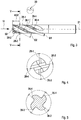
- Reference numeral 20 denotes an end mill which has a cutting section 22 and a clamping shank 24.
- the milling cutter axis is denoted by 21.
- both the cutting section and the clamping shank are cylindrical.
- the cutting section can equally have a different envelope, for example an envelope in the form of a conical jacket.
- the line 26 indicates that the end mill has a so-called neck cut, i.e. the outer diameter of the clamping shank 24 is slightly larger than the nominal diameter of the cutting section 22.
- the cutting section 22 has a plurality of helically extending circumferential cutting edges 26-1 to 26-n, between which flutes 28-1 to 28-n are trained.
- the circumferential cutting edges represent the main cutting edges.
- a number of secondary cutting edges corresponding to the number of circumferential cutting edges is formed, in a conventional manner, so that a more detailed description of this geometry can be omitted here.
- the individual circumferential cutting edges in the embodiment shown are each equipped with a flattened roughing profile 30, which is formed by chip breaker grooves 32 and a flattened section 34 lying in between.
- a flattened roughing profile 30 is formed by chip breaker grooves 32 and a flattened section 34 lying in between.
- the flattened section there can also be a central section which, viewed in the longitudinal section of the milling cutter, follows a preferably slightly convex line.
- the chip splitting grooves 32 extend over the entire width of the milling webs designated by 36-1 to 36-n, in such a way that the chip splitting grooves of milling webs 26-1 and 26-2 or 26-2 and 26-3 or 26-n and 26-1 are axially offset from one another so that the material parts not milled by a peripheral cutting edge can be removed from the next cutting edge.
- the chip thickness doubles, so that, according to the basic machining law of Kienzle and Victor , the specific cutting force is reduced and the torque and power requirement are lower than with tools with a continuous peripheral cutting edge, i.e. with finishing cutters.
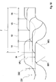
- Fig. 2 is shown schematically on a greatly enlarged scale how the roughing profile 30 can be equipped in detail in the end mill according to the invention.
- the individual chip breaker grooves 32 have a rounded groove base 40 with a smallest radius R40.
- the chip splitting groove 32 merges into the flattened section 34 via a first flank radius RF1.
- the flank radius RF1 is located on the side of the chip breaker groove 32 that faces away from the cutter shank 24.
- the respective chip splitting groove 32 merges into the flattened section 34 of the roughing profile via a second flank radius RF2.
- T the axial distance between adjacent chip breaker grooves 32 of a circumferential cutting edge
- H the depth of the roughing profile 30
- circumferential cutting edges 26-1 to 26-4 are provided, with two circumferential cutting edges 26-1 and 26-3 or 26-2 and 26- lying diametrically opposite each other. 4 each have the same twist angle ⁇ .
- the circumferential cutting edge 26-1 on the milling web 36-1 has, for example, a helix angle ⁇ 1 which differs from the helix angle ⁇ 2 of the adjacent peripheral cutting edge 26-2 by 1 ° to 6 °, preferably by 1 ° to 3 °.
- the helix angle of the peripheral cutting edge 26-1 corresponds exactly to that of the peripheral cutting edge 26-3
- the helix angle of the peripheral cutting edge 26-2 corresponds exactly to that of the peripheral cutting edge 26-4.
- the helix angle ⁇ can vary within wide limits and can, for example, be in the range between 20 ° and over 50 °, depending on the particular machining problem involved.
- the helix angles of diametrically opposed peripheral cutting edges 26-1 and 26-3 or 26-2 and 26-4 are the same but different, namely have the helix angle ⁇ 1 and ⁇ 2, the result on the end face of the end mill - as in FIG Fig. 4 shown - an unequal division.
- the central angle between the adjacent circumferential cutting edges 26-1 and 26-2 or 26-3 and 26-4 is smaller than 90 °, while the other central angle is greater than 90 °.
- the dimension AGT makes up approximately 30% of the length L22 of the cutting section 22.
- Fig. 7 is a perspective view of a field-tested end mill. It can be seen in this figure that the chip breaker grooves 32 are introduced, preferably ground in, in such a way that they are slightly inclined to a plane of the end mill that is perpendicular to the milling cutter axis 21.
- This shaping can be implemented, for example, in that a profiled grinding wheel is used to grind in the chip breaker grooves, which has a profile according to the detail drawing Fig. 2 has, ie an outer contour with the radii R40, RF1 and RF2.
- This grinding wheel can be set at a predetermined angle to the plane of the end mill perpendicular to the milling cutter axis 21, so that the profile grinding wheel can move along a helix whose pitch corresponds to the pitch T of the roughing profile 30 with the chip breaker grooves 32.
- Fig. 8 is schematically indicated the end view of an example of the end mill not belonging to the invention.
- the arrangement is made such that the circumferential cutting edges 126-1 to 126-4 are equally divided on the milling cutter face.
- the plane of section VV in Fig. 3 in this variant lies on the cutter face.
- Fig. 9 a modified embodiment of the end mill is indicated, in which the chip breaker grooves labeled 232 are oriented slightly differently than in the embodiment described above. How out Fig. 9 As can be seen, the chip breaker grooves 232 run parallel to a normal plane to the cutter axis 221.
- the dimension of the chip thickness DS1 is slightly less than the dimension of the following chip thickness DS2 if the circumferential distance of the circumferential cutting edges that come into engagement one after the other is greater than the circumferential distance in front of it.
- the entire end mill consists of hard material, in particular solid hard metal, which results in improved rigidity and an even lower susceptibility to vibrations. With suitable coatings, it is possible to optimize the service life of the end mill.
- the geometry of the roughing profile in particular the ratio of the pitch to the axial length of the flattened section and / or the ratio of the pitch to the depth of the chip breaker groove, is selected as a function of the physical properties of the material to be machined.
- the roughing profile is equipped with a completely flattened central section 34.
- This geometry is not absolutely necessary in order to achieve the advantages according to the invention to a significant extent.
- the central section can also be rounded, preferably slightly bulged or convex, which is shown below with reference to the Figure 11 should be explained in more detail.
- the individual chip breaker grooves 332 have a rounded groove base 340 with a smallest groove radius RN.
- the chip splitting groove 332 merges over a first flank radius RF1 into a slightly convex but still essentially flattened central section 334.
- the flank radius RF1 is located on the side of the chip breaker groove 332 that faces away from the cutter shank.
- the respective chip splitting groove 332 merges into the central section 334 of the roughing profile via a second flank radius RF2.
- the division of the roughing profile i.e. the axial distance between adjacent chip breaker grooves 332 of a circumferential cutting edge is again designated by T, and the depth of the roughing profile 30 by H.
- the contour of the roughing profile can be formed by four circular line segments.
- the section with RF1 is followed by the section with RN, this is followed by the section with RF2 and this is followed by the section with the radius RK, which in the range of the size of the groove radius RN can, however, also be substantially, preferably many times larger than this .
- the central section 334 can also - deviating from a circular line - be formed by another curved curve.
- the convexity K of the profile in the area of the central section 334 is preferably small.
- K LB ⁇ 0.05 .
- the dimension LB denotes the profile length between the flank radii RF1 and RF2.
- the cutting part can be designed with other, conventional cutting edge geometries.
- cutting inserts can also be used.
- the cutting parts can be rectangular, with a corner bevel or with a spherical head.
- the roughing profile in the individual circumferential cutting edges can also be divided unevenly, that is, irregularly over the axial length. It is also possible to change the cross-section of the chip breaker grooves in the circumferential direction.
- a different profile can be formed on the various milling webs. It is also possible to expose individual circumferential cutting edges or diametrical pairs of cutting edges to the circumferential cutting edges.
- a modification can be made such that, with 4 circumferential cutting edges, the cutting edges 1 and 3 are equipped with a roughing profile, while the cutting edges 2 and 4 are smooth-edged.
Landscapes
- Engineering & Computer Science (AREA)
- Mechanical Engineering (AREA)
- Milling Processes (AREA)
- Drilling Tools (AREA)
Applications Claiming Priority (3)
| Application Number | Priority Date | Filing Date | Title |
|---|---|---|---|
| DE102009012012 | 2009-03-07 | ||
| DE102009002738A DE102009002738A1 (de) | 2009-03-07 | 2009-04-29 | Schaftfräser |
| PCT/DE2010/000249 WO2010102605A1 (de) | 2009-03-07 | 2010-03-08 | Schaftfräser |
Publications (3)
| Publication Number | Publication Date |
|---|---|
| EP2403673A1 EP2403673A1 (de) | 2012-01-11 |
| EP2403673B1 EP2403673B1 (de) | 2013-06-19 |
| EP2403673B2 true EP2403673B2 (de) | 2021-12-08 |
Family
ID=42628609
Family Applications (1)
| Application Number | Title | Priority Date | Filing Date |
|---|---|---|---|
| EP10713554.3A Active EP2403673B2 (de) | 2009-03-07 | 2010-03-08 | Schaftfräser |
Country Status (4)
| Country | Link |
|---|---|
| US (3) | US20100226726A1 (hr) |
| EP (1) | EP2403673B2 (hr) |
| DE (1) | DE102009002738A1 (hr) |
| WO (1) | WO2010102605A1 (hr) |
Families Citing this family (34)
| Publication number | Priority date | Publication date | Assignee | Title |
|---|---|---|---|---|
| US8414228B2 (en) * | 2006-01-04 | 2013-04-09 | Sgs Tool Company | Rotary cutting tool |
| EP2436467B1 (en) * | 2009-05-25 | 2022-11-30 | MOLDINO Tool Engineering, Ltd. | Carbide end mill |
| US20110033251A1 (en) * | 2009-08-04 | 2011-02-10 | Kennametal Inc. | Rotary cutting tool with reverse chipbreaker pattern |
| IL203283A (en) * | 2010-01-13 | 2014-02-27 | Iscar Ltd | Cutting put |
| CN103635277B (zh) | 2011-07-05 | 2016-01-13 | Osg株式会社 | 不等导程端铣刀 |
| US10265784B2 (en) * | 2012-10-29 | 2019-04-23 | Kyocera Corporation | Ball end mill |
| DE102013206249A1 (de) * | 2013-04-09 | 2014-10-23 | MAPAL Fabrik für Präzisionswerkzeuge Dr. Kress KG | Fräswerkzeug |
| JP6089917B2 (ja) * | 2013-04-19 | 2017-03-08 | 株式会社不二越 | 不等リードエンドミル |
| DE102013015261A1 (de) | 2013-09-16 | 2015-03-19 | Franz Haimer Maschinenbau Kg | Fräser mit Kordel aus einem speziellen Zahnprofil |
| CN104439466A (zh) * | 2013-09-24 | 2015-03-25 | 上海冠钻精密工具有限公司 | 铣刀 |
| JP6221660B2 (ja) * | 2013-11-12 | 2017-11-01 | 三菱マテリアル株式会社 | ラフィングエンドミル |
| DE102014103103A1 (de) * | 2014-03-07 | 2015-09-10 | Gühring KG | Schaftfräser |
| US20150258616A1 (en) * | 2014-03-11 | 2015-09-17 | Frank J Stanbach | End mill |
| CN104191019A (zh) * | 2014-08-01 | 2014-12-10 | 常州创伟工具制造有限公司 | 双螺旋两刃立铣刀 |
| US10118236B2 (en) * | 2014-09-26 | 2018-11-06 | Kennametal Inc. | Rotary cutting tool |
| JP5958614B2 (ja) * | 2015-07-06 | 2016-08-02 | 三菱マテリアル株式会社 | ボールエンドミル |
| US10052700B2 (en) | 2015-07-28 | 2018-08-21 | Kennametal Inc. | Rotary cutting tool with blades having repeating, unequal indexing and helix angles |
| BE1023432B1 (fr) * | 2016-01-21 | 2017-03-17 | Safran Aero Boosters S.A. | Fraise |
| JP6879668B2 (ja) * | 2016-03-15 | 2021-06-02 | 国立大学法人 名古屋工業大学 | 切削方法 |
| CN105618828A (zh) * | 2016-04-08 | 2016-06-01 | 苏州阿诺精密切削技术股份有限公司 | 一种断齿粗铣刀 |
| DE102016006995B3 (de) * | 2016-06-09 | 2017-10-19 | Hufschmied Zerspanungssysteme Gmbh | Elektrodengrafitfräser |
| CN106238793A (zh) * | 2016-09-19 | 2016-12-21 | 山东大学 | 一种工艺凸台用立铣刀 |
| CN106624097A (zh) * | 2016-12-09 | 2017-05-10 | 海南中智康弘精工技术有限公司 | 一种涡旋波纹刃铣刀 |
| WO2018110697A1 (ja) * | 2016-12-15 | 2018-06-21 | 京セラ株式会社 | 回転工具 |
| CN106735492B (zh) * | 2017-02-15 | 2018-10-26 | 海南中智康弘精工技术有限公司 | 一种铣刀 |
| EP3661683A1 (en) * | 2017-08-03 | 2020-06-10 | Vestas Wind Systems A/S | Mill bit for the manufacture of a wind turbine blade and method of forming same |
| DE102017118943A1 (de) * | 2017-08-18 | 2019-02-21 | Datron Ag | Fräswerkzeug |
| CN107766647B (zh) * | 2017-10-19 | 2020-12-29 | 湖北工业大学 | 一种加工椭圆螺旋转子的成形铣刀廓形数值计算方法 |
| JP7133118B2 (ja) * | 2020-06-22 | 2022-09-07 | 住友電工ハードメタル株式会社 | 切削工具 |
| KR102213944B1 (ko) * | 2020-08-19 | 2021-02-08 | 한상오 | 스펀지 가공용 공구를 이용한 스펀지 가공방법 |
| CN113118531B (zh) * | 2021-04-16 | 2022-06-14 | 江苏科技大学 | 带有断屑槽的粗精加工通用立铣刀 |
| JPWO2022255299A1 (hr) * | 2021-05-31 | 2022-12-08 | ||
| EP4201564A1 (en) * | 2021-12-23 | 2023-06-28 | Walter AG | End mill |
| CN117980100A (zh) * | 2021-12-24 | 2024-05-03 | Osg株式会社 | 立铣刀 |
Citations (6)
| Publication number | Priority date | Publication date | Assignee | Title |
|---|---|---|---|---|
| US4285618A (en) † | 1979-10-12 | 1981-08-25 | Shanley Stephen E Jr | Rotary milling cutter |
| DE3706282A1 (de) † | 1986-02-28 | 1987-09-03 | Izumo Sangyo Kk | Umlaufendes schneidwerkzeug |
| DE29715192U1 (de) † | 1997-08-23 | 1997-12-04 | Schuler Technoplan Gmbh & Co K | Fräswerkzeug |
| US7001113B2 (en) † | 2001-09-10 | 2006-02-21 | Flynn Clifford M | Variable helix cutting tools |
| EP1894655A1 (de) † | 2006-08-28 | 2008-03-05 | Fraisa Holding AG | Fräswerkzeug zum spanenden Bearbeiten von Werkstücken |
| US7367754B1 (en) † | 2006-07-07 | 2008-05-06 | Greenwood Mark L | Variable helix rotary cutting tool |
Family Cites Families (13)
| Publication number | Priority date | Publication date | Assignee | Title |
|---|---|---|---|---|
| US3736634A (en) * | 1971-03-17 | 1973-06-05 | Hicarb Corp | Rotary cutting tool |
| DE7705745U1 (de) * | 1977-02-25 | 1977-06-02 | Hawera Probst Gmbh + Co, 7980 Ravensburg | Fraeser, insbesondere konturenfraeser |
| DE8110928U1 (de) * | 1981-04-10 | 1981-12-03 | BIAX-Werkzeuge KG, Wezel & Co, Präzisionswerkzeugfabrik, 7133 Maulbronn | Fraeswerkzeug |
| US4770567A (en) * | 1983-06-20 | 1988-09-13 | Colt Industries Operating Corp. | Roughing cutter |
| US4810136A (en) * | 1983-11-09 | 1989-03-07 | The Boeing Company | Milling cutter for composite laminates |
| FR2875722A1 (fr) * | 2004-09-27 | 2006-03-31 | Alsameca Sa | Fraise de coupe |
| JP4553251B2 (ja) * | 2005-04-13 | 2010-09-29 | オーエスジー株式会社 | ねじ切りカッタ |
| US7399147B1 (en) * | 2005-08-09 | 2008-07-15 | Vandyke Jr Daryl C | End mill bit with notched teeth |
| IL177336A (en) * | 2006-08-07 | 2013-05-30 | Hanita Metal Works Ltd | Anti-vibration stabilized finger milling |
| DE202006016531U1 (de) * | 2006-10-28 | 2007-07-19 | Hofmann & Vratny Ohg | Schlicht-/Schruppfräser |
| DE102007021562B4 (de) | 2007-05-08 | 2012-05-03 | Kmp Printtechnik Ag | Tintenpatrone |
| JPWO2009122937A1 (ja) * | 2008-03-31 | 2011-07-28 | 住友電工ハードメタル株式会社 | エンドミル |
| DE102008018399A1 (de) * | 2008-04-10 | 2009-10-15 | Sandvik Intellectual Property Ab | Schaftfräser mit unterschiedlichen Drallwinkeln |
-
2009
- 2009-04-29 DE DE102009002738A patent/DE102009002738A1/de not_active Withdrawn
- 2009-07-31 US US12/533,269 patent/US20100226726A1/en not_active Abandoned
-
2010
- 2010-03-08 EP EP10713554.3A patent/EP2403673B2/de active Active
- 2010-03-08 WO PCT/DE2010/000249 patent/WO2010102605A1/de active Application Filing
-
2012
- 2012-09-27 US US13/628,370 patent/US20130022416A1/en not_active Abandoned
-
2015
- 2015-01-27 US US14/606,186 patent/US9352400B2/en active Active
Patent Citations (6)
| Publication number | Priority date | Publication date | Assignee | Title |
|---|---|---|---|---|
| US4285618A (en) † | 1979-10-12 | 1981-08-25 | Shanley Stephen E Jr | Rotary milling cutter |
| DE3706282A1 (de) † | 1986-02-28 | 1987-09-03 | Izumo Sangyo Kk | Umlaufendes schneidwerkzeug |
| DE29715192U1 (de) † | 1997-08-23 | 1997-12-04 | Schuler Technoplan Gmbh & Co K | Fräswerkzeug |
| US7001113B2 (en) † | 2001-09-10 | 2006-02-21 | Flynn Clifford M | Variable helix cutting tools |
| US7367754B1 (en) † | 2006-07-07 | 2008-05-06 | Greenwood Mark L | Variable helix rotary cutting tool |
| EP1894655A1 (de) † | 2006-08-28 | 2008-03-05 | Fraisa Holding AG | Fräswerkzeug zum spanenden Bearbeiten von Werkstücken |
Non-Patent Citations (3)
| Title |
|---|
| Informationsblatt der Fa. Hommel Hercules zu Fräsertypen, DIN 1836, Januar 1984 † |
| Produktkatalog 03/2007, Fa. Rübig † |
| Produktkatalog 2009, Fa. Dormer † |
Also Published As
| Publication number | Publication date |
|---|---|
| US20130022416A1 (en) | 2013-01-24 |
| US9352400B2 (en) | 2016-05-31 |
| WO2010102605A1 (de) | 2010-09-16 |
| DE102009002738A1 (de) | 2010-09-23 |
| US20150158095A1 (en) | 2015-06-11 |
| US20100226726A1 (en) | 2010-09-09 |
| EP2403673B1 (de) | 2013-06-19 |
| EP2403673A1 (de) | 2012-01-11 |
Similar Documents
| Publication | Publication Date | Title |
|---|---|---|
| EP2403673B2 (de) | Schaftfräser | |
| DE102005002698B4 (de) | Fräswerkzeug | |
| EP1864737B1 (de) | Spanabhebendes Werkzeug | |
| EP1907158B1 (de) | Schneideinsatz, werkzeug sowie verfahren zur spanenden bearbeitung eines werkstücks | |
| EP2323792B1 (de) | Mehrschneidiges bohrwerkzeug | |
| EP3150313B1 (de) | Vollfräswerkzeug zur rotierenden materialbearbeitung | |
| DE102005038021B4 (de) | Verfahren zur zerspanenden Bearbeitung von Kurbelwellen und Vorrichtung zur Durchführung dieses Verfahrens | |
| EP1511590B1 (de) | Fräser mit wiper-radius | |
| DE102015112417B4 (de) | Rotierendes Schneidwerkzeug mit nachschleifbaren Schneideinsätzen | |
| EP0937528A1 (de) | Reibwerkzeug und Verfahren zu dessen Herstellung | |
| DE3831535A1 (de) | Stirnfraeser | |
| DE102016206721A1 (de) | Schneidwerkzeug zur verbesserten Spanabfuhr und Verfahren zu dessen Herstellung | |
| WO2016020047A1 (de) | Fräswerkzeug | |
| DE112011102667T5 (de) | Konturschaftfräser | |
| EP3356071B1 (de) | Schlichtfräswerkzeug, insbesondere schaftfräser | |
| DE112017000520B4 (de) | Schaftfräser und Verfahren des Herstellens eines maschinell-bearbeiteten Produkts | |
| EP2929966B1 (de) | Vollfräswerkzeug zur rotierenden Materialbearbeitung | |
| WO2008052503A1 (de) | Schlicht- /schruppfräser | |
| DE202004007624U1 (de) | Stabmesser zum Fräsen von Spiralkegel- und Hypoidrädern | |
| DE102004022360B4 (de) | Verfahren zur Feinbearbeitung, vorzugsweise zur Feinstschlichtbearbeitung, von Werkstücken vorzugsweise von Kurbelwellen | |
| EP0485546B1 (de) | Schneideinsatz für werkzeuge | |
| DE102005058536B4 (de) | Schneidwerkzeugsystem, insbesondere zum Verzahnen von Kegelrädern im Einzel-Teil-Verfahren | |
| DE19626608B4 (de) | Verfahren zur spanenden Bearbeitung | |
| WO2018219926A1 (de) | Einlippen-tieflochbohrer mit abgesetzter spanfläche | |
| EP2420337B1 (de) | Verwendung einer Wendeplatte zum Fasen, und Zusammenstellung eines konischen oder zylindrischen Fräskopfs und einer Wendeplatte zum Fasen |
Legal Events
| Date | Code | Title | Description |
|---|---|---|---|
| PUAI | Public reference made under article 153(3) epc to a published international application that has entered the european phase |
Free format text: ORIGINAL CODE: 0009012 |
|
| 17P | Request for examination filed |
Effective date: 20110929 |
|
| AK | Designated contracting states |
Kind code of ref document: A1 Designated state(s): AT BE BG CH CY CZ DE DK EE ES FI FR GB GR HR HU IE IS IT LI LT LU LV MC MK MT NL NO PL PT RO SE SI SK SM TR |
|
| DAX | Request for extension of the european patent (deleted) | ||
| GRAP | Despatch of communication of intention to grant a patent |
Free format text: ORIGINAL CODE: EPIDOSNIGR1 |
|
| GRAJ | Information related to disapproval of communication of intention to grant by the applicant or resumption of examination proceedings by the epo deleted |
Free format text: ORIGINAL CODE: EPIDOSDIGR1 |
|
| GRAP | Despatch of communication of intention to grant a patent |
Free format text: ORIGINAL CODE: EPIDOSNIGR1 |
|
| GRAC | Information related to communication of intention to grant a patent modified |
Free format text: ORIGINAL CODE: EPIDOSCIGR1 |
|
| GRAP | Despatch of communication of intention to grant a patent |
Free format text: ORIGINAL CODE: EPIDOSNIGR1 |
|
| GRAS | Grant fee paid |
Free format text: ORIGINAL CODE: EPIDOSNIGR3 |
|
| GRAA | (expected) grant |
Free format text: ORIGINAL CODE: 0009210 |
|
| STAA | Information on the status of an ep patent application or granted ep patent |
Free format text: STATUS: THE PATENT HAS BEEN GRANTED |
|
| AK | Designated contracting states |
Kind code of ref document: B1 Designated state(s): AT BE BG CH CY CZ DE DK EE ES FI FR GB GR HR HU IE IS IT LI LT LU LV MC MK MT NL NO PL PT RO SE SI SK SM TR |
|
| REG | Reference to a national code |
Ref country code: GB Ref legal event code: FG4D Free format text: NOT ENGLISH |
|
| REG | Reference to a national code |
Ref country code: CH Ref legal event code: EP |
|
| REG | Reference to a national code |
Ref country code: AT Ref legal event code: REF Ref document number: 617355 Country of ref document: AT Kind code of ref document: T Effective date: 20130715 |
|
| REG | Reference to a national code |
Ref country code: IE Ref legal event code: FG4D Free format text: LANGUAGE OF EP DOCUMENT: GERMAN |
|
| REG | Reference to a national code |
Ref country code: DE Ref legal event code: R096 Ref document number: 502010003727 Country of ref document: DE Effective date: 20130814 |
|
| PG25 | Lapsed in a contracting state [announced via postgrant information from national office to epo] |
Ref country code: ES Free format text: LAPSE BECAUSE OF FAILURE TO SUBMIT A TRANSLATION OF THE DESCRIPTION OR TO PAY THE FEE WITHIN THE PRESCRIBED TIME-LIMIT Effective date: 20130930 Ref country code: NO Free format text: LAPSE BECAUSE OF FAILURE TO SUBMIT A TRANSLATION OF THE DESCRIPTION OR TO PAY THE FEE WITHIN THE PRESCRIBED TIME-LIMIT Effective date: 20130919 Ref country code: GR Free format text: LAPSE BECAUSE OF FAILURE TO SUBMIT A TRANSLATION OF THE DESCRIPTION OR TO PAY THE FEE WITHIN THE PRESCRIBED TIME-LIMIT Effective date: 20130920 Ref country code: SI Free format text: LAPSE BECAUSE OF FAILURE TO SUBMIT A TRANSLATION OF THE DESCRIPTION OR TO PAY THE FEE WITHIN THE PRESCRIBED TIME-LIMIT Effective date: 20130619 Ref country code: SE Free format text: LAPSE BECAUSE OF FAILURE TO SUBMIT A TRANSLATION OF THE DESCRIPTION OR TO PAY THE FEE WITHIN THE PRESCRIBED TIME-LIMIT Effective date: 20130619 Ref country code: LT Free format text: LAPSE BECAUSE OF FAILURE TO SUBMIT A TRANSLATION OF THE DESCRIPTION OR TO PAY THE FEE WITHIN THE PRESCRIBED TIME-LIMIT Effective date: 20130619 Ref country code: FI Free format text: LAPSE BECAUSE OF FAILURE TO SUBMIT A TRANSLATION OF THE DESCRIPTION OR TO PAY THE FEE WITHIN THE PRESCRIBED TIME-LIMIT Effective date: 20130619 |
|
| REG | Reference to a national code |
Ref country code: LT Ref legal event code: MG4D |
|
| PG25 | Lapsed in a contracting state [announced via postgrant information from national office to epo] |
Ref country code: BG Free format text: LAPSE BECAUSE OF FAILURE TO SUBMIT A TRANSLATION OF THE DESCRIPTION OR TO PAY THE FEE WITHIN THE PRESCRIBED TIME-LIMIT Effective date: 20130919 Ref country code: HR Free format text: LAPSE BECAUSE OF FAILURE TO SUBMIT A TRANSLATION OF THE DESCRIPTION OR TO PAY THE FEE WITHIN THE PRESCRIBED TIME-LIMIT Effective date: 20130619 |
|
| REG | Reference to a national code |
Ref country code: NL Ref legal event code: VDEP Effective date: 20130619 |
|
| PG25 | Lapsed in a contracting state [announced via postgrant information from national office to epo] |
Ref country code: LV Free format text: LAPSE BECAUSE OF FAILURE TO SUBMIT A TRANSLATION OF THE DESCRIPTION OR TO PAY THE FEE WITHIN THE PRESCRIBED TIME-LIMIT Effective date: 20130619 |
|
| PG25 | Lapsed in a contracting state [announced via postgrant information from national office to epo] |
Ref country code: EE Free format text: LAPSE BECAUSE OF FAILURE TO SUBMIT A TRANSLATION OF THE DESCRIPTION OR TO PAY THE FEE WITHIN THE PRESCRIBED TIME-LIMIT Effective date: 20130619 Ref country code: SK Free format text: LAPSE BECAUSE OF FAILURE TO SUBMIT A TRANSLATION OF THE DESCRIPTION OR TO PAY THE FEE WITHIN THE PRESCRIBED TIME-LIMIT Effective date: 20130619 Ref country code: CY Free format text: LAPSE BECAUSE OF FAILURE TO SUBMIT A TRANSLATION OF THE DESCRIPTION OR TO PAY THE FEE WITHIN THE PRESCRIBED TIME-LIMIT Effective date: 20130807 Ref country code: CZ Free format text: LAPSE BECAUSE OF FAILURE TO SUBMIT A TRANSLATION OF THE DESCRIPTION OR TO PAY THE FEE WITHIN THE PRESCRIBED TIME-LIMIT Effective date: 20130619 Ref country code: IS Free format text: LAPSE BECAUSE OF FAILURE TO SUBMIT A TRANSLATION OF THE DESCRIPTION OR TO PAY THE FEE WITHIN THE PRESCRIBED TIME-LIMIT Effective date: 20131019 Ref country code: PT Free format text: LAPSE BECAUSE OF FAILURE TO SUBMIT A TRANSLATION OF THE DESCRIPTION OR TO PAY THE FEE WITHIN THE PRESCRIBED TIME-LIMIT Effective date: 20131021 |
|
| REG | Reference to a national code |
Ref country code: DE Ref legal event code: R082 Ref document number: 502010003727 Country of ref document: DE Representative=s name: WINTER, BRANDL, FUERNISS, HUEBNER, ROESS, KAIS, DE |
|
| PG25 | Lapsed in a contracting state [announced via postgrant information from national office to epo] |
Ref country code: PL Free format text: LAPSE BECAUSE OF FAILURE TO SUBMIT A TRANSLATION OF THE DESCRIPTION OR TO PAY THE FEE WITHIN THE PRESCRIBED TIME-LIMIT Effective date: 20130619 Ref country code: RO Free format text: LAPSE BECAUSE OF FAILURE TO SUBMIT A TRANSLATION OF THE DESCRIPTION OR TO PAY THE FEE WITHIN THE PRESCRIBED TIME-LIMIT Effective date: 20130619 Ref country code: NL Free format text: LAPSE BECAUSE OF FAILURE TO SUBMIT A TRANSLATION OF THE DESCRIPTION OR TO PAY THE FEE WITHIN THE PRESCRIBED TIME-LIMIT Effective date: 20130619 |
|
| REG | Reference to a national code |
Ref country code: DE Ref legal event code: R081 Ref document number: 502010003727 Country of ref document: DE Owner name: GUEHRING KG, DE Free format text: FORMER OWNER: GUEHRING OHG, 72458 ALBSTADT, DE Effective date: 20140203 Ref country code: DE Ref legal event code: R082 Ref document number: 502010003727 Country of ref document: DE Representative=s name: WINTER, BRANDL, FUERNISS, HUEBNER, ROESS, KAIS, DE Effective date: 20140203 |
|
| PLBI | Opposition filed |
Free format text: ORIGINAL CODE: 0009260 |
|
| PG25 | Lapsed in a contracting state [announced via postgrant information from national office to epo] |
Ref country code: CY Free format text: LAPSE BECAUSE OF FAILURE TO SUBMIT A TRANSLATION OF THE DESCRIPTION OR TO PAY THE FEE WITHIN THE PRESCRIBED TIME-LIMIT Effective date: 20130619 |
|
| PLAX | Notice of opposition and request to file observation + time limit sent |
Free format text: ORIGINAL CODE: EPIDOSNOBS2 |
|
| 26 | Opposition filed |
Opponent name: HAIMER GMBH Effective date: 20140319 |
|
| PG25 | Lapsed in a contracting state [announced via postgrant information from national office to epo] |
Ref country code: DK Free format text: LAPSE BECAUSE OF FAILURE TO SUBMIT A TRANSLATION OF THE DESCRIPTION OR TO PAY THE FEE WITHIN THE PRESCRIBED TIME-LIMIT Effective date: 20130619 |
|
| PG25 | Lapsed in a contracting state [announced via postgrant information from national office to epo] |
Ref country code: IT Free format text: LAPSE BECAUSE OF FAILURE TO SUBMIT A TRANSLATION OF THE DESCRIPTION OR TO PAY THE FEE WITHIN THE PRESCRIBED TIME-LIMIT Effective date: 20130619 |
|
| REG | Reference to a national code |
Ref country code: DE Ref legal event code: R026 Ref document number: 502010003727 Country of ref document: DE Effective date: 20140319 |
|
| PLAF | Information modified related to communication of a notice of opposition and request to file observations + time limit |
Free format text: ORIGINAL CODE: EPIDOSCOBS2 |
|
| PG25 | Lapsed in a contracting state [announced via postgrant information from national office to epo] |
Ref country code: LU Free format text: LAPSE BECAUSE OF FAILURE TO SUBMIT A TRANSLATION OF THE DESCRIPTION OR TO PAY THE FEE WITHIN THE PRESCRIBED TIME-LIMIT Effective date: 20140308 |
|
| REG | Reference to a national code |
Ref country code: CH Ref legal event code: PL |
|
| PLBB | Reply of patent proprietor to notice(s) of opposition received |
Free format text: ORIGINAL CODE: EPIDOSNOBS3 |
|
| GBPC | Gb: european patent ceased through non-payment of renewal fee |
Effective date: 20140308 |
|
| REG | Reference to a national code |
Ref country code: FR Ref legal event code: ST Effective date: 20141128 |
|
| REG | Reference to a national code |
Ref country code: IE Ref legal event code: MM4A |
|
| PG25 | Lapsed in a contracting state [announced via postgrant information from national office to epo] |
Ref country code: FR Free format text: LAPSE BECAUSE OF NON-PAYMENT OF DUE FEES Effective date: 20140331 Ref country code: CH Free format text: LAPSE BECAUSE OF NON-PAYMENT OF DUE FEES Effective date: 20140331 Ref country code: GB Free format text: LAPSE BECAUSE OF NON-PAYMENT OF DUE FEES Effective date: 20140308 Ref country code: LI Free format text: LAPSE BECAUSE OF NON-PAYMENT OF DUE FEES Effective date: 20140331 Ref country code: IE Free format text: LAPSE BECAUSE OF NON-PAYMENT OF DUE FEES Effective date: 20140308 |
|
| TPAC | Observations filed by third parties |
Free format text: ORIGINAL CODE: EPIDOSNTIPA |
|
| TPAB | Information related to observations by third parties deleted |
Free format text: ORIGINAL CODE: EPIDOSDTIPA |
|
| PG25 | Lapsed in a contracting state [announced via postgrant information from national office to epo] |
Ref country code: MT Free format text: LAPSE BECAUSE OF FAILURE TO SUBMIT A TRANSLATION OF THE DESCRIPTION OR TO PAY THE FEE WITHIN THE PRESCRIBED TIME-LIMIT Effective date: 20130619 |
|
| PG25 | Lapsed in a contracting state [announced via postgrant information from national office to epo] |
Ref country code: SM Free format text: LAPSE BECAUSE OF FAILURE TO SUBMIT A TRANSLATION OF THE DESCRIPTION OR TO PAY THE FEE WITHIN THE PRESCRIBED TIME-LIMIT Effective date: 20130619 |
|
| RDAF | Communication despatched that patent is revoked |
Free format text: ORIGINAL CODE: EPIDOSNREV1 |
|
| REG | Reference to a national code |
Ref country code: AT Ref legal event code: MM01 Ref document number: 617355 Country of ref document: AT Kind code of ref document: T Effective date: 20150308 |
|
| PG25 | Lapsed in a contracting state [announced via postgrant information from national office to epo] |
Ref country code: MC Free format text: LAPSE BECAUSE OF FAILURE TO SUBMIT A TRANSLATION OF THE DESCRIPTION OR TO PAY THE FEE WITHIN THE PRESCRIBED TIME-LIMIT Effective date: 20130619 |
|
| APBM | Appeal reference recorded |
Free format text: ORIGINAL CODE: EPIDOSNREFNO |
|
| APBP | Date of receipt of notice of appeal recorded |
Free format text: ORIGINAL CODE: EPIDOSNNOA2O |
|
| APAH | Appeal reference modified |
Free format text: ORIGINAL CODE: EPIDOSCREFNO |
|
| PG25 | Lapsed in a contracting state [announced via postgrant information from national office to epo] |
Ref country code: HU Free format text: LAPSE BECAUSE OF FAILURE TO SUBMIT A TRANSLATION OF THE DESCRIPTION OR TO PAY THE FEE WITHIN THE PRESCRIBED TIME-LIMIT; INVALID AB INITIO Effective date: 20100308 Ref country code: BE Free format text: LAPSE BECAUSE OF FAILURE TO SUBMIT A TRANSLATION OF THE DESCRIPTION OR TO PAY THE FEE WITHIN THE PRESCRIBED TIME-LIMIT Effective date: 20140331 Ref country code: TR Free format text: LAPSE BECAUSE OF FAILURE TO SUBMIT A TRANSLATION OF THE DESCRIPTION OR TO PAY THE FEE WITHIN THE PRESCRIBED TIME-LIMIT Effective date: 20130619 |
|
| RAP2 | Party data changed (patent owner data changed or rights of a patent transferred) |
Owner name: GUEHRING KG |
|
| PG25 | Lapsed in a contracting state [announced via postgrant information from national office to epo] |
Ref country code: AT Free format text: LAPSE BECAUSE OF NON-PAYMENT OF DUE FEES Effective date: 20150308 |
|
| APBQ | Date of receipt of statement of grounds of appeal recorded |
Free format text: ORIGINAL CODE: EPIDOSNNOA3O |
|
| PG25 | Lapsed in a contracting state [announced via postgrant information from national office to epo] |
Ref country code: MK Free format text: LAPSE BECAUSE OF FAILURE TO SUBMIT A TRANSLATION OF THE DESCRIPTION OR TO PAY THE FEE WITHIN THE PRESCRIBED TIME-LIMIT Effective date: 20130619 |
|
| APAH | Appeal reference modified |
Free format text: ORIGINAL CODE: EPIDOSCREFNO |
|
| APBU | Appeal procedure closed |
Free format text: ORIGINAL CODE: EPIDOSNNOA9O |
|
| PUAH | Patent maintained in amended form |
Free format text: ORIGINAL CODE: 0009272 |
|
| STAA | Information on the status of an ep patent application or granted ep patent |
Free format text: STATUS: PATENT MAINTAINED AS AMENDED |
|
| 27A | Patent maintained in amended form |
Effective date: 20211208 |
|
| AK | Designated contracting states |
Kind code of ref document: B2 Designated state(s): AT BE BG CH CY CZ DE DK EE ES FI FR GB GR HR HU IE IS IT LI LT LU LV MC MK MT NL NO PL PT RO SE SI SK SM TR |
|
| REG | Reference to a national code |
Ref country code: DE Ref legal event code: R102 Ref document number: 502010003727 Country of ref document: DE |
|
| PGFP | Annual fee paid to national office [announced via postgrant information from national office to epo] |
Ref country code: DE Payment date: 20240331 Year of fee payment: 15 |