EP2401552B1 - Verfahren zur selbstgängigen verbrennung von schlamm - Google Patents
Verfahren zur selbstgängigen verbrennung von schlamm Download PDFInfo
- Publication number
- EP2401552B1 EP2401552B1 EP10706501A EP10706501A EP2401552B1 EP 2401552 B1 EP2401552 B1 EP 2401552B1 EP 10706501 A EP10706501 A EP 10706501A EP 10706501 A EP10706501 A EP 10706501A EP 2401552 B1 EP2401552 B1 EP 2401552B1
- Authority
- EP
- European Patent Office
- Prior art keywords
- heat exchanger
- sludge
- slurry
- combustion
- flue gas
- Prior art date
- Legal status (The legal status is an assumption and is not a legal conclusion. Google has not performed a legal analysis and makes no representation as to the accuracy of the status listed.)
- Not-in-force
Links
- 238000002485 combustion reaction Methods 0.000 title claims description 61
- 238000000034 method Methods 0.000 title claims description 28
- 239000010802 sludge Substances 0.000 title description 65
- 230000002358 autolytic effect Effects 0.000 title 1
- 239000003546 flue gas Substances 0.000 claims description 52
- UGFAIRIUMAVXCW-UHFFFAOYSA-N Carbon monoxide Chemical compound [O+]#[C-] UGFAIRIUMAVXCW-UHFFFAOYSA-N 0.000 claims description 51
- 239000010801 sewage sludge Substances 0.000 claims description 40
- 238000010438 heat treatment Methods 0.000 claims description 23
- XLYOFNOQVPJJNP-UHFFFAOYSA-N water Substances O XLYOFNOQVPJJNP-UHFFFAOYSA-N 0.000 claims description 17
- 239000007787 solid Substances 0.000 claims description 9
- 239000007791 liquid phase Substances 0.000 claims description 5
- 239000002002 slurry Substances 0.000 claims 12
- 238000011144 upstream manufacturing Methods 0.000 claims 1
- 238000010586 diagram Methods 0.000 description 11
- 239000003292 glue Substances 0.000 description 7
- 239000012071 phase Substances 0.000 description 7
- 239000007789 gas Substances 0.000 description 6
- 239000000203 mixture Substances 0.000 description 5
- OKTJSMMVPCPJKN-UHFFFAOYSA-N Carbon Chemical compound [C] OKTJSMMVPCPJKN-UHFFFAOYSA-N 0.000 description 4
- 206010053615 Thermal burn Diseases 0.000 description 3
- 238000001035 drying Methods 0.000 description 3
- 239000000470 constituent Substances 0.000 description 2
- 238000010276 construction Methods 0.000 description 2
- 230000007423 decrease Effects 0.000 description 2
- 239000002910 solid waste Substances 0.000 description 2
- 230000002269 spontaneous effect Effects 0.000 description 2
- 230000015572 biosynthetic process Effects 0.000 description 1
- 229910052799 carbon Inorganic materials 0.000 description 1
- 230000003247 decreasing effect Effects 0.000 description 1
- 230000018044 dehydration Effects 0.000 description 1
- 238000006297 dehydration reaction Methods 0.000 description 1
- 238000011161 development Methods 0.000 description 1
- 230000018109 developmental process Effects 0.000 description 1
- 238000001704 evaporation Methods 0.000 description 1
- 238000007654 immersion Methods 0.000 description 1
- 239000007788 liquid Substances 0.000 description 1
- 239000010813 municipal solid waste Substances 0.000 description 1
- 235000019645 odor Nutrition 0.000 description 1
- 230000003647 oxidation Effects 0.000 description 1
- 238000007254 oxidation reaction Methods 0.000 description 1
- 230000000704 physical effect Effects 0.000 description 1
- 229920000642 polymer Polymers 0.000 description 1
- 102000004169 proteins and genes Human genes 0.000 description 1
- 108090000623 proteins and genes Proteins 0.000 description 1
- 238000004064 recycling Methods 0.000 description 1
- 238000000926 separation method Methods 0.000 description 1
- 239000002699 waste material Substances 0.000 description 1
Images

Classifications
-
- F—MECHANICAL ENGINEERING; LIGHTING; HEATING; WEAPONS; BLASTING
- F23—COMBUSTION APPARATUS; COMBUSTION PROCESSES
- F23G—CREMATION FURNACES; CONSUMING WASTE PRODUCTS BY COMBUSTION
- F23G7/00—Incinerators or other apparatus for consuming industrial waste, e.g. chemicals
- F23G7/001—Incinerators or other apparatus for consuming industrial waste, e.g. chemicals for sludges or waste products from water treatment installations
-
- F—MECHANICAL ENGINEERING; LIGHTING; HEATING; WEAPONS; BLASTING
- F23—COMBUSTION APPARATUS; COMBUSTION PROCESSES
- F23G—CREMATION FURNACES; CONSUMING WASTE PRODUCTS BY COMBUSTION
- F23G2206/00—Waste heat recuperation
- F23G2206/10—Waste heat recuperation reintroducing the heat in the same process, e.g. for predrying
-
- F—MECHANICAL ENGINEERING; LIGHTING; HEATING; WEAPONS; BLASTING
- F23—COMBUSTION APPARATUS; COMBUSTION PROCESSES
- F23G—CREMATION FURNACES; CONSUMING WASTE PRODUCTS BY COMBUSTION
- F23G2209/00—Specific waste
- F23G2209/12—Sludge, slurries or mixtures of liquids
-
- F—MECHANICAL ENGINEERING; LIGHTING; HEATING; WEAPONS; BLASTING
- F23—COMBUSTION APPARATUS; COMBUSTION PROCESSES
- F23G—CREMATION FURNACES; CONSUMING WASTE PRODUCTS BY COMBUSTION
- F23G2900/00—Special features of, or arrangements for incinerators
- F23G2900/00001—Exhaust gas recirculation
-
- F—MECHANICAL ENGINEERING; LIGHTING; HEATING; WEAPONS; BLASTING
- F23—COMBUSTION APPARATUS; COMBUSTION PROCESSES
- F23G—CREMATION FURNACES; CONSUMING WASTE PRODUCTS BY COMBUSTION
- F23G2900/00—Special features of, or arrangements for incinerators
- F23G2900/50213—Preheating processes other than drying or pyrolysis
Definitions
- the invention relates to a method for the automatic combustion of sludge.
- sludges for their disposal are self-contained, that burned without external thermal energy.
- Such sludges can be formed in particular by sewage sludge.
- the mechanically dewatered sludge is fed to a dryer, for example a drum, disc or stacker dryer, by methods known in the art.
- the sludge dried there is then fed to a combustion unit, for example a fluidized bed furnace, where it is incinerated.
- the running of the combustion unit, hot flue gas is used in these methods as a heating medium in the dryer.
- a major disadvantage here is that the design effort and thus the cost of implementing the method is undesirably large.
- a further disadvantage is that during drying of the sludge in the dryer, in particular when the sludge is sewage sludge, exhaust gases with organic constituents are formed which have to be filtered out with an exhaust system such as activated carbon filters. This represents another significant cost factor.
- sewage sludge but also other protein-containing sludges change their physical properties at a solids content of about 30-70% in the way that they go through the so-called glue phase.
- the viscosity of the sludge increases significantly and there are problems in conveying the sludge.
- the sludge is heated to a temperature of, for example, greater than 180 ° C, the long-chain molecules contained in the sludge break up and the sludge hydrolyzes, and thus no glue phase is produced when the dry matter increases and the sludge has a much lower viscosity.
- the DE 31 03 417 A1 relates to a process for the oxidation of solids and aqueous sludges, in particular solid waste such as waste and sewage sludge in an oven.
- aqueous sludges, especially sewage sludge in a predetermined amount with solids, especially crushed combustible solid waste (garbage), mixed intensively, fed without dewatering in the oven and burned under pressure, strigwelt or gasified.
- the EP 0 304 783 A1 relates to a process for burning aqueous sewage sludge in fluidized bed, wherein aqueous mixtures of sewage sludge and TDI residues having a solids content of 25 to 98 wt .-% and their content of TDI residue 25 to 95 wt .-%, based on The solids content is burned without further input of energy carrier.
- the invention has for its object to provide a method of the type mentioned, by means of which a cost-effective and efficient combustion of sludge is made possible without additional thermal energy supply.
- the inventive method is used for the automatic combustion of sludge with a high water content.
- the sludge is heated under pressure before being fed to a combustion unit in a heat exchanger, so that the water contained in the sludge does not evaporate but remains in a liquid phase.
- the sludge to be incinerated has a high water content because prior mechanical dehydration typically can not lower the water content of the sludge to below about 75%.
- the feed of this hydrous sludge to the incineration unit takes place in conduits through which the sludge is pumped at high pressures, typically at least 40 bar. In these lines, the sludge is heated by means of the heat exchanger. Due to the high pressure, the sludge can absorb large amounts of heat without the water evaporating in the sludge. The sludge water thus remains in the liquid phase and the sludge thus remains pumpable.
- the sludge When the sludge is heated under pressure, it hydrolyzes, ie large organic molecules are broken up and the viscosity of the sludge decreases considerably. This is an essential prerequisite for a controlled supply of sludge to the combustion unit and a compact design of the system components. There, the pre-heated sludge can be burned energy-efficient.
- the pumpability of the sludge to be supplied to the heat exchanger is considerably improved by recycling a portion of the sludge heated in the heat exchanger and mixing it with fresh sludge forming sludge before being fed to the heat exchanger under pressure.
- the temperature of the raw sludge mixed with the recycled sludge is increased so that in this case the formation of a glue phase in the heat exchanger
- Shape of a tough mud avoided or at least partially reduced.
- this raw sludge is preheated before entering the heat exchanger.
- the raw sludge is heated to such an extent by the mixture with sludge already passed through the heat exchanger that the mixture thus obtained is at such a high temperature that it no longer passes through any glue phase in the heat exchanger.
- the mixture is made so that it passes through the glue phase only very short and incomplete in the heat exchanger. In any case, achieved by the sludge recirculation avoidance of the glue phase is achieved, that the sludge remains well pumpable when passing through the heat exchanger and thus can pass well this.
- Essential for an automatic combustion of the sludge without external thermal energy supply in this case is that the heat exchanger for heating the sludge, the flue gas is supplied as a heat exchange medium.
- the heat exchanger for heating the sludge is designed as a thermal oil heat exchanger, wherein the thermal oil is heated by means of the flue gas.
- a heat exchanger with high-pressure steam or high-pressure hot water can be used as a heat exchange medium.
- thermal oil as a heat carrier between the flue gas and the sludge is an alternative embodiment of the method. It is particularly advantageous, however, that the heat exchanger for heating the Sludge the flue gas is supplied as a heat exchange medium. Coils are expediently installed for heating the sludge under pressure in the flue gas duct behind a fluidized bed combustion as a combustion unit. This could also be realized by immersion heating surfaces built into the fluidized-bed combustion or by radiant heating surfaces in the combustion chamber.
- This method has as an additional advantage that the sludge can be heated directly by the exhaust gas stream, so that it is possible to dispense with thermal oil heat exchangers or a corresponding unit.
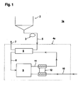
- FIG. 1 shows schematically the structure of a known from the prior art plant 1a for the spontaneous combustion of sludge.
- sewage sludge is always mentioned as an example of a sludge to be disposed of.
- the sewage sludge is first supplied from a reservoir 2 of a mechanical drainage 3, which is formed by a press or the like. There, the water content of sewage sludge is reduced by mechanical means to about 75%. From the mechanical dewatering the sewage sludge is fed to a system 4a for self-combustion to burn the sewage sludge without additional thermal energy supply.
- the sewage sludge is first fed via a line 5 to a dryer 6, which is typically designed as a tube dryer. In the dryer 6, the sewage sludge is dried. In order to filter the resulting exhaust gases, the dryer 6 is associated with a filter system, not shown, such as an activated carbon filter.
- the exhaust air of the dryer 6 is discharged from the system 4a via a line 7.
- the sewage sludge dried in the drier 6 is fed via a line 8 to a combustion unit, which is formed, for example, by a fluidized-bed furnace 9.
- the combustion unit is supplied via a line 10 combustion air.
- the resulting in the fluidized bed combustion 9 hot flue gas is carried out via a line 11 from the fluidized bed furnace 9 and fed to the dryer 6 as a heating medium.
- the combustion air is heated by using the heat of the noise gas.
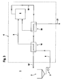
- the Figures 2 and 3 show embodiments of the system 1 according to the invention for the spontaneous combustion of sludge, which is again exemplified as sewage sludge.
- the sewage sludge is supplied from a reservoir 2 to a mechanical drainage 3 such as a press. There, the mechanical content of the water content sewage sludge is reduced to about 75%.
- the sewage sludge is fed to a system 4 for automatic combustion.
- the sewage sludge Due to the high pressure prevailing in the line 5, the sewage sludge remains liquid when heated and can thus be supplied with compact plant components, in particular lines 5 of the combustion unit.
- the emerging from the combustion unit hot flue gases are used to heat the sewage sludge, whereby a closed system 4 is obtained without external thermal energy supply.
- the sludge is fed in the line 5 a combustion unit in the form of a fluidized bed 9.
- the combustion unit (as in the following embodiment according to FIG. 3 ) be formed by a cyclone furnace or a rotary kiln.
- the sewage sludge in the line 5 is heated by means of a heat exchanger system in the form of a thermal oil heat exchanger 13.
- the heating of the sludge is carried out under high pressure, so that the water contained in the sludge remains in the liquid phase until it is released during combustion.
- the flue gas generated in the fluidized bed combustion 9 during the combustion of the sewage sludge is fed via a line 14 to an air preheater 15 to heat there via a line 16 to the system 4 supplied combustion air which is fed to the fluidized bed 9.
- the flue gas stream in the line 14 ' is supplied to the thermal oil heat exchanger 13 for heating the thermal oil.
- the flue gas stream is fed via line 14 "to another air preheater 17 for a first heating of the combustion air and then via line 14"'out of the system executed.
- the air preheaters 15, 17 for heating the combustion air form further heat exchanger systems.
- FIG. 3 points to the embodiment according to FIG. 2 an even more simplified and therefore more cost-effective construction.
- the sewage sludge is in turn supplied from the reservoir 2 to a mechanical drainage 3 and then fed via the line 5 of the fluidized bed furnace 9.
- no thermal oil heat exchanger 13 is required for heating the sewage sludge in the line 5, but only a simple heat exchanger 18.
- This heat exchanger 18, the flue gas generated in the fluidized bed 9, and performed via a line 19 is supplied as a heat exchange medium.
- the heat exchanger 18 is preceded by an air preheater 20 in the flue gas flow as another heat exchanger system, wherein in the air preheater 20 via a line 21 of the fluidized bed combustion 9 supplied combustion air is heated.
- the flue gas stream at the outlet of the heat exchanger 18 is discharged from the system 4 via a line 19 '.
- the heat exchangers for sludge heating and air preheating are usefully installed in the flue gas duct behind the combustion.
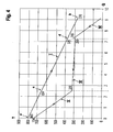
- FIG. 4 shows a TQ diagram, that is, a temperature-heat diagram for the system 1 according to FIG. 2 ,
- I the temperature-heat curve of the discharged from the fluidized bed 9 flue gas.
- the direct outlet of the flue gas from the fluidized bed furnace 9 is designated by a.
- the temperature of the flue gas at the exit from the fluidized bed combustion 9 is about 800 ° C, as shown FIG. 4 is apparent.
- the temperature-heat curve forms a monotonically decreasing straight line up to the point b, which forms the exit of the flue gas from the system 4.
- the outlet temperature of the flue gas is about 270 ° C.
- the flue gas is supplied within the system 4 the two air preheaters 15, 17 and the thermal oil heat exchanger 13, where the flue gas emits heat to the local heat exchanger media.
- FIG. 4 is denoted by II the temperature-heat curve of heated in the air preheater 15, the fluidized bed combustion 9 supplied combustion air.
- FIG. 4 III denotes the temperature-heat curve of the thermal oil of the thermal oil heat exchanger 13.
- FIG. 4 IV denotes the temperature-heat curve of the heated in the air preheater 17, introduced into the system 4 cold air.
- the slope of the curve II is greater than the slope of the curve I, since the amount of air in the air preheater 15 is considerably less than the amount of flue gas.
- the flue gas After heating the air in the air preheater 15, the flue gas is fed to the thermal oil heat exchanger 13. The flue gas releases heat to the thermal oil so that the flue gas cools from the temperature of 654 ° C (point c on curve I) to a temperature of about 375 ° C (point d on curve I).
- the flue gas is supplied from the outlet of the thermal oil heat exchanger 13 to the further air preheater 17, where the introduced into the system 4 cold air is heated.
- FIG. 4 can be seen by the heat emission of the flue gas, the air in the air preheater 17 from the temperature 375 ° C (point d on the curve I) to the outlet temperature 270 ° C (point b cooled on the curve I).
- the air in the air preheater 17 is heated from the inlet temperature 20 ° C (right end of the curve IV) to about 319 ° C (left end of the curve IV).
- Appendix 1 are to be interpreted as meaning that the exit temperature of the flue gas at exit from the system 4 is as low as possible, so that much heat of the flue gas is transferred to the components of the system 1, namely the thermal oil heat exchanger 13 and the air preheaters 15, 17.
- This requirement is in accordance with Appendix 1a FIG. 2 relatively well fulfilled, since the starting temperature of the flue gas (point b on the curve I) is about 270 ° C.
- Another requirement is that the distances between the curves II, III, IV to the temperature-heat curve of the flue gas are as large as possible, since then large temperature differences are realized in the system components, whereby the sizes of the system components can be selected small. Also this requirement is how out FIG. 4 can be seen in Appendix 1 according to FIG. 2 relatively well met.
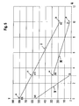
- FIG. 5 shows a TQ diagram for the system 1 according to FIG. 3 , Analogous to FIG. 4 is also referred to in the TQ diagram with I the temperature-heat curve of the flue gas.
- a is the direct exit of the flue gas from the fluidized bed 9, where the temperature of the flue gas is about 800 ° C.
- the temperature of the flue gas decreases until it leaves the system 4 to an outlet temperature of 182 ° C (point b of the curve I).
- FIG. 5 II denotes the temperature-heat curve of the combustion air in the air preheater 20.
- FIG. 5 III denotes the temperature of the sewage sludge, denoted by d (right end of curve III) the entry of the sewage sludge in the heat exchanger 18, and e designates the exit of the sewage sludge from the heat exchanger 18 or the inlet of sewage sludge in the fluidized bed 9 is.
- the flue gas is cooled from 800 ° C (point a of the curve I) to a temperature of about 615 ° C (point c of curve I).
- the combustion air for the fluidized bed combustion 9 in the air preheater 20 from a starting temperature of 20 ° C when entering the system 4 (right end of the curve II) is heated to a temperature of 548 ° C (left end of the curve II). Since the amount of flue gas is considerably larger than the amount of combustion air, the slope of the curve I for the flue gas is smaller than the slope of the curve II for the combustion air.
- the flue gas is cooled from the temperature 615 ° C (point c on the curve I) to the outlet temperature of the system 4 of 182 ° C (point b on the curve I).
- the sewage sludge is heated from a temperature of 20 ° C (point d on curve III) to a temperature of about 288 ° C (point e on curve III). Since the sewage sludge is under pressure, the water of the sludge remains in the liquid phase.
- the invention is not limited to the specific designs of the systems according to the FIGS. 4 and 5 limited.
- Plant designs are possible in which an exit temperature of the flue gas is obtained from the system 4, which is at 80 ° C or even lower.
Landscapes
- Engineering & Computer Science (AREA)
- Environmental & Geological Engineering (AREA)
- Water Supply & Treatment (AREA)
- Mechanical Engineering (AREA)
- General Engineering & Computer Science (AREA)
- Fluidized-Bed Combustion And Resonant Combustion (AREA)
- Treatment Of Sludge (AREA)
- Air Supply (AREA)
Priority Applications (1)
| Application Number | Priority Date | Filing Date | Title |
|---|---|---|---|
| PL10706501T PL2401552T3 (pl) | 2009-02-24 | 2010-02-06 | Sposób do samoistnego spalania osadu |
Applications Claiming Priority (2)
| Application Number | Priority Date | Filing Date | Title |
|---|---|---|---|
| DE102009010118A DE102009010118B4 (de) | 2009-02-24 | 2009-02-24 | Verfahren zur selbstgängigen Verbrennung von Klärschlamm |
| PCT/EP2010/000749 WO2010097162A1 (de) | 2009-02-24 | 2010-02-06 | Verfahren zur selbstgängigen verbrennung von schlamm |
Publications (2)
| Publication Number | Publication Date |
|---|---|
| EP2401552A1 EP2401552A1 (de) | 2012-01-04 |
| EP2401552B1 true EP2401552B1 (de) | 2012-11-21 |
Family
ID=42211934
Family Applications (1)
| Application Number | Title | Priority Date | Filing Date |
|---|---|---|---|
| EP10706501A Not-in-force EP2401552B1 (de) | 2009-02-24 | 2010-02-06 | Verfahren zur selbstgängigen verbrennung von schlamm |
Country Status (6)
| Country | Link |
|---|---|
| EP (1) | EP2401552B1 (pl) |
| DE (1) | DE102009010118B4 (pl) |
| DK (1) | DK2401552T3 (pl) |
| ES (1) | ES2395531T3 (pl) |
| PL (1) | PL2401552T3 (pl) |
| WO (1) | WO2010097162A1 (pl) |
Family Cites Families (13)
| Publication number | Priority date | Publication date | Assignee | Title |
|---|---|---|---|---|
| US4215637A (en) * | 1979-04-02 | 1980-08-05 | Envirotech Corporation | System for combustion of wet waste materials |
| DE3103417A1 (de) * | 1981-02-02 | 1982-08-12 | Saarberg-Fernwärme GmbH, 6600 Saarbrücken | Verfahren und vorrichtung zur oxidation von festen stoffen und waessrigen schlaemmen |
| DE3728398A1 (de) * | 1987-08-26 | 1989-03-09 | Bayer Ag | Verbrennen von waessrigen klaerschlaemmen nach dem wirbelschichtverfahren |
| ES2042869T3 (es) * | 1988-05-24 | 1993-12-16 | Siemens Ag | Procedimiento y dispositivo para el secado de lodos activados. |
| DD294684A5 (de) * | 1990-05-30 | 1991-10-10 | Petrolchemisches Kominat Schwedt,De | Verfahren zur aufarbeitung von wasserhaltigem oelschlamm |
| DE4217729A1 (de) * | 1992-05-29 | 1993-12-02 | Dessau Zement Maschbau Gmbh | Verfahren und anlagentechnische Schaltung zur Trocknung und Verbrennung von Abfallstoffen |
| DE4431564A1 (de) * | 1994-07-13 | 1996-01-18 | Kloeckner Humboldt Deutz Ag | Verfahren und anlagentechnische Schaltung zur Trocknung und Verbrennung von Klärschlamm |
| ATE196000T1 (de) * | 1994-12-06 | 2000-09-15 | Steinmueller Gmbh L & C | Verfahren zur verbrennung von klärschlamm und anlage zur durchführung des verfahrens |
| DE19604506C2 (de) * | 1995-02-23 | 1999-09-02 | Julia Innotec Gmbh | Verfahren zur Nutzung von bei der Verbrennung und/oder Vergasung von Klärschlamm anfallender Restwärmeenergie und Vorrichtung zur Nutzung dieser Restwärmeenergie |
| FR2758100B1 (fr) * | 1997-01-06 | 1999-02-12 | Youssef Bouchalat | Procede de traitement et valorisation energetique optimisee des boues de stations d'epuration urbaine et industrielle |
| DE19859052C2 (de) * | 1998-12-21 | 2001-01-25 | Dieter Steinbrecht | Verfahren und Einrichtung zur thermischen Abfallverwertung und Abfallentsorgung fester, flüssiger und pumpfähiger inhomogener brennbarer Gemische und thermische Reinigung kontaminierter Materialien in einer Wirbelschichtfeuerung |
| WO2001038818A1 (en) * | 1999-11-19 | 2001-05-31 | Munehiro Tokashiki | Scale with variable gauge |
| DE19956562A1 (de) * | 1999-11-24 | 2001-06-13 | Bbp Environment Gmbh | Verfahren zur Reinigung einer Wärmetauscherfläche und Feststoffblasmedium zur Durchführung des Verfahrens |
-
2009
- 2009-02-24 DE DE102009010118A patent/DE102009010118B4/de not_active Expired - Fee Related
-
2010
- 2010-02-06 WO PCT/EP2010/000749 patent/WO2010097162A1/de not_active Ceased
- 2010-02-06 EP EP10706501A patent/EP2401552B1/de not_active Not-in-force
- 2010-02-06 DK DK10706501.3T patent/DK2401552T3/da active
- 2010-02-06 PL PL10706501T patent/PL2401552T3/pl unknown
- 2010-02-06 ES ES10706501T patent/ES2395531T3/es active Active
Also Published As
| Publication number | Publication date |
|---|---|
| DE102009010118A1 (de) | 2010-09-02 |
| WO2010097162A1 (de) | 2010-09-02 |
| DE102009010118B4 (de) | 2011-03-31 |
| PL2401552T3 (pl) | 2013-04-30 |
| ES2395531T3 (es) | 2013-02-13 |
| DK2401552T3 (da) | 2013-01-21 |
| EP2401552A1 (de) | 2012-01-04 |
Similar Documents
| Publication | Publication Date | Title |
|---|---|---|
| DE2609330C3 (de) | Verfahren zur Umwandlung von anfänglich wasserhaltigen festen Abfallstoffen in wirtschaftlich nutzbare bzw. umweltunschädliche Produkte und Vorrichtung zur Durchführung des Verfahrens | |
| EP2230477B1 (de) | Holzspantrocknungsanlage zum Trocknen von Holzspänen und zugehöriges Verfahren zum Trocknen von Holzspänen | |
| DE2901723C2 (de) | Verfahren und Vorrichtung zum Trocknen eines Feststoffmaterials | |
| EP0343431B1 (de) | Verfahren und Einrichtung zum Trocknen von Klärschlamm | |
| EP2424955B1 (de) | Vorrichtung und verfahren zur trocknung und torrefizierung von wenigstens einem kohlenstoffhaltigen stoffstrom in einem etagenofen | |
| DE2940164C2 (de) | Verfahren zur Wärmerückgewinnung beim Trocknen fester Brennstoffe aus wasserhaltigen organischen Materialien | |
| EP0465479B1 (de) | Verfahren zur verwertung von klärschlamm | |
| WO2008095524A2 (de) | Verfahren und anlage zur trocknung von staubförmigen, insbesondere einer vergasung zuzuführenden brennstoffen | |
| EP0716264B1 (de) | Verfahren zur Verbrennung von Klärschlamm und Anlage zur Durchführung des Verfahrens | |
| WO2014009487A1 (de) | Verfahren zur behandlung von biomasse in einer anlage zur herstellung von zement und dazu korrespondierende anlage | |
| EP0851194A2 (de) | Trockner mit Abgasreinigung mittels thermischer Nachverbrennung | |
| EP1921375A2 (de) | Verfahren und Anordnung zur Mitverbrennung von Biomassen und/oder organischen Abfällen als Sekundärbrennstoff in einer Kohlenstaubfeuerung | |
| DE2902323A1 (de) | Verfahren und vorrichtung zum trocknen und behandeln von feuchtigkeit enthaltenden feststoffpartikeln mit organischen und/oder mineralischen anorganischen bestandteilen | |
| DE2810479C2 (de) | Verfahren zum Trocknen von Roh-Braunkohle in einer mit flüssigen Kohlenwasserstoffen hergestellten Einsatz-Suspension | |
| DE19531379C1 (de) | Verfahren zur Verbrennung von Klärschlamm und Anlage zur Durchführung des Verfahrens | |
| EP2401552B1 (de) | Verfahren zur selbstgängigen verbrennung von schlamm | |
| EP3891435B1 (de) | Verfahren zur brüdenverwertung und brüdenverwertungssystem | |
| DE2726157B2 (de) | Brennofenanlage für feste Güter | |
| EP0692679A2 (de) | Verfahren und anlagentechnische Schaltung zur Trocknung und Verbrennung von Klärschlamm | |
| DE2535683A1 (de) | Verfahren und vorrichtung zur verbrennung von schlaemmen mit hilfe rekuperativer schlammtrocknung | |
| DE19501736C1 (de) | Verfahren zur Verbrennung von Klärschlamm und Anlage zur Durchführung des Verfahrens | |
| EP3859207B1 (de) | Verbrennungsanlage mit wärmespeicher | |
| EP0571722A2 (de) | Verfahren und anlagentechnische Schaltung zur Trocknung und Verbrennung von Abfallstoffen | |
| DE3523677A1 (de) | Verfahren zum verbrennen von schlamm | |
| WO2018019861A1 (de) | Gestufte feuerung |
Legal Events
| Date | Code | Title | Description |
|---|---|---|---|
| PUAI | Public reference made under article 153(3) epc to a published international application that has entered the european phase |
Free format text: ORIGINAL CODE: 0009012 |
|
| 17P | Request for examination filed |
Effective date: 20110729 |
|
| AK | Designated contracting states |
Kind code of ref document: A1 Designated state(s): AT BE BG CH CY CZ DE DK EE ES FI FR GB GR HR HU IE IS IT LI LT LU LV MC MK MT NL NO PL PT RO SE SI SK SM TR |
|
| DAX | Request for extension of the european patent (deleted) | ||
| GRAP | Despatch of communication of intention to grant a patent |
Free format text: ORIGINAL CODE: EPIDOSNIGR1 |
|
| GRAS | Grant fee paid |
Free format text: ORIGINAL CODE: EPIDOSNIGR3 |
|
| RAP1 | Party data changed (applicant data changed or rights of an application transferred) |
Owner name: FRODENO, CHRISTA JOSEFINE |
|
| RIN1 | Information on inventor provided before grant (corrected) |
Inventor name: MICHAEL KADEN |
|
| GRAA | (expected) grant |
Free format text: ORIGINAL CODE: 0009210 |
|
| AK | Designated contracting states |
Kind code of ref document: B1 Designated state(s): AT BE BG CH CY CZ DE DK EE ES FI FR GB GR HR HU IE IS IT LI LT LU LV MC MK MT NL NO PL PT RO SE SI SK SM TR |
|
| REG | Reference to a national code |
Ref country code: GB Ref legal event code: FG4D Free format text: NOT ENGLISH |
|
| REG | Reference to a national code |
Ref country code: CH Ref legal event code: EP Ref country code: CH Ref legal event code: NV Representative=s name: ROTTMANN, ZIMMERMANN + PARTNER AG, CH |
|
| REG | Reference to a national code |
Ref country code: AT Ref legal event code: REF Ref document number: 585286 Country of ref document: AT Kind code of ref document: T Effective date: 20121215 |
|
| REG | Reference to a national code |
Ref country code: IE Ref legal event code: FG4D Free format text: LANGUAGE OF EP DOCUMENT: GERMAN |
|
| REG | Reference to a national code |
Ref country code: DE Ref legal event code: R096 Ref document number: 502010001698 Country of ref document: DE Effective date: 20130117 |
|
| REG | Reference to a national code |
Ref country code: DK Ref legal event code: T3 |
|
| REG | Reference to a national code |
Ref country code: ES Ref legal event code: FG2A Ref document number: 2395531 Country of ref document: ES Kind code of ref document: T3 Effective date: 20130213 |
|
| REG | Reference to a national code |
Ref country code: SE Ref legal event code: TRGR |
|
| REG | Reference to a national code |
Ref country code: NL Ref legal event code: T3 |
|
| REG | Reference to a national code |
Ref country code: NO Ref legal event code: T2 Effective date: 20121121 |
|
| PGFP | Annual fee paid to national office [announced via postgrant information from national office to epo] |
Ref country code: LU Payment date: 20130221 Year of fee payment: 4 |
|
| REG | Reference to a national code |
Ref country code: LT Ref legal event code: MG4D |
|
| PG25 | Lapsed in a contracting state [announced via postgrant information from national office to epo] |
Ref country code: LT Free format text: LAPSE BECAUSE OF FAILURE TO SUBMIT A TRANSLATION OF THE DESCRIPTION OR TO PAY THE FEE WITHIN THE PRESCRIBED TIME-LIMIT Effective date: 20121121 |
|
| PGFP | Annual fee paid to national office [announced via postgrant information from national office to epo] |
Ref country code: SE Payment date: 20130219 Year of fee payment: 4 Ref country code: CZ Payment date: 20130130 Year of fee payment: 4 Ref country code: FR Payment date: 20130301 Year of fee payment: 4 Ref country code: NO Payment date: 20130214 Year of fee payment: 4 Ref country code: IE Payment date: 20130219 Year of fee payment: 4 Ref country code: ES Payment date: 20130227 Year of fee payment: 4 Ref country code: FI Payment date: 20130213 Year of fee payment: 4 Ref country code: MC Payment date: 20130213 Year of fee payment: 4 Ref country code: DK Payment date: 20130218 Year of fee payment: 4 |
|
| REG | Reference to a national code |
Ref country code: PL Ref legal event code: T3 |
|
| PG25 | Lapsed in a contracting state [announced via postgrant information from national office to epo] |
Ref country code: SI Free format text: LAPSE BECAUSE OF FAILURE TO SUBMIT A TRANSLATION OF THE DESCRIPTION OR TO PAY THE FEE WITHIN THE PRESCRIBED TIME-LIMIT Effective date: 20121121 Ref country code: GR Free format text: LAPSE BECAUSE OF FAILURE TO SUBMIT A TRANSLATION OF THE DESCRIPTION OR TO PAY THE FEE WITHIN THE PRESCRIBED TIME-LIMIT Effective date: 20130222 Ref country code: PT Free format text: LAPSE BECAUSE OF FAILURE TO SUBMIT A TRANSLATION OF THE DESCRIPTION OR TO PAY THE FEE WITHIN THE PRESCRIBED TIME-LIMIT Effective date: 20130321 |
|
| PGFP | Annual fee paid to national office [announced via postgrant information from national office to epo] |
Ref country code: LV Payment date: 20130213 Year of fee payment: 4 Ref country code: PL Payment date: 20130123 Year of fee payment: 4 Ref country code: NL Payment date: 20130219 Year of fee payment: 4 Ref country code: BE Payment date: 20130220 Year of fee payment: 4 |
|
| PG25 | Lapsed in a contracting state [announced via postgrant information from national office to epo] |
Ref country code: SK Free format text: LAPSE BECAUSE OF FAILURE TO SUBMIT A TRANSLATION OF THE DESCRIPTION OR TO PAY THE FEE WITHIN THE PRESCRIBED TIME-LIMIT Effective date: 20121121 Ref country code: BG Free format text: LAPSE BECAUSE OF FAILURE TO SUBMIT A TRANSLATION OF THE DESCRIPTION OR TO PAY THE FEE WITHIN THE PRESCRIBED TIME-LIMIT Effective date: 20130221 Ref country code: EE Free format text: LAPSE BECAUSE OF FAILURE TO SUBMIT A TRANSLATION OF THE DESCRIPTION OR TO PAY THE FEE WITHIN THE PRESCRIBED TIME-LIMIT Effective date: 20121121 |
|
| PG25 | Lapsed in a contracting state [announced via postgrant information from national office to epo] |
Ref country code: RO Free format text: LAPSE BECAUSE OF FAILURE TO SUBMIT A TRANSLATION OF THE DESCRIPTION OR TO PAY THE FEE WITHIN THE PRESCRIBED TIME-LIMIT Effective date: 20121121 |
|
| PLBE | No opposition filed within time limit |
Free format text: ORIGINAL CODE: 0009261 |
|
| STAA | Information on the status of an ep patent application or granted ep patent |
Free format text: STATUS: NO OPPOSITION FILED WITHIN TIME LIMIT |
|
| 26N | No opposition filed |
Effective date: 20130822 |
|
| PG25 | Lapsed in a contracting state [announced via postgrant information from national office to epo] |
Ref country code: HR Free format text: LAPSE BECAUSE OF FAILURE TO SUBMIT A TRANSLATION OF THE DESCRIPTION OR TO PAY THE FEE WITHIN THE PRESCRIBED TIME-LIMIT Effective date: 20121121 |
|
| REG | Reference to a national code |
Ref country code: DE Ref legal event code: R097 Ref document number: 502010001698 Country of ref document: DE Effective date: 20130822 |
|
| PGFP | Annual fee paid to national office [announced via postgrant information from national office to epo] |
Ref country code: MT Payment date: 20130129 Year of fee payment: 4 |
|
| BERE | Be: lapsed |
Owner name: FRODENO, CHRISTA JOSEFINE Effective date: 20140228 |
|
| REG | Reference to a national code |
Ref country code: NL Ref legal event code: V1 Effective date: 20140901 |
|
| REG | Reference to a national code |
Ref country code: DK Ref legal event code: EBP Effective date: 20140228 |
|
| PG25 | Lapsed in a contracting state [announced via postgrant information from national office to epo] |
Ref country code: LU Free format text: LAPSE BECAUSE OF NON-PAYMENT OF DUE FEES Effective date: 20140206 Ref country code: MC Free format text: LAPSE BECAUSE OF NON-PAYMENT OF DUE FEES Effective date: 20140228 |
|
| REG | Reference to a national code |
Ref country code: SE Ref legal event code: EUG |
|
| GBPC | Gb: european patent ceased through non-payment of renewal fee |
Effective date: 20140206 |
|
| PG25 | Lapsed in a contracting state [announced via postgrant information from national office to epo] |
Ref country code: CZ Free format text: LAPSE BECAUSE OF NON-PAYMENT OF DUE FEES Effective date: 20140206 Ref country code: FI Free format text: LAPSE BECAUSE OF NON-PAYMENT OF DUE FEES Effective date: 20140206 Ref country code: NO Free format text: LAPSE BECAUSE OF NON-PAYMENT OF DUE FEES Effective date: 20140228 Ref country code: NL Free format text: LAPSE BECAUSE OF NON-PAYMENT OF DUE FEES Effective date: 20140901 |
|
| REG | Reference to a national code |
Ref country code: FR Ref legal event code: ST Effective date: 20141031 |
|
| PG25 | Lapsed in a contracting state [announced via postgrant information from national office to epo] |
Ref country code: LV Free format text: LAPSE BECAUSE OF NON-PAYMENT OF DUE FEES Effective date: 20140206 Ref country code: SE Free format text: LAPSE BECAUSE OF NON-PAYMENT OF DUE FEES Effective date: 20140207 |
|
| REG | Reference to a national code |
Ref country code: IE Ref legal event code: MM4A |
|
| PG25 | Lapsed in a contracting state [announced via postgrant information from national office to epo] |
Ref country code: FR Free format text: LAPSE BECAUSE OF NON-PAYMENT OF DUE FEES Effective date: 20140228 Ref country code: GB Free format text: LAPSE BECAUSE OF NON-PAYMENT OF DUE FEES Effective date: 20140206 Ref country code: DK Free format text: LAPSE BECAUSE OF NON-PAYMENT OF DUE FEES Effective date: 20140228 Ref country code: IE Free format text: LAPSE BECAUSE OF NON-PAYMENT OF DUE FEES Effective date: 20140206 Ref country code: BE Free format text: LAPSE BECAUSE OF NON-PAYMENT OF DUE FEES Effective date: 20140228 |
|
| PGFP | Annual fee paid to national office [announced via postgrant information from national office to epo] |
Ref country code: CH Payment date: 20150218 Year of fee payment: 6 |
|
| REG | Reference to a national code |
Ref country code: ES Ref legal event code: FD2A Effective date: 20150527 |
|
| PG25 | Lapsed in a contracting state [announced via postgrant information from national office to epo] |
Ref country code: SM Free format text: LAPSE BECAUSE OF FAILURE TO SUBMIT A TRANSLATION OF THE DESCRIPTION OR TO PAY THE FEE WITHIN THE PRESCRIBED TIME-LIMIT Effective date: 20121121 Ref country code: PL Free format text: LAPSE BECAUSE OF NON-PAYMENT OF DUE FEES Effective date: 20140206 |
|
| PGFP | Annual fee paid to national office [announced via postgrant information from national office to epo] |
Ref country code: AT Payment date: 20150219 Year of fee payment: 6 Ref country code: TR Payment date: 20150204 Year of fee payment: 6 |
|
| REG | Reference to a national code |
Ref country code: PL Ref legal event code: LAPE |
|
| PG25 | Lapsed in a contracting state [announced via postgrant information from national office to epo] |
Ref country code: CY Free format text: LAPSE BECAUSE OF FAILURE TO SUBMIT A TRANSLATION OF THE DESCRIPTION OR TO PAY THE FEE WITHIN THE PRESCRIBED TIME-LIMIT Effective date: 20121121 |
|
| PG25 | Lapsed in a contracting state [announced via postgrant information from national office to epo] |
Ref country code: HU Free format text: LAPSE BECAUSE OF FAILURE TO SUBMIT A TRANSLATION OF THE DESCRIPTION OR TO PAY THE FEE WITHIN THE PRESCRIBED TIME-LIMIT; INVALID AB INITIO Effective date: 20100206 Ref country code: ES Free format text: LAPSE BECAUSE OF NON-PAYMENT OF DUE FEES Effective date: 20140207 Ref country code: MK Free format text: LAPSE BECAUSE OF FAILURE TO SUBMIT A TRANSLATION OF THE DESCRIPTION OR TO PAY THE FEE WITHIN THE PRESCRIBED TIME-LIMIT Effective date: 20121121 |
|
| PG25 | Lapsed in a contracting state [announced via postgrant information from national office to epo] |
Ref country code: MT Free format text: LAPSE BECAUSE OF NON-PAYMENT OF DUE FEES Effective date: 20140228 |
|
| PG25 | Lapsed in a contracting state [announced via postgrant information from national office to epo] |
Ref country code: IT Free format text: LAPSE BECAUSE OF NON-PAYMENT OF DUE FEES Effective date: 20140206 Ref country code: IS Free format text: LAPSE BECAUSE OF FAILURE TO SUBMIT A TRANSLATION OF THE DESCRIPTION OR TO PAY THE FEE WITHIN THE PRESCRIBED TIME-LIMIT Effective date: 20121121 |
|
| REG | Reference to a national code |
Ref country code: DE Ref legal event code: R119 Ref document number: 502010001698 Country of ref document: DE Ref country code: DE Ref legal event code: R409 Ref document number: 502010001698 Country of ref document: DE |
|
| REG | Reference to a national code |
Ref country code: CH Ref legal event code: PL |
|
| REG | Reference to a national code |
Ref country code: AT Ref legal event code: MM01 Ref document number: 585286 Country of ref document: AT Kind code of ref document: T Effective date: 20160206 |
|
| REG | Reference to a national code |
Ref country code: DE Ref legal event code: R409 Ref document number: 502010001698 Country of ref document: DE |
|
| PG25 | Lapsed in a contracting state [announced via postgrant information from national office to epo] |
Ref country code: LI Free format text: LAPSE BECAUSE OF NON-PAYMENT OF DUE FEES Effective date: 20160229 Ref country code: CH Free format text: LAPSE BECAUSE OF NON-PAYMENT OF DUE FEES Effective date: 20160229 |
|
| PG25 | Lapsed in a contracting state [announced via postgrant information from national office to epo] |
Ref country code: AT Free format text: LAPSE BECAUSE OF NON-PAYMENT OF DUE FEES Effective date: 20160206 |
|
| PGFP | Annual fee paid to national office [announced via postgrant information from national office to epo] |
Ref country code: DE Payment date: 20160709 Year of fee payment: 7 |
|
| REG | Reference to a national code |
Ref country code: DE Ref legal event code: R119 Ref document number: 502010001698 Country of ref document: DE |
|
| PG25 | Lapsed in a contracting state [announced via postgrant information from national office to epo] |
Ref country code: DE Free format text: LAPSE BECAUSE OF NON-PAYMENT OF DUE FEES Effective date: 20170901 |
|
| PG25 | Lapsed in a contracting state [announced via postgrant information from national office to epo] |
Ref country code: MT Free format text: LAPSE BECAUSE OF NON-PAYMENT OF DUE FEES Effective date: 20140206 |
|
| PG25 | Lapsed in a contracting state [announced via postgrant information from national office to epo] |
Ref country code: TR Free format text: LAPSE BECAUSE OF NON-PAYMENT OF DUE FEES Effective date: 20160206 |