EP2401244B1 - Methods of making ceramic structures - Google Patents
Methods of making ceramic structures Download PDFInfo
- Publication number
- EP2401244B1 EP2401244B1 EP10706871.0A EP10706871A EP2401244B1 EP 2401244 B1 EP2401244 B1 EP 2401244B1 EP 10706871 A EP10706871 A EP 10706871A EP 2401244 B1 EP2401244 B1 EP 2401244B1
- Authority
- EP
- European Patent Office
- Prior art keywords
- firing
- day
- stage
- temperature
- cycle
- Prior art date
- Legal status (The legal status is an assumption and is not a legal conclusion. Google has not performed a legal analysis and makes no representation as to the accuracy of the status listed.)
- Active
Links
- 238000000034 method Methods 0.000 title claims description 31
- 239000000919 ceramic Substances 0.000 title description 67
- 238000010304 firing Methods 0.000 claims description 242
- 238000010438 heat treatment Methods 0.000 claims description 41
- JSKIRARMQDRGJZ-UHFFFAOYSA-N dimagnesium dioxido-bis[(1-oxido-3-oxo-2,4,6,8,9-pentaoxa-1,3-disila-5,7-dialuminabicyclo[3.3.1]nonan-7-yl)oxy]silane Chemical compound [Mg++].[Mg++].[O-][Si]([O-])(O[Al]1O[Al]2O[Si](=O)O[Si]([O-])(O1)O2)O[Al]1O[Al]2O[Si](=O)O[Si]([O-])(O1)O2 JSKIRARMQDRGJZ-UHFFFAOYSA-N 0.000 claims description 34
- 229910052878 cordierite Inorganic materials 0.000 claims description 32
- 230000000977 initiatory effect Effects 0.000 claims description 21
- 239000004927 clay Substances 0.000 description 74
- 208000005156 Dehydration Diseases 0.000 description 62
- 230000018044 dehydration Effects 0.000 description 62
- 238000006297 dehydration reaction Methods 0.000 description 62
- 238000005336 cracking Methods 0.000 description 50
- 239000011368 organic material Substances 0.000 description 48
- 230000001965 increasing effect Effects 0.000 description 20
- 239000000463 material Substances 0.000 description 20
- 238000006243 chemical reaction Methods 0.000 description 14
- 230000002265 prevention Effects 0.000 description 12
- 239000007789 gas Substances 0.000 description 11
- 239000011230 binding agent Substances 0.000 description 9
- 239000012530 fluid Substances 0.000 description 9
- 239000003795 chemical substances by application Substances 0.000 description 8
- 239000002994 raw material Substances 0.000 description 8
- 229920002472 Starch Polymers 0.000 description 7
- 239000007788 liquid Substances 0.000 description 7
- 239000008107 starch Substances 0.000 description 7
- 235000019698 starch Nutrition 0.000 description 7
- 230000001413 cellular effect Effects 0.000 description 6
- 229920003091 Methocel™ Polymers 0.000 description 5
- XLYOFNOQVPJJNP-UHFFFAOYSA-N water Substances O XLYOFNOQVPJJNP-UHFFFAOYSA-N 0.000 description 5
- IJGRMHOSHXDMSA-UHFFFAOYSA-N Atomic nitrogen Chemical compound N#N IJGRMHOSHXDMSA-UHFFFAOYSA-N 0.000 description 4
- 239000000654 additive Substances 0.000 description 4
- 230000008859 change Effects 0.000 description 4
- 238000002485 combustion reaction Methods 0.000 description 4
- 230000003111 delayed effect Effects 0.000 description 4
- 239000011148 porous material Substances 0.000 description 4
- 230000009466 transformation Effects 0.000 description 4
- QVGXLLKOCUKJST-UHFFFAOYSA-N atomic oxygen Chemical compound [O] QVGXLLKOCUKJST-UHFFFAOYSA-N 0.000 description 3
- 229910010293 ceramic material Inorganic materials 0.000 description 3
- -1 for example Substances 0.000 description 3
- 238000004519 manufacturing process Methods 0.000 description 3
- 230000007246 mechanism Effects 0.000 description 3
- 239000000203 mixture Substances 0.000 description 3
- 239000001301 oxygen Substances 0.000 description 3
- 229910052760 oxygen Inorganic materials 0.000 description 3
- 230000008569 process Effects 0.000 description 3
- 239000000454 talc Substances 0.000 description 3
- 229910052623 talc Inorganic materials 0.000 description 3
- PNEYBMLMFCGWSK-UHFFFAOYSA-N aluminium oxide Inorganic materials [O-2].[O-2].[O-2].[Al+3].[Al+3] PNEYBMLMFCGWSK-UHFFFAOYSA-N 0.000 description 2
- 210000003850 cellular structure Anatomy 0.000 description 2
- 239000003245 coal Substances 0.000 description 2
- 238000000354 decomposition reaction Methods 0.000 description 2
- 230000003247 decreasing effect Effects 0.000 description 2
- 230000000694 effects Effects 0.000 description 2
- 230000008030 elimination Effects 0.000 description 2
- 238000003379 elimination reaction Methods 0.000 description 2
- 230000002708 enhancing effect Effects 0.000 description 2
- 238000002474 experimental method Methods 0.000 description 2
- 238000000465 moulding Methods 0.000 description 2
- 229910052757 nitrogen Inorganic materials 0.000 description 2
- 239000013618 particulate matter Substances 0.000 description 2
- 230000002093 peripheral effect Effects 0.000 description 2
- 238000004904 shortening Methods 0.000 description 2
- 238000005245 sintering Methods 0.000 description 2
- 230000035882 stress Effects 0.000 description 2
- 230000008646 thermal stress Effects 0.000 description 2
- 238000000844 transformation Methods 0.000 description 2
- 229910000505 Al2TiO5 Inorganic materials 0.000 description 1
- 208000022010 Lhermitte-Duclos disease Diseases 0.000 description 1
- 229910052581 Si3N4 Inorganic materials 0.000 description 1
- 230000015572 biosynthetic process Effects 0.000 description 1
- 239000003054 catalyst Substances 0.000 description 1
- 210000004027 cell Anatomy 0.000 description 1
- 229920003086 cellulose ether Polymers 0.000 description 1
- 238000001816 cooling Methods 0.000 description 1
- 239000013078 crystal Substances 0.000 description 1
- 230000007547 defect Effects 0.000 description 1
- KZHJGOXRZJKJNY-UHFFFAOYSA-N dioxosilane;oxo(oxoalumanyloxy)alumane Chemical compound O=[Si]=O.O=[Si]=O.O=[Al]O[Al]=O.O=[Al]O[Al]=O.O=[Al]O[Al]=O KZHJGOXRZJKJNY-UHFFFAOYSA-N 0.000 description 1
- 230000007613 environmental effect Effects 0.000 description 1
- 238000001914 filtration Methods 0.000 description 1
- 239000003546 flue gas Substances 0.000 description 1
- 238000002309 gasification Methods 0.000 description 1
- 230000020169 heat generation Effects 0.000 description 1
- 239000001866 hydroxypropyl methyl cellulose Substances 0.000 description 1
- 229920003088 hydroxypropyl methyl cellulose Polymers 0.000 description 1
- 235000010979 hydroxypropyl methyl cellulose Nutrition 0.000 description 1
- UFVKGYZPFZQRLF-UHFFFAOYSA-N hydroxypropyl methyl cellulose Chemical compound OC1C(O)C(OC)OC(CO)C1OC1C(O)C(O)C(OC2C(C(O)C(OC3C(C(O)C(O)C(CO)O3)O)C(CO)O2)O)C(CO)O1 UFVKGYZPFZQRLF-UHFFFAOYSA-N 0.000 description 1
- 239000012212 insulator Substances 0.000 description 1
- QSHDDOUJBYECFT-UHFFFAOYSA-N mercury Chemical compound [Hg] QSHDDOUJBYECFT-UHFFFAOYSA-N 0.000 description 1
- 229910052753 mercury Inorganic materials 0.000 description 1
- 229920000609 methyl cellulose Polymers 0.000 description 1
- 239000001923 methylcellulose Substances 0.000 description 1
- 235000010981 methylcellulose Nutrition 0.000 description 1
- 229910052863 mullite Inorganic materials 0.000 description 1
- 230000003647 oxidation Effects 0.000 description 1
- 238000007254 oxidation reaction Methods 0.000 description 1
- AABBHSMFGKYLKE-SNAWJCMRSA-N propan-2-yl (e)-but-2-enoate Chemical compound C\C=C\C(=O)OC(C)C AABBHSMFGKYLKE-SNAWJCMRSA-N 0.000 description 1
- 230000009467 reduction Effects 0.000 description 1
- 230000035945 sensitivity Effects 0.000 description 1
- HBMJWWWQQXIZIP-UHFFFAOYSA-N silicon carbide Chemical compound [Si+]#[C-] HBMJWWWQQXIZIP-UHFFFAOYSA-N 0.000 description 1
- 229910010271 silicon carbide Inorganic materials 0.000 description 1
- HQVNEWCFYHHQES-UHFFFAOYSA-N silicon nitride Chemical compound N12[Si]34N5[Si]62N3[Si]51N64 HQVNEWCFYHHQES-UHFFFAOYSA-N 0.000 description 1
- 239000007787 solid Substances 0.000 description 1
- 239000004071 soot Substances 0.000 description 1
- 239000000758 substrate Substances 0.000 description 1
- 231100000701 toxic element Toxicity 0.000 description 1
- 238000011179 visual inspection Methods 0.000 description 1
- 230000004580 weight loss Effects 0.000 description 1
Images


Classifications
-
- C—CHEMISTRY; METALLURGY
- C04—CEMENTS; CONCRETE; ARTIFICIAL STONE; CERAMICS; REFRACTORIES
- C04B—LIME, MAGNESIA; SLAG; CEMENTS; COMPOSITIONS THEREOF, e.g. MORTARS, CONCRETE OR LIKE BUILDING MATERIALS; ARTIFICIAL STONE; CERAMICS; REFRACTORIES; TREATMENT OF NATURAL STONE
- C04B35/00—Shaped ceramic products characterised by their composition; Ceramics compositions; Processing powders of inorganic compounds preparatory to the manufacturing of ceramic products
- C04B35/622—Forming processes; Processing powders of inorganic compounds preparatory to the manufacturing of ceramic products
- C04B35/626—Preparing or treating the powders individually or as batches ; preparing or treating macroscopic reinforcing agents for ceramic products, e.g. fibres; mechanical aspects section B
- C04B35/63—Preparing or treating the powders individually or as batches ; preparing or treating macroscopic reinforcing agents for ceramic products, e.g. fibres; mechanical aspects section B using additives specially adapted for forming the products, e.g.. binder binders
- C04B35/638—Removal thereof
-
- C—CHEMISTRY; METALLURGY
- C04—CEMENTS; CONCRETE; ARTIFICIAL STONE; CERAMICS; REFRACTORIES
- C04B—LIME, MAGNESIA; SLAG; CEMENTS; COMPOSITIONS THEREOF, e.g. MORTARS, CONCRETE OR LIKE BUILDING MATERIALS; ARTIFICIAL STONE; CERAMICS; REFRACTORIES; TREATMENT OF NATURAL STONE
- C04B35/00—Shaped ceramic products characterised by their composition; Ceramics compositions; Processing powders of inorganic compounds preparatory to the manufacturing of ceramic products
- C04B35/01—Shaped ceramic products characterised by their composition; Ceramics compositions; Processing powders of inorganic compounds preparatory to the manufacturing of ceramic products based on oxide ceramics
- C04B35/16—Shaped ceramic products characterised by their composition; Ceramics compositions; Processing powders of inorganic compounds preparatory to the manufacturing of ceramic products based on oxide ceramics based on silicates other than clay
- C04B35/18—Shaped ceramic products characterised by their composition; Ceramics compositions; Processing powders of inorganic compounds preparatory to the manufacturing of ceramic products based on oxide ceramics based on silicates other than clay rich in aluminium oxide
- C04B35/195—Alkaline earth aluminosilicates, e.g. cordierite or anorthite
-
- C—CHEMISTRY; METALLURGY
- C04—CEMENTS; CONCRETE; ARTIFICIAL STONE; CERAMICS; REFRACTORIES
- C04B—LIME, MAGNESIA; SLAG; CEMENTS; COMPOSITIONS THEREOF, e.g. MORTARS, CONCRETE OR LIKE BUILDING MATERIALS; ARTIFICIAL STONE; CERAMICS; REFRACTORIES; TREATMENT OF NATURAL STONE
- C04B35/00—Shaped ceramic products characterised by their composition; Ceramics compositions; Processing powders of inorganic compounds preparatory to the manufacturing of ceramic products
- C04B35/622—Forming processes; Processing powders of inorganic compounds preparatory to the manufacturing of ceramic products
- C04B35/64—Burning or sintering processes
-
- C—CHEMISTRY; METALLURGY
- C04—CEMENTS; CONCRETE; ARTIFICIAL STONE; CERAMICS; REFRACTORIES
- C04B—LIME, MAGNESIA; SLAG; CEMENTS; COMPOSITIONS THEREOF, e.g. MORTARS, CONCRETE OR LIKE BUILDING MATERIALS; ARTIFICIAL STONE; CERAMICS; REFRACTORIES; TREATMENT OF NATURAL STONE
- C04B38/00—Porous mortars, concrete, artificial stone or ceramic ware; Preparation thereof
- C04B38/0006—Honeycomb structures
-
- C—CHEMISTRY; METALLURGY
- C04—CEMENTS; CONCRETE; ARTIFICIAL STONE; CERAMICS; REFRACTORIES
- C04B—LIME, MAGNESIA; SLAG; CEMENTS; COMPOSITIONS THEREOF, e.g. MORTARS, CONCRETE OR LIKE BUILDING MATERIALS; ARTIFICIAL STONE; CERAMICS; REFRACTORIES; TREATMENT OF NATURAL STONE
- C04B2111/00—Mortars, concrete or artificial stone or mixtures to prepare them, characterised by specific function, property or use
- C04B2111/00474—Uses not provided for elsewhere in C04B2111/00
- C04B2111/00793—Uses not provided for elsewhere in C04B2111/00 as filters or diaphragms
-
- C—CHEMISTRY; METALLURGY
- C04—CEMENTS; CONCRETE; ARTIFICIAL STONE; CERAMICS; REFRACTORIES
- C04B—LIME, MAGNESIA; SLAG; CEMENTS; COMPOSITIONS THEREOF, e.g. MORTARS, CONCRETE OR LIKE BUILDING MATERIALS; ARTIFICIAL STONE; CERAMICS; REFRACTORIES; TREATMENT OF NATURAL STONE
- C04B2235/00—Aspects relating to ceramic starting mixtures or sintered ceramic products
- C04B2235/65—Aspects relating to heat treatments of ceramic bodies such as green ceramics or pre-sintered ceramics, e.g. burning, sintering or melting processes
- C04B2235/656—Aspects relating to heat treatments of ceramic bodies such as green ceramics or pre-sintered ceramics, e.g. burning, sintering or melting processes characterised by specific heating conditions during heat treatment
- C04B2235/6562—Heating rate
-
- C—CHEMISTRY; METALLURGY
- C04—CEMENTS; CONCRETE; ARTIFICIAL STONE; CERAMICS; REFRACTORIES
- C04B—LIME, MAGNESIA; SLAG; CEMENTS; COMPOSITIONS THEREOF, e.g. MORTARS, CONCRETE OR LIKE BUILDING MATERIALS; ARTIFICIAL STONE; CERAMICS; REFRACTORIES; TREATMENT OF NATURAL STONE
- C04B2235/00—Aspects relating to ceramic starting mixtures or sintered ceramic products
- C04B2235/65—Aspects relating to heat treatments of ceramic bodies such as green ceramics or pre-sintered ceramics, e.g. burning, sintering or melting processes
- C04B2235/656—Aspects relating to heat treatments of ceramic bodies such as green ceramics or pre-sintered ceramics, e.g. burning, sintering or melting processes characterised by specific heating conditions during heat treatment
- C04B2235/6567—Treatment time
-
- C—CHEMISTRY; METALLURGY
- C04—CEMENTS; CONCRETE; ARTIFICIAL STONE; CERAMICS; REFRACTORIES
- C04B—LIME, MAGNESIA; SLAG; CEMENTS; COMPOSITIONS THEREOF, e.g. MORTARS, CONCRETE OR LIKE BUILDING MATERIALS; ARTIFICIAL STONE; CERAMICS; REFRACTORIES; TREATMENT OF NATURAL STONE
- C04B2235/00—Aspects relating to ceramic starting mixtures or sintered ceramic products
- C04B2235/65—Aspects relating to heat treatments of ceramic bodies such as green ceramics or pre-sintered ceramics, e.g. burning, sintering or melting processes
- C04B2235/66—Specific sintering techniques, e.g. centrifugal sintering
- C04B2235/661—Multi-step sintering
-
- Y—GENERAL TAGGING OF NEW TECHNOLOGICAL DEVELOPMENTS; GENERAL TAGGING OF CROSS-SECTIONAL TECHNOLOGIES SPANNING OVER SEVERAL SECTIONS OF THE IPC; TECHNICAL SUBJECTS COVERED BY FORMER USPC CROSS-REFERENCE ART COLLECTIONS [XRACs] AND DIGESTS
- Y10—TECHNICAL SUBJECTS COVERED BY FORMER USPC
- Y10T—TECHNICAL SUBJECTS COVERED BY FORMER US CLASSIFICATION
- Y10T428/00—Stock material or miscellaneous articles
- Y10T428/249921—Web or sheet containing structurally defined element or component
- Y10T428/249953—Composite having voids in a component [e.g., porous, cellular, etc.]
- Y10T428/249967—Inorganic matrix in void-containing component
- Y10T428/249969—Of silicon-containing material [e.g., glass, etc.]
Definitions
- the present teachings relate to methods of firing a green structure to produce a ceramic structure.
- Porous ceramic structures such as, for example, cordierite ceramic structures
- Such structures are generally prepared using a mixture of raw materials, which include, for example, for cordierite structures, base ceramic materials capable of forming cordierite upon firing (e.g., clay and talc), a binder (e.g., an organic cellulose ether, such as, for example, water-soluble methyl cellulose (methocel) or hydroxypropyl methyl cellulose), and a pore-forming agent (e.g., a starch).
- base ceramic materials capable of forming cordierite upon firing e.g., clay and talc
- a binder e.g., an organic cellulose ether, such as, for example, water-soluble methyl cellulose (methocel) or hydroxypropyl methyl cellulose
- a pore-forming agent e.g., a starch
- the mixture of raw materials is formed into a green structure, which is typically extruded to form a network of channels or cells (sometimes referred to as a honeycomb) configured to flow gas therethrough.
- the green structure is then fired to form the final ceramic product, such as, for example, cordierite particulate filters.
- Such particulate filters may include, but are not limited to, diesel particulate filters that are sometimes classified by their size and the type of vehicle and/or use for which the filters will be utilized.
- light-duty diesel (LDD) filters are typically 7 inches or less in diameter and are generally used in vehicles with unpredictable engine duty cycles (e.g., hard-duty cycles), such as, for example, passenger cars and light trucks.
- Heavy-duty (HDD) filters are typically 9 inches or greater in diameter and are generally used in vehicles with predictable engine duty cycles, such as, for example, large, heavy trucks (e.g., semis and/or other commercial hauling trucks).
- the firing temperature may be increased to a peak temperature over a relatively large time period so as to avoid heating the green structure too rapidly leading to cracking.
- EP1591428 describes a method for firing ceramic honeycomb structures with a volume of 5 litres or more to prevent firing defects such as cracks, in which a formed honeycomb material is heated from a temperature (180-300°C) at which the organic binder begins to burn to 300°C at a rate of 25°C/hr while keeping the temperature difference between the central portion of the formed honeycomb material and the firing atmosphere within a range of -80°C to +80°C.
- US2003/0143370 provides a porous honeycomb structure body and a method for manufacturing the same, in which the porosity and pore diameter in the center portion of the honeycomb structure body are larger than those in a peripheral portion.
- JP2002 160976 describes a method for manufacturing a honeycomb structure composed of cordierite ceramics, in which the sintering in the kiln is carried out at a programming rate of 100-200 degC/h in the binder elimination phase, 60-100 degC/h in the dehydration of crystal water phase, and 140-200 degC/h in the sintering phase.
- the present teachings may solve one or more of the above-mentioned problems and/or may demonstrate one or more of the above-mentioned desirable features. Other features and/or advantages may become apparent from the description that follows.
- the present teachings provide a method of firing a green structure to produce a ceramic structure according to claim 1.
- the method comprises heating a firing environment during a first stage of firing of a green structure over a first timed temperature cycle having an average ramp rate sufficient to substantially complete burnout of organic material prior to initiation of clay dehydration proximate a core of the ceramic structure.
- the method further comprises heating the firing environment during a second stage of the firing over a second timed temperature cycle having an average ramp rate that is faster than the average ramp rate of the first timed temperature cycle.
- the present teachings provide a porous ceramic structure made by a process comprising forming raw materials comprising clay material and organic material into a green structure and firing the green structure in a firing environment, wherein the firing comprises heating a firing environment up to and including a first threshold temperature over a first time period sufficient to substantially complete burnout of the organic material prior to initiation of dehydration of the clay material proximate a core of the green structure, and heating the firing environment from the first threshold temperature to a second threshold temperature higher than the first threshold temperature over a second time period during which clay dehydration occurs.
- An average ramp rate from the first threshold temperature to the second threshold temperature may range from about 11°C/hr to about 75°C/hr.
- the present teachings provide a method of firing a green structure to form a ceramic structure.
- the method may comprise heating a firing environment to a first threshold temperature over a first time period sufficient to substantially complete burnout of organic material proximate a core of a green structure prior to initiation of dehydration of clay material proximate the core region of the green structure.
- the method may further comprise heating the firing environment from the first threshold temperature to a second threshold temperature higher than the first threshold temperature over a second time period during which clay dehydration of the green structure occurs, wherein an average ramp rate from the first threshold temperature to the second threshold temperature ranges from about 11 °C/hr to about 75°C/hr.
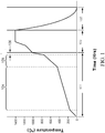
- the first two regimes include firing of the green structure, for example, in a gas-fired kiln, and the last includes cooling the formed ceramic structure. While not wishing to be bound by any particular theory, it is believed that during an initial regime 101 (e.g., a firing environment temperature up to about 1000 °C), the raw materials of the green structure are heated and individually undergo transformations, as will be explained in further detail below.
- an initial regime 101 e.g., a firing environment temperature up to about 1000 °C
- a second regime 102 the temperature of the firing environment is heated to a peak temperature, where it is held substantially constant over a time period permitting the green structure to react and form the ceramic structure.
- a firing environment temperature greater than or equal to about 1000 °C and up to a peak temperature
- the materials of the green structure begin to react with each other to form the ultimate ceramic material, such as, for example, cordierite.
- the formed ceramic structure is permitted to cool down from the peak firing temperature.
- the individual materials are believed to undergo various transformations.
- various hydrous materials e.g., hydrous alumina, hydrous clay, and talc
- various organic materials e.g., binder materials and/or pore forming agents (i.e., starch)
- burnout e.g., starch
- a first stage 104 for example, during which the firing environment temperature increases from about 180°C to about 425 °C, hydrous alumina loses water, methocel (or other binder material) burns out and starch (or other organic pore-forming agents) burnout.
- a second stage 105 for example, during which the firing environment temperature increases from about 425°C to about 750 °C, hydrous clay loses water.
- a third stage 106 for example, during which the firing environment temperature increases from about 750°C to about 1000 °C, talc loses water.
- the inventor believes the following events occur during the initial firing regime 101 described above.
- decomposition of the pore-forming agent occurs. This decomposition is an oxidation or exothermic reaction that releases large amounts of heat.
- the exothermic reaction occurs at the skin or outer portion of the ceramic structure, resulting in an initial thermal differential whereby the outer portion of the ceramic structure is hotter than the core.
- the exothermic reaction in the skin or outer portion subsides, and the exothermic reaction region moves into the interior and toward the core of the structure.
- the cellular structure that may be used for such filters comprises numerous channels, difficulties can be encountered in effectively removing, either by conduction or convection, the heat from the structure during firing.
- the cellular structure additionally provides a large surface area to promote binder reaction with oxygen (O 2 ) in the firing environment, thereby enhancing the interior exothermic effect. Consequently, during the organic material burnout (BO) stage (the first stage 104 described above), the structure can exhibit either a positive or a negative thermal differential (i.e., the core can exhibit either a higher or lower temperature than a location at or near the outer surface). This temperature differential can create thermal stresses in the porous ceramic structure, which may result in cracking. This phenomenon may be particularly true for large cellular ceramic structures or structures containing large amounts of organic materials, such as, for example, cordierite particulate filter products.
- ceramic structures such as, for example, cordierite particulate filters
- pore-forming agents i.e., starch
- ceramic structures can exhibit relatively high exothermic heat generation and relatively large core/skin temperature gradients during the firing process.
- Increasing the firing ramp rate (the rate of increasing the temperature in the firing environment), without allowing for proper conduction or convection of this heat from the structure's core, can create thermal stresses, which may ultimately result in internal cracking of the structure as the structure's core shrinks away from the structure's skin.
- various exemplary embodiments of the present teachings include methods of firing a green structure to produce a ceramic structure that avoid such mechanisms.
- the inventor has discovered that when a firing environment is heated up too quickly (e.g., over a shorter timed temperature cycle or increased ramp rate), there generally may not be enough oxygen (O 2 ) present in the environment to allow for timely burnout of the organic material (i.e., binder (e.g., methocel) and pore forming agents (e.g., starch)) in the core of the green structure prior to the next material transformation event.
- O 2 oxygen
- the organic material proximate the core therefore, does not burnout until a later time and at a higher temperature than is desirable, thereby causing stresses within the core of the structure which may lead to internal cracking.
- the exothermic reaction caused by organic material burnout in the core of the structure may be delayed by too quickly increasing the firing environment temperature, resulting in an overlap of the exothermic burnout events and the subsequent endothermic clay dehydration event. Consequently, the inventor has discovered that internal cracking occurs in a second stage of the initial firing regime due to this delayed exothermic reaction, which in turn causes an overlap of organic material burnout with clay dehydration proximate the structure's core. The inventor has further discovered that such cracking can be prevented by, for example, controlling the timed temperature cycle in the first stage of the initial firing regime.
- ⁇ T the maximum difference in temperature between the structure's core and the structure's skin
- ⁇ T the maximum core/skin temperature differential
- a green structure can withstand large negative core/skin temperature differentials (e.g., where a temperature taken at a location proximate a middle, core portion of the green structure is less than a temperature taken at a location proximate a top, skin portion of the green structure), but exhibits cracking when exposed to large positive core/skin temperature differentials (e.g., where a temperature taken at a location proximate a middle core portion of the green structure is greater than a temperature taken at a location proximate a top, skin portion of the green structure).
- a large positive core/skin temperature differential (e.g., a positive maximum difference in temperature ( ⁇ T)) in the clay stage of firing may indicate a delayed exothermic organic-burnout reaction in the core, and, therefore, an overlap of exothermic burnout with endothermic clay dehydration.
- a negative core/skin temperature differential (e.g., a negative maximum difference in temperature ( ⁇ T)) in the clay stage of firing may indicate that the above overlap was avoided.
- the present teachings contemplate methods of firing a green structure that reduce and/or eliminate internal cracking during firing by avoiding overlap of organic material burnout and clay dehydration transformation events proximate a core of the ceramic structure.
- the present teachings also contemplate minimizing a structure's firing cycle length while reducing and/or eliminating internal cracking.
- various exemplary embodiments of the present teachings consider methods of firing that combine the above two discoveries of heating a firing environment during a first stage of an initial firing regime over a first timed temperature cycle having an average ramp rate sufficient to substantially complete burnout of organic material prior to initiation of clay dehydration proximate a core of the ceramic structure (e.g., spending sufficient time in the BO stage to prevent overlap of organic-burnout and clay dehydration), and heating the firing environment during a second stage of the initial firing regime over a second, faster timed temperature cycle (e.g., using an increased average ramp rate during the clay dehydration stage to make up for the slower firing time during the first stage).
- the present teachings further contemplate methods of firing a green structure that reduce and/or eliminate internal cracking during firing by avoiding large positive core/skin temperature differentials (e.g., where a temperature taken at a location proximate a middle core portion of the green structure is greater than a temperature taken at a location proximate a top, skin portion of the green structure) during a second stage of the initial firing regime (i.e., the clay dehydration stage).
- large positive core/skin temperature differentials e.g., where a temperature taken at a location proximate a middle core portion of the green structure is greater than a temperature taken at a location proximate a top, skin portion of the green structure
- the present teachings provide methods of firing a green structure to produce a ceramic structure which allow for reduction of the length of time of the structure's firing cycle, while preventing internal cracking, thereby providing increased survivability for a broad range of product types without requiring the addition of expensive gases and/or other firing additives to the batch.
- firing cycles are disclosed for cordierite diesel filter products, such as, for example, light-duty diesel (LDD) filters and heavy-duty diesel (HDD) filters, conventionally used in diesel particulate filter (DPF) systems.
- ceramic structure refers to a ceramic article produced by forming raw materials comprising clay material and organic material (i.e., binder material and pore-forming agents) into a green structure and firing.
- exemplary ceramic structures include, for example, porous cellular ceramic structures, including, but not limited to, for example, particulate filter structures, industrial liquid filter structures and catalyst substrate structures.
- the particulate filter structures in accordance with exemplary embodiments of the present teachings may be capable of removing particulate matter from a fluid stream passing through the channels of the filter (e.g., LDD and HDD filters).
- Exemplary particulate filters of the present teachings may apply to the removal of any particulate matter from any fluid stream, and the fluid stream may be in the form of a gas or a liquid.
- the gas or liquid may also contain another phase, such as a solid particulate in either a gas or liquid stream, or droplets of liquid in a gas stream.
- Non-limiting, exemplary fluid streams include exhaust gases produced by internal combustion engines, such as, for example, diesel and gasoline engines, aqueous liquid streams, and coal combustion flue gases produced in a coal gasification process.
- LDD and HDD particulate filters are described, the present teachings apply to other porous ceramic structures used to filter fluid streams, including, but not limited to, for example, porous ceramic structures used for mercury and other toxic elements abatement and industrial liquid filtration applications.
- the ceramic structures in accordance with the present teachings can have any shape or geometry suitable for a particular application, as well as a variety of configurations and designs, including, but not limited to, for example, a wall-flow monolith structure, a flow-through monolith structure, or a partial-flow monolith structure (i.e., any combination of a wall-flow monolith structure and a flow-through monolith structure).
- exemplary wall-flow monoliths include, for example, any monolithic structure comprising channels or porous networks or other passages with individual passages open and plugged at opposite ends of the structure, thereby enhancing fluid flow through the channel walls of the monolith as the fluid flows from one end to the other.
- Exemplary flow-through monoliths include, for example, any monolithic structure comprising channels or porous networks or other passages with individual passages open at both ends, thereby permitting the flow of a fluid stream through the monolith passages from one end to an opposite end.
- Exemplary partial-flow monoliths include, for example, any monolithic structure that is partially wall-flow and partially flow-through.
- FIG. 2 illustrates one exemplary embodiment of a ceramic structure in accordance with the present teachings.
- the ceramic structure 200 has an inlet end 202 an outlet end 204 , and a plurality of channels 208 , 210 extending from the inlet end 202 to the outlet end 204 .
- the channels 208 , 210 are defined by intersecting porous walls 206 , thereby forming a generally cellular configuration (sometimes referred to as a honeycomb configuration by those ordinarily skilled in the art).
- channels 208, 210 can have various additional geometries, such as, for example, cross-sections that are circular, square, triangular, rectangular, hexagonal, sinusoidal, or any combination thereof, without departing from the scope of the present teachings.
- ceramic structure 200 is depicted as cylindrical, those skilled in the art would understand that such shape is exemplary only and ceramic structures produced in accordance with the present teachings may have a variety of shapes, including, but not limited to, block-shaped, cube-shaped, pyramid-shaped, etc.
- the ceramic structure 200 may be made of any suitable clay-based material. Exemplary materials include a variety of clay-based ceramic materials, including, but not limited to, cordierite, silicon carbide, silicon nitride, aluminum titanate, and mullite. In various exemplary embodiments, the ceramic structure 200 may be formed as a monolithic structure, for example, via extruding and/or molding of raw materials into a green structure that is then fired. Those having ordinary skill in the art are familiar with the various techniques for extruding and/or molding such green monolithic structures.
- Ceramic structures in various exemplary embodiments also may include a skin, for example skin 214 , forming an outer peripheral lateral surface of the structure.
- the skin may be made of the same or a different material than the porous walls, and in various embodiments may be thicker than the porous walls.
- the skin may be extruded and/or molded with the other portions of the green structure.
- the skin may be a separate structure wrapped around the outer portions of the channel network and fired with the channel network to create the ceramic structure.
- the overlap of organic material burnout (an exothermic event) and clay dehydration (an endothermic event) in a ceramic structure's core may lead to internal thermally-induced stresses, which result in internal cracking of the structure.
- the inventor has discovered that this overlap may be avoided; thereby increasing product survivability, by spending a predetermined amount of time (e.g., a predetermined minimum time period) at and/or under a threshold temperature to allow for organic material burnout to be substantially completed before clay dehydration begins.
- the present teachings contemplate accomplishing prevention of the overlap by heating the firing environment at a first, relatively slow timed temperature cycle during a first stage of the initial firing regime to substantially complete organic material burnout prior to initiation of clay dehydration proximate the core of the green structure, and then ramping up by heating the firing environment at a faster timed temperature cycle during a second stage of the initial firing regime.
- the present teachings contemplate that the overlap can be avoided by initially heating the firing environment at a relatively fast timed temperature cycle during a first stage of the initial firing regime, holding the firing environment at a threshold temperature for a period of time to allow for the substantial completion of organic material burnout prior to initiation of clay dehydration proximate the core, and then resume heating the firing environment at a relatively fast timed temperature cycle during a second stage of the initial firing regime.
- the present teachings contemplate selecting the timed temperature cycles so as to avoid the overlap of organic material burnout and clay dehydration events occurring proximate the core of the green structure while providing an overall shortened (e.g., minimized) time to completion of the initial firing regime and thereby a shortened (e.g., minimized) overall firing cycle time.
- firing cycle refers to the complete time-temperature profile starting with the initial firing regime through the completion of cool down to produce a ceramic structure.
- firing cycle encompasses each of the three general regimes (e.g., 101 , 102 , and 103 in FIG. 1 ) that occur during the structure's formation, and can include any number of different timed temperature cycles.
- timed temperature cycle refers to the change in firing environment temperature over a period of time, including, for example, variable rate temperature increases averaged over a period of time (i.e., variable ramp rates), constant temperature increases (i.e., constant ramp rates), temperature holds (i.e., holding constant at a certain temperature) and/or any combination thereof.
- a "first timed temperature cycle having an average ramp rate sufficient to substantially complete burnout of organic material prior to initiation of clay dehydration proximate the core of the ceramic structure” refers to a timed temperature cycle that provides about 90% or greater organic weight loss and/or completion of the exothermic reactions involving organic material proximate a core of the ceramic structure prior to the initiation of the endothermic event involving clay dehydration proximate a core of the structure, for example, resulting in negligible heat production at temperatures greater than or equal to about 400 °C, for example greater than or equal to about 425 °C.
- ⁇ T core/skin temperature differential
- ⁇ T core/skin temperature differential
- FIG. 4 looking for the presence of any large positive ⁇ T values (e.g., positive peaks) in the skin temperature range corresponding to the clay dehydration stage (e.g., about 400 °C to about 600 °C).
- Positive ⁇ T values greater than about 30 °C in any part of the clay dehydration stage can indicate that organic material burnout overlapped clay dehydration.
- the present teachings disclose the inventor's discovery of a theory of why internal cracking of a ceramic structure occurs during some firing cycles (e.g., those at relatively high firing ramp rates throughout the cycle) of a green structure. More specifically, internal cracking occurs in a second stage of an initial firing regime (e.g., during a clay dehydration stage) due to a delayed exothermic reaction, which in turn causes an overlap of organic material burnout with clay dehydration proximate a structure's core. To fully understand the problem, the inventor used experimental firing cycles to isolate these critical timed temperature cycles for various exemplary cordierite light-duty diesel filters, as shown and described below with reference to FIGS. 2-7 .
- the filters started to crack. That is, for the 3-Day cycle, 1 out of 6 of the 5.66" x 6" filters were observed to have cracked (i.e., 17%) and 3 out of 3 of the 7" x 6" filters were observed to have cracked (i.e., 100%).
- the main difference between the 4-Day cycle and 3-Day cycle was the timed temperature cycle employed during the first stage of firing in the initial firing regime (i.e., during the BO stage defined, in this case, as ranging from about 180 °C to about 425 °C). More specifically, the timed temperature cycle for the 4-Day cycle used an average ramp rate of about 9 °C/hr over this temperature range while the 3-Day cycle used an average ramp rate of about 25 °C/hr.
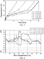
- core/skin temperature differential ( ⁇ T), calculated as the difference of the temperature proximate a middle, core portion of the filter and the temperature proximate an outer, top surface of the filter (T mid-core - T top-skin ), data was collected and plotted as a function of skin temperature for the 3-Day and 4-Day firing cycles of FIG. 3 , for the 5.66" x 6" cordierite light-duty diesel filters. As shown by FIG. 4 , a substantial change in the core/skin temperature differential occurred when the firing cycle was reduced from a 4-Day cycle to a 3-Day cycle.
- the 3-Day cycle exhibited a positive ⁇ T peak (i.e., a maximum positive core/skin temperature differential) in the skin temperature range of from about 400 °C to about 525 °C, corresponding to the clay dehydration stage.
- a positive ⁇ T peak i.e., a maximum positive core/skin temperature differential
- FIGS. 5-7 Further experiments were performed and the results illustrated in FIGS. 5-7 .
- various experimental firing cycles (4B-Day, 4C-Day, 4D-Day, 4E-Day, 4F-Day, 4G-Day and 4H-Day) were tested in addition to the cycles described above with reference to FIG. 3 for both 5.66" x 6" and 7" x 6" light-duty diesel filters.
- FIG. 5 As above, as shown in FIG.
- the 4B-Day, 4D-Day and 4E-Day cycles employed a slight increase in average ramp rate from the rate used in the 4-Day cycle during a first portion of the first stage of the initial firing regime (in this case, over a temperature range of from about 180°C to about 350 °C), with a more significant increase in average ramp rate employed during a second portion of the first stage (in this case, over a temperature range of from about 350 °C to about 425 °C).
- the 4B-Day, 4D-Day and 4E-Day cycles also respectively increased their average ramp rates during the second stage of the initial firing regime (i.e., a clay dehydration stage, in this case, over a temperature range of from about 425 °C to about 750 °C).
- the 4C-Day cycle employed a more significant increase in average ramp rate from the rate used in the 4-Day cycle during the first portion of the first stage of the initial firing regime (in this case, over a temperature range of from about 180°C to about 275 °C), and thereby an increase in initial average ramp rate from the rate used in the 4B-Day, 4D-Day and 4E-Day cycles over the temperature range of from about 180°C to about 350 °C, as well as an increase in the overall average ramp rate over the complete first stage of the initial firing regime (i.e., a BO stage, in this case, over the temperature range of from about 180°C to about 425 °C).
- the 4F-Day cycle employed the same approximate average ramp rate as the rate used in the 4-Day cycle during the first portion of the first stage of the initial firing regime (in this case, over the temperature range of from about 180°C to about 350 °C), with a significant increase in average ramp rate employed during the remaining portion of the first stage (in this case, over a temperature range of from about 350 °C to about 425 °C), which thereby resulted in an overall decrease in average ramp rate from the rate used in the 4B-Day, 4D-Day and 4E-Day cycles over the complete first stage of the initial firing regime (i.e., a BO stage, in this case, over the temperature range of from about 180°C to about 425 °C).
- the 4G-Day cycle employed the same approximate average ramp rate as the 3-Day cycle, up to an approximate 10-hour hold at 400 °C, during a first stage of the initial firing regime (i.e., a BO stage, in this case, over a temperature range of from about 180°C to about 425 °C), which thereby resulted in a relatively high initial average ramp rate from about 180°C to about 350 °C, followed by a relatively low average ramp rate from about 350 °C to about 425 °C.
- a first stage of the initial firing regime i.e., a BO stage, in this case, over a temperature range of from about 180°C to about 425 °C
- the 4H-Day cycle employed the same approximate ramp rate as the 3-Day cycle, up to an approximate 10 hour hold at 425 °C, during a first stage of the initial firing regime (i.e., a BO region, in this case, over a temperature range of from about 180 °C to about 425 °C), which thereby also resulted in a relatively high initial average ramp rate from about 180 °C to about 350 °C, followed by a relatively low average ramp rate from about 350 °C to about 425 °C.
- a first stage of the initial firing regime i.e., a BO region, in this case, over a temperature range of from about 180 °C to about 425 °C
- the 4G-Day and 4H-Day cycles resulted in an increase in average ramp rate from the rate used in the 4-Day cycle, and a slight decrease in average ramp rate from the rate used in the 4B-Day, 4D-Day and 4E-Day cycles, over the complete first stage of the initial firing regime (i.e., a BO stage, in this case, over the temperature range of from about 180 °C to about 425 °C).
- cycles 4B-Day, 4D-Day, 4E-Day, 4F-Day, 4G-Day and 4H-Day were crack free, however, cycle 4C-Day exhibited cracking in 50% of the 7" x 6" filters (2 out of 4 filters tested were observed to have cracked). Consequently, the inventor concluded that the ramp rates employed during the first stage of the initial firing regime (i.e., in the BO temperature region) are important to crack prevention. Once organic material burnout (e.g., burnout of methocel and starch) is complete, however, the inventor concluded that the average ramp rate can be increased freely without leading to cracking of the ceramic structure during firing.
- organic material burnout e.g., burnout of methocel and starch
- the average rate employed over a first stage of the initial firing regime for example, in a temperature range of from about 180 °C to about 425 °C, can influence internal cracking (see cycle 4C-Day), whereas, the average rate employed during the second stage of the initial firing regime, for example, in a temperature range of from about 425 °C to about 750 °C, does not have a significant influence (see cycles 4D-Day and 4E-Day).
- cycles 4B-Day, 4D-Day, 4E-Day, 4F-Day, 4G-Day and 4H-Day demonstrate prevention of internal cracking when using relatively short timed temperature cycles for the first and second stages of the initial firing regime (and thereby relatively short overall firing cycles), for example, wherein the time to completion of the second stage of the initial firing regime is less than or equal to about 39 hours for the experiments shown.
- timed temperature cycles may be used in accordance with exemplary embodiments of the present teachings, for example, for light-duty filters, wherein the time from the initiation of the firing cycle to the completion of the second stage is less than or equal to about 39 hours
- timed temperature cycles that result in a longer time to completion of the second stage, while still being less than the 80-hour time to completion of the second stage for the baseline 7-Day cycle described above, also are within the scope of the invention.
- the time from initiation of the firing cycle to the completion of the second stage of the initial firing regime may be less than or equal to about 62 hours.
- Table 3 Average Ramp Rates for the Firing Cycles Illustrated in FIG. 5 180° - 425°C Average Ramp Rate 180° - 350°C Average Ramp Rate 350° - 425°C Average Ramp Rate 425° to 750°C Average Ramp Rate 7-Day 4.7 3.6 8.1 19.6 6-Day 4.2 4.2 4.2 20 5-Day 5 5 5 20 4-Day 9 9 9 20 3-Day 25 25 25 4B-Day 12 9.7 25 25 4C-Day 14.8 12.5 25 25 4D-Day 12 9.7 25 50 4E-Day 12 9.7 25 75 4F-Day 11.2 9 25 50 4G-Day 11.8 25 5.4 25 4H-Day 11.8 25 5.4 25
- heating the firing environment during the first stage comprises heating the firing environment at an average ramp rate of less than or equal to about 12 °C/hr, for example, an average ramp rate ranging from about 4.2 °C/hr to about 12 °C/hr, (i.e., a timed temperature cycle encompassing any number of rates and holds utilized in the temperature range of from about 180 °C to about 425 °C but yielding an average ramp rate of less than or equal to about 12 °C
- heating the firing environment during the second stage of the initial firing regime comprises heating the firing environment at an average ramp rate of less than or equal to about 75 °C/hr, for example, an average ramp rate ranging from about 12 °C/hr to about 75 °C/hr, (i.e., a timed temperature cycle encompassing any number of rates utilized in the temperature range of from about 425 °C to about 750 °C but yielding an average ramp rate of less than or equal to about 75 °C/hr.)
- the first stage of the initial firing regime can also be broken down into two portions, a first portion in the temperature range of from about 180°C to about 350°C, and a second portion in the temperature range of from about 350°C to about 425°C, which correspond to two separate burnout events within the first stage of the initial firing regime.
- a first portion in the temperature range of from about 180°C to about 350°C and a second portion in the temperature range of from about 350°C to about 425°C, which correspond to two separate burnout events within the first stage of the initial firing regime.
- organic material burns out; however, an amount of char from the organic material remains.
- the remaining char of the organic material burns out.
- the inventor therefore concluded that the average ramp rate employed during each portion of the first stage of the initial firing regime also impacted crack prevention.
- cycles 4B-Day, 4D-Day, 4E-Day, 4F-Day, 4G-Day and 4H-Day demonstrate prevention of internal cracking when using a relatively short cycle for the first and second stages of the initial firing regime (and thereby a relatively short overall firing cycle), wherein heating the firing environment during the first stage comprises heating the firing environment from about 180 °C to about 350 °C at an average ramp rate of less than or equal to about 25 °C/hr, for example, an average ramp rate ranging from about 3.6 °C/hr to about 25 °C/hr, and heating the firing environment from about 350 °C to about 425 °C at an average ramp rate of less than or equal to about 25 °C/hr, for example, an average ramp rate ranging from about 4.2 °C/hr to about 25 °C/hr.
- FIG. 6 core/skin temperature differential ( ⁇ T) data was plotted as a function of skin temperature for the firing cycles of FIG. 5 for 5.66" x 6" cordierite light-duty diesel filters.
- each peak both negative and positive
- each peak can be related to a specific event in each firing cycle.
- the identification of these peaks which represent the relative maximum positive or relative maximum negative core/skin temperature differentials exhibited by the cordierite LDDs tested at the various firing cycles, help to explain the substantial change exhibited by the ⁇ T curve from the 4-Day cycle to the 3-Day cycle.
- the 3-Day cycle exhibited a positive ⁇ T peak (i.e., a maximum positive core/skin temperature differential) in a temperature range of from about 400°C to about 525°C (i.e. the clay dehydration stage indicated by reference number 602 in FIGS. 6-7 ).
- a positive ⁇ T peak i.e., a maximum positive core/skin temperature differential
- this large positive ⁇ T peak which exceeds about 30°C, was a result of a negative ⁇ T peak (i.e., a maximum negative core/skin temperature differential) at about 325°C. That is, because of the high heating rates in the first stage of the initial firing regime (i.e., the BO stage indicated by reference number 604 in FIGS.
- the temperature differential between the structure's core and the structure's skin increased, which in turn postponed the exothermic reaction in the core (i.e., burnout of binder and pore forming agent).
- the heat released from this exothermic reaction is not easily dissipated and causes the core temperature to remain higher relative to the skin temperature for a long period of time, therefore, causing an overlap (circled region 606 in FIGS. 6-8 ) between the exothermic reaction and the subsequent clay dehydration endothermic event.
- the structure is not given sufficient time to cool relative to the skin prior to initiation of clay dehydration, creating an overlap of the events, and high positive ⁇ T values (represented by a maximum positive core/skin temperature differential that exceeded about 30°C in the clay dehydration stage of the initial firing regime, that took place in the temperature range of from about 400°C to about 525°C of FIG. 6 ).
- high positive ⁇ T values represented by a maximum positive core/skin temperature differential that exceeded about 30°C in the clay dehydration stage of the initial firing regime, that took place in the temperature range of from about 400°C to about 525°C of FIG. 6 .
- the 3-Day cycle exhibited an overlap of organic material burnout and clay dehydration (the first and second stages of the initial firing regime), and thus resulted in internal cracking of the structure.
- each of the 4B-Day, 4D-Day, 4E-Day, 4F-Day, 4G-Day and 4H-Day cycles avoided this overlap for the 5.66" x 6" structures, as illustrated by the absence of any positive ⁇ T values exceeding about 30°C in the skin temperature range corresponding to the clay dehydration stage.
- ⁇ T core/skin temperature differential
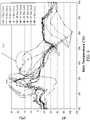
- FIG. 7 core/skin temperature differential ( ⁇ T) was plotted as a function of skin temperature for the firing cycles of FIG. 5 for 7" x 6" cordierite light-duty diesel filters.
- ⁇ T core/skin temperature differential
- a cycle that avoids the overlap of organic material burnout and clay dehydration proximate the core region of the green structure can lead to minimized or prevention of internal cracking.
- heating a firing environment during a first stage of the initial firing regime over a first timed temperature cycle having an average ramp rate sufficient to substantially complete burnout of organic material prior to initiation of clay dehydration in a core of a structure i.e., to avoid overlap
- the sign of the ⁇ T values e.g., the ⁇ T peak
- the clay dehydration stage can indicate whether or not organic material burnout was substantially complete prior to clay dehydration.
- Large positive ⁇ T values such as, for example, greater than about 30°C, can cause an overlap of the organic material burnout and clay dehydration events, thereby, causing the structure's core to shrink ahead of the structure's skin, resulting in internal cracks.
- the timed temperature cycle used in the first stage of the initial firing regime can be adjusted until there are no ⁇ T values which exceed 30°C in the second stage of the initial firing regime (i.e., the clay dehydration stage).
- a 7"x 6" cordierite LDD structure was fired using an experimental cycle that held the firing at a temperature of about 425°C over a time period, so that the structure developed high positive ⁇ T values during the first stage of the initial firing regime (i.e., the BO stage), but not for the second stage of the initial firing regime (i.e., the clay dehydration stage).
- a firing cycle that manages to avoid the overlap of organic material burnout and clay dehydration proximate the core of a green structure by firing the green structure up to and/or at a threshold temperature for a sufficient period of time (e.g., increasing the firing environment up to a threshold temperature within a minimum period of time, and/or holding the firing environment at a threshold temperature for a minimum period of time) during the first stage of the initial firing regime can lead to minimizing or prevention of internal cracking.
- heating a firing environment to a first threshold temperature over a first time period sufficient to substantially complete burnout of the organic material prior to initiation of dehydration of the clay material proximate a core region of the structure (i.e., to avoid overlap) can increase survivability.
- the present teachings may be applied to various filter sizes, including, for example, cordierite heavy-duty diesel (HDD) filters.
- HDD cordierite heavy-duty diesel
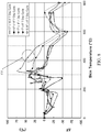
- FIG. 8 core/skin temperature differential ( ⁇ T) was plotted as a function of skin temperature for a 7-Day firing cycle for various LDD and HDD filter sizes, the results demonstrating the sensitivity of ⁇ T values, and therefore cracking, to size.
- a structure's size may affect internal cracking in a similar manner to that exhibited by shortening the timed temperature cycle during a first stage of the initial firing regime (i.e., increasing the temperature too quickly in the first stage).
- the positive ⁇ T values, exceeding about 30 °C, during the second stage of the initial firing regime were identified for the largest structure (i.e., the 13" x 18.5" HDD filter), in the range of about 400°C to about 525°C as depicted in FIG. 8 , as corresponding to internal cracking.
- the ramp rates employed during the first stage of the initial firing regime were then sufficiently slowed to resolve the overlap problem, thereby, reducing crack levels significantly in a 13" x 15" HDD filter with a new 8-Day firing cycle.
- FIG. 9 core/skin temperature differential ( ⁇ T) was plotted as a function of skin temperature for both the 7-Day firing cycle and the new 8-Day firing cycle for two roughly similarly sized HDD filters (13" x 18.5" and 13" x 15", respectively).
- ⁇ T core/skin temperature differential
- the 8-Day cycle showed negative ⁇ T values during the second stage of the initial firing regime corresponding to the temperature range from about 400 °C to about 600°C, thereby demonstrating that the burnout of organic material was completed prior to initiation of clay dehydration proximate the core of the ceramic structure.
- FIG. 10 illustrates the first and the second stages of the initial firing regime for the firing cycles of FIG. 9 .
- the 8-Day cycle demonstrated crack prevention for an HDD filter on a minimized firing cycle length of time, wherein heating the firing environment during the first stage included heating the firing environment at an average ramp rate of about 2.3°C/hr. And heating the firing environment during the second stage included heating the firing environment at an average ramp rate of about 11 °C/hr.
- heating the firing environment during the first stage comprises heating the firing environment at an average ramp rate of less than or equal to about 2.3 °C/hr (i.e., a timed temperature cycle encompassing any number of rates and holds utilized in the temperature range of from about 180°C to about 425°C yielding an average ramp rate of less than or equal to about 2.3 °C/hr).
- heating the firing environment during the second stage comprises heating the firing environment at an average ramp rate of less than or equal to about 11 °C/hr, for example, an average ramp rate ranging from about 2.3 °C/hr to about 11 °C/hr, (i.e., a timed temperature cycle encompassing any number of rates utilized in the temperature range of from about 425°C to about 750°C yielding an average ramp rate of less than or equal to about 11°C/hr).
- the present teachings thus provide methods of firing a green structure to produce a ceramic structure that minimize the firing cycle time for the ceramic structure to produce cordierite light-duty diesel filters and heavy-duty diesel filters, while also reducing and/or preventing cracking.
- various exemplary embodiments of the present teachings may avoid overlap of the occurrence of organic material burnout and clay dehydration stages proximate a core of the structure by spending a predetermined minimum time period below and/or at a threshold temperature to allow for organic-burnout.
- Various exemplary embodiments may accomplish this by heating a firing environment at a first timed temperature cycle, e.g., having a relatively slow average ramp rate, during a first stage of firing to substantially complete organic material burnout prior to initiation of clay dehydration proximate a core of the structure, and then ramping up by heating the firing environment at a second timed temperature cycle, e.g., having an average ramp rate that is faster than the average ramp rate of the first timed temperature cycle, during a second stage of firing (e.g., to minimize the overall firing cycle length by shortening the initial firing regime length of time).
- a first timed temperature cycle e.g., having a relatively slow average ramp rate
- Heating the firing environment during the first stage of the initial firing regime comprises heating the firing environment at a first average ramp rate of less than or equal to about 12 °C/hr over a temperature ranging from about 180 °C to a threshold temperature from 400 °C to 425 °C. The heating during the first stage is over a predetermined minimum time period that reanges from 24 to 48 hours.
- Heating the firing environment during the second stage of the initial firing regime i.e., the clay dehydration stage
- the second average ramp rate is faster than the first average ramp rate.
- the time from initiation of firing to completion of the second stage is 39 hours to 62 hours.
- ⁇ T core/skin temperature differential
- Various exemplary embodiments of the present teachings further contemplate methods of firing a green structure to produce a ceramic structure, which methods employ various gases and firing additives, such as, for example, nitrogen, in conjunction with the above teachings.
- Nitrogen for example, may delay the organic material burnout exothermic reaction until after the clay dehydration endothermic event, therefore, also avoiding overlap of the organic-burnout and clay dehydration stages to reduce or prevent cracking.
- gases and firing additives such as, for example, nitrogen, in conjunction with the above teachings.
- Nitrogen may delay the organic material burnout exothermic reaction until after the clay dehydration endothermic event, therefore, also avoiding overlap of the organic-burnout and clay dehydration stages to reduce or prevent cracking.
- Those ordinarily skilled in the art would understand how to utilize the present teachings in combination with various additional conventional firing methods to further minimize the overall firing cycle time, while reducing and/or eliminating internal cracking.
Landscapes
- Chemical & Material Sciences (AREA)
- Engineering & Computer Science (AREA)
- Ceramic Engineering (AREA)
- Manufacturing & Machinery (AREA)
- Materials Engineering (AREA)
- Structural Engineering (AREA)
- Organic Chemistry (AREA)
- Inorganic Chemistry (AREA)
- Filtering Materials (AREA)
- Porous Artificial Stone Or Porous Ceramic Products (AREA)
- Processes For Solid Components From Exhaust (AREA)
- Compositions Of Oxide Ceramics (AREA)
Priority Applications (1)
| Application Number | Priority Date | Filing Date | Title |
|---|---|---|---|
| PL10706871T PL2401244T3 (pl) | 2009-02-27 | 2010-02-26 | Sposoby produkcji ceramicznych struktur |
Applications Claiming Priority (2)
| Application Number | Priority Date | Filing Date | Title |
|---|---|---|---|
| US12/394,874 US8444737B2 (en) | 2009-02-27 | 2009-02-27 | Ceramic structures and methods of making ceramic structures |
| PCT/US2010/025478 WO2010099366A1 (en) | 2009-02-27 | 2010-02-26 | Ceramic structures and methods of making ceramic structures |
Publications (2)
| Publication Number | Publication Date |
|---|---|
| EP2401244A1 EP2401244A1 (en) | 2012-01-04 |
| EP2401244B1 true EP2401244B1 (en) | 2017-10-11 |
Family
ID=42133666
Family Applications (1)
| Application Number | Title | Priority Date | Filing Date |
|---|---|---|---|
| EP10706871.0A Active EP2401244B1 (en) | 2009-02-27 | 2010-02-26 | Methods of making ceramic structures |
Country Status (6)
| Country | Link |
|---|---|
| US (1) | US8444737B2 (zh) |
| EP (1) | EP2401244B1 (zh) |
| JP (2) | JP2012519137A (zh) |
| CN (1) | CN102414145B (zh) |
| PL (1) | PL2401244T3 (zh) |
| WO (1) | WO2010099366A1 (zh) |
Families Citing this family (13)
| Publication number | Priority date | Publication date | Assignee | Title |
|---|---|---|---|---|
| US9034199B2 (en) | 2012-02-21 | 2015-05-19 | Applied Materials, Inc. | Ceramic article with reduced surface defect density and process for producing a ceramic article |
| US9212099B2 (en) | 2012-02-22 | 2015-12-15 | Applied Materials, Inc. | Heat treated ceramic substrate having ceramic coating and heat treatment for coated ceramics |
| US9090046B2 (en) | 2012-04-16 | 2015-07-28 | Applied Materials, Inc. | Ceramic coated article and process for applying ceramic coating |
| US9604249B2 (en) | 2012-07-26 | 2017-03-28 | Applied Materials, Inc. | Innovative top-coat approach for advanced device on-wafer particle performance |
| US9343289B2 (en) | 2012-07-27 | 2016-05-17 | Applied Materials, Inc. | Chemistry compatible coating material for advanced device on-wafer particle performance |
| US9133062B2 (en) * | 2012-11-21 | 2015-09-15 | Corning Incorporated | Method of firing cordierite bodies |
| US10000424B2 (en) | 2013-03-08 | 2018-06-19 | Corning Incorporated | Fast firing method for ceramics |
| US9865434B2 (en) | 2013-06-05 | 2018-01-09 | Applied Materials, Inc. | Rare-earth oxide based erosion resistant coatings for semiconductor application |
| US9850568B2 (en) | 2013-06-20 | 2017-12-26 | Applied Materials, Inc. | Plasma erosion resistant rare-earth oxide based thin film coatings |
| US9452578B2 (en) * | 2013-07-26 | 2016-09-27 | Corning Incorporated | Fast firing method for high porosity ceramics |
| US9446560B2 (en) * | 2013-07-26 | 2016-09-20 | Corning Incorporated | Fast firing method for high porosity ceramics |
| US10472289B2 (en) | 2015-05-07 | 2019-11-12 | Corning Incorporated | Method of firing a ceramic honeycomb body |
| US11047035B2 (en) | 2018-02-23 | 2021-06-29 | Applied Materials, Inc. | Protective yttria coating for semiconductor equipment parts |
Family Cites Families (30)
| Publication number | Priority date | Publication date | Assignee | Title |
|---|---|---|---|---|
| JP2543565B2 (ja) | 1988-03-31 | 1996-10-16 | 日本碍子株式会社 | セラミックスの焼成に用いるトンネル炉 |
| JP3022195B2 (ja) | 1994-09-05 | 2000-03-15 | 日本碍子株式会社 | セラミック成形体の焼成法およびそれに用いる燃焼装置 |
| JP3138656B2 (ja) | 1997-03-28 | 2001-02-26 | 日本碍子株式会社 | セラミック成形体の焼成方法 |
| CN1210835A (zh) | 1997-07-28 | 1999-03-17 | 康宁股份有限公司 | 烧成时间显著缩短的堇青石物体的制备方法 |
| EP0894776B1 (en) | 1997-07-28 | 2003-09-10 | Corning Incorporated | Method of producing fast-fired cordierite bodies |
| JP3202945B2 (ja) | 1997-09-02 | 2001-08-27 | 日本碍子株式会社 | セラミックハニカム構造体の焼成方法 |
| WO1999018047A1 (en) | 1997-10-03 | 1999-04-15 | Corning Incorporated | Method for firing ceramic honeycomb bodies |
| ID27824A (id) | 1997-12-02 | 2001-04-26 | Corning Inc | Metode untuk membakar bodi sarang-lebah keramik |
| JP2001524450A (ja) | 1997-12-02 | 2001-12-04 | コーニング インコーポレイテッド | セラミックハニカム体の焼成方法 |
| US20020003322A1 (en) | 1998-11-24 | 2002-01-10 | Dull Alan T. | Method for firing ceramic honeycomb bodies |
| JP3340689B2 (ja) * | 1999-02-03 | 2002-11-05 | 日本碍子株式会社 | コージェライト質セラミックハニカム構造体の製造方法 |
| US6287510B1 (en) | 1999-11-23 | 2001-09-11 | Corning Incorporated | Method of firing green structures containing organics |
| US6344635B2 (en) | 1999-12-28 | 2002-02-05 | Corning Incorporated | Hybrid method for firing of ceramics |
| JP2003518473A (ja) | 1999-12-28 | 2003-06-10 | コーニング インコーポレイテッド | セラミックを焼成するためのハイブリッド方法 |
| WO2001063194A1 (en) | 2000-02-22 | 2001-08-30 | Corning Incorporated | Method for controlling the firing of ceramics |
| GB2360042A (en) * | 2000-03-10 | 2001-09-12 | Exxonmobil Res & Eng Co | Low sulphur fuel composition |
| JP2002160976A (ja) | 2000-11-21 | 2002-06-04 | Hitachi Metals Ltd | セラミックハニカム構造体の製造方法 |
| JP4030320B2 (ja) * | 2001-03-22 | 2008-01-09 | 株式会社デンソー | セラミック体およびセラミック触媒体 |
| US6827754B2 (en) * | 2001-09-13 | 2004-12-07 | Hitachi Metals, Ltd. | Ceramic honeycomb filter |
| JP2003212672A (ja) | 2002-01-21 | 2003-07-30 | Ngk Insulators Ltd | 多孔質セラミックス構造体の製造方法 |
| US7429351B2 (en) | 2002-01-21 | 2008-09-30 | Ngk Insulators, Ltd. | Method for manufacturing a porous ceramic structure |
| JP2003277162A (ja) | 2002-01-21 | 2003-10-02 | Ngk Insulators Ltd | 多孔質ハニカム構造体、その用途及びその製造方法 |
| JP4311609B2 (ja) | 2002-07-26 | 2009-08-12 | 日本碍子株式会社 | 多孔質セラミックス体の製造方法 |
| JP4222600B2 (ja) | 2003-01-07 | 2009-02-12 | 日本碍子株式会社 | セラミックハニカム構造体の焼成方法 |
| US7238319B2 (en) * | 2003-06-26 | 2007-07-03 | Corning Incorporated | Method for fabricating ceramic articles containing organic compounds |
| JP4358662B2 (ja) | 2004-03-23 | 2009-11-04 | 日本碍子株式会社 | コーディエライト質ハニカム構造体の製造方法 |
| JP4528153B2 (ja) * | 2005-02-23 | 2010-08-18 | 日本碍子株式会社 | 目封止ハニカム構造体の製造方法 |
| JP2006232590A (ja) * | 2005-02-23 | 2006-09-07 | Ngk Insulators Ltd | セラミック構造体の製造方法 |
| US20060244165A1 (en) * | 2005-04-27 | 2006-11-02 | Dai Huang | Manufacturing carbon fiber reinforced ceramics as brake discs |
| BRPI0615956A2 (pt) * | 2005-08-23 | 2011-05-31 | Dow Global Technologies Inc | método para remover um aditivo orgánico de uma colméia de cerámica |
-
2009
- 2009-02-27 US US12/394,874 patent/US8444737B2/en active Active
-
2010
- 2010-02-26 WO PCT/US2010/025478 patent/WO2010099366A1/en active Application Filing
- 2010-02-26 PL PL10706871T patent/PL2401244T3/pl unknown
- 2010-02-26 EP EP10706871.0A patent/EP2401244B1/en active Active
- 2010-02-26 JP JP2011552168A patent/JP2012519137A/ja active Pending
- 2010-02-26 CN CN201080019240.6A patent/CN102414145B/zh active Active
-
2015
- 2015-03-04 JP JP2015042277A patent/JP5957110B2/ja active Active
Non-Patent Citations (1)
| Title |
|---|
| None * |
Also Published As
| Publication number | Publication date |
|---|---|
| CN102414145A (zh) | 2012-04-11 |
| US20100218472A1 (en) | 2010-09-02 |
| WO2010099366A1 (en) | 2010-09-02 |
| PL2401244T3 (pl) | 2017-12-29 |
| EP2401244A1 (en) | 2012-01-04 |
| JP2012519137A (ja) | 2012-08-23 |
| JP5957110B2 (ja) | 2016-07-27 |
| US8444737B2 (en) | 2013-05-21 |
| CN102414145B (zh) | 2014-07-16 |
| JP2015129088A (ja) | 2015-07-16 |
Similar Documents
| Publication | Publication Date | Title |
|---|---|---|
| EP2401244B1 (en) | Methods of making ceramic structures | |
| JP5687681B2 (ja) | 4ウエイ排気ガス処理のための高多孔度フィルタ | |
| JP4495152B2 (ja) | ハニカム構造体及びその製造方法 | |
| US7947355B2 (en) | High porosity thermally shock resistant ceramic structures | |
| CN107489493B (zh) | 蜂窝过滤器 | |
| JPS6036364A (ja) | チタン酸アルミニウム−ムライト系セラミツク体ならびにこれを用いた木材スト−ブ燃焼室用コンバ−タ−手段およびジ−ゼル微粒子フイルタ− | |
| KR20040023790A (ko) | 다공질 세라믹체의 제조 방법 | |
| US9890673B2 (en) | Honeycomb filter | |
| WO2012157421A1 (ja) | ハニカムフィルタ | |
| JP2004315346A (ja) | ハニカム構造体 | |
| JP2013039514A (ja) | ハニカム構造体 | |
| JP6611707B2 (ja) | コージエライト対ムライトの比率が高いコージエライト・ムライト・チタン酸アルミニウムマグネシウム組成物およびそれから構成されたセラミック物品 | |
| JP2012188346A (ja) | ハニカム成形体の焼成方法およびこれを用いて得られるハニカム構造体ならびにこれを備えたガス処理装置 | |
| JP2012254440A (ja) | ハニカムフィルタ | |
| JP2008119665A (ja) | 排ガス浄化フィルタの製造方法 | |
| CN107486190B (zh) | 蜂窝结构体 | |
| KR20110011641A (ko) | 탄화규소 및 알루미늄 티타네이트를 함유하는 촉매 필터 또는 기재 | |
| WO2012157422A1 (ja) | ハニカムフィルタ | |
| JP2008137872A (ja) | ハニカム構造体 | |
| JP2008136981A (ja) | ハニカム構造体 | |
| US11505504B2 (en) | Non-oxide inorganic pore-formers for cordierite ceramic articles | |
| JP4699885B2 (ja) | ハニカム構造体の製造方法 | |
| JP3145450B2 (ja) | パティキュレートフィルタ | |
| US9546115B2 (en) | Honeycomb element with reinforced corners | |
| JP4811189B2 (ja) | 排ガス浄化用フィルタ基材の製造方法 |
Legal Events
| Date | Code | Title | Description |
|---|---|---|---|
| PUAI | Public reference made under article 153(3) epc to a published international application that has entered the european phase |
Free format text: ORIGINAL CODE: 0009012 |
|
| 17P | Request for examination filed |
Effective date: 20110923 |
|
| AK | Designated contracting states |
Kind code of ref document: A1 Designated state(s): AT BE BG CH CY CZ DE DK EE ES FI FR GB GR HR HU IE IS IT LI LT LU LV MC MK MT NL NO PL PT RO SE SI SK SM TR |
|
| DAX | Request for extension of the european patent (deleted) | ||
| 17Q | First examination report despatched |
Effective date: 20140829 |
|
| REG | Reference to a national code |
Ref country code: DE Ref legal event code: R079 Ref document number: 602010045874 Country of ref document: DE Free format text: PREVIOUS MAIN CLASS: C04B0035638000 Ipc: C04B0035640000 |
|
| GRAP | Despatch of communication of intention to grant a patent |
Free format text: ORIGINAL CODE: EPIDOSNIGR1 |
|
| RIC1 | Information provided on ipc code assigned before grant |
Ipc: C04B 38/00 20060101ALI20170329BHEP Ipc: C04B 35/638 20060101ALI20170329BHEP Ipc: C04B 35/195 20060101ALI20170329BHEP Ipc: C04B 35/64 20060101AFI20170329BHEP |
|
| INTG | Intention to grant announced |
Effective date: 20170420 |
|
| GRAS | Grant fee paid |
Free format text: ORIGINAL CODE: EPIDOSNIGR3 |
|
| GRAA | (expected) grant |
Free format text: ORIGINAL CODE: 0009210 |
|
| AK | Designated contracting states |
Kind code of ref document: B1 Designated state(s): AT BE BG CH CY CZ DE DK EE ES FI FR GB GR HR HU IE IS IT LI LT LU LV MC MK MT NL NO PL PT RO SE SI SK SM TR |
|
| REG | Reference to a national code |
Ref country code: GB Ref legal event code: FG4D |
|
| REG | Reference to a national code |
Ref country code: CH Ref legal event code: EP |
|
| REG | Reference to a national code |
Ref country code: IE Ref legal event code: FG4D |
|
| REG | Reference to a national code |
Ref country code: AT Ref legal event code: REF Ref document number: 935854 Country of ref document: AT Kind code of ref document: T Effective date: 20171115 |
|
| REG | Reference to a national code |
Ref country code: DE Ref legal event code: R096 Ref document number: 602010045874 Country of ref document: DE |
|
| REG | Reference to a national code |
Ref country code: FR Ref legal event code: PLFP Year of fee payment: 9 |
|
| REG | Reference to a national code |
Ref country code: NL Ref legal event code: MP Effective date: 20171011 |
|
| REG | Reference to a national code |
Ref country code: LT Ref legal event code: MG4D |
|
| REG | Reference to a national code |
Ref country code: AT Ref legal event code: MK05 Ref document number: 935854 Country of ref document: AT Kind code of ref document: T Effective date: 20171011 |
|
| PG25 | Lapsed in a contracting state [announced via postgrant information from national office to epo] |
Ref country code: NL Free format text: LAPSE BECAUSE OF FAILURE TO SUBMIT A TRANSLATION OF THE DESCRIPTION OR TO PAY THE FEE WITHIN THE PRESCRIBED TIME-LIMIT Effective date: 20171011 |
|
| PG25 | Lapsed in a contracting state [announced via postgrant information from national office to epo] |
Ref country code: ES Free format text: LAPSE BECAUSE OF FAILURE TO SUBMIT A TRANSLATION OF THE DESCRIPTION OR TO PAY THE FEE WITHIN THE PRESCRIBED TIME-LIMIT Effective date: 20171011 Ref country code: NO Free format text: LAPSE BECAUSE OF FAILURE TO SUBMIT A TRANSLATION OF THE DESCRIPTION OR TO PAY THE FEE WITHIN THE PRESCRIBED TIME-LIMIT Effective date: 20180111 Ref country code: LT Free format text: LAPSE BECAUSE OF FAILURE TO SUBMIT A TRANSLATION OF THE DESCRIPTION OR TO PAY THE FEE WITHIN THE PRESCRIBED TIME-LIMIT Effective date: 20171011 Ref country code: FI Free format text: LAPSE BECAUSE OF FAILURE TO SUBMIT A TRANSLATION OF THE DESCRIPTION OR TO PAY THE FEE WITHIN THE PRESCRIBED TIME-LIMIT Effective date: 20171011 Ref country code: SE Free format text: LAPSE BECAUSE OF FAILURE TO SUBMIT A TRANSLATION OF THE DESCRIPTION OR TO PAY THE FEE WITHIN THE PRESCRIBED TIME-LIMIT Effective date: 20171011 |
|
| PG25 | Lapsed in a contracting state [announced via postgrant information from national office to epo] |
Ref country code: BG Free format text: LAPSE BECAUSE OF FAILURE TO SUBMIT A TRANSLATION OF THE DESCRIPTION OR TO PAY THE FEE WITHIN THE PRESCRIBED TIME-LIMIT Effective date: 20180111 Ref country code: GR Free format text: LAPSE BECAUSE OF FAILURE TO SUBMIT A TRANSLATION OF THE DESCRIPTION OR TO PAY THE FEE WITHIN THE PRESCRIBED TIME-LIMIT Effective date: 20180112 Ref country code: HR Free format text: LAPSE BECAUSE OF FAILURE TO SUBMIT A TRANSLATION OF THE DESCRIPTION OR TO PAY THE FEE WITHIN THE PRESCRIBED TIME-LIMIT Effective date: 20171011 Ref country code: LV Free format text: LAPSE BECAUSE OF FAILURE TO SUBMIT A TRANSLATION OF THE DESCRIPTION OR TO PAY THE FEE WITHIN THE PRESCRIBED TIME-LIMIT Effective date: 20171011 Ref country code: AT Free format text: LAPSE BECAUSE OF FAILURE TO SUBMIT A TRANSLATION OF THE DESCRIPTION OR TO PAY THE FEE WITHIN THE PRESCRIBED TIME-LIMIT Effective date: 20171011 Ref country code: IS Free format text: LAPSE BECAUSE OF FAILURE TO SUBMIT A TRANSLATION OF THE DESCRIPTION OR TO PAY THE FEE WITHIN THE PRESCRIBED TIME-LIMIT Effective date: 20180211 |
|
| REG | Reference to a national code |
Ref country code: DE Ref legal event code: R097 Ref document number: 602010045874 Country of ref document: DE |
|
| PG25 | Lapsed in a contracting state [announced via postgrant information from national office to epo] |
Ref country code: SK Free format text: LAPSE BECAUSE OF FAILURE TO SUBMIT A TRANSLATION OF THE DESCRIPTION OR TO PAY THE FEE WITHIN THE PRESCRIBED TIME-LIMIT Effective date: 20171011 Ref country code: CZ Free format text: LAPSE BECAUSE OF FAILURE TO SUBMIT A TRANSLATION OF THE DESCRIPTION OR TO PAY THE FEE WITHIN THE PRESCRIBED TIME-LIMIT Effective date: 20171011 Ref country code: EE Free format text: LAPSE BECAUSE OF FAILURE TO SUBMIT A TRANSLATION OF THE DESCRIPTION OR TO PAY THE FEE WITHIN THE PRESCRIBED TIME-LIMIT Effective date: 20171011 Ref country code: DK Free format text: LAPSE BECAUSE OF FAILURE TO SUBMIT A TRANSLATION OF THE DESCRIPTION OR TO PAY THE FEE WITHIN THE PRESCRIBED TIME-LIMIT Effective date: 20171011 |
|
| PLBE | No opposition filed within time limit |
Free format text: ORIGINAL CODE: 0009261 |
|
| STAA | Information on the status of an ep patent application or granted ep patent |
Free format text: STATUS: NO OPPOSITION FILED WITHIN TIME LIMIT |
|
| PG25 | Lapsed in a contracting state [announced via postgrant information from national office to epo] |
Ref country code: RO Free format text: LAPSE BECAUSE OF FAILURE TO SUBMIT A TRANSLATION OF THE DESCRIPTION OR TO PAY THE FEE WITHIN THE PRESCRIBED TIME-LIMIT Effective date: 20171011 Ref country code: IT Free format text: LAPSE BECAUSE OF FAILURE TO SUBMIT A TRANSLATION OF THE DESCRIPTION OR TO PAY THE FEE WITHIN THE PRESCRIBED TIME-LIMIT Effective date: 20171011 Ref country code: SM Free format text: LAPSE BECAUSE OF FAILURE TO SUBMIT A TRANSLATION OF THE DESCRIPTION OR TO PAY THE FEE WITHIN THE PRESCRIBED TIME-LIMIT Effective date: 20171011 |
|
| REG | Reference to a national code |
Ref country code: CH Ref legal event code: PL |
|
| 26N | No opposition filed |
Effective date: 20180712 |
|
| PG25 | Lapsed in a contracting state [announced via postgrant information from national office to epo] |
Ref country code: MC Free format text: LAPSE BECAUSE OF FAILURE TO SUBMIT A TRANSLATION OF THE DESCRIPTION OR TO PAY THE FEE WITHIN THE PRESCRIBED TIME-LIMIT Effective date: 20171011 |
|
| GBPC | Gb: european patent ceased through non-payment of renewal fee |
Effective date: 20180226 |
|
| REG | Reference to a national code |
Ref country code: IE Ref legal event code: MM4A |
|
| REG | Reference to a national code |
Ref country code: BE Ref legal event code: MM Effective date: 20180228 |
|
| PG25 | Lapsed in a contracting state [announced via postgrant information from national office to epo] |
Ref country code: SI Free format text: LAPSE BECAUSE OF FAILURE TO SUBMIT A TRANSLATION OF THE DESCRIPTION OR TO PAY THE FEE WITHIN THE PRESCRIBED TIME-LIMIT Effective date: 20171011 Ref country code: LI Free format text: LAPSE BECAUSE OF NON-PAYMENT OF DUE FEES Effective date: 20180228 Ref country code: CH Free format text: LAPSE BECAUSE OF NON-PAYMENT OF DUE FEES Effective date: 20180228 Ref country code: LU Free format text: LAPSE BECAUSE OF NON-PAYMENT OF DUE FEES Effective date: 20180226 |
|
| PG25 | Lapsed in a contracting state [announced via postgrant information from national office to epo] |
Ref country code: IE Free format text: LAPSE BECAUSE OF NON-PAYMENT OF DUE FEES Effective date: 20180226 |
|
| PG25 | Lapsed in a contracting state [announced via postgrant information from national office to epo] |
Ref country code: GB Free format text: LAPSE BECAUSE OF NON-PAYMENT OF DUE FEES Effective date: 20180226 Ref country code: BE Free format text: LAPSE BECAUSE OF NON-PAYMENT OF DUE FEES Effective date: 20180228 |
|
| PG25 | Lapsed in a contracting state [announced via postgrant information from national office to epo] |
Ref country code: MT Free format text: LAPSE BECAUSE OF NON-PAYMENT OF DUE FEES Effective date: 20180226 |
|
| PG25 | Lapsed in a contracting state [announced via postgrant information from national office to epo] |
Ref country code: TR Free format text: LAPSE BECAUSE OF FAILURE TO SUBMIT A TRANSLATION OF THE DESCRIPTION OR TO PAY THE FEE WITHIN THE PRESCRIBED TIME-LIMIT Effective date: 20171011 |
|
| PG25 | Lapsed in a contracting state [announced via postgrant information from national office to epo] |
Ref country code: PT Free format text: LAPSE BECAUSE OF FAILURE TO SUBMIT A TRANSLATION OF THE DESCRIPTION OR TO PAY THE FEE WITHIN THE PRESCRIBED TIME-LIMIT Effective date: 20171011 Ref country code: HU Free format text: LAPSE BECAUSE OF FAILURE TO SUBMIT A TRANSLATION OF THE DESCRIPTION OR TO PAY THE FEE WITHIN THE PRESCRIBED TIME-LIMIT; INVALID AB INITIO Effective date: 20100226 |
|
| PG25 | Lapsed in a contracting state [announced via postgrant information from national office to epo] |
Ref country code: MK Free format text: LAPSE BECAUSE OF NON-PAYMENT OF DUE FEES Effective date: 20171011 Ref country code: CY Free format text: LAPSE BECAUSE OF FAILURE TO SUBMIT A TRANSLATION OF THE DESCRIPTION OR TO PAY THE FEE WITHIN THE PRESCRIBED TIME-LIMIT Effective date: 20171011 |
|
| PGFP | Annual fee paid to national office [announced via postgrant information from national office to epo] |
Ref country code: FR Payment date: 20200124 Year of fee payment: 11 |
|
| PG25 | Lapsed in a contracting state [announced via postgrant information from national office to epo] |
Ref country code: FR Free format text: LAPSE BECAUSE OF NON-PAYMENT OF DUE FEES Effective date: 20210228 |
|
| P01 | Opt-out of the competence of the unified patent court (upc) registered |
Effective date: 20230520 |
|
| PGFP | Annual fee paid to national office [announced via postgrant information from national office to epo] |
Ref country code: PL Payment date: 20231218 Year of fee payment: 15 |
|
| PGFP | Annual fee paid to national office [announced via postgrant information from national office to epo] |
Ref country code: DE Payment date: 20240109 Year of fee payment: 15 |