EP2397044B1 - Standschirm - Google Patents
Standschirm Download PDFInfo
- Publication number
- EP2397044B1 EP2397044B1 EP10166397A EP10166397A EP2397044B1 EP 2397044 B1 EP2397044 B1 EP 2397044B1 EP 10166397 A EP10166397 A EP 10166397A EP 10166397 A EP10166397 A EP 10166397A EP 2397044 B1 EP2397044 B1 EP 2397044B1
- Authority
- EP
- European Patent Office
- Prior art keywords
- mast
- support
- deflection
- standing
- telescopic tube
- Prior art date
- Legal status (The legal status is an assumption and is not a legal conclusion. Google has not performed a legal analysis and makes no representation as to the accuracy of the status listed.)
- Active
Links
Images



Classifications
-
- A—HUMAN NECESSITIES
- A45—HAND OR TRAVELLING ARTICLES
- A45B—WALKING STICKS; UMBRELLAS; LADIES' OR LIKE FANS
- A45B25/00—Details of umbrellas
- A45B25/14—Devices for opening and for closing umbrellas
-
- A—HUMAN NECESSITIES
- A45—HAND OR TRAVELLING ARTICLES
- A45B—WALKING STICKS; UMBRELLAS; LADIES' OR LIKE FANS
- A45B19/00—Special folding or telescoping of umbrellas
- A45B19/04—Special folding or telescoping of umbrellas with telescopic sticks
-
- A—HUMAN NECESSITIES
- A45—HAND OR TRAVELLING ARTICLES
- A45B—WALKING STICKS; UMBRELLAS; LADIES' OR LIKE FANS
- A45B25/00—Details of umbrellas
- A45B25/06—Umbrella runners
Definitions
- the invention relates to a standing umbrella according to the preamble of claim 1.
- Drives for umbrellas with telescopically raisable and lowerable, upper mast part are for example from DE 2 353 967 A known.
- the telescopic part is driven by an upper linkage ring via a circulating toothed belt.
- the timing belt should after the DE 2 353 967 A when driving wheel through an opening out of the mast and connected to the upper guide wheel again on the telescope part.
- the bearing of the pulley is located in a mast cutout next to the U-shaped telescope.
- the drive wheel is located in a mast opening. and not in the closed mast and the circulating organ halfway outside the mast.
- the tensioning device is outside the mast.
- the disadvantage here is that the exposed timing belt outside the mast can be easily damaged. Furthermore, it has proved to be annoying that he could not meet aesthetic requirements. In addition, the openings through the mast wall cause a substantial loss of strength of the mast as a whole. Furthermore, it is disadvantageous that the drive elements can not form a self-contained assembly, which can be inserted into the mast.
- a screen which is not a umbrella, but a screen with shortened mast, which is not anchored to the ground, so a freely accessible from below on a cross member wall screen.
- the drive wheel and other drive elements are behind the screen NL 1 031 122 C2 unprotected outside the mast.
- the screen has a tensioning device for the circulating organ, which is not operable from outside the mast, but must be removed from the telescope. Furthermore, the screen has only a one-sided roller bearing in the engine.
- the object of the invention is to propose a drive that allows the opening and closing of the screen with a few turns of the crank and is protected inside the mast.
- the object of the invention is achieved by a screen according to claim 1.
- the measures of the invention have the consequence that in the novel umbrella a mast breakthrough - except for the hand crank, where the breakthrough does not bother - can be avoided, but still a hand crank drives a circuit and so with little effort an advantageous translated lifting and Lowering the telescope allows.
- the Umlenk 100 is connected by means of a drive housing with the mast.
- the deflection roller bearing is designed as a centering in the telescopic tube.
- a column web on which the Umlenk manufactor is supported.
- the invention allows the possibility to design the umbrella very particularly advantageous by the Umlenk scope includes a tensioning device for the rotating body, preferably designed as a wedge support and actuated by a clamping screw from outside the mast.
- the rotating member may comprise a toothed belt or a link or string of pearls.
- a preferred embodiment of the umbrella has a connecting member, preferably a cable, which is guided by the telescopic part via a deflection roller for height-displaceable lower articulation ring.
- the circulating element has a branch, which is guided via a deflection roller to the lower pivot ring.
- FIG. 1 as a whole with 2 designated screen with the stand mast 12 is shown for simplicity only with two opposing roof struts 4 and support struts 6 hinged to the upper linkage 8 and the lower linkage 10.
- the number of struts depends on size and shade shape and can range from 6 to over 16.
- the drive unit which can be actuated by the hand crank 52 to open the screen by lowering or raising the telescopic tube 22 or close.
- the telescopic tube is closed at the top by means of a telescopic tube stopper 40.
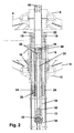
- Fig. 2 shows the longitudinal section through the stationary mast 12 and the drive elements.
- the driven by the hand crank 52 drive wheel 50 is anchored to the drive housing 38 in the stationary mast 12.
- the support web 30 serves as a support for the support profile 32, which provides with pulley bearing 28 and a toothed belt deflection pulley 36 rotating on a toothed belt deflection axis 48 for the required tension of the toothed belt 34.
- the deflection roller bearing 28 serves with its outer shape as a guide to the telescopic part, whereby the toothed belt 34 is centered in the telescopic tube 22.
- the lower linkage 10 is designed as a slide in opposite directions to the upper linkage ring 8.
- the slider cable 16 is guided by the displaceable lower linkage 10 via the slider cable deflection roller 18 rotating on the slide cable deflection axis to the slide cable attachment 24.
- the slide cable connection can be carried out on one side, mutually or multiply.
- the mast guide 14 and the telescopic guide 24 is used for good sliding properties of the telescopic tube 22.
- the drive wheel 50 with a locking device such as latching pawl or wrap spring brake.
- the support strut is connected to the upper linkage and the roof strut is connected to the lower linkage to form a funnel-shaped screen.
- the shield drive according to the in FIG. 8 illustrated embodiment is provided with a clamping device for the circulating organ.
- the screen drive according to the embodiment according to Fig. 8 allows operation on the fully assembled screen.
- the support profile 32 terminates with a wedge surface 54 which fills the support profile 32.
- By moving the clamping wedge 56 with the clamping or adjusting screw 62 the support profile is raised or lowered, thereby regulating the tension of the toothed belt 34.
- Support profile 32 and clamping wedge 56 are guided displaceably in the clamping housing 58.
- the clamping housing 58 is supported on the drive housing 38 or anchored separately on the stand mast 12.
- the clamping or adjusting screw 62 is actuated by a through hole in the stationary mast 12 with a conventional tool, namely a screwdriver.
Landscapes
- Walking Sticks, Umbrellas, And Fans (AREA)
- Transmission Devices (AREA)
- Power-Operated Mechanisms For Wings (AREA)
Description
- Die Erfindung betrifft einen Standschirm gemäss dem Oberbegriff von Anspruch 1.
- Antriebe für Schirme mit teleskopisch anheb- und absenkbarem, oberem Mastteil sind beispielweise aus der
DE 2 353 967 A bekannt. Dort wird vorgeschlagen, dass das Teleskopteil mit einem oberen Anlenkkranz über einen umlaufenden Zahnriemen angetrieben wird. Der Zahnriemen soll nach derDE 2 353 967 A beim Antriebsrad durch eine Öffnung aus dem Mast heraustreten und beim oberen Umlenkrad wieder am Teleskopteil angeschlossen werden. Das Lager der Umlenkrolle befindet sich in einem Mastausschnitt neben dem U-Profilförmigen Teleskops. Das Antriebsrad befindet sich in einer Mastöffnung. und nicht im geschlossenen Mast und das Umlauforgan zur Hälfte ausserhalb des Mastes. Die Spannvorrichtung ist ausserhalb des Mastes. - Nachteilig ist dabei, dass der offen liegende Zahnriemen ausserhalb des Mastes leicht beschädigt werden kann. Weiterhin hat es sich als störend erwiesen, dass er ästhetischen Anforderungen nicht genügen konnte. Zudem bewirken die Durchbrüche durch die Mastwand einen wesentlichen Festigkeitsverlust des Mastes als Ganzes. Weiterhin ist es nachteilig, dass die Antriebselemente keine in sich geschlossene Baugruppe ausbilden können, welche sich in den Mast einschieben lässt.
- In der
US-Patentschrift 4 424 824 A wird vorgeschlagen, anstelle eines Umlauforgans für die Betätigung des Teleskopteiles ein Winkelgetriebe für eine Spindel mit Spindelmutter im Teleskopteil zu verwenden. Damit ist zwar der Zahnriemen ersetzt und der Mastdurchbruch für die Antriebskurbel ist so klein, dass der Festigkeitsverlust des Mastes nicht mehr entscheidend ist. Die in derUS-Patentschrift 4 424 824 A vorgeschlagene Lösung ist aber in anderer Hinsicht sehr nachteilig, nämlich dass ein Winkelgetriebe notwendig ist und für notwendige Hublänge für das Öffnen und Schliessen des Schirmes viele Kurbelumdrehungen notwendig sind. - Aus der
NL 1 031 122 C2 NL 1 031 122 C2 - Die Aufgabe der Erfindung ist es, einen Antrieb vorzuschlagen, der mit wenigen Kurbelumdrehungen das Öffnen und Schliessen des Schirmes erlaubt und im Mastinneren geschützt liegt.
- Die Aufgabe der Erfindung wird durch einen Standschirm nach Anspruch 1 gelöst. Dabei haben die Massnahmen der Erfindung zur Folge, dass bei dem erfindungsgemässen Standschirm ein Mastdurchbruch - ausser bei der Handkurbel, wo der Durchbruch nicht stört - vermieden werden kann, dass aber trotzdem eine Handkurbel einen Umlauf antreibt und so mit wenig Kraftaufwand ein vorteilhaft übersetztes Anheben und Absenken des Teleskops ermöglicht.
- Vorteilhafte Ausgestaltungen sind in den Ansprüchen 2 bis 8 angegeben.
- In einer vorteilhaften Ausgestaltung der Erfindung ist die Umlenkstütze mittels eines Antriebsgehäuses mit dem Mast verbunden. Für die Montage und eine allfällige Revision ist es vorteilhaft, wenn das Umlenkrollenlager als Zentrierführung im Teleskoprohr ausgebildet ist. Auch vorteilhaft ist ein Stützensteg, auf welchem sich die Umlenkstütze abstützt.
- Die Erfindung erlaubt die Möglichkeit, den Standschirm ganz besonders vorteilhaft auszugestalten, indem die Umlenkstütze eine Spannvorrichtung für das Umlauforgan enthält, bevorzugt als Keilauflage ausgebildet und über eine Spannschraube von ausserhalb des Mastes betätigbar.
- Das Umlauforgan kann einen Zahnriemen oder eine Glied- oder Perlenkette aufweisen.
- Eine bevorzugte Ausgestaltung des Standschirmes weist ein Verbindungsorgan auf, vorzugsweise ein Seil, welches vom Teleskopteil über eine Umlenkrolle zum höhenverschiebbaren unteren Anlenkkranz geführt ist.
- Vorteilhaft ist es, wenn das Umlauforgan eine Abzweigung aufweist, welche über eine Umlenkrolle zum unteren Anlenkkranz geführt ist.
- Die vorbenannten sowie die beanspruchten und in den nachfolgenden Ausführungsbeispielen beschriebenen, erfindungsgemäss zu verwendenden Elemente unterliegen in ihrer Grösse, Formgestaltung, Materialverwendung und ihrer technischen Konzeption keinen besonderen Ausnahmebedingungen, so dass die in dem jeweiligen Anwendungsgebiet bekannten Auswahlkriterien uneingeschränkt Anwendung finden können.
- Weitere Einzelheiten, Vorteile und Merkmale des Gegenstandes der vorliegenden Erfindung ergeben sich aus der nachfolgenden Beschreibung der dazu gehörenden Zeichnungen, in denen - beispielhaft - erfindungsgemässe Standschirme erläutert werden. In den Zeichnungen zeigt:
- Figur 1
- Einen Standschirm gemäss einem Ausführungsbeispiel der vorliegenden Erfindung, als Gesamtdarstellung;
- Figur 2
- einen Längsschnitt durch den Mast und die Antriebselemente zu dem Standschirm gemäss
Figur 1 ; - Figur 3
- eine Explosionsdarstellung des Teleskoprohres mit den Funktionselementen zu dem Standschirm gemäss
Figur 1 . - Figur 4
- eine Situationsdarstellung zur Erläuterung der Schnitte I-I, H-H und L-L, gemäss dem Ausführungsbeispiel nach
Figur 2 , - Figur 5
- eine Querschnittsdarstellung entlang der Linie I-I auf der Höhe der Zahnriemen-Umlenkrolle, gemäss
Figur 4 , - Figur 6
- eine Querschnittsdarstellung entlang der Linie H-H auf der Höhe der Zahnplatte, gemäss
Figur 4 . - Figur 7
- eine Querschnittsdarstellung entlang der Linie L-L durch das Antriebsrad, gemäss
Figur 4 ; und - Fig. 8
- eine Spannvorrichtung für das Umlauforgan.
- Der in
Figur 1 als ganzes mit 2 bezeichnete Schirm mit dem Standmast 12 ist der Einfachheit halber nur mit zwei sich gegenüberliegende Dachstreben 4 und Stützstreben 6 an den oberen Anlenkkranz 8 und den unteren Anlenkkranz 10 angelenkt dargestellt. Bei der Ausführung der Erfindung richtet sich die Anzahl der Streben nach Grösse und Schirmform und kann von 6 bis über 16 reichen. Im Standmast 12 befindet sich die Antriebseinheit, welche durch die Handkurbel 52 betätigt werden kann, um den Standschirm durch Absenken oder Anheben des Teleskoprohres 22 zu öffnen oder zu schliessen. Das Teleskoprohr ist oben mittels eines Teleskoprohrstopfens 40 verschlossen. -
Fig. 2 zeigt den Längsschnitt durch den Standmast 12 und die Antriebselemente. Das mit der Handkurbel 52 betätigte Antriebsrad 50 ist mit dem Antriebsgehäuse 38 im Standmast 12 verankert. Der Stützensteg 30 dient als Auflage für das Stützprofil 32, welches mit Umlenkrollenlager 28 und einer auf einer Zahnriemen-Umlenkachse 48 rotierenden Zahnriemen-Umlenkrolle 36 für die erforderliche Spannung des Zahnriemens 34 sorgt. Das Umlenkrollenlager 28 dient mit seiner äusseren Form auch als Führung zum Teleskopteil, womit der Zahnriemen 34 im Teleskoprohr 22 zentriert bleibt. Mit der gezahnten Platte 26 und der Teleskopführung 24 werden einerseits die Enden des Zahnriemens 34 zusammengehalten und andererseits mit den Führungsplattenschrauben 46 und - Muttern 44 mit dem Teleskoprohr 22 verbunden. - Um die Geometrie von Dach- und Stützstreben 4, 6 zu verbessern, ist im dargestellten Ausführungsbeispiel der untere Anlenkkranz 10 als Schieber gegenläufig zum oberen Anlenkkranz 8 ausgelegt. Das Schieberseil 16 wird vom verschiebbaren unteren Anlenkkranz 10 über die auf der Schieberseil-Umlenkachse rotierenden Schieberseil-Umlenkrolle 18 zur Schieberseilbefestigung 24 geführt. Die Schieberseilverbindung kann einseitig, gegenseitig oder mehrfach ausgeführt werden. Für gute Gleiteigenschaften des Teleskoprohres 22 dient die Mastführung 14 und die Teleskopführung 24.
- Im hier dargestellten Ausführungsbeispiel ist das Antriebsrad 50 mit einer Arretiervorrichtung wie Einrastklinke oder Schlingfederbremse.
- Alternativ ist die Stützstrebe an den oberen Anlenkkranz und die Dachstrebe an den unteren Anlenkkranz angeschlossen, um einen trichterförmigen Schirm zu bilden.
- Der Schirmantrieb gemäss dem in
Figur 8 dargestellten Ausführungsbeispiel ist mit einer Spannvorrichtung für das Umlauforgan versehen. Der Schirmantrieb gemäss dem Ausführungsbeispiel nachFig. 8 erlaubt eine Betätigung am fertig montierten Schirm. Das Stützprofil 32 endet mit einer Keilfläche 54, welche das Stützprofil 32 ausfüllt. Durch Verschieben des Spannkeils 56 mit der Spann- bzw. Stellschraube 62 wird das Stützprofil angehoben oder abgesenkt und dadurch die Spannung des Zahnriemens 34 reguliert. Stützprofil 32 und Spannkeil 56 sind im Spanngehäuse 58 verschiebbar geführt. Das Spanngehäuse 58 ist auf das Antriebsgehäuse 38 abgestützt oder separat am Standmast 12 verankert. Die Spann- bzw. Stellschraube 62 wird durch ein Durchgangsloch im Standmast 12 mit einem herkömmlichen Werkzeug, nämlich einem Schraubendreher betätigt. -
- 2
- Standschirm
- 4
- Dachstreben
- 6
- Stützstreben
- 8
- oberer Anlenkkranz
- 10
- unterer Anlenkkranz
- 12
- Mast, Standmast
- 14
- Mastführung
- 16
- Schieberseil
- 18
- Schieberseil-Umlenkrolle
- 22
- Teleskoprohr
- 24
- Teleskopführung und Schieberseilbefestigung
- 26
- gezahnte Platte
- 28
- Umlenkrollenlager und Zentrierführung
- 30
- Stützensteg
- 32
- Umlenkstütze, Stützprofil
- 34
- Zahnriemen
- 36
- Zahnriemen-Umlenkrolle
- 38
- Antriebsgehäuse
- 40
- Teleskoprohrstopfen
- 44
- Muttern für Führungsplatten-Schrauben
- 46
- Führungsplattenschrauben
- 48
- Zahnriemen-Umlenkachse
- 50
- Antriebsrad
- 52
- Antriebskurbel/Handkurbel
- 54
- Keilfläche der Umlenkstütze
- 56
- Spannkeil
- 58
- Spanngehäuse
- 62
- Spannschraube, Stellschraube
Claims (8)
- Standschirm (2) mit einem Mast (12) und einem faltbaren Schirmdach mit Dach- und Stützstreben (4, 6) und mit einem unteren Anlenkkranz (10) und mit einem oberen Anlenkkranz (8), wobei die Dachstreben (4) und die Stützstreben (6) jeweils mit dem unteren Anlenkkranz (10) oder mit dem oberen Anlenkkranz (8) verbunden sind, wobei der obere Anlenkkranz (8) mit einem im Mast (12) geführten, anhebbaren und absenkbaren Teleskoprohr (22) verbunden ist und wobei das Teleskoprohr (22) zum Anheben und Absenken mit einem Umlauforgan (34) verbunden ist, welches über eine obere Umlenkrolle (36) und ein im Mast (12) angeordnetes Antriebsrad (50) betätigbar ist, wobei die obere Umlenkrolle (36) mittels eines Umlenkrollenlagers (28) an einer Umlenkstütze (32) angeordnet ist, wobei die Umlenkstütze (32) am Mast (12) befestigt ist und in das Teleskoprohr (22) hinein ragt, wobei die Umlenkstütze (32) mittels eines Antriebsgehäuses (38) im Mast angeordnet und mit dem Mast (12) verbunden ist und wobei das Umlauforgan (34) einen Zahnriemen oder eine Glied- oder Perlenkette aufweist.
- Standschirm nach Anspruch 1, wobei das Umlenkrollenlager (28) als Zentrierführung im Teleskoprohr (22) ausgebildet ist
- Standschirm nach Anspruch 1, wobei der Standsehirm weiterhin einen Stützensteg (30) aufweist, welcher den unteren Teil der Umlenkstütze (32) unterstützt.
- Standschirm nach Anspruch 1, wobei die Umlenkstütze (32) eine Spannvorrichtung (54) für das Umlauforgan (34) enthält.
- Standschirm nach Anspruch 4, wobei die Spannvorrichtung (54) als Keilauflage ausgebildet ist.
- Standschirm nach einem der Ansprüche 4 oder 5, wobei die Spannvorrichtung über eine Spannschraube (62) von ausserhalb des Mastes (12) betätigbar ist.
- Standschirm nach Anspruch 1, wobei der Standschirm weiterhin ein Verbindungsorgan, vorzugsweise ein Seil (16), aufweist, welches vom Teleskoprohr (22) über eine Umlenkrolle (18) zum höhenverschiebbaren unteren Anlenkkranz (10) geführt ist.
- Standschirm nach Anspruch 1, wobei das Umlauforgan (34) eine Abzweigung aufweist, welche über eine Umlenkrolle (18) zum unteren Anlenkkranz (10) geführt ist.
Priority Applications (3)
| Application Number | Priority Date | Filing Date | Title |
|---|---|---|---|
| EP10166397A EP2397044B1 (de) | 2010-06-17 | 2010-06-17 | Standschirm |
| US13/161,708 US8684017B2 (en) | 2010-06-17 | 2011-06-16 | Standing parasol |
| CN2011202047235U CN202190860U (zh) | 2010-06-17 | 2011-06-17 | 固定式伞 |
Applications Claiming Priority (1)
| Application Number | Priority Date | Filing Date | Title |
|---|---|---|---|
| EP10166397A EP2397044B1 (de) | 2010-06-17 | 2010-06-17 | Standschirm |
Publications (2)
| Publication Number | Publication Date |
|---|---|
| EP2397044A1 EP2397044A1 (de) | 2011-12-21 |
| EP2397044B1 true EP2397044B1 (de) | 2012-10-24 |
Family
ID=42797478
Family Applications (1)
| Application Number | Title | Priority Date | Filing Date |
|---|---|---|---|
| EP10166397A Active EP2397044B1 (de) | 2010-06-17 | 2010-06-17 | Standschirm |
Country Status (3)
| Country | Link |
|---|---|
| US (1) | US8684017B2 (de) |
| EP (1) | EP2397044B1 (de) |
| CN (1) | CN202190860U (de) |
Cited By (1)
| Publication number | Priority date | Publication date | Assignee | Title |
|---|---|---|---|---|
| EP4670562A1 (de) | 2024-06-25 | 2025-12-31 | Glatz AG | Standschirm |
Families Citing this family (2)
| Publication number | Priority date | Publication date | Assignee | Title |
|---|---|---|---|---|
| US8757183B2 (en) * | 2012-10-05 | 2014-06-24 | Dee Volin | Solar-powered pulley-assisted umbrella having simultaneously and oppositely movable top-and-bottom weighted brackets |
| US9591903B1 (en) * | 2016-02-18 | 2017-03-14 | Ai-Hui Huang | Electric umbrella having roller sets |
Family Cites Families (7)
| Publication number | Priority date | Publication date | Assignee | Title |
|---|---|---|---|---|
| US3282275A (en) * | 1965-02-12 | 1966-11-01 | Pearlstine Morton | Beach umbrella |
| CH543253A (de) * | 1972-11-02 | 1973-10-31 | Glatz Ag | Schirm, insbesondere Gartenschirm |
| US4424824A (en) | 1982-07-20 | 1984-01-10 | Becher Textil- Und Stahlbau Gmbh | Garden and market umbrella |
| US5785069A (en) * | 1994-03-03 | 1998-07-28 | Glatz Ag | Standing umbrella |
| US6058951A (en) * | 1998-07-28 | 2000-05-09 | Wilson; Robert Joe | Remotely controlled and electrically operated umbrellas |
| NL1031122C2 (nl) * | 2006-02-10 | 2007-08-13 | Hydrosense Technology Europ B | Inklapbare schermconstructie. |
| US8272391B2 (en) * | 2009-11-30 | 2012-09-25 | Luo Xiong | Auto bending structure of sunshade |
-
2010
- 2010-06-17 EP EP10166397A patent/EP2397044B1/de active Active
-
2011
- 2011-06-16 US US13/161,708 patent/US8684017B2/en active Active
- 2011-06-17 CN CN2011202047235U patent/CN202190860U/zh not_active Expired - Lifetime
Cited By (1)
| Publication number | Priority date | Publication date | Assignee | Title |
|---|---|---|---|---|
| EP4670562A1 (de) | 2024-06-25 | 2025-12-31 | Glatz AG | Standschirm |
Also Published As
| Publication number | Publication date |
|---|---|
| CN202190860U (zh) | 2012-04-18 |
| EP2397044A1 (de) | 2011-12-21 |
| US20110315179A1 (en) | 2011-12-29 |
| US8684017B2 (en) | 2014-04-01 |
Similar Documents
| Publication | Publication Date | Title |
|---|---|---|
| DE4106221C1 (de) | ||
| DE102007021803B4 (de) | Teleskopierbarer Schirm | |
| EP2842446A1 (de) | Schwenkbarer Sonnenschirm | |
| DE8915268U1 (de) | Vorrichtung zum Öffnen und Schließen von Sonnenschirmen | |
| DE19604599C1 (de) | Standschirm | |
| EP2397044B1 (de) | Standschirm | |
| EP3738462A1 (de) | Freiarm-standschirm, insbesondere für sonnen- und regenschutz | |
| DE4105482A1 (de) | Schwenktuere fuer kundenfuehrungsanlagen | |
| DE2353967C3 (de) | Schirm, insbesondere Gartenschirm | |
| EP1214489B1 (de) | Wetterschutzvorrichtung mit wenigstens einem faltbaren schutzelement | |
| DE102004007126A1 (de) | Vorrichtung zum motorischen Öffnen und Schließen eines Karosserieteils | |
| EP3659685B1 (de) | Sandkastensystem | |
| DE1272771B (de) | Handbetaetigter Fensterheber fuer in den Fensterschacht eines Kraftfahrzeugs versenkbare Schiebefenster | |
| DE2943846A1 (de) | Gewichtsausgleichsvorrichtung | |
| CH695657A5 (de) | Trichterschirm. | |
| DE102017105606B4 (de) | Sonnenschirm | |
| DE102017009101A1 (de) | Sonnenschirm | |
| DE102009006519B4 (de) | Pagodenschirm | |
| DE810316C (de) | Markisenaehnlicher Sonnenschutz | |
| EP0439027B1 (de) | Einrichtung an einem Rolladen | |
| DE2113534C3 (de) | Hallenartige, ein- und ausfahrbare Überdachung, insbesondere für Schwimmbäder oder Sportplätze | |
| EP4188149A1 (de) | Höhenverstellbarer mast und/oder auslegearm | |
| DE20108269U1 (de) | Schirmöffnungsvorrichtung für den Einbau in einen Sonnenschirm | |
| DE20313473U1 (de) | Schirm, insbesondere Sonnenschirm, mit auf einem Standrohr angebrachtem Spanngestell für eine Bespannung | |
| DE29824529U1 (de) | Hubvorrichtung vorzugsweise für die Höhenverstellung eines Kranken- oder Pflegebetts |
Legal Events
| Date | Code | Title | Description |
|---|---|---|---|
| AK | Designated contracting states |
Kind code of ref document: A1 Designated state(s): AL AT BE BG CH CY CZ DE DK EE ES FI FR GB GR HR HU IE IS IT LI LT LU LV MC MK MT NL NO PL PT RO SE SI SK SM TR |
|
| AX | Request for extension of the european patent |
Extension state: BA ME RS |
|
| PUAI | Public reference made under article 153(3) epc to a published international application that has entered the european phase |
Free format text: ORIGINAL CODE: 0009012 |
|
| 17P | Request for examination filed |
Effective date: 20120427 |
|
| GRAP | Despatch of communication of intention to grant a patent |
Free format text: ORIGINAL CODE: EPIDOSNIGR1 |
|
| GRAS | Grant fee paid |
Free format text: ORIGINAL CODE: EPIDOSNIGR3 |
|
| GRAA | (expected) grant |
Free format text: ORIGINAL CODE: 0009210 |
|
| AK | Designated contracting states |
Kind code of ref document: B1 Designated state(s): AL AT BE BG CH CY CZ DE DK EE ES FI FR GB GR HR HU IE IS IT LI LT LU LV MC MK MT NL NO PL PT RO SE SI SK SM TR |
|
| REG | Reference to a national code |
Ref country code: GB Ref legal event code: FG4D Free format text: NOT ENGLISH |
|
| REG | Reference to a national code |
Ref country code: CH Ref legal event code: NV Representative=s name: SCHMAUDER & PARTNER AG PATENT- UND MARKENANWAELTE Ref country code: CH Ref legal event code: EP |
|
| REG | Reference to a national code |
Ref country code: AT Ref legal event code: REF Ref document number: 580421 Country of ref document: AT Kind code of ref document: T Effective date: 20121115 |
|
| REG | Reference to a national code |
Ref country code: IE Ref legal event code: FG4D Free format text: LANGUAGE OF EP DOCUMENT: GERMAN |
|
| REG | Reference to a national code |
Ref country code: DE Ref legal event code: R096 Ref document number: 502010001485 Country of ref document: DE Effective date: 20121227 |
|
| REG | Reference to a national code |
Ref country code: NL Ref legal event code: T3 |
|
| PG25 | Lapsed in a contracting state [announced via postgrant information from national office to epo] |
Ref country code: FI Free format text: LAPSE BECAUSE OF FAILURE TO SUBMIT A TRANSLATION OF THE DESCRIPTION OR TO PAY THE FEE WITHIN THE PRESCRIBED TIME-LIMIT Effective date: 20121024 Ref country code: HR Free format text: LAPSE BECAUSE OF FAILURE TO SUBMIT A TRANSLATION OF THE DESCRIPTION OR TO PAY THE FEE WITHIN THE PRESCRIBED TIME-LIMIT Effective date: 20121024 Ref country code: NO Free format text: LAPSE BECAUSE OF FAILURE TO SUBMIT A TRANSLATION OF THE DESCRIPTION OR TO PAY THE FEE WITHIN THE PRESCRIBED TIME-LIMIT Effective date: 20130124 Ref country code: SE Free format text: LAPSE BECAUSE OF FAILURE TO SUBMIT A TRANSLATION OF THE DESCRIPTION OR TO PAY THE FEE WITHIN THE PRESCRIBED TIME-LIMIT Effective date: 20121024 Ref country code: IS Free format text: LAPSE BECAUSE OF FAILURE TO SUBMIT A TRANSLATION OF THE DESCRIPTION OR TO PAY THE FEE WITHIN THE PRESCRIBED TIME-LIMIT Effective date: 20130224 |
|
| PG25 | Lapsed in a contracting state [announced via postgrant information from national office to epo] |
Ref country code: PL Free format text: LAPSE BECAUSE OF FAILURE TO SUBMIT A TRANSLATION OF THE DESCRIPTION OR TO PAY THE FEE WITHIN THE PRESCRIBED TIME-LIMIT Effective date: 20121024 Ref country code: LV Free format text: LAPSE BECAUSE OF FAILURE TO SUBMIT A TRANSLATION OF THE DESCRIPTION OR TO PAY THE FEE WITHIN THE PRESCRIBED TIME-LIMIT Effective date: 20121024 Ref country code: GR Free format text: LAPSE BECAUSE OF FAILURE TO SUBMIT A TRANSLATION OF THE DESCRIPTION OR TO PAY THE FEE WITHIN THE PRESCRIBED TIME-LIMIT Effective date: 20130125 Ref country code: SI Free format text: LAPSE BECAUSE OF FAILURE TO SUBMIT A TRANSLATION OF THE DESCRIPTION OR TO PAY THE FEE WITHIN THE PRESCRIBED TIME-LIMIT Effective date: 20121024 Ref country code: PT Free format text: LAPSE BECAUSE OF FAILURE TO SUBMIT A TRANSLATION OF THE DESCRIPTION OR TO PAY THE FEE WITHIN THE PRESCRIBED TIME-LIMIT Effective date: 20130225 |
|
| PG25 | Lapsed in a contracting state [announced via postgrant information from national office to epo] |
Ref country code: DK Free format text: LAPSE BECAUSE OF FAILURE TO SUBMIT A TRANSLATION OF THE DESCRIPTION OR TO PAY THE FEE WITHIN THE PRESCRIBED TIME-LIMIT Effective date: 20121024 Ref country code: CZ Free format text: LAPSE BECAUSE OF FAILURE TO SUBMIT A TRANSLATION OF THE DESCRIPTION OR TO PAY THE FEE WITHIN THE PRESCRIBED TIME-LIMIT Effective date: 20121024 Ref country code: BG Free format text: LAPSE BECAUSE OF FAILURE TO SUBMIT A TRANSLATION OF THE DESCRIPTION OR TO PAY THE FEE WITHIN THE PRESCRIBED TIME-LIMIT Effective date: 20130124 Ref country code: EE Free format text: LAPSE BECAUSE OF FAILURE TO SUBMIT A TRANSLATION OF THE DESCRIPTION OR TO PAY THE FEE WITHIN THE PRESCRIBED TIME-LIMIT Effective date: 20121024 Ref country code: SK Free format text: LAPSE BECAUSE OF FAILURE TO SUBMIT A TRANSLATION OF THE DESCRIPTION OR TO PAY THE FEE WITHIN THE PRESCRIBED TIME-LIMIT Effective date: 20121024 |
|
| PG25 | Lapsed in a contracting state [announced via postgrant information from national office to epo] |
Ref country code: RO Free format text: LAPSE BECAUSE OF FAILURE TO SUBMIT A TRANSLATION OF THE DESCRIPTION OR TO PAY THE FEE WITHIN THE PRESCRIBED TIME-LIMIT Effective date: 20121024 |
|
| PLBE | No opposition filed within time limit |
Free format text: ORIGINAL CODE: 0009261 |
|
| STAA | Information on the status of an ep patent application or granted ep patent |
Free format text: STATUS: NO OPPOSITION FILED WITHIN TIME LIMIT |
|
| 26N | No opposition filed |
Effective date: 20130725 |
|
| PG25 | Lapsed in a contracting state [announced via postgrant information from national office to epo] |
Ref country code: ES Free format text: LAPSE BECAUSE OF FAILURE TO SUBMIT A TRANSLATION OF THE DESCRIPTION OR TO PAY THE FEE WITHIN THE PRESCRIBED TIME-LIMIT Effective date: 20130204 |
|
| REG | Reference to a national code |
Ref country code: DE Ref legal event code: R097 Ref document number: 502010001485 Country of ref document: DE Effective date: 20130725 |
|
| PG25 | Lapsed in a contracting state [announced via postgrant information from national office to epo] |
Ref country code: CY Free format text: LAPSE BECAUSE OF FAILURE TO SUBMIT A TRANSLATION OF THE DESCRIPTION OR TO PAY THE FEE WITHIN THE PRESCRIBED TIME-LIMIT Effective date: 20121024 |
|
| BERE | Be: lapsed |
Owner name: GLATZ A.G. Effective date: 20130630 |
|
| PG25 | Lapsed in a contracting state [announced via postgrant information from national office to epo] |
Ref country code: MC Free format text: LAPSE BECAUSE OF FAILURE TO SUBMIT A TRANSLATION OF THE DESCRIPTION OR TO PAY THE FEE WITHIN THE PRESCRIBED TIME-LIMIT Effective date: 20121024 |
|
| REG | Reference to a national code |
Ref country code: IE Ref legal event code: MM4A |
|
| PG25 | Lapsed in a contracting state [announced via postgrant information from national office to epo] |
Ref country code: BE Free format text: LAPSE BECAUSE OF NON-PAYMENT OF DUE FEES Effective date: 20130630 |
|
| PG25 | Lapsed in a contracting state [announced via postgrant information from national office to epo] |
Ref country code: IE Free format text: LAPSE BECAUSE OF NON-PAYMENT OF DUE FEES Effective date: 20130617 |
|
| PG25 | Lapsed in a contracting state [announced via postgrant information from national office to epo] |
Ref country code: LT Free format text: LAPSE BECAUSE OF FAILURE TO SUBMIT A TRANSLATION OF THE DESCRIPTION OR TO PAY THE FEE WITHIN THE PRESCRIBED TIME-LIMIT Effective date: 20121024 |
|
| GBPC | Gb: european patent ceased through non-payment of renewal fee |
Effective date: 20140617 |
|
| PG25 | Lapsed in a contracting state [announced via postgrant information from national office to epo] |
Ref country code: MT Free format text: LAPSE BECAUSE OF FAILURE TO SUBMIT A TRANSLATION OF THE DESCRIPTION OR TO PAY THE FEE WITHIN THE PRESCRIBED TIME-LIMIT Effective date: 20121024 |
|
| PG25 | Lapsed in a contracting state [announced via postgrant information from national office to epo] |
Ref country code: GB Free format text: LAPSE BECAUSE OF NON-PAYMENT OF DUE FEES Effective date: 20140617 Ref country code: SM Free format text: LAPSE BECAUSE OF FAILURE TO SUBMIT A TRANSLATION OF THE DESCRIPTION OR TO PAY THE FEE WITHIN THE PRESCRIBED TIME-LIMIT Effective date: 20121024 |
|
| PG25 | Lapsed in a contracting state [announced via postgrant information from national office to epo] |
Ref country code: TR Free format text: LAPSE BECAUSE OF FAILURE TO SUBMIT A TRANSLATION OF THE DESCRIPTION OR TO PAY THE FEE WITHIN THE PRESCRIBED TIME-LIMIT Effective date: 20121024 |
|
| PG25 | Lapsed in a contracting state [announced via postgrant information from national office to epo] |
Ref country code: LU Free format text: LAPSE BECAUSE OF NON-PAYMENT OF DUE FEES Effective date: 20130617 Ref country code: HU Free format text: LAPSE BECAUSE OF FAILURE TO SUBMIT A TRANSLATION OF THE DESCRIPTION OR TO PAY THE FEE WITHIN THE PRESCRIBED TIME-LIMIT; INVALID AB INITIO Effective date: 20100617 Ref country code: MK Free format text: LAPSE BECAUSE OF FAILURE TO SUBMIT A TRANSLATION OF THE DESCRIPTION OR TO PAY THE FEE WITHIN THE PRESCRIBED TIME-LIMIT Effective date: 20121024 |
|
| REG | Reference to a national code |
Ref country code: FR Ref legal event code: PLFP Year of fee payment: 7 |
|
| REG | Reference to a national code |
Ref country code: FR Ref legal event code: PLFP Year of fee payment: 8 |
|
| REG | Reference to a national code |
Ref country code: FR Ref legal event code: PLFP Year of fee payment: 9 |
|
| PG25 | Lapsed in a contracting state [announced via postgrant information from national office to epo] |
Ref country code: AL Free format text: LAPSE BECAUSE OF FAILURE TO SUBMIT A TRANSLATION OF THE DESCRIPTION OR TO PAY THE FEE WITHIN THE PRESCRIBED TIME-LIMIT Effective date: 20121024 |
|
| PGFP | Annual fee paid to national office [announced via postgrant information from national office to epo] |
Ref country code: DE Payment date: 20250618 Year of fee payment: 16 |
|
| PGFP | Annual fee paid to national office [announced via postgrant information from national office to epo] |
Ref country code: NL Payment date: 20250618 Year of fee payment: 16 |
|
| PGFP | Annual fee paid to national office [announced via postgrant information from national office to epo] |
Ref country code: FR Payment date: 20250624 Year of fee payment: 16 |
|
| PGFP | Annual fee paid to national office [announced via postgrant information from national office to epo] |
Ref country code: AT Payment date: 20250620 Year of fee payment: 16 |
|
| PGFP | Annual fee paid to national office [announced via postgrant information from national office to epo] |
Ref country code: IT Payment date: 20250624 Year of fee payment: 16 |
|
| PGFP | Annual fee paid to national office [announced via postgrant information from national office to epo] |
Ref country code: CH Payment date: 20250701 Year of fee payment: 16 |