EP2394932B1 - Capsule à zone d'amorce de rupture - Google Patents
Capsule à zone d'amorce de rupture Download PDFInfo
- Publication number
- EP2394932B1 EP2394932B1 EP10306436.6A EP10306436A EP2394932B1 EP 2394932 B1 EP2394932 B1 EP 2394932B1 EP 10306436 A EP10306436 A EP 10306436A EP 2394932 B1 EP2394932 B1 EP 2394932B1
- Authority
- EP
- European Patent Office
- Prior art keywords
- capsule
- membrane
- annular
- central region
- resistance
- Prior art date
- Legal status (The legal status is an assumption and is not a legal conclusion. Google has not performed a legal analysis and makes no representation as to the accuracy of the status listed.)
- Active
Links
- 239000002775 capsule Substances 0.000 title claims description 139
- 239000012528 membrane Substances 0.000 claims description 57
- 238000000605 extraction Methods 0.000 claims description 52
- 239000000463 material Substances 0.000 claims description 45
- 239000000126 substance Substances 0.000 claims description 31
- 239000004033 plastic Substances 0.000 claims description 26
- 229920003023 plastic Polymers 0.000 claims description 26
- 239000007788 liquid Substances 0.000 claims description 22
- 230000002093 peripheral effect Effects 0.000 claims description 20
- 235000013361 beverage Nutrition 0.000 claims description 11
- IJGRMHOSHXDMSA-UHFFFAOYSA-N Atomic nitrogen Chemical compound N#N IJGRMHOSHXDMSA-UHFFFAOYSA-N 0.000 claims description 7
- 238000002360 preparation method Methods 0.000 claims description 4
- 229910052757 nitrogen Inorganic materials 0.000 claims description 3
- 230000002787 reinforcement Effects 0.000 claims 1
- 239000012530 fluid Substances 0.000 description 16
- 208000031968 Cadaver Diseases 0.000 description 14
- 230000000694 effects Effects 0.000 description 13
- 238000007789 sealing Methods 0.000 description 5
- 230000003014 reinforcing effect Effects 0.000 description 4
- 238000002955 isolation Methods 0.000 description 3
- 238000004519 manufacturing process Methods 0.000 description 3
- 239000004952 Polyamide Substances 0.000 description 2
- 229910052782 aluminium Inorganic materials 0.000 description 2
- XAGFODPZIPBFFR-UHFFFAOYSA-N aluminium Chemical compound [Al] XAGFODPZIPBFFR-UHFFFAOYSA-N 0.000 description 2
- 238000004040 coloring Methods 0.000 description 2
- 230000006835 compression Effects 0.000 description 2
- 238000007906 compression Methods 0.000 description 2
- 238000002347 injection Methods 0.000 description 2
- 239000007924 injection Substances 0.000 description 2
- 230000005012 migration Effects 0.000 description 2
- 238000013508 migration Methods 0.000 description 2
- 230000003647 oxidation Effects 0.000 description 2
- 238000007254 oxidation reaction Methods 0.000 description 2
- 239000002985 plastic film Substances 0.000 description 2
- 229920006255 plastic film Polymers 0.000 description 2
- 229920002647 polyamide Polymers 0.000 description 2
- 231100000701 toxic element Toxicity 0.000 description 2
- XLYOFNOQVPJJNP-UHFFFAOYSA-N water Substances O XLYOFNOQVPJJNP-UHFFFAOYSA-N 0.000 description 2
- 239000004411 aluminium Substances 0.000 description 1
- 230000004323 axial length Effects 0.000 description 1
- 230000004888 barrier function Effects 0.000 description 1
- 230000009286 beneficial effect Effects 0.000 description 1
- 230000015556 catabolic process Effects 0.000 description 1
- 239000012141 concentrate Substances 0.000 description 1
- 238000006731 degradation reaction Methods 0.000 description 1
- 238000009792 diffusion process Methods 0.000 description 1
- 239000000839 emulsion Substances 0.000 description 1
- 235000013305 food Nutrition 0.000 description 1
- 238000007373 indentation Methods 0.000 description 1
- 239000011261 inert gas Substances 0.000 description 1
- 230000014759 maintenance of location Effects 0.000 description 1
- 229910052751 metal Inorganic materials 0.000 description 1
- 239000002184 metal Substances 0.000 description 1
- 239000000049 pigment Substances 0.000 description 1
- 229920002635 polyurethane Polymers 0.000 description 1
- 239000004814 polyurethane Substances 0.000 description 1
- 238000003825 pressing Methods 0.000 description 1
- 238000007665 sagging Methods 0.000 description 1
- 230000003313 weakening effect Effects 0.000 description 1
Images


Classifications
-
- A—HUMAN NECESSITIES
- A47—FURNITURE; DOMESTIC ARTICLES OR APPLIANCES; COFFEE MILLS; SPICE MILLS; SUCTION CLEANERS IN GENERAL
- A47J—KITCHEN EQUIPMENT; COFFEE MILLS; SPICE MILLS; APPARATUS FOR MAKING BEVERAGES
- A47J31/00—Apparatus for making beverages
- A47J31/24—Coffee-making apparatus in which hot water is passed through the filter under pressure, i.e. in which the coffee grounds are extracted under pressure
- A47J31/34—Coffee-making apparatus in which hot water is passed through the filter under pressure, i.e. in which the coffee grounds are extracted under pressure with hot water under liquid pressure
- A47J31/36—Coffee-making apparatus in which hot water is passed through the filter under pressure, i.e. in which the coffee grounds are extracted under pressure with hot water under liquid pressure with mechanical pressure-producing means
- A47J31/3604—Coffee-making apparatus in which hot water is passed through the filter under pressure, i.e. in which the coffee grounds are extracted under pressure with hot water under liquid pressure with mechanical pressure-producing means with a mechanism arranged to move the brewing chamber between loading, infusing and ejecting stations
- A47J31/3623—Cartridges being employed
-
- B—PERFORMING OPERATIONS; TRANSPORTING
- B65—CONVEYING; PACKING; STORING; HANDLING THIN OR FILAMENTARY MATERIAL
- B65D—CONTAINERS FOR STORAGE OR TRANSPORT OF ARTICLES OR MATERIALS, e.g. BAGS, BARRELS, BOTTLES, BOXES, CANS, CARTONS, CRATES, DRUMS, JARS, TANKS, HOPPERS, FORWARDING CONTAINERS; ACCESSORIES, CLOSURES, OR FITTINGS THEREFOR; PACKAGING ELEMENTS; PACKAGES
- B65D85/00—Containers, packaging elements or packages, specially adapted for particular articles or materials
- B65D85/70—Containers, packaging elements or packages, specially adapted for particular articles or materials for materials not otherwise provided for
- B65D85/804—Disposable containers or packages with contents which are mixed, infused or dissolved in situ, i.e. without having been previously removed from the package
- B65D85/8043—Packages adapted to allow liquid to pass through the contents
- B65D85/8049—Details of the inlet
-
- B—PERFORMING OPERATIONS; TRANSPORTING
- B65—CONVEYING; PACKING; STORING; HANDLING THIN OR FILAMENTARY MATERIAL
- B65D—CONTAINERS FOR STORAGE OR TRANSPORT OF ARTICLES OR MATERIALS, e.g. BAGS, BARRELS, BOTTLES, BOXES, CANS, CARTONS, CRATES, DRUMS, JARS, TANKS, HOPPERS, FORWARDING CONTAINERS; ACCESSORIES, CLOSURES, OR FITTINGS THEREFOR; PACKAGING ELEMENTS; PACKAGES
- B65D85/00—Containers, packaging elements or packages, specially adapted for particular articles or materials
- B65D85/70—Containers, packaging elements or packages, specially adapted for particular articles or materials for materials not otherwise provided for
- B65D85/804—Disposable containers or packages with contents which are mixed, infused or dissolved in situ, i.e. without having been previously removed from the package
- B65D85/8043—Packages adapted to allow liquid to pass through the contents
- B65D85/8061—Filters
Definitions
- the present invention relates to a capsule for extracting a pressurized beverage, of the type comprising a cup-shaped body and a lid defining together a chamber containing a substance for the preparation of a beverage, the body comprising a side wall substantially frusto-conical outer surface and a bottom formed integrally with the side wall and closing the outer side wall at a rear end of the body, the cap sealing the outer side wall at the front end of the body, the capsule being adapted to be disposed in an extraction device so that a pressurized extraction liquid enters the capsule from the bottom and so through the seal.
- FR 2,373,999 discloses such a capsule for use in a beverage extraction device to produce a beverage such as coffee.
- An object of the invention is to provide a capsule to limit the risk of sagging while allowing the extraction of a drink.
- Other objects of the invention are to provide a capsule that can be easily calibrated so as to adjust the pressure level at which the extraction liquid enters the capsule, to propose a reduced cost capsule, and to provide a compatible capsule. with many beverage extraction devices.
- a first aspect of the invention relates to a capsule according to the subject of claim 1.
- a second aspect of the invention relates to a system comprising a capsule according to the invention, and an extraction device comprising a housing for receiving the capsule, a support and an extraction liquid supply duct.
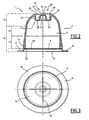
- the capsule 1 according to a first embodiment of the invention, represented on the Figures 1 to 3 , comprises a hollow body 4 and an outlet cap 6 defining together an inner chamber 8 containing a substance (not shown) for the preparation of a beverage.
- the body 4 has a general cup shape and comprises a side wall 10, a bottom 12 closing a closed rear end 20 of the body 4, and an annular flange 16 surrounding an open front end 22 of the body 4.
- the body 4 is made in one piece.
- the side wall 10, the bottom 12 and the annular flange 16 are integral.
- the body 4 is made of an airtight material and water in a plastic material or derived from plastic.
- the side wall 10 extends from the bottom 12 along a longitudinal axis X to the front end 22 of the body 4.
- the side wall 10 includes an inner shoulder 14.
- the shoulder 14 extends in a radial plane and is oriented forward.
- the side wall 10 is substantially frustoconical of revolution about the longitudinal axis X.
- the side wall 10 comprises a rear section 18, relatively flexible, extending from the bottom 12 and a front section 19, relatively rigid, axially extending the rear section 18.
- the front section 19 has an axially increasing thickness, greater than that of the rear section 18.
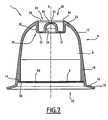
- the bottom 12 has a peripheral region 23, extending radially inwards from the side wall 10, and a central region 24.
- the peripheral region 23 is rounded. It extends radially inwards and axially towards the rear from the side wall 10, and has a concavity turned towards the inside of the body 4.
- the central region 24 includes an annular rib 26 projecting axially inwardly of the body 4 from the peripheral region 23.
- the annular rib 26 defines an annular trench 28 open to the exterior of the body 4 rearwardly.
- the annular rib 26 defines a hollow central stud 30 protruding axially from the bottom of the annular trench 28 by defining a recess within the body 4.
- the central region 24 has at least one zone of weakness 32 designed to break under the effect of a fluid under pressure.
- the zones of least resistance 32 are provided, for example, in the form of zones of lesser thickness in the central region 24, defined for example by indentations formed in the central region 24.
- Areas of least resistance 32 are provided in walls of the annular rib 26 and / or on the central stud 30.
- the annular rib 26 comprises an outer tubular portion 36 extending axially inwardly from the peripheral region 23, an inner tubular portion 34 delimiting a lateral face of the central stud 30 and a bottom portion. 38 extending radially between the outer portion 36 and the inner portion 34 imparting to the annular rib 26 a cross section substantially shaped "U".
- zones of least resistance 32 are provided in the bottom portion 38 and in the central stud 30 in the form of areas of lesser thickness.
- the central region 24 is devoid of zone of least resistance 32 in the central block 30.
- the annular rib 26 has areas of lower resistance 32 in the outer portion 36 and / or the inner portion 34 .
- the outer portion 36 and the inner portion 34 converge conferring on the annular rib 26 a cross section substantially shaped "V".
- areas of least resistance 32 may be provided in the outer portion 36, the inner portion 34 and / or the central pin 30.
- the annular trench 28 has an outer edge 44 angular, preferably beveled, at the junction between the annular rib 26 and the peripheral region 23.
- the outer edge 44 defines the rear end 20 of the capsule 1.
- the central stud 30 is axially recessed towards the interior of the body 4 with respect to the outer edge 44.
- the peripheral region 23 has an extra thickness along the outer edge 44, so as to strengthen the outer edge 44.
- the peripheral region 23 has for example an increasing thickness from the side wall 10 to the outer edge 44.
- the internal shoulder 14 is annular and protrudes radially from the side wall 10 towards the inside of the body 4. It is recessed axially towards the inside of the body 4 with respect to the front end 22 of the body 4 and at the edge ring 16.
- the cover 6 is fixed by its periphery to the internal shoulder 14 so that the cover 6 is disposed axially inwards towards the inside of the body 4 with respect to the front end 22 of the body 4.
- the distance of withdrawal of the cover 6 relative to the front end 22 of the body 4 is greater than 1 mm.
- the lid 6 closes the front end 22 of the body 4.
- the lid 6 comprises an outlet filter 49 capable of passing a fluid under pressure while retaining the substance contained in the chamber 8.
- the filter 49 is made of porous filter paper, woven plastic material or perforated plastic film.
- the lid 6 further comprises an air and water-tight membrane 50 doubling the filter 49.
- the membrane 50 has lines of weakness 52, so that the membrane 50 is able to tear under the sole the effect of the pressure of a liquid.
- lines of weakness 52 form a cross. Alternatively, they form a circle, circular arcs, or any other form adapted to allow optimal tearing of the membrane 50.
- the filter 49 is disposed between the chamber 8 and the membrane 50.
- the filter 49 and the membrane 50 are contiguous to each other.
- the filter 49 and the membrane 50 are for example in the form of a bilayer complex film.
- the annular flange 16 extends radially outwardly from the side wall 10.
- the annular flange 16 defines the front end 22 of the body 4.
- the flange 16 has a free marginal region 54. It does not support an attached sealing element or deformable sealing relief. As shown on the Figures 1 to 3 the annular flange 16 is substantially planar.
- the capsule 1 is intended to be disposed in an extraction device 350, represented on the Figures 4 and 5 .
- the extraction device 350 comprises a hollow receiving element 352, defining a housing 353 for receiving the capsule 1, and a support 354. It is adapted to be operated between an open configuration in which the receiving element 352 and the 354 are mutually spaced apart to introduce the capsule 1 into the receiving member 352, and a closed position, shown in FIG. Figure 5 in which the receiving member 352 and the holder 354 are mutually brought together to inject the extraction liquid into the capsule 1.
- the device 350 is shown in an intermediate configuration in which it is partially open, but not yet sufficiently open to allow the introduction of the capsule 1.
- the housing 353 has an inner side face 360, a housing bottom 370 and a conduit 372 for supplying extraction liquid opening on the housing bottom 370, substantially in the center and an opening 316 for introducing the capsule 1.
- the inner side face 360 is of revolution about a longitudinal axis Y. In the example shown, it is substantially frustoconical.
- the longitudinal axes X of the capsule 1 and Y of the housing 353 merge substantially.
- the receiving member 352 has an annular edge 380 surrounding the opening 316.
- the capsule 1 has a sufficient axial length so that, in the closed configuration of the extraction device 350, the capsule 1 is supported by its annular rim 16 against the support 354 and by its bottom 12 against the housing bottom 370 along a line closed annular contact contact 122, preferably defined on the peripheral region 23 along the outer edge 44 of the annular trench 28.
- the capsule 1 is advantageously adapted to deform elastically under the effect of an axial compression force F to ensure sufficient contact between the bottom 12 and the housing bottom 370.
- the capsule 1 is adapted so that, under the effect of the axial compression force F, at least one annular zone 130 of the bottom 12 and / or the side wall 10 of the capsule 1 expands radially outwardly so as to ensure an additional contact 128 with the lateral face 360 of the housing 353, following a closed annular contact line.
- the capsule 1 is first placed in the device 350 in open configuration, then the device 350 is operated to move in closed configuration.
- the capsule 1 is supported by its annular flange 16 against the support 354 and the receiving element 352 bears axially on the bottom 12 of the capsule 1, so that the contact 122 is created , and the body 4 is deformed as a whole so that the contact 128 is created with the receiving element 352 of the device 350.
- the extraction fluid is injected under pressure through the conduit 372.
- the zones of weakness 32 of the central region 24 of the bottom 12 rupture and the extraction fluid enters the capsule 1.
- the bottom reinforced by an annular rib enables the body of the capsule to be made of a relatively flexible, deformable material, without the bottom collapsing towards the inside of the capsule under the effect of the fluid pressure.
- the convexity of the bottom makes it possible to define a resilient and elastically deformable bottom, with a volume of the large chamber making it possible to load a larger quantity of substance into the capsule.
- the rib delimiting in the outer face an annular trench makes it possible to improve the injection of the extraction liquid into the capsule.
- the presence of an annular rim makes it possible to increase the stability of the capsule on the support of the extraction device.
- the capsule has a cup-shaped body whose bottom is airtight and watertight, the body being closed by a seal that is airtight and watertight.
- the tightness of the capsule keeps the substance safe from air and moisture.
- the cover has a membrane tearing under the effect of the pressurized fluid allowing appropriate opening of the cap from a determined pressure level, with a beneficial delay effect for a quality extraction.
- the operculum recessed axially towards the inside of the body avoids any interference with the support of the extraction device before the opening of the membrane, and thus allows controlled opening of the capsule.
- the membrane associated with a filter ensures extraction of the substance under satisfactory pressure conditions with effective retention of the substance inside the capsule.
- the operculum provided in the form of a complex film facilitates the manufacture of the capsule at low cost.
- the capsule variants illustrated on the figures 6 and 7 differ from that of Figures 1 to 3 in that the marginal region 54 of the annular flange 16 is inclined towards the front of the capsule 1. As shown in FIG. Figure 6 the annular flange 16 is curved towards the front of the capsule 1. As shown in FIG. Figure 7 , the annular flange 16 is frustoconical flaring forward.
- Such a flange 16 makes it possible to guarantee and reinforce the contact 122 between the bottom 12 of the capsule 1 and the housing bottom 370 when the device 350 is closed, while being able to deform to allow the closure of the extraction device 350.
- the capsule 1000 according to a second embodiment of the invention, represented on the Figures 9 to 21 , includes, as visible on the Figures 9 and 10 , a hollow body 1004 and an outlet cap 1006 together defining an inner chamber 1008 containing a substance (not shown) for the preparation of a beverage.
- the body 1004 has a general cup shape and is airtight and watertight. It comprises an outer side wall 1010, a bottom 1012 closing a rear end 1020 of the body 1004, and an annular flange 1016 surrounding an open front end 1022 of the body 1004.
- the outer side wall 1010 and the bottom 1012 are made of material and are made of a first plastic material airtight and watertight.
- the first plastic material is chosen to be inert with respect to the substance contained in the capsule 1000.
- said first material is translucent and is not colored in the mass, so as to avoid the diffusion of the coloring. in the substance.
- the second plastic material is polyamide. Polyamide does not interfere with food products and is a very effective barrier to air and water.
- the annular flange 1016 is made of a second plastic material, different from the first plastic material.
- the second plastic material is preferably chosen to be a low cost material. Since it is not in contact with the substance, its properties vis-à-vis the substance do not take into account in the choice of the second material.
- the second plastic material is polyurethane, which is an inexpensive material.
- the first and second plastic materials are compatible materials, i.e. materials adapted to polymerize with each other.
- the second material is colored in the mass.
- the annular flanges 1016 of 1000 capsules containing different substances so as to easily distinguish a 1000 capsule containing a first substance of another 1000 capsule containing a second substance, different from the first.
- the outer side wall 1010 extends from the bottom 1012 along a longitudinal axis X to the front end 1022 of the body 1004.
- the outer side wall 1010 is substantially frustoconical of revolution about the longitudinal axis X. It is rigid. It has an inner surface 1010a, facing the chamber 1008, and an outer surface 1010b, opposite the inner surface 1010a.
- the bottom 1012 comprises a peripheral region 1023 and a central region 1024.
- Peripheral region 1023 is rigid. It is rounded and extends radially inwardly and axially rearwardly from the outer sidewall 1010, and has a concavity facing the interior of the body 1004. It thus extends from the outer sidewall 1010 to the rear end 1020 of the body 1004.
- the rear end 1020 is typically a closed line, for example a circle.
- Central region 1024 enters axially inward of chamber 1008 from the peripheral region.
- the central region 1024 thus defines in the bottom 1012 a recess 1028 outside the body 1004.
- the central region 1024 comprises an outer tubular portion 1036 extending axially inwardly of the chamber 1008 from the peripheral region 1023, a bottom portion 1038 extending radially inwardly from the inner end. of the outer potion 1036 and closing the recess 1028, and a central inner portion 1034 projecting outwardly from the bottom portion 1038.
- the inner portion 1034 defines a hollow central stud 1030 in the recess 1028.
- the latter thus has an annular shape.
- the outer portion 1036, the bottom portion 1038 and the inner portion 1034 define an annular rib 1026 in the central region 1024.
- the bottom portion 1038 comprises at least one zone 1032 of least resistance provided to break under the effect of a fluid under pressure.
- the or each zone of least resistance is provided to break at a pressure of the fluid under pressure of between 1 and 3 bar.
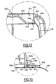
- the or each zone of least resistance 1032 is provided, for example, in the form of zones of lesser thickness, as shown in FIG. Figure 12 . As long as the or each zone of weakness 1032 is not broken, the bottom 1012, and by extension the entire body 1004, is impermeable to air and liquids.
- the zone of least resistance is defined at the periphery of the bottom portion 1038, at the junction between the bottom portion 1038 and the outer portion 1036.
- the zone of least resistance is in the form of a circular arc.
- the arc of the circle preferably extends over at least 270 °.
- the shape of the inner portion 1034 conditions the axial shear force generated by a pressurized liquid present in the recess 1028.
- the inner portion 1034 has a frustoconical shape, widening from the back to the front of the capsule 1000, and protruding outwardly.
- the inner portion 1034 extends in a radial plane. At a determined pressure of the fluid present in the recess 1028, a flat inner portion 1034 induces a higher shear force than an inner portion protruding outwardly.
- the body 1004 also comprises longitudinal ribs 1042 for stiffening the outer side wall 1010 and radial ribs 1044 for stiffening the bottom 1012.
- Each longitudinal rib 1042 extends longitudinally along the outer sidewall 1010, preferably, as shown, along the inner surface 1010a.
- the longitudinal ribs are adapted to promote the emulsion between the pressurized fluid and the substance contained in the chamber 1008.
- each longitudinal rib 1042 extends along the outer surface 1010b.
- Each radial rib 1044 extends radially between the outer portion 1036 and the peripheral region 1023.
- the radial ribs 1044 stiffen the bottom 12 and thus promote the generation of shear forces induced by the pressure of the fluid under directly on the or each zone of weakness 1032.
- each radial rib 1044 extends in the extension of a longitudinal rib 1042.
- the annular flange 1016 extends radially outwardly from an inner annular rim 1046 to an outer annular rim 1048 from the outer surface 1010b of the outer sidewall 1010. It defines the leading end 1022 of the body 1004. It does not support an attached sealing element or deformable sealing relief. Preferably, it is substantially plane.
- the outer annular border 1048 is free.
- the outer surface 1010b of the outer side wall 1010 defines, near the front end 1022 of the body 1004, an annular clearance 1049 defining a shoulder 1050 and a groove 1052 connecting the annular flange 1016 to the outer side wall 1010.
- the shoulder 1050 is recessed rearwardly relative to the front end 1022. It extends radially and parallel to the front end 1022, between an inner end 1054 and an outer end 1056.
- the groove 1052 is formed in the shoulder 1050 and protrudes longitudinally rearwardly from the inner end 1054 of the shoulder 1050.
- the annular flange 1016 comprises an annular protuberance 1058 protruding longitudinally from the inner annular rim 1046 in the groove 1052.
- the protuberance 1058 cooperates with the groove 1052 to strengthen the connection of the annular flange 1016 to the outer side wall 1010.
- a portion of the outer side wall 1010 extends between the annular flange 1016 and the chamber 1008, which prevents the substance from being in contact with the second material.
- the lid 1006 is fixed by its periphery to the outer side wall 1010 and the annular flange 1016. The lid 1006 thus closes the front end 1022 of the body 1004.
- the lid 1006 comprises an output filter 1060 adapted to let a fluid under pressure by retaining the substance contained in the chamber 1008.
- the filter 1060 is porous filter paper, woven plastic material or perforated plastic film.
- the filter 1060 is, as shown, set back from the front end 1022, to the chamber 1008, and is fixed on its periphery to the inner surface 1010a of the outer side wall 1010.
- the filter 1060 is for example disposed between 1 and 1.5 mm recessed from the front end 1022.
- the lid 1006 further comprises an airtight and water-tight membrane 1062 doubling the filter 1060.
- the membrane 1062 is fixed, for example welded, to the annular flange 1016.
- the membrane 1062 extends along the front end 1022 of the body 1004. The membrane 1062 makes it possible to preserve the substance in an inert atmosphere, so as to avoid any oxidation of the substance.
- the membrane 1062 is peelable, that is to say it can be easily detached from the body 1004.
- it comprises a tongue 1064 extending radially outwardly from the annular flange 1016, to allow a user to easily remove the membrane 1062 before use of the capsule 1000 in an extraction device.
- the membrane 1062 has lines of weakness (not shown), so that the membrane 1062 is able to tear under the sole effect of the pressure of a liquid.
- the extraction can still be performed normally, without risk of damage to the extraction device .
- the filter 1060 is disposed between the chamber 1008 and the membrane 1062.
- the gap between the filter 1060 and the membrane 1062 is preferably filled with an inert gas, typically with nitrogen.
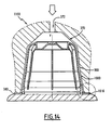
- the capsule 1000 is represented on the Figure 14 inserted into an 1100 beverage extraction device.
- This device 1100 is similar to the extraction device 350 described above. Similar elements are designated by the same reference signs.
- the capsule 1000 is adapted so that the annular edge 380 comes into contact with the annular flange 1016 when the extraction device 1100 is in closed configuration.
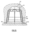
- a variant of the extraction device 1100 is represented on the Figure 15 .
- the conduit 372 for supplying extraction liquid is offset radially with respect to the longitudinal axis Y.
- the capsule 1000 is also adapted for use in drink extraction devices where the arrival of liquid under pressure in the receiving housing 353 is not in the center of the housing 353.
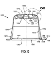
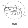
- a variant of the 1000 capsule is presented on Figures 16 and 17 .
- the internal portion 1034 has a hemispherical shape concavity oriented towards the inside of the body 1004. This shape is adapted to allow the rupture of the zone of weakness 1032 at higher pressures in the case where the inner portion 1034 has a frustoconical shape.
- the annular flange 1016 is not bonded to the outer surface 1010b of the outer side wall 1010, but to a front annular face 1066 of the outer side wall 1010. Said front annular face 1066 defines a groove 1068 protruding longitudinally toward the outside. rear and with which cooperates the protuberance 1058 of the annular flange 1016 to strengthen the connection of the annular flange 1016 with the outer side wall 1010.
- the inner surface 1010a of the outer side wall 1010 defines an annular inner shoulder 1070 extending in a radial plane and facing forward.
- the inner shoulder 1070 is recessed axially inwardly of the body 1004 with respect to the front end 1022 of the body 1004 and the annular flange 1016. This inner shoulder 1070 is adapted to support the lid 1006.
- the inner shoulder 1070 is set back relative to the front annular face 1066, the substance is thus not in contact with the second material forming the annular flange 1016.
- the lid 1006 is constituted by a bilayer complex film comprising the filter 1060 and the membrane 1062.
- This complex film is fixed by its periphery on the internal shoulder 1070 so that the lid 1006 is disposed axially inwardly of the body 1004 with respect to the front end 1022 of the body 1004.
- the retraction distance of the lid 1006 from the front end 1022 of the body 1004 is greater than at 1 mm.
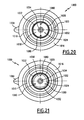
- the bottom portion 1038 comprises a plurality of zones of least resistance 1032, each being formed by two lines of weakness intersecting so as to form a cross.
- the zones of least resistance 1032 are four in number. Alternatively, the number of zones of least resistance 1032 is different.
- the bottom portion 1038 comprises a plurality of zones of least resistance 1032, each being formed by a closed circular line of weakness, each delimiting a disk not including the inner portion 1034.
- the areas of less resistance 1032 are three in number. Alternatively, the number of zones of least resistance 1032 is different.
- the bottom portion 1038 comprises two zones of least resistance 1032, each having the shape of a serrated semicircle and extending at the periphery of the bottom portion 1038, along the junction with the outer portion 1036.
- the bottom 12 further comprises two reinforcing ribs 1080 of the central region 1024.
- Each rib 1080 extends longitudinally between the tubular portion 1026 and the peripheral rim 1030.
- Each rib 1080 is interposed between the two zones 1034 of the least resistance. the example shown, the ribs 1080 are thus diametrically opposed to one another.
- These ribs 1080 are intended to concentrate the shear forces due to the force exerted by the pressurized fluid on the bottom 1012 in the extraction device 1100 on the zones of least resistance 1034.
- the bottom portion 1038 comprises three zones of least resistance 1032, each being constituted by a closed line delimiting a crescent whose long side extends along the outer portion 1036.
- the bottom 1012 also comprises reinforcing ribs 1080 of the central region 1024. These ribs 1080 are here three in number and each is interposed between two zones of weakness 1032.
- the bottom portion 1038 comprises a single zone of weakness 1032 consisting of a closed circular line extending along the outer portion 1036.
- the first plastic material is poured, for example injected, into a mold, to form the bottom 1012 and the outer side wall 1010. Then, in a second step, the second plastic material is in turn poured into the mold. mold, so as to form the annular flange 1016.
- the first and second plastic materials being compatible materials, they bind chemically. In particular, a part of the molecules of the first material diffuses into the second material and vice versa. Thus, a thin layer is formed in which the two materials are mixed and the two materials are thus intimately bonded to each other.
- the body part of the capsule in contact with the substance is formed in a material which is inert with respect to the substance, which makes it possible to preserve the substance under optimal conditions, without the risk of degradation of the substance.
- the substance by oxidation or by toxic elements contained in the material in contact with the substance.
- the fact that the first plastic material is not colored in the mass makes it possible to reduce the probability of migration of toxic elements from the capsule to the substance.
- the fact of using a second material for the annular rim makes it possible to reduce the manufacturing cost of the capsule and also makes it possible, by coloring the second material, to easily identify the substance contained in the chamber of the capsule, without risk of migration of the pigments into the substance, the latter not being in contact with the second material.
Description
- La présente invention concerne une capsule pour l'extraction d'une boisson sous pression, du type comprenant un corps en forme de coupelle et un opercule délimitant ensemble une chambre contenant une substance pour la préparation d'une boisson, le corps comprenant une paroi latérale extérieure sensiblement tronconique et un fond venu de matière avec la paroi latérale et fermant la paroi latérale extérieure à une extrémité arrière du corps, l'opercule fermant la paroi latérale extérieure à l'extrémité avant du corps, la capsule étant adaptée pour être disposée dans un dispositif d'extraction de sorte qu'un liquide d'extraction sous pression pénètre dans la capsule par le fond et en sorte par l'opercule.
-
FR 2 373 999 - Il existe un risque qu'une telle capsule s'affaisse lors de la fermeture du dispositif d'extraction de boisson et/ou de l'injection du liquide sous pression
- En outre, de telles capsules sont particulièrement chères à produire, en particulier quand elles sont produites en grandes séries.
- Enfin, lorsqu'une telle capsule est utilisée dans un dispositif d'extraction comportant un logement de réception de la capsule et un support contre lequel est appliquée la capsule, l'opercule est plaqué contre le support, ce qui empêche un écoulement satisfaisant du liquide à travers la capsule.
- Le document
WO 2005/066040 A2 décrit en outre un autre type de capsule de l'art antérieur. - Un but de l'invention est de fournir une capsule permettant de limiter le risque d'affaissement tout en permettant l'extraction d'une boisson. D'autres buts de l'invention sont de proposer une capsule pouvant être facilement calibrée de façon à ajuster le niveau de pression auquel le liquide d'extraction pénètre dans la capsule, de proposer une capsule à coût réduit, et de fournir une capsule compatible avec de nombreux dispositifs d'extraction de boisson.
- A cet effet, un premier aspect de l'invention concerne une capsule selon l'objet de la revendication 1.
- Selon d'autres modes de réalisation, la capsule comporte une ou plusieurs des caractéristiques suivantes, prise(s) isolément ou suivant toute(s) combinaison(s) techniquement possible(s) :
- la région centrale comprend une portion de fond et un plot central faisant saillie depuis la portion de fond vers l'extérieur,
- la région centrale comprend une nervure annulaire faisant saillie vers l'intérieur du corps, l'évidement présentant la forme d'une tranchée annulaire à l'extérieur du corps,
- la région centrale comprend une portion de fond plate fermant axialement l'évidement,
- la ou chaque région de moindre résistance est formée dans la portion de fond,
- le fond comprend au moins une nervure de renforcement de la région centrale,
- le corps comprend au moins une nervure radiale de rigidification de la région périphérique,
- avant rupture de la ou chaque zone de moindre résistance, le fond et la paroi latérale extérieure du corps sont imperméables à l'air et aux liquides,
- le plot central a une forme tronconique,
- le plot central a une forme hémisphérique,
- l'opercule comprend un filtre et une membrane,
- le filtre est disposé en retrait de l'extrémité avant du corps, vers la chambre, la membrane s'étendant le long de l'extrémité avant,
- l'espace entre le filtre et la membrane est rempli d'azote,
- la membrane est pelable,
- la paroi latérale extérieure et le fond sont formés d'une première matière plastique, et le corps comprend un rebord annulaire s'étendant radialement vers l'extérieur depuis la paroi latérale extérieure et délimitant l'extrémité avant du corps, ledit rebord annulaire étant formé d'une deuxième matière plastique, différente de la première matière plastique,
- la région centrale comprend une portion externe tubulaire s'étendant axialement vers l'intérieur de la chambre à partir de la région périphérique, la ou chaque zone de moindre résistance étant formée à la jonction entre la portion de fond et la portion externe,
- la ou chaque zone de moindre résistance est adaptée pour se rompre à une pression du liquide sous pression comprise entre 1 et 3 bars.
- Selon d'autres modes de réalisation, ladite capsule comporte une ou plusieurs des caractéristiques suivantes, prise(s) isolément ou suivant toute(s) combinaison(s) techniquement possible(s) :
- le fond comporte une région centrale comportant une nervure annulaire de renforcement du fond faisant saillie vers l'intérieur du corps et délimitant une tranchée annulaire à l'extérieur du corps
- la nervure annulaire possède une section en U définie par deux portions latérales reliées par une base, au moins une zone de faiblesse étant définie dans la base ;
- la nervure annulaire définit un plot central entouré par la tranchée annulaire, le plot central comprenant au moins une zone de moindre résistance ;
- le fond comprend une région périphérique arrondie à concavité tournée vers l'intérieur du corps ;
- le fond et la paroi latérale du corps sont étanches à l'air et à l'eau ;
- le corps comporte un rebord annulaire s'étendant radialement vers l'extérieur depuis la paroi latérale, le rebord définissant une extrémité de la capsule à l'opposé du fond ;
- l'opercule comprend un filtre ;
- l'opercule comprend une membrane étanche à l'air et à l'eau ; et
- la membrane est munie de lignes d'affaiblissement pour l'ouverture de la membrane sous l'effet de la seule pression d'un fluide sous pression.
- >
- Selon d'autres modes de réalisation, ladite capsule comporte une ou plusieurs des caractéristiques suivantes, prise(s) isolément ou suivant toute(s) combinaison(s) techniquement possible(s) :
- le filtre et la membrane sont disposés en retrait par rapport à l'extrémité avant du corps
- la paroi latérale comporte un épaulement interne en retrait par rapport à l'extrémité avant du corps, le filtre et la membrane étant fixés sur l'épaulement interne.
- la distance de retrait de la membrane de sortie par rapport à l'extrémité avant est supérieure à 1 mm ;
- la membrane de sortie est étanche à l'air et à l'eau ;
- la membrane de sortie comporte au moins une ligne de rupture ;
- le filtre de sortie est disposé entre la chambre et la membrane de sortie ;
- le filtre et la membrane de sortie sont accolés l'un à l'autre ;
- le filtre de sortie est en matériau plastique tissé ou perforé ; et
- la membrane est un film en matière plastique ou métallique, en particulier en aluminium.
- Un deuxième aspect de l'invention concerne un système comprenant une capsule selon l'invention, et un dispositif d'extraction comportant un logement destiné à recevoir la capsule, un support et un conduit d'amenée de liquide d'extraction.
- L'invention sera mieux comprise à la lecture de la description qui va suivre, donnée uniquement à titre d'exemple et faite en se référant aux dessins annexés, sur lesquels :
- la
Figure 1 représente une vue en perspective d'une première variante d'une capsule selon un premier mode de réalisation de l'invention ; - la
Figure 2 est une vue en coupe longitudinale de la capsule de laFigure 1 ; - la
Figure 3 est une vue de face de la capsule de laFigure 1 ; - les
Figures 4 et5 sont des vues de la capsule de laFigure 1 , installée dans un dispositif d'extraction en configurations respectivement partiellement ouverte et fermée ; - la
Figure 6 est une vue en coupe longitudinale d'une seconde variante de la capsule selon le premier mode de réalisation ; - la
Figure 7 est une vue en coupe longitudinale d'une troisième variante de la capsule selon le premier mode de réalisation ; - la
Figure 8 est une vue de la capsule de laFigure 6 , installée dans un dispositif d'extraction en configuration fermée ; - la
Figure 9 est une vue en perspective d'une première variante d'une capsule selon un deuxième mode de réalisation de l'invention ; - la
Figure 10 est une vue en coupe longitudinale de la capsule de laFigure 9 ; - la
Figure 11 est une vue de derrière de la capsule de laFigure 9 ; - la
Figure 12 est une vue d'un détail marqué XII sur laFigure 10 ; - la
Figure 13 est une vue d'un détail marqué XIII sur laFigure 10 ; - la
Figure 14 est une vue de la capsule de laFigure 8 , installée dans un premier dispositif d'extraction en configuration fermée ; - la
Figure 15 est une vue similaire à laFigure 14 , la capsule étant installée dans un deuxième dispositif d'extraction en configuration fermée ; - la
Figure 16 est une vue en coupe longitudinale d'une deuxième variante d'une capsule selon le deuxième mode de réalisation ; - la
Figure 17 est une vue d'un détail marqué XVII sur laFigure 16 ; - la
Figure 18 est une vue de derrière d'une troisième variante d'une capsule selon le deuxième mode de réalisation ; - la
Figure 19 est une vue de derrière d'une quatrième variante d'une capsule selon le deuxième mode de réalisation ; - la
Figure 20 est une vue de derrière d'une cinquième variante d'une capsule selon le deuxième mode de réalisation ; - la
Figure 21 est une vue de derrière d'une sixième variante d'une capsule selon le deuxième mode de réalisation ; et - la
Figure 22 est une vue de derrière d'une septième variante d'une capsule selon le deuxième mode de réalisation. - La capsule 1 selon une premier mode de réalisation de l'invention, représentée sur les
Figures 1 à 3 , comporte un corps 4 creux et un opercule 6 de sortie délimitant ensemble une chambre 8 intérieure contenant une substance (non représentée) pour la préparation d'une boisson. - Le corps 4 présente une forme générale de coupelle et comprend une paroi latérale 10, un fond 12 fermant une extrémité arrière 20 fermée du corps 4, et un rebord annulaire 16 entourant une extrémité avant 22 ouverte du corps 4.
- Le corps 4 est réalisé d'un seul tenant. La paroi latérale 10, le fond 12 et le rebord annulaire 16 sont venus de matière. Le corps 4 est réalisé en un matériau étanche à l'air et à l'eau dans un matériau plastique ou dérivé du plastique.
- La paroi latérale 10 s'étend à partir du fond 12 suivant un axe longitudinal X jusqu'à l'extrémité avant 22 du corps 4.
- La paroi latérale 10 comprend un épaulement intérieur 14. L'épaulement 14 s'étend dans un plan radial et est orienté vers l'avant.
- La paroi latérale 10 est sensiblement tronconique de révolution autour de l'axe longitudinal X. La paroi latérale 10 comprend un tronçon arrière 18, relativement souple, s'étendant à partir du fond 12 et un tronçon avant 19, relativement rigide, prolongeant axialement le tronçon arrière 18. Le tronçon avant 19 présente une épaisseur croissante axialement, supérieure à celle du tronçon arrière 18.
- Le fond 12 présente une région périphérique 23, s'étendant radialement vers l'intérieur à partir de la paroi latérale 10, et une région centrale 24.
- La région périphérique 23 est arrondie. Elle s'étend radialement vers l'intérieur et axialement vers l'arrière à partir de la paroi latérale 10, et présente une concavité tournée vers l'intérieur du corps 4.
- La région centrale 24 comprend une nervure annulaire 26 faisant saillie axialement vers l'intérieur du corps 4 à partir de la région périphérique 23. La nervure annulaire 26 définit une tranchée annulaire 28 ouverte à l'extérieur du corps 4 vers l'arrière. La nervure annulaire 26 définit un plot central 30 creux faisant saillie axialement à partir du fond de la tranchée annulaire 28 en définissant un évidement à l'intérieur du corps 4.
- La région centrale 24 présente au moins une zone de moindre résistance 32 prévue pour rompre sous l'effet d'un fluide sous pression. Les zones de moindre résistance 32 sont prévues par exemple sous la forme de zones de moindre épaisseur de la région centrale 24, définies par exemple par des indentations ménagée dans la région centrale 24.
- Les zones de moindre résistance 32 sont prévues dans des parois de la nervure annulaire 26 et/ou sur le plot central 30.
- Dans l'exemple illustré, la nervure annulaire 26 comprend une portion externe 36 tubulaire s'étendant axialement vers l'intérieur à partir de la région périphérique 23, une portion interne 34 tubulaire délimitant une face latérale du plot central 30 et une portion de fond 38 s'étendant radialement entre la portion externe 36 et la portion interne 34 en conférant à la nervure annulaire 26 une section transversale sensiblement en forme de « U ».
- Comme représenté sur la
Figure 2 , des zones de moindre résistance 32 sont prévues dans la portion de fond 38 et dans le plot central 30 sous la forme de zones de moindre épaisseur. - En variante, la région centrale 24 est dépourvue de zone de moindre résistance 32 dans le plot central 30. En variante ou en option, la nervure annulaire 26 possède des zones de moindre résistance 32 dans la portion externe 36 et/ou la portion interne 34.
- Dans une autre variante possible différente de celle de la
figure 2 par la forme de la nervure annulaire 26, la portion externe 36 et la portion interne 34 convergent en conférant à la nervure annulaire 26 une section transversale sensiblement en forme de « V ». Dans ce cas, des zones de moindre résistance 32 peuvent être prévues dans la portion externe 36, la portion interne 34 et/ou le plot central 30. - Comme représenté sur la
Figure 2 , la tranchée annulaire 28 présente un bord extérieur 44 anguleux, de préférence biseauté, à la jonction entre la nervure annulaire 26 et la région périphérique 23. Le bord extérieur 44 délimite l'extrémité arrière 20 de la capsule 1. Le plot central 30 est axialement en retrait vers l'intérieur du corps 4 par rapport au bord extérieur 44. - De préférence, la région périphérique 23 possède une surépaisseur le long du bord extérieur 44, de façon à renforcer le bord extérieur 44. La région périphérique 23 présente par exemple une épaisseur croissante depuis la paroi latérale 10 vers le bord extérieur 44.
- L'épaulement interne 14 est annulaire et fait saillie radialement depuis la paroi latérale 10 vers l'intérieur du corps 4. Il est en retrait axialement vers l'intérieur du corps 4 par rapport à l'extrémité avant 22 du corps 4 et au rebord annulaire 16.
- L'opercule 6 est fixé par sa périphérie sur l'épaulement interne 14 de sorte que l'opercule 6 est disposé en retrait axialement vers l'intérieur du corps 4 par rapport à l'extrémité avant 22 du corps 4. De préférence, la distance de retrait de l'opercule 6 par rapport à l'extrémité avant 22 du corps 4 est supérieure à 1 mm.
- L'opercule 6 ferme l'extrémité avant 22 du corps 4.
- L'opercule 6 comprend un filtre 49 de sortie propre à laisser passer un fluide sous pression en retenant la substance contenue dans la chambre 8. Le filtre 49 est en papier filtre poreux, en matériau plastique tissé ou en film plastique perforé.
- L'opercule 6 comprend en outre une membrane 50 étanche à l'air et à l'eau doublant le filtre 49. La membrane 50 présente des lignes d'affaiblissement 52, de sorte que la membrane 50 est propre à se déchirer sous le seul l'effet de la pression d'un liquide. Dans l'exemple représenté sur les
Figures 1 et3 , les lignes d'affaiblissement 52 forment une croix. En variante, elles forment un cercle, des arcs de cercle, ou toute autre forme adaptée pour permettre un déchirement optimal de la membrane 50. - Le filtre 49 est disposé entre la chambre 8 et la membrane 50. Le filtre 49 et la membrane 50 sont accolés l'un à l'autre. Le filtre 49 et la membrane 50 se présentent par exemple sous la forme d'un film complexe bicouche.
- Le rebord annulaire 16 s'étend radialement vers l'extérieur à partir de la paroi latérale 10. Le rebord annulaire 16 définit l'extrémité avant 22 du corps 4. Le rebord 16 présente une région marginale 54 libre. Il ne supporte pas d'élément d'étanchéité rapporté ou de relief d'étanchéité déformable. Tel que représenté sur les
figures 1 à 3 , le rebord annulaire 16 est sensiblement plan. - La capsule 1 est destinée à être disposée dans un dispositif d'extraction 350, représenté sur les
Figures 4 et5 . - Le dispositif d'extraction 350 comporte un élément de réception 352 creux, délimitant un logement 353 de réception du la capsule 1, et un support 354. Il est propre à être manoeuvré entre une configuration ouverte dans laquelle l'élément de réception 352 et le support 354 sont mutuellement écarté pour introduire la capsule 1 dans l'élément de réception 352, et une position fermée, représentée sur la
Figure 5 , dans laquelle l'élément de réception 352 et le support 354 sont mutuellement rapprochés, pour injecter le liquide d'extraction dans la capsule 1. Sur laFigure 4 , le dispositif 350 est représenté dans une configuration intermédiaire dans laquelle il est partiellement ouvert, mais toutefois pas suffisamment ouvert pour permettre l'introduction de la capsule 1. - Le logement 353 présente une face latérale intérieure 360, un fond de logement 370 et un conduit 372 d'amenée de liquide d'extraction débouchant sur le fond de logement 370, sensiblement au centre et une ouverture 316 d'introduction de la capsule 1.
- La face latérale intérieure 360 est de révolution autour d'un axe longitudinal Y. Sur l'exemple représenté, elle est sensiblement tronconique. Lorsque la capsule 1 est placée dans le dispositif d'extraction 350, les axes longitudinaux X de la capsule 1 et Y du logement 353 se confondent sensiblement.
- L'élément de réception 352 présente un bord annulaire 380 entourant l'ouverture 316.
- La capsule 1 présente une longueur axiale suffisante pour que, en configuration fermée du dispositif d'extraction 350, la capsule 1 soit en appui par son rebord annulaire 16 contre le support 354 et par son fond 12 contre le fond de logement 370 suivant une ligne de contact annulaire fermée 122, définie de préférence sur la région périphérique 23 le long du bord extérieur 44 de la tranchée annulaire 28.
- La capsule 1 est avantageusement adaptée pour se déformer élastiquement sous l'effet d'une force axiale F de compression pour assurer un contact suffisant entre le fond 12 et le fond de logement 370.
- En option la capsule 1 est adaptée pour que, sous l'effet de la force axiale F de compression, au moins une zone annulaire 130 du fond 12 et/ou de la paroi latérale 10 de la capsule 1 se dilate radialement vers l'extérieur de façon à assurer un contact 128 supplémentaire avec la face latérale 360 du logement 353, suivant une ligne de contact annulaire fermée.
- Le procédé d'extraction de la capsule 1 par le dispositif d'extraction 350 va maintenant être décrit.
- La capsule 1 est d'abord placée dans le dispositif 350 en configuration ouverte, puis le dispositif 350 est manoeuvré pour se déplacer en configuration fermée.
- Lors de ce déplacement vers la configuration fermée, la capsule 1 vient en appui par son rebord annulaire 16 contre le support 354 puis l'élément de réception 352 appuie axialement sur le fond 12 de la capsule 1, de sorte que le contact 122 se crée, et le corps 4 se déforme dans son ensemble de sorte que le contact 128 se crée avec l'élément de réception 352 du dispositif 350.
- Une fois le dispositif 350 en configuration fermée, le fluide d'extraction est injecté sous pression par le conduit 372. Sous l'effet de la pression du fluide d'extraction, les zones de moindre résistance 32 de la région centrale 24 du fond 12 se rompent et le fluide d'extraction pénètre dans la capsule 1.
- La pression de liquide dans la capsule 1 augmente alors et, sous l'effet de cette pression, la membrane de sortie 50 se déchire. Le fluide s'échappe alors hors de la capsule 1 en traversant l'opercule 6 en étant filtré par le filtre 49.
- Grâce à l'invention, le fond renforcé par une nervure annulaire permet de réaliser le corps de la capsule en un matériau relativement souple, déformable, sans que le fond ne s'effondre vers l'intérieur de la capsule sous l'effet de la pression de fluide. La convexité du fond permet de définir un fond résistant et déformable élastiquement, avec un volume de la chambre important permettant de charger une plus grande quantité de substance dans la capsule. La nervure délimitant dans la face extérieure une tranchée annulaire permet d'améliorer l'injection du liquide d'extraction dans la capsule. La présence d'un rebord annulaire permet d'augmenter la stabilité de la capsule sur le support du dispositif d'extraction.
- La capsule possède un corps en forme de coupelle dont le fond est étanche à l'air et à l'eau, le corps étant fermée par un opercule étanche à l'air et à l'eau. L'étanchéité de la capsule permet de conserver la substance à l'abri de l'air et de l'humidité. L'opercule possède une membrane se déchirant sous l'effet du fluide sous pression permettant une ouverture appropriée de l'opercule à partir d'un niveau de pression déterminé, avec un effet retard bénéfique pour une extraction de qualité. L'opercule en retrait axialement vers l'intérieur du corps évite toute interférence avec le support du dispositif d'extraction avant l'ouverture de la membrane, et permet ainsi une ouverture maîtrisée de la capsule. La membrane associée à un filtre permet d'assurer une extraction de la substance dans des conditions de pression satisfaisantes avec une retenue efficace de la substance à l'intérieur de la capsule. L'opercule fourni sous la forme d'un film complexe facilite la fabrication de la capsule à faible coût.
- Les variantes de capsule illustrées sur les
figures 6 et7 diffèrent de celle desfigures 1 à 3 en ce que la région marginale 54 du rebord annulaire 16 est inclinée vers l'avant de la capsule 1. Tel que représenté sur laFigure 6 , le rebord annulaire 16 est incurvé vers l'avant de la capsule 1. Tel que représenté sur laFigure 7 , le rebord annulaire 16 est tronconique s'évasant vers l'avant. - Tel qu'illustré sur la
figure 8 , lors de la fermeture du dispositif d'extraction 350, sous l'effet de la force d'appui exercée par le support 354, le rebord annulaire 16 se déforme en s'aplanissant. - Un tel rebord 16 permet de garantir et de renforcer le contact 122 entre le fond 12 de la capsule 1 et le fond de logement 370 à la fermeture du dispositif 350, tout en pouvant se déformer pour permettre la fermeture du dispositif d'extraction 350.
- La capsule 1000 selon une deuxième mode de réalisation de l'invention, représentée sur les
Figures 9 à 21 , comprend, comme visible sur lesFigures 9 et10 , un corps 1004 creux et un opercule 1006 de sortie délimitant ensemble une chambre 1008 intérieure contenant une substance (non représentée) pour la préparation d'une boisson. - Le corps 1004 présente une forme générale de coupelle et est étanche à l'air et à l'eau. Il comprend une paroi latérale extérieure 1010, un fond 1012 fermant une extrémité arrière 1020 du corps 1004, et un rebord annulaire 1016 entourant une extrémité avant 1022 ouverte du corps 1004.
- La paroi latérale extérieure 1010 et le fond 1012 sont venus de matière et sont réalisés en un premier matériau plastique étanche à l'air et à l'eau. Le premier matériau plastique est choisi pour être inerte vis-à-vis de la substance contenue dans la capsule 1000. De préférence, ledit premier matériau est translucide et n'est pas coloré dans la masse, de façon à éviter la diffusion de la coloration dans la substance. Typiquement, le deuxième matériau plastique est du polyamide. Le polyamide n'interfère pas avec les produits alimentaires et constitue une barrière à l'air et à l'eau très performante.
- De préférence, le rebord annulaire 1016 est constitué d'un deuxième matériau plastique, différent du premier matériau plastique. Le deuxième matériau plastique est préférentiellement choisi pour être un matériau de faible coût. Celui-ci n'étant pas en contact avec la substance, ses propriétés vis-à-vis de la substance n'entrent pas en compte dans le choix du deuxième matériau. Typiquement, le deuxième matériau plastique est du polyuréthane, qui est un matériau peu coûteux.
- De préférence, les premier et deuxième matériaux plastiques sont des matériaux compatibles, c'est-à-dire des matériaux adaptés pour polymériser l'un avec l'autre.
- Ainsi, il est possible de produire des capsules 1000 à coût réduit. Ces capsules étant destinées à être produites en très grandes séries, cela permet de réaliser des économies importantes.
- De préférence, le deuxième matériau est coloré dans la masse. Ainsi, il est possible de colorer différemment les rebords annulaires 1016 de capsules 1000 contenant différentes substances, de façon à distinguer aisément une capsule 1000 contenant une première substance d'une autre capsule 1000 contenant une deuxième substance, différente de la première.
- La paroi latérale extérieure 1010 s'étend à partir du fond 1012 suivant un axe longitudinal X jusqu'à l'extrémité avant 1022 du corps 1004.
- La paroi latérale extérieure 1010 est sensiblement tronconique de révolution autour de l'axe longitudinal X. Elle est rigide. Elle présente une surface intérieure 1010a, orientée vers la chambre 1008, et une surface extérieure 1010b, à l'opposée de la surface intérieure 1010a.
- Le fond 1012 comprend une région périphérique 1023 et une région centrale 1024.
- La région périphérique 1023 est rigide. Elle est arrondie et s'étend radialement vers l'intérieur et axialement vers l'arrière à partir de la paroi latérale extérieure 1010, et présente une concavité tournée vers l'intérieur du corps 1004. Elle s'étend ainsi depuis la paroi latérale extérieure 1010 jusqu'à l'extrémité arrière 1020 du corps 1004. L'extrémité arrière 1020 est typiquement une ligne fermée, par exemple un cercle.
- La région centrale 1024 rentre axialement vers l'intérieur de la chambre 1008 à partir de la région périphérique. La région centrale 1024 définit ainsi dans le fond 1012 un évidement 1028 à l'extérieur du corps 1004.
- La région centrale 1024 comprend une portion externe 1036 tubulaire s'étendant axialement vers l'intérieur de la chambre 1008 à partir de la région périphérique 1023, une portion de fond 1038 s'étendant radialement vers l'intérieur à partir de l'extrémité intérieure de la potion externe 1036 et fermant l'évidement 1028, et une portion interne 1034 centrale faisant saillie vers l'extérieur à partir de la portion de fond 1038.
- La portion interne 1034 définit un plot central creux 1030 dans l'évidement 1028. Celui-ci présente ainsi une forme annulaire. La portion externe 1036, la portion de fond 1038 et la portion interne 1034 définissent une nervure 1026 annulaire dans la région centrale 1024.
- La portion de fond 1038 comprend au moins une zone de moindre résistance 1032 prévue pour rompre sous l'effet d'un fluide sous pression. De préférence, la ou chaque zone de moindre résistance est prévue pour rompre à une pression du fluide sous pression comprise entre 1 et 3 bars.
- La ou chaque zone de moindre résistance 1032 est prévue par exemple sous la forme de zones de moindre épaisseur de, comme représenté sur la
Figure 12 . Tant que la ou chaque zone de moindre résistance 1032 n'est pas rompue, le fond 1012, et par extension l'ensemble du corps 1004, est imperméable à l'air et aux liquides. - Dans l'exemple illustré sur la
Figure 11 , la zone de moindre résistance est définie à la périphérie de la portion de fond 1038, à la jonction entre la portion de fond 1038 et la portion externe 1036. La zone de moindre résistance présente la forme d'un arc de cercle. L'arc de cercle s'étend de préférence sur au moins 270°. - La forme de la portion interne 1034 conditionne l'effort de cisaillement axial généré par un liquide sous pression présent dans l'évidement 1028.
- Dans le mode de réalisation des
figures 9 à 15 , la portion interne 1034 présente une forme tronconique, s'élargissant de l'arrière vers l'avant de la capsule 1000, et saillante vers l'extérieur. - En variante, la portion interne 1034 est s'étend dans un plan radial. A une pression déterminée du fluide présent dans l'évidement 1028, une portion interne 1034 plane induit un effort de cisaillement plus élevé qu'une portion interne saillante vers l'extérieur.
- Le corps 1004 comprend également des nervures longitudinales 1042 de rigidification de la paroi latérale extérieure 1010 et des nervures radiales 1044 de rigidification du fond 1012.
- Chaque nervure longitudinale 1042 s'étend longitudinalement le long de la paroi latérale extérieure 1010, de préférence, comme représenté, le long de la surface intérieure 1010a. Ainsi, les nervures longitudinales sont adaptées pour favoriser l'émulsion entre le fluide sous pression et la substance contenue dans la chambre 1008. En variante, chaque nervure longitudinale 1042 s'étend le long de la surface extérieure 1010b.
- Chaque nervure radiale 1044 s'étend radialement entre la portion externe 1036 et la région périphérique 1023. Les nervures radiales 1044 rigidifient le fond 12 et favorisent ainsi la génération des efforts de cisaillement induits par la pression du fluide sous pression directement sur la ou chaque zone de faiblesse 1032. Dans l'exemple représenté sur les
Figures 10 à 15 , chaque nervure radiale 1044 s'étend dans le prolongement d'une nervure longitudinale 1042. - Le rebord annulaire 1016 s'étend radialement vers l'extérieur, d'une bordure annulaire intérieure 1046 jusqu'à une bordure annulaire extérieure 1048, à partir de la surface extérieure 1010b de la paroi latérale extérieure 1010. Il définit l'extrémité avant 1022 du corps 1004. Il ne supporte pas d'élément d'étanchéité rapporté ou de relief d'étanchéité déformable. De préférence, il est sensiblement plan. La bordure annulaire extérieure 1048 est libre.
- Comme visible sur le détail représenté sur la
Figure 13 , la surface extérieure 1010b de la paroi latérale extérieure 1010 définit, à proximité de l'extrémité avant 1022 du corps 1004, un dégagement annulaire 1049 définissant un épaulement 1050 et une gorge 1052 de liaison du rebord annulaire 1016 à la paroi latérale extérieure 1010. - L'épaulement 1050 est en retrait vers l'arrière par rapport à l'extrémité avant 1022. Il s'étend radialement et parallèlement à l'extrémité avant 1022, entre une extrémité intérieure 1054 et une extrémité extérieure 1056.
- La gorge 1052 est formée dans l'épaulement 1050 et fait saillie longitudinalement vers l'arrière depuis l'extrémité intérieure 1054 de l'épaulement 1050.
- Le rebord annulaire 1016 comprend une protubérance annulaire 1058 faisant saillie longitudinalement depuis la bordure annulaire intérieure 1046 dans la gorge 1052. La protubérance 1058 coopère avec la gorge 1052 pour renforcer la liaison du rebord annulaire 1016 à la paroi latérale extérieure 1010.
- Ainsi, une partie de la paroi latérale extérieure 1010 s'étend entre le rebord annulaire 1016 et la chambre 1008, ce qui évite que la substance ne soit en contact avec le deuxième matériau.
- De retour à la
Figure 1 , l'opercule 1006 est fixé par sa périphérie sur la paroi latérale extérieure 1010 et sur le rebord annulaire 1016. L'opercule 1006 ferme ainsi l'extrémité avant 1022 du corps 1004. - L'opercule 1006 comprend un filtre 1060 de sortie propre à laisser passer un fluide sous pression en retenant la substance contenue dans la chambre 1008. Le filtre 1060 est en papier filtre poreux, en matériau plastique tissé ou en film plastique perforé. De préférence, le filtre 1060 est, comme représenté, disposé en retrait de l'extrémité avant 1022, vers la chambre 1008, et est fixé sur sa périphérie à la surface intérieure 1010a de la paroi latérale extérieure 1010. Le filtre 1060 est par exemple disposé entre 1 et1,5 mm en retrait par rapport à l'extrémité avant 1022.
- L'opercule 1006 comprend en outre une membrane 1062 étanche à l'air et à l'eau doublant le filtre 1060. De préférence, la membrane 1062 est fixée, par exemple soudée, sur le rebord annulaire 1016. La membrane 1062 s'étend le long de l'extrémité avant 1022 du corps 1004. La membrane 1062 permet de conserver la substance dans une atmosphère inerte, de façon à éviter toute oxydation de la substance.
- La membrane 1062 est pelable, c'est-à-dire qu'elle peut être facilement désolidarisée du corps 1004. A cet effet, elle comprend une languette 1064 s'étendant radialement vers l'extérieur depuis le rebord annulaire 1016, pour permettre à un utilisateur de retirer aisément la membrane 1062 avant utilisation de la capsule 1000 dans un dispositif d'extraction.
- En option, la membrane 1062 présente des lignes d'affaiblissement (non représentées), de sorte que la membrane 1062 est propre à se déchirer sous le seul l'effet de la pression d'un liquide. Ainsi, dans le cas où un utilisateur aurait oublié de retirer la membrane 1062 avant d'insérer la capsule 1000 dans un dispositif d'extraction, l'extraction peut être quand même exécutée normalement, sans risque d'endommagement pour le dispositif d'extraction.
- Le filtre 1060 est disposé entre la chambre 1008 et la membrane 1062. L'espace entre le filtre 1060 et la membrane 1062 est de préférence rempli avec un gaz inerte, typiquement avec de l'azote.
- La capsule 1000 est représentée sur la
Figure 14 insérée dans un dispositif 1100 d'extraction de boisson. Ce dispositif 1100 est similaire au dispositif d'extraction 350 décrit plus haut. Les éléments similaires sont désignés par les mêmes signes de référence. On notera que la capsule 1000 est adaptée pour que le bord annulaire 380 vienne en contact avec le rebord annulaire 1016 lorsque le dispositif d'extraction 1100 est en configuration fermée. - Une variante du dispositif d'extraction 1100 est représentée sur la
Figure 15 . Sur cette Figure, on observera que le conduit 372 d'amenée de liquide d'extraction est décalé radialement par rapport à l'axe longitudinal Y. Ainsi, la capsule 1000 est également adaptée pour être utilisée dans des dispositifs d'extraction de boisson où l'arrivée de liquide sous pression dans le logement de réception 353 ne se fait pas au centre du logement 353. - Une variante de la capsule 1000 est présentée sur les
Figures 16 et17 . - Dans cette variante, la portion interne 1034 a une forme hémisphérique à concavité orientée vers l'intérieur du corps 1004. Cette forme est adaptée pour permettre la rupture de la zone de faiblesse 1032 à des pressions supérieures au cas où la portion interne 1034 présente une forme tronconique.
- Le rebord annulaire 1016 n'est pas lié à la surface extérieure 1010b de la paroi latérale extérieure 1010, mais à une face annulaire avant 1066 de la paroi latérale extérieure 1010. Ladite face annulaire avant 1066 définit une gorge 1068 faisant saillie longitudinalement vers l'arrière et avec laquelle coopère la protubérance 1058 du rebord annulaire 1016 pour renforcer la liaison du rebord annulaire 1016 avec la paroi latérale extérieure 1010.
- La surface intérieure 1010a de la paroi latérale extérieure 1010 définit un épaulement intérieur annulaire 1070 s'étendant dans un plan radial et étant orienté vers l'avant. L'épaulement interne 1070 est en retrait axialement vers l'intérieur du corps 1004 par rapport à l'extrémité avant 1022 du corps 1004 et au rebord annulaire 1016. Cet épaulement intérieur 1070 est adapté pour supporter l'opercule 1006.
- L'épaulement intérieur 1070 étant en retrait par rapport à la face annulaire avant 1066, la substance n'est ainsi pas en contact avec le deuxième matériau formant le rebord annulaire 1016.
- De même que dans le premier mode de réalisation, l'opercule 1006 est constitué par un film complexe bicouche comprenant le filtre 1060 et la membrane 1062. Ce film complexe est fixé par sa périphérie sur l'épaulement interne 1070 de sorte que l'opercule 1006 est disposé en retrait axialement vers l'intérieur du corps 1004 par rapport à l'extrémité avant 1022 du corps 1004. De préférence, la distance de retrait de l'opercule 1006 par rapport à l'extrémité avant 1022 du corps 1004 est supérieure à 1 mm.
- D'autres variantes de la capsule 1000 sont présentées sur les
Figures 18 à 22 . - Dans la variante représentée sur la
Figure 18 , la portion de fond 1038 comprend une pluralité de zones de moindre résistance 1032, chacune étant formée par deux lignes de faiblesse s'entrecoupant de façon à former une croix. Dans l'exemple représenté, les zones de moindre résistance 1032 sont au nombre de quatre. En variante, le nombre de zones de moindre résistance 1032 est différent. - Dans la variante représentée sur la
Figure 18 , la portion de fond 1038 comprend une pluralité de zones de moindre résistance 1032, chacune étant formée par une ligne de faiblesse circulaire fermée, chacune délimitant un disque n'incluant pas la portion interne 1034. Dans l'exemple représenté, les zones de moindre résistance 1032 sont au nombre de trois. En variante, le nombre de zones de moindre résistance 1032 est différent. - Dans la variante représentée sur la
Figure 20 , la portion de fond 1038 comprend deux zones de moindre résistance 1032, chacune présentant la forme d'un demi-cercle dentelé et s'étendant à la périphérie de la portion de fond 1038, le long de la jonction avec la portion externe 1036. - Le fond 12 comprend en outre deux nervures 1080 de renforcement de la région centrale 1024. Chaque nervure 1080 s'étend longitudinalement entre la portion tubulaire 1026 et la bordure périphérique 1030. Chaque nervure 1080 est interposée entre les deux zones de moindre résistance 1034. Dans l'exemple représenté, les nervures 1080 sont ainsi diamétralement opposées l'une à l'autre.
- Ces nervures 1080 sont destinées à concentrer les efforts de cisaillement dus à la force exercée par le fluide sous pression sur le fond 1012 dans le dispositif d'extraction 1100 sur les zones de moindre résistance 1034.
- Dans la variante représentée sur la
Figure 21 , la portion de fond 1038 comprend trois zones de moindre résistance 1032, chacune étant constituée par une ligne fermée délimitant un croissant dont le grand côté s'étend le long de la portion externe 1036. - Le fond 1012 comprend également des nervures 1080 de renforcement de la région centrale 1024. Ces nervures 1080 sont ici au nombre de trois et chacune est intercalée entre deux zones de moindre résistance 1032.
- Enfin, dans la variante présentée sur la
Figure 22 , la portion de fond 1038 comprend une unique zone de moindre résistance 1032 constituée par une ligne circulaire fermée s'étendant le long de la portion externe 1036. - Le procédé de fabrication de la capsule 1000 va être brièvement décrit, en regard de la
Figure 10 . - Dans un premier temps, le premier matériau plastique est coulé, par exemple injecté, dans un moule, pour former le fond 1012 et la paroi latérale extérieure 1010. Puis, dans un deuxième temps, le deuxième matériau plastique est à son tour coulé dans le moule, de façon à former le rebord annulaire 1016.
- Les premier et deuxième matériaux plastiques étant des matériaux compatibles, ils se lient chimiquement. En particulier, une partie des molécules du premier matériau diffuse dans le deuxième matériau et vice-versa. Ainsi, il se forme une fine couche dans laquelle les deux matériaux sont mélangés et les deux matériaux sont ainsi intimement liés l'un avec l'autre.
- Grâce à l'invention, la partie du corps de la capsule en contact avec la substance est formée dans un matériau inerte vis-à-vis de la substance, ce qui permet de conserver la substance dans des conditions optimales, sans risques de dégradation de la substance par oxydation ou par des éléments toxiques contenus dans le matériau en contact avec la substance.
- En outre, le fait que le premier matériau plastique ne soit pas coloré dans la masse permet de réduire la probabilité de migration d'éléments toxiques de la capsule vers la substance.
- Enfin, le fait d'utiliser un deuxième matériau pour le rebord annulaire permet de réduire le coût de fabrication de la capsule et permet en outre, par coloration du deuxième matériau, d'identifier aisément la substance contenue dans la chambre de la capsule, sans risque de migration des pigments dans la substance, celle-ci n'étant pas en contact avec le deuxième matériau.
- On notera que la description donnée ci-dessus n'est nullement restrictive, et les caractéristiques des différentes variantes et des différents modes de réalisation peuvent être combinées les unes avec les autres sans sortir du cadre de l'invention.
Claims (18)
- Capsule (1, 1000) pour l'extraction d'une boisson sous pression, du type comprenant un corps (4, 1004) en forme de coupelle et un opercule (6, 1006) délimitant ensemble une chambre (8, 1008) contenant une substance pour la préparation d'une boisson, le corps (4, 1004) comprenant une paroi latérale extérieure (10, 1010) sensiblement tronconique et un fond (12, 1012) venu de matière avec la paroi latérale extérieure (10, 1010) et fermant la paroi latérale extérieure (10, 1010) à une extrémité arrière (20, 1020) du corps (4, 1004), l'opercule (6, 1006) fermant la paroi latérale extérieure (10, 1010) à l'extrémité avant (22, 1022) du corps (4, 1004), la capsule (1, 1000) étant adaptée pour être disposée dans un dispositif d'extraction (350, 1100) de sorte qu'un liquide d'extraction sous pression pénètre dans la capsule (1, 1000) par le fond (12, 1012) et en sorte par l'opercule (6, 1006), le fond (12, 1012) étant constitué par une région périphérique (23, 1023) délimitant une extrémité arrière (20, 1020) du corps (4, 1004), et par une région centrale (24, 1024) rentrant vers l'intérieur de la capsule (1, 1000) par rapport à l'extrémité arrière (20, 1020) en définissant un évidement (28, 1028) à l'extérieur du corps (4, 1004), caractérisée en ce que la région centrale (24, 1024) comprend au moins une zone de moindre résistance (32, 1032) prévue pour se rompre au moins partiellement sous la pression d'un liquide sous pression, et en ce que le corps (4, 1004) est dans un matériau plastique ou dérivé du plastique.
- Capsule (1, 1000) selon la revendication 1, caractérisée en ce que la région centrale (24, 1024) comprend une portion de fond (38, 1038) et un plot central (30, 1030) faisant saillie depuis la portion de fond (38, 1038) vers l'extérieur.
- Capsule (1, 1000) selon la revendication 2, caractérisée en ce que la région centrale (24, 1024) comprend une nervure annulaire (12, 1012) faisant saillie vers l'intérieur du corps (4, 1004), l'évidement (28, 1028) présentant la forme d'une tranchée annulaire à l'extérieur du corps (4, 1004).
- Capsule (1, 1000) selon la revendication 1, caractérisée en ce que la région centrale (24, 1024) comprend une portion de fond (38, 1038) plate fermant axialement l'évidement (28, 1028).
- Capsule (1, 1000) selon l'une quelconque des revendications 2 à 4, dans laquelle la ou chaque région de moindre résistance (32, 1032) est formée dans la portion de fond (38, 1038).
- Capsule (1, 1000) selon la revendication 5, caractérisée en ce que la région centrale (24, 1024) comprend une portion externe (36, 1036) tubulaire s'étendant axialement vers l'intérieur de la chambre (8, 1008) à partir de la région périphérique (23, 1023), la ou chaque zone de moindre résistance (32, 1032) étant formée à la jonction entre la portion de fond (38, 1038) et la portion externe (36, 1036).
- Capsule (1, 1000) selon l'une quelconque des revendications précédentes, caractérisée en ce que le fond (12, 1012) comprend au moins une nervure (1080) de renforcement de la région centrale (24, 1024).
- Capsule (1, 1000) selon l'une quelconque des revendications précédentes, caractérisée en ce que le corps (4, 1004) comprend au moins une nervure radiale (1044) de rigidification de la région périphérique (23, 1023).
- Capsule (1, 1000) selon l'une quelconque des revendications précédentes, caractérisée en ce que, avant rupture de la ou chaque zone de moindre résistance (32, 1032), le fond (12, 1012) et la paroi latérale extérieure (10, 1010) du corps (4, 1004) sont imperméables à l'air et aux liquides.
- Capsule (1, 1000) selon la revendication 2 ou 3, caractérisée en ce que le plot central (30, 1040) a une forme tronconique.
- Capsule (1, 1000) selon la revendication 2 ou 3, caractérisée en ce que le plot central (30, 1040) a une forme hémisphérique.
- Capsule (1, 1000) selon l'une quelconque des revendications précédentes, caractérisée en ce que l'opercule (6, 1006) comprend un filtre (49, 1060) et une membrane (50, 1062).
- Capsule (1, 1000) selon la revendication 12, caractérisée en ce que le filtre (49, 1060) est disposé en retrait de l'extrémité avant (22, 1022) du corps (4, 1004), vers la chambre (8, 1008), la membrane (50, 1062) s'étendant le long de l'extrémité avant (22, 1022).
- Capsule (1, 1000) selon la revendication 13, caractérisée en ce que l'espace entre le filtre (49, 1060) et la membrane (50, 1062) est rempli d'azote.
- Capsule (1, 1000) selon l'une quelconque des revendications 12 à 14, caractérisée en ce que la membrane (50, 1062) est pelable.
- Capsule (1, 1000) selon l'une quelconque des revendications précédentes, caractérisé en ce que la paroi latérale extérieure (10, 1010) et le fond (12, 1012) sont formés d'une première matière plastique, et en ce que le corps (4, 1004) comprend un rebord annulaire (16, 1016) s'étendant radialement vers l'extérieur depuis la paroi latérale extérieure (10, 1010) et délimitant l'extrémité avant (22, 1022) du corps (4, 1004), ledit rebord annulaire (16, 1016) étant formé d'une deuxième matière plastique, différente de la première matière plastique.
- Capsule (1, 1000) selon l'une quelconque des revendications précédentes, caractérisée en ce que la ou chaque zone de moindre résistance (32, 1032) est adaptée pour se rompre à une pression du liquide sous pression comprise entre 1 et 3 bars.
- Système comprenant une capsule (1, 1000) selon l'une quelconque des revendications précédentes et un dispositif d'extraction (350, 1100) comportant un logement (353) destiné à recevoir la capsule (1, 1000), un support (354), et un conduit (372) d'amenée de liquide d'extraction sous pression.
Priority Applications (21)
| Application Number | Priority Date | Filing Date | Title |
|---|---|---|---|
| PL10306436T PL2394932T3 (pl) | 2010-06-11 | 2010-12-16 | Kapsułka z osłabioną strefą zerwania |
| PCT/FR2011/051321 WO2011154666A1 (fr) | 2010-06-11 | 2011-06-09 | Capsule bimatières |
| PCT/FR2011/051320 WO2011154665A1 (fr) | 2010-06-11 | 2011-06-09 | Capsule a zone d'amorce de rupture |
| RU2013100977/12A RU2569281C2 (ru) | 2010-06-11 | 2011-06-09 | Капсула с зоной начала разрыва |
| CA2824135A CA2824135A1 (fr) | 2010-06-11 | 2011-06-09 | Capsule bimatieres |
| US13/994,658 US20140069280A1 (en) | 2010-06-11 | 2011-06-09 | Two-material capsule |
| RU2013132755/12A RU2602052C2 (ru) | 2010-12-16 | 2011-06-09 | Капсула из двух материалов |
| CN201180039592.2A CN103079436B (zh) | 2010-06-11 | 2011-06-09 | 具有破裂开启区域的容器 |
| BR112013015161A BR112013015161A2 (pt) | 2010-12-16 | 2011-06-09 | cápsula para extração de uma bebida sob pressão e sistema |
| CA2802166A CA2802166A1 (fr) | 2010-06-11 | 2011-06-09 | Capsule a zone d'amorce de rupture |
| JP2013543849A JP2014501583A (ja) | 2010-06-11 | 2011-06-09 | 二素材カプセル |
| US13/703,583 US20130087051A1 (en) | 2010-06-11 | 2011-06-09 | Capsule having a rupture initiation area |
| CN2011800663911A CN103458749A (zh) | 2010-06-11 | 2011-06-09 | 两种材料的囊状件 |
| JP2013513738A JP2013530750A (ja) | 2010-06-11 | 2011-06-09 | 破裂開始領域を有するカプセル |
| PCT/FR2011/051348 WO2011154672A1 (fr) | 2010-06-11 | 2011-06-14 | Capsule pour l'extraction d'une boisson sous pression |
| ES11735489.4T ES2548903T3 (es) | 2010-06-11 | 2011-06-14 | Cápsula para la extracción de una bebida a presión |
| CA2837812A CA2837812A1 (fr) | 2010-06-11 | 2011-06-14 | Capsule pour l'extraction d'une boisson sous pression |
| EP20110735489 EP2580145B1 (fr) | 2010-06-11 | 2011-06-14 | Capsule pour l'extraction d'une boisson sous pression |
| PCT/FR2011/051343 WO2012010760A1 (fr) | 2010-06-11 | 2011-06-14 | Capsule pour l'extraction d'une boisson sous pression |
| PCT/EP2011/070986 WO2012079959A1 (fr) | 2010-12-16 | 2011-11-24 | Capsule pour l'extraction d'une boisson sous pression a tronconicite variable |
| EP11794072.6A EP2651778B1 (fr) | 2010-12-16 | 2011-11-24 | Capsule pour l'extraction d'une boisson sous pression a tronconicite variable |
Applications Claiming Priority (3)
| Application Number | Priority Date | Filing Date | Title |
|---|---|---|---|
| FR1054651 | 2010-06-11 | ||
| FR1054653 | 2010-06-11 | ||
| FR1054652 | 2010-06-11 |
Publications (2)
| Publication Number | Publication Date |
|---|---|
| EP2394932A1 EP2394932A1 (fr) | 2011-12-14 |
| EP2394932B1 true EP2394932B1 (fr) | 2013-06-05 |
Family
ID=43640065
Family Applications (2)
| Application Number | Title | Priority Date | Filing Date |
|---|---|---|---|
| EP10306436.6A Active EP2394932B1 (fr) | 2010-06-11 | 2010-12-16 | Capsule à zone d'amorce de rupture |
| EP10306432.5A Active EP2394539B1 (fr) | 2010-06-11 | 2010-12-16 | Capsule bi-matières |
Family Applications After (1)
| Application Number | Title | Priority Date | Filing Date |
|---|---|---|---|
| EP10306432.5A Active EP2394539B1 (fr) | 2010-06-11 | 2010-12-16 | Capsule bi-matières |
Country Status (9)
| Country | Link |
|---|---|
| US (2) | US20130087051A1 (fr) |
| EP (2) | EP2394932B1 (fr) |
| JP (2) | JP2014501583A (fr) |
| CN (2) | CN103079436B (fr) |
| CA (2) | CA2802166A1 (fr) |
| ES (2) | ES2450140T3 (fr) |
| PL (2) | PL2394932T3 (fr) |
| RU (1) | RU2569281C2 (fr) |
| WO (2) | WO2011154665A1 (fr) |
Cited By (6)
| Publication number | Priority date | Publication date | Assignee | Title |
|---|---|---|---|---|
| WO2018124898A1 (fr) | 2016-12-29 | 2018-07-05 | Novadelta - Comércio E Indústria De Cafés, S.A. | Capsule avec voie de passage dans un évidement et système de préparation de produits comestibles comprenant des capsules |
| WO2018124899A1 (fr) | 2016-12-29 | 2018-07-05 | Novadelta - Comércio E Indústria De Cafés, S.A. | Capsule avec zone de matière fragilisée optimisée et système de préparation de produits comestibles comprenant des capsules |
| WO2018124901A1 (fr) | 2016-12-29 | 2018-07-05 | Novadelta - Comércio E Indústria De Cafés, S.A. | Capsule avec retenue d'étanchéité et système de préparation de produits comestibles ayant pour base des capsules |
| WO2018124902A1 (fr) | 2016-12-29 | 2018-07-05 | Novadelta - Comércio E Indústria De Cafés, S.A. | Capsule avec système d'étanchéité amélioré |
| WO2018124900A1 (fr) | 2016-12-29 | 2018-07-05 | Novadelta - Comércio E Indústria De Cafés, S.A. | Capsule avec élément saillant d'actionnement et système de préparation de produits comestibles ayant pour base des capsules |
| US10881582B2 (en) | 2018-06-11 | 2021-01-05 | Glaxosmithkline Consumer Healthcare Holdings (Us) Llc | Individual dose pack |
Families Citing this family (57)
| Publication number | Priority date | Publication date | Assignee | Title |
|---|---|---|---|---|
| US11832755B2 (en) * | 2007-07-13 | 2023-12-05 | Adrian Rivera | Brewing material container for a beverage brewer |
| US10722066B2 (en) * | 2010-12-04 | 2020-07-28 | Adrian Rivera | Windowed single serving brewing material holder |
| JP5635494B2 (ja) * | 2008-04-30 | 2014-12-03 | ネステク ソシエテ アノニム | 飲料の原料を含み、注入側の膜を有する密封カプセル |
| SI3521207T1 (sl) * | 2010-07-22 | 2020-07-31 | K-Fee System Gmbh | Kapsula za odmerek s črtno kodo |
| EP2420374A1 (fr) * | 2010-08-20 | 2012-02-22 | Nestec S.A. | Conteneur étiqueté moulé |
| EP2985240B1 (fr) * | 2011-12-21 | 2017-10-18 | Delica AG | Capsule et système pour la préparation d'une boisson |
| WO2013153473A1 (fr) | 2012-04-11 | 2013-10-17 | Koninklijke Philips Electronics N.V. | Système de production de boisson et capsule |
| KR101697415B1 (ko) * | 2012-05-15 | 2017-02-01 | 니뽄 다바코 산교 가부시키가이샤 | 액체가 수용된 캡슐 및 이 캡슐을 구비한 흡연 물품 |
| ITRE20120081A1 (it) * | 2012-11-12 | 2014-05-13 | T M E S R L | Capsula per la preparazione di bevande |
| US9221204B2 (en) * | 2013-03-14 | 2015-12-29 | Kortec, Inc. | Techniques to mold parts with injection-formed aperture in gate area |
| PT106850A (pt) * | 2013-03-25 | 2014-09-25 | Galv O E Noronha Lda | Sistema de rotura aplicado em cápsulas para máquinas de café expresso, chá ou outros solúveis, fabricadas em material termo plástico, alumínio ou materiais similares |
| GB201308927D0 (en) * | 2013-05-17 | 2013-07-03 | Kraft Foods R & D Inc | A beverage preparation system, a capsule and a method for forming a beverage |
| BR122020005722B1 (pt) | 2013-05-17 | 2021-04-13 | Koninklijke Douwe Egberts B.V. | Sistema para preparação de uma bebida |
| ES2423832B2 (es) * | 2013-05-17 | 2014-05-19 | Unión Tostadora, S.A. | Estructura de cápsula de preparación de bebida |
| PT107051B (pt) * | 2013-07-09 | 2020-07-13 | Novadelta - Comércio E Indústria De Cafés, Lda | Embalagem de porção e sistema de preparação de bebidas compreendendo diferentes tipos da referida embalagem de porção |
| AR096876A1 (es) * | 2013-07-10 | 2016-02-03 | Nestec Sa | Cápsula para la preparación de bebidas |
| USD742221S1 (en) * | 2013-08-13 | 2015-11-03 | Caffitaly System S.P.A. | Capsule for making beverages |
| USD731884S1 (en) * | 2013-08-15 | 2015-06-16 | 2266170 Ontario Inc. | Capsule |
| USD732390S1 (en) * | 2013-08-15 | 2015-06-23 | 2266170 Ontario Inc. | Capsule |
| USD731890S1 (en) * | 2013-08-15 | 2015-06-16 | 2266170 Ontario Inc. | Capsule |
| GB2545569B (en) * | 2013-10-16 | 2018-08-29 | Leslie Gort Barten | Coffee capsule |
| CN103565281A (zh) * | 2013-11-22 | 2014-02-12 | 傅杰 | 一种充氮气保鲜的咖啡胶囊 |
| AU2013407942B2 (en) * | 2013-12-18 | 2019-09-12 | Tuttoespresso S.R.L. | Capsule and system for the beverage preparation |
| FR3018270B1 (fr) * | 2014-03-05 | 2016-04-15 | Brain Corp S A | Capsule pour la preparation d'une boisson |
| LU92411B1 (fr) * | 2014-03-24 | 2015-09-25 | Brain Corp Sa | Capsule pour la préparation d'une boisson |
| CH709597A2 (de) * | 2014-05-06 | 2015-11-13 | Delica Ag | Kapsel für Getränkzubereitung. |
| LU92497B1 (fr) * | 2014-07-10 | 2016-01-11 | Brain Corp Sa | Capsule non pré-percée pour la préparation d'une boisson |
| GB2528663A (en) * | 2014-07-25 | 2016-02-03 | Koninkl Douwe Egberts Bv | A capsule, a beverage preparation system and a method for forming a beverage |
| GB201420262D0 (en) | 2014-11-14 | 2014-12-31 | Kraft Foods R & D Inc | A method of forming a cup-shaped body for a beverage capsule |
| USD757537S1 (en) | 2014-12-11 | 2016-05-31 | 2266170 Ontario Inc. | Capsule |
| HRP20191200T4 (hr) | 2015-02-27 | 2023-01-20 | K-Fee System Gmbh | Kapsula sa zabrtvljenim elementom filtra |
| USD778157S1 (en) | 2015-04-13 | 2017-02-07 | 2266170 Ontario Inc. | Capsule |
| US20180148251A1 (en) * | 2015-05-29 | 2018-05-31 | Brian Bacon | Capsules for containing coffee or another substance from which a beverage can be extracted using hot water |
| SG11201709646UA (en) | 2015-06-10 | 2017-12-28 | K Fee System Gmbh | Portion capsule with a three-ply nonwoven fabric |
| EP3317212B1 (fr) * | 2015-07-01 | 2019-09-18 | Diffussence | Capsule pour la preparation d'une boisson, procede de fabrication et procede de mise en oeuvre |
| CA2992365C (fr) | 2015-07-13 | 2020-01-07 | K-Fee System Gmbh | Element filtrant comprenant un evidement |
| BR112018005329A2 (pt) | 2015-09-18 | 2018-10-09 | K-Fee System Gmbh | adaptador para uma cápsula de dose individual |
| LU92840B1 (fr) * | 2015-10-02 | 2017-04-03 | Brain Corp S A | Capsule pour la préparation d'une boisson telle que du café ou une infusion |
| ITUB20156879A1 (it) * | 2015-12-07 | 2017-06-07 | Lavazza Luigi Spa | Cartuccia per la preparazione di un prodotto liquido e relativo assortimento |
| EP3181484A1 (fr) * | 2015-12-16 | 2017-06-21 | Mühlemann IP GmbH | Recipient a capsule d'une capsule de cafe |
| US20170253000A1 (en) * | 2016-03-03 | 2017-09-07 | Juicero, Inc. | Juicer with locking mechanism |
| US20170252994A1 (en) * | 2016-03-03 | 2017-09-07 | Juicero, Inc. | Juicing system with juicer cartridge restraints |
| DE102016116959A1 (de) | 2016-09-09 | 2018-03-15 | Xpressivo Ag | Kapsel mit Bogenform zwischen Kapselwand und Kapselboden |
| IT201700074959A1 (it) * | 2017-07-04 | 2019-01-04 | Pepeimpex Ltd | Capsula per prodotti da infusione |
| DE102018008119B4 (de) * | 2017-10-27 | 2019-06-06 | Kiefel Packaging B.V. | Aus einer folie thermogeformter behälter, verwendung eines verfahrens zum thermoformen einer folie, verwendung eines formwerkzeugs |
| US11504898B2 (en) | 2017-10-27 | 2022-11-22 | Kiefel Gmbh | Method of thermoforming a foil, forming tool, thermoforming tool, installation for thermoforming, container and brewing container |
| EP3505022A1 (fr) * | 2017-12-28 | 2019-07-03 | Koninklijke Philips N.V. | Appareil de mélange ayant un joint |
| IT201800002185A1 (it) * | 2018-01-30 | 2019-07-30 | Goglio Spa | Capsula con valvola di degassazione |
| IT201800010741A1 (it) * | 2018-11-30 | 2020-05-30 | Bisio Progetti Spa | Capsula per la preparazione di bevande ad infusione ad estrazione migliorata |
| CN109431275B (zh) * | 2018-12-10 | 2023-10-27 | 浙江西文智能科技有限公司 | 带背压的饮料胶囊 |
| IT201900005002A1 (it) * | 2019-04-03 | 2020-10-03 | Flo Spa | Capsula per la preparazione di bevande |
| IT201900005014A1 (it) * | 2019-04-03 | 2020-10-03 | Flo Spa | Capsula per la preparazione di bevande |
| CN110037558A (zh) * | 2019-04-30 | 2019-07-23 | 深圳市西啡科技有限公司 | 一种胶囊杯 |
| US11072489B2 (en) * | 2019-08-14 | 2021-07-27 | Pepsico, Inc. | Beverage-ingredient cartridge and cap for beverage-ingredient cartridge |
| US11805934B1 (en) * | 2020-10-21 | 2023-11-07 | Adrian Rivera | Brewing material lid and container for a beverage brewer |
| USD1015064S1 (en) * | 2021-07-28 | 2024-02-20 | K-Fee System Gmbh | Portion capsule |
| USD1013452S1 (en) * | 2021-07-30 | 2024-02-06 | K-Fee System Gmbh | Portion capsule |
Citations (8)
| Publication number | Priority date | Publication date | Assignee | Title |
|---|---|---|---|---|
| FR2211924A5 (fr) * | 1972-11-27 | 1974-07-19 | Battelle Memorial Institute | |
| GB2023086A (en) * | 1978-06-05 | 1979-12-28 | Kitahara R | Sealed container for beverage materials |
| WO2005066040A2 (fr) * | 2003-12-29 | 2005-07-21 | Ilenaig S.A.S. Di Giannelli Giuseppe E C. | Capsule et procede de preparation de boissons |
| EP1767467A1 (fr) * | 2005-09-21 | 2007-03-28 | ILLYCAFFE' S.p.A. | Cartouche contenant une substance pour la préparation d'une boisson |
| WO2009050540A1 (fr) * | 2007-09-03 | 2009-04-23 | Gaillard, Jean-Paul | Capsule pour la preparation d'une boisson |
| EP2210826A1 (fr) * | 2009-01-22 | 2010-07-28 | Nestec S.A. | Capsule avec un élément de perçage intégré et système pour préparer une boisson |
| EP2284100A1 (fr) * | 2009-08-05 | 2011-02-16 | Nestec S.A. | Capsule avec supports d'étanchéité dédiés |
| EP2287090A1 (fr) * | 2009-08-19 | 2011-02-23 | Nestec S.A. | Capsule pour la préparation d'extrait de café dotée d'une structure facilitant la perforation pour l'injection d'eau |
Family Cites Families (32)
| Publication number | Priority date | Publication date | Assignee | Title |
|---|---|---|---|---|
| CH605293A5 (fr) * | 1976-12-17 | 1978-09-29 | Nestle Sa | |
| JPH0513329U (ja) * | 1991-06-14 | 1993-02-23 | 健五 多川 | コ−ヒ−等の抽出器 |
| JPH1053250A (ja) * | 1996-08-06 | 1998-02-24 | Takeyoshi Kajinaga | 液体注出装置 |
| US20030029876A1 (en) * | 2000-07-17 | 2003-02-13 | Jean-Pierre Giraud | Dual wall insulated cup assembly and a method of manufacturing an insulated cup assembly |
| DE20221780U1 (de) * | 2002-03-14 | 2007-10-18 | Caffita System S.P.A., Gaggio Montano | Portionenkapsel mit einer partikelförmigen mittels Wasser extrahierbaren Substanz zur Herstellung eines Getränks |
| JP2005538787A (ja) * | 2002-09-20 | 2005-12-22 | ネステク ソシエテ アノニム | 泡立ち液体食品を用意するための方法、装置およびカプセル |
| GB2397498B (en) * | 2003-01-24 | 2006-01-04 | Kraft Foods R & D Inc | Cartridge and method for the preparation of beverages |
| DE60311767T2 (de) * | 2003-03-24 | 2007-10-31 | Nestec S.A. | Wegwerfpackung zur Verteilung einer pumpbaren Flüssigkeit von einer Venturi-Vorrichtung |
| EP1462041B1 (fr) * | 2003-03-24 | 2010-03-03 | Nestec S.A. | Dipositif pour pomper un liquide à partir d'un emballage ou d'un container |
| EP1557373A1 (fr) * | 2004-01-26 | 2005-07-27 | Tuttoespresso S.p.a. | Procédé, dispositif et capsule pour la préparation de boissons de produits solubles |
| CA2560841C (fr) * | 2004-03-26 | 2014-06-03 | Illycaffe' S.P.A. | Cartouche integree d'extraction d'une boisson d'une substance particulaire |
| GB0423545D0 (en) * | 2004-10-22 | 2004-11-24 | Kraft Foods R & D Inc | Pod for preparing a beverage |
| DK1702543T3 (da) * | 2004-10-25 | 2008-01-07 | Nestec Sa | Kapsel med forseglingsmidler |
| DE102005016297A1 (de) * | 2005-04-08 | 2006-10-12 | Tchibo Gmbh | Portionskapsel |
| RU2440240C2 (ru) * | 2006-04-24 | 2012-01-20 | Нестек С.А. | Капсула для приготовления напитка с прикрепленным к ней герметизирующим компонентом для водонепроницаемости и способ изготовления этой капсулы |
| DE602006007548D1 (de) * | 2006-04-24 | 2009-08-13 | Nestec Sa | Kapsel zur Getränkezubereitung mit Dichtungselement und Verfahren zu dessen Herstellung |
| ES2661027T3 (es) * | 2007-01-15 | 2018-03-27 | Swiss Caffe Asia Ltd. | Cápsula, medios de penetración del fondo de una cápsula y dispositivo de preparación de una bebida |
| EP2266446A1 (fr) * | 2007-03-29 | 2010-12-29 | Tchibo GmbH | Système doté d'une machine à boisson et de capsules de portions |
| JP5349465B2 (ja) * | 2007-06-05 | 2013-11-20 | ネステク ソシエテ アノニム | 遠心分離によって食品液体を生成するための使い捨てカプセル |
| US8431175B2 (en) * | 2007-06-05 | 2013-04-30 | Nestec S.A. | Method for preparing a beverage or food liquid and system using brewing centrifugal force |
| US8322271B2 (en) * | 2007-07-02 | 2012-12-04 | Brewl Technologies, Inc. | Infusible material capsule for brewing a beverage |
| ES2365642T3 (es) * | 2008-03-12 | 2011-10-07 | Nestec S.A. | Cápsula con control del flujo y elemento de filtro. |
| US20090229472A1 (en) * | 2008-03-12 | 2009-09-17 | Ferrara Jr Daniel A | Brewing system and packaging |
| CN102066212B (zh) * | 2008-04-24 | 2013-07-24 | T概念私人有限公司 | 用于制备浸泡饮料的器皿、装置和方法 |
| ATE529248T1 (de) * | 2008-07-15 | 2011-11-15 | Nestec Sa | Verfahren zur aufbringung eines flüssiggummisiegels auf eine kapsel |
| ITBO20080656A1 (it) * | 2008-10-27 | 2010-04-28 | Arnoplast Srl | Capsula per prodotti da infusione |
| WO2010066705A1 (fr) * | 2008-12-09 | 2010-06-17 | Nestec S.A. | Capsule pour préparer une boisson par centrifugation dans un dispositif de préparation de boisson et dispositif adapté pour celle-ci |
| EP2364930B1 (fr) * | 2009-03-19 | 2018-12-05 | Nestec S.A. | Capsule pour la préparation de café dans un dispositif comportant un support de cartouche avec libération et éléments encastrés |
| EP2239212B1 (fr) * | 2009-04-09 | 2015-11-11 | Nestec S.A. | Capsule pour la préparation d'une boisson avec une paroi de distribution formant un conduit d'écoulement confiné |
| AU2009347070B2 (en) * | 2009-06-17 | 2016-04-07 | Koninklijke Douwe Egberts B.V. | Capsule, system and method for preparing a predetermined quantity of beverage suitable for consumption |
| US9085410B2 (en) * | 2010-06-10 | 2015-07-21 | Fres-Co System Usa, Inc. | Single brew beverage cartridge system including same and method of use |
| ES2573128T3 (es) * | 2011-03-03 | 2016-06-06 | Biserkon Holdings Ltd. | Cápsula |
-
2010
- 2010-12-16 EP EP10306436.6A patent/EP2394932B1/fr active Active
- 2010-12-16 EP EP10306432.5A patent/EP2394539B1/fr active Active
- 2010-12-16 PL PL10306436T patent/PL2394932T3/pl unknown
- 2010-12-16 ES ES10306432.5T patent/ES2450140T3/es active Active
- 2010-12-16 PL PL10306432T patent/PL2394539T3/pl unknown
- 2010-12-16 ES ES10306436T patent/ES2426266T3/es active Active
-
2011
- 2011-06-09 JP JP2013543849A patent/JP2014501583A/ja not_active Ceased
- 2011-06-09 CN CN201180039592.2A patent/CN103079436B/zh not_active Expired - Fee Related
- 2011-06-09 CN CN2011800663911A patent/CN103458749A/zh active Pending
- 2011-06-09 JP JP2013513738A patent/JP2013530750A/ja active Pending
- 2011-06-09 RU RU2013100977/12A patent/RU2569281C2/ru not_active IP Right Cessation
- 2011-06-09 WO PCT/FR2011/051320 patent/WO2011154665A1/fr active Application Filing
- 2011-06-09 US US13/703,583 patent/US20130087051A1/en not_active Abandoned
- 2011-06-09 US US13/994,658 patent/US20140069280A1/en not_active Abandoned
- 2011-06-09 WO PCT/FR2011/051321 patent/WO2011154666A1/fr active Application Filing
- 2011-06-09 CA CA2802166A patent/CA2802166A1/fr not_active Abandoned
- 2011-06-09 CA CA2824135A patent/CA2824135A1/fr not_active Abandoned
Patent Citations (8)
| Publication number | Priority date | Publication date | Assignee | Title |
|---|---|---|---|---|
| FR2211924A5 (fr) * | 1972-11-27 | 1974-07-19 | Battelle Memorial Institute | |
| GB2023086A (en) * | 1978-06-05 | 1979-12-28 | Kitahara R | Sealed container for beverage materials |
| WO2005066040A2 (fr) * | 2003-12-29 | 2005-07-21 | Ilenaig S.A.S. Di Giannelli Giuseppe E C. | Capsule et procede de preparation de boissons |
| EP1767467A1 (fr) * | 2005-09-21 | 2007-03-28 | ILLYCAFFE' S.p.A. | Cartouche contenant une substance pour la préparation d'une boisson |
| WO2009050540A1 (fr) * | 2007-09-03 | 2009-04-23 | Gaillard, Jean-Paul | Capsule pour la preparation d'une boisson |
| EP2210826A1 (fr) * | 2009-01-22 | 2010-07-28 | Nestec S.A. | Capsule avec un élément de perçage intégré et système pour préparer une boisson |
| EP2284100A1 (fr) * | 2009-08-05 | 2011-02-16 | Nestec S.A. | Capsule avec supports d'étanchéité dédiés |
| EP2287090A1 (fr) * | 2009-08-19 | 2011-02-23 | Nestec S.A. | Capsule pour la préparation d'extrait de café dotée d'une structure facilitant la perforation pour l'injection d'eau |
Cited By (6)
| Publication number | Priority date | Publication date | Assignee | Title |
|---|---|---|---|---|
| WO2018124898A1 (fr) | 2016-12-29 | 2018-07-05 | Novadelta - Comércio E Indústria De Cafés, S.A. | Capsule avec voie de passage dans un évidement et système de préparation de produits comestibles comprenant des capsules |
| WO2018124899A1 (fr) | 2016-12-29 | 2018-07-05 | Novadelta - Comércio E Indústria De Cafés, S.A. | Capsule avec zone de matière fragilisée optimisée et système de préparation de produits comestibles comprenant des capsules |
| WO2018124901A1 (fr) | 2016-12-29 | 2018-07-05 | Novadelta - Comércio E Indústria De Cafés, S.A. | Capsule avec retenue d'étanchéité et système de préparation de produits comestibles ayant pour base des capsules |
| WO2018124902A1 (fr) | 2016-12-29 | 2018-07-05 | Novadelta - Comércio E Indústria De Cafés, S.A. | Capsule avec système d'étanchéité amélioré |
| WO2018124900A1 (fr) | 2016-12-29 | 2018-07-05 | Novadelta - Comércio E Indústria De Cafés, S.A. | Capsule avec élément saillant d'actionnement et système de préparation de produits comestibles ayant pour base des capsules |
| US10881582B2 (en) | 2018-06-11 | 2021-01-05 | Glaxosmithkline Consumer Healthcare Holdings (Us) Llc | Individual dose pack |
Also Published As
| Publication number | Publication date |
|---|---|
| ES2426266T3 (es) | 2013-10-22 |
| PL2394932T3 (pl) | 2013-10-31 |
| CA2802166A1 (fr) | 2011-12-15 |
| PL2394539T3 (pl) | 2014-05-30 |
| ES2450140T3 (es) | 2014-03-24 |
| EP2394539A1 (fr) | 2011-12-14 |
| US20140069280A1 (en) | 2014-03-13 |
| WO2011154666A1 (fr) | 2011-12-15 |
| EP2394539B1 (fr) | 2013-12-04 |
| JP2013530750A (ja) | 2013-08-01 |
| JP2014501583A (ja) | 2014-01-23 |
| CN103079436A (zh) | 2013-05-01 |
| CA2824135A1 (fr) | 2011-12-15 |
| US20130087051A1 (en) | 2013-04-11 |
| CN103079436B (zh) | 2016-04-20 |
| WO2011154665A1 (fr) | 2011-12-15 |
| RU2013100977A (ru) | 2014-07-20 |
| RU2569281C2 (ru) | 2015-11-20 |
| CN103458749A (zh) | 2013-12-18 |
| EP2394932A1 (fr) | 2011-12-14 |
Similar Documents
| Publication | Publication Date | Title |
|---|---|---|
| EP2394932B1 (fr) | Capsule à zone d'amorce de rupture | |
| EP2580145B1 (fr) | Capsule pour l'extraction d'une boisson sous pression | |
| EP1247756B1 (fr) | Capsule fermée pour la préparation de boissons | |
| EP1611024B1 (fr) | Capsule a opercule percable, bouchon et recipient muni d'une telle capsule | |
| WO2012079959A1 (fr) | Capsule pour l'extraction d'une boisson sous pression a tronconicite variable | |
| EP2782848B1 (fr) | Capsule pour l'extraction d'une boisson sous pression, comprenant une paroi d'entrée de fluide prévue pour se rompre sous l'effet d'un fluide sous pression | |
| WO2007074274A1 (fr) | Bague pour valve aerosol | |
| LU93172B1 (fr) | Capsule pour la préparation d'une boisson | |
| EP2021263B1 (fr) | Organe de bouchage, distributeur de produit fluide comprenant un tel organe et procede de fabrication d'un tel distributeur | |
| EP2923969B1 (fr) | Capsule pour la préparation d'une boisson | |
| EP2630054B1 (fr) | Organe de bouchage et distributeur de produit fluide comprenant un tel organe | |
| FR2482567A1 (fr) | Dispositif d'obturation pour conteneur du type souple de matieres fluides | |
| CA2894581A1 (fr) | Capsule pour la preparation d'une boisson | |
| EP2785614B1 (fr) | Capsule pour l'extraction d'une boisson sous pression | |
| EP2530031B1 (fr) | Capsule pour l'extraction d'une boisson sous pression | |
| CA3144424A1 (fr) | Capsule pour la preparation d'une boisson | |
| EP2999450A1 (fr) | Obturateur d'un connecteur pour poche de perfusion | |
| EP2530030A1 (fr) | Capsule pour l'extraction d'une boisson sous pression | |
| CA2470224A1 (fr) | Embout perfuseur pour poche souple a usage medical | |
| LU92799B1 (fr) | Capsule pour la préparation d'une boisson | |
| FR2907432A1 (fr) | Conditionnement pour deux composants a melanger et bouchon-dose prevu a cet effet | |
| FR2966134A1 (fr) | Conteneur a dose de liquide rapportee | |
| FR2733739A1 (fr) | Bouchon adaptable pour canette |
Legal Events
| Date | Code | Title | Description |
|---|---|---|---|
| 17P | Request for examination filed |
Effective date: 20110614 |
|
| AK | Designated contracting states |
Kind code of ref document: A1 Designated state(s): AL AT BE BG CH CY CZ DE DK EE ES FI FR GB GR HR HU IE IS IT LI LT LU LV MC MK MT NL NO PL PT RO RS SE SI SK SM TR |
|
| AX | Request for extension of the european patent |
Extension state: BA ME |
|
| PUAI | Public reference made under article 153(3) epc to a published international application that has entered the european phase |
Free format text: ORIGINAL CODE: 0009012 |
|
| 17Q | First examination report despatched |
Effective date: 20120117 |
|
| REG | Reference to a national code |
Ref country code: DE Ref legal event code: R079 Ref document number: 602010007568 Country of ref document: DE Free format text: PREVIOUS MAIN CLASS: B65D0085804000 Ipc: B65D0085816000 |
|
| RIC1 | Information provided on ipc code assigned before grant |
Ipc: B65D 85/816 20060101AFI20120716BHEP |
|
| GRAP | Despatch of communication of intention to grant a patent |
Free format text: ORIGINAL CODE: EPIDOSNIGR1 |
|
| GRAP | Despatch of communication of intention to grant a patent |
Free format text: ORIGINAL CODE: EPIDOSNIGR1 |
|
| GRAS | Grant fee paid |
Free format text: ORIGINAL CODE: EPIDOSNIGR3 |
|
| GRAA | (expected) grant |
Free format text: ORIGINAL CODE: 0009210 |
|
| AK | Designated contracting states |
Kind code of ref document: B1 Designated state(s): AL AT BE BG CH CY CZ DE DK EE ES FI FR GB GR HR HU IE IS IT LI LT LU LV MC MK MT NL NO PL PT RO RS SE SI SK SM TR |
|
| REG | Reference to a national code |
Ref country code: GB Ref legal event code: FG4D Free format text: NOT ENGLISH |
|
| REG | Reference to a national code |
Ref country code: CH Ref legal event code: EP |
|
| REG | Reference to a national code |
Ref country code: AT Ref legal event code: REF Ref document number: 615549 Country of ref document: AT Kind code of ref document: T Effective date: 20130615 |
|
| REG | Reference to a national code |
Ref country code: IE Ref legal event code: FG4D Free format text: LANGUAGE OF EP DOCUMENT: FRENCH |
|
| REG | Reference to a national code |
Ref country code: DE Ref legal event code: R096 Ref document number: 602010007568 Country of ref document: DE Effective date: 20130801 |
|
| REG | Reference to a national code |
Ref country code: CH Ref legal event code: NV Representative=s name: ARNOLD AND SIEDSMA AG, CH |
|
| REG | Reference to a national code |
Ref country code: AT Ref legal event code: MK05 Ref document number: 615549 Country of ref document: AT Kind code of ref document: T Effective date: 20130605 |
|
| REG | Reference to a national code |
Ref country code: ES Ref legal event code: FG2A Ref document number: 2426266 Country of ref document: ES Kind code of ref document: T3 Effective date: 20131022 |
|
| REG | Reference to a national code |
Ref country code: NL Ref legal event code: T3 |
|
| PG25 | Lapsed in a contracting state [announced via postgrant information from national office to epo] |
Ref country code: FI Free format text: LAPSE BECAUSE OF FAILURE TO SUBMIT A TRANSLATION OF THE DESCRIPTION OR TO PAY THE FEE WITHIN THE PRESCRIBED TIME-LIMIT Effective date: 20130605 Ref country code: NO Free format text: LAPSE BECAUSE OF FAILURE TO SUBMIT A TRANSLATION OF THE DESCRIPTION OR TO PAY THE FEE WITHIN THE PRESCRIBED TIME-LIMIT Effective date: 20130905 Ref country code: GR Free format text: LAPSE BECAUSE OF FAILURE TO SUBMIT A TRANSLATION OF THE DESCRIPTION OR TO PAY THE FEE WITHIN THE PRESCRIBED TIME-LIMIT Effective date: 20130906 Ref country code: AT Free format text: LAPSE BECAUSE OF FAILURE TO SUBMIT A TRANSLATION OF THE DESCRIPTION OR TO PAY THE FEE WITHIN THE PRESCRIBED TIME-LIMIT Effective date: 20130605 Ref country code: SI Free format text: LAPSE BECAUSE OF FAILURE TO SUBMIT A TRANSLATION OF THE DESCRIPTION OR TO PAY THE FEE WITHIN THE PRESCRIBED TIME-LIMIT Effective date: 20130605 Ref country code: LT Free format text: LAPSE BECAUSE OF FAILURE TO SUBMIT A TRANSLATION OF THE DESCRIPTION OR TO PAY THE FEE WITHIN THE PRESCRIBED TIME-LIMIT Effective date: 20130605 Ref country code: SE Free format text: LAPSE BECAUSE OF FAILURE TO SUBMIT A TRANSLATION OF THE DESCRIPTION OR TO PAY THE FEE WITHIN THE PRESCRIBED TIME-LIMIT Effective date: 20130605 |
|
| REG | Reference to a national code |
Ref country code: PL Ref legal event code: T3 |
|
| REG | Reference to a national code |
Ref country code: LT Ref legal event code: MG4D |
|
| PG25 | Lapsed in a contracting state [announced via postgrant information from national office to epo] |
Ref country code: HR Free format text: LAPSE BECAUSE OF FAILURE TO SUBMIT A TRANSLATION OF THE DESCRIPTION OR TO PAY THE FEE WITHIN THE PRESCRIBED TIME-LIMIT Effective date: 20130605 Ref country code: BG Free format text: LAPSE BECAUSE OF FAILURE TO SUBMIT A TRANSLATION OF THE DESCRIPTION OR TO PAY THE FEE WITHIN THE PRESCRIBED TIME-LIMIT Effective date: 20130905 Ref country code: RS Free format text: LAPSE BECAUSE OF FAILURE TO SUBMIT A TRANSLATION OF THE DESCRIPTION OR TO PAY THE FEE WITHIN THE PRESCRIBED TIME-LIMIT Effective date: 20130605 |
|
| PG25 | Lapsed in a contracting state [announced via postgrant information from national office to epo] |
Ref country code: LV Free format text: LAPSE BECAUSE OF FAILURE TO SUBMIT A TRANSLATION OF THE DESCRIPTION OR TO PAY THE FEE WITHIN THE PRESCRIBED TIME-LIMIT Effective date: 20130605 |
|
| PG25 | Lapsed in a contracting state [announced via postgrant information from national office to epo] |
Ref country code: PT Free format text: LAPSE BECAUSE OF FAILURE TO SUBMIT A TRANSLATION OF THE DESCRIPTION OR TO PAY THE FEE WITHIN THE PRESCRIBED TIME-LIMIT Effective date: 20131007 Ref country code: EE Free format text: LAPSE BECAUSE OF FAILURE TO SUBMIT A TRANSLATION OF THE DESCRIPTION OR TO PAY THE FEE WITHIN THE PRESCRIBED TIME-LIMIT Effective date: 20130605 Ref country code: SK Free format text: LAPSE BECAUSE OF FAILURE TO SUBMIT A TRANSLATION OF THE DESCRIPTION OR TO PAY THE FEE WITHIN THE PRESCRIBED TIME-LIMIT Effective date: 20130605 Ref country code: IS Free format text: LAPSE BECAUSE OF FAILURE TO SUBMIT A TRANSLATION OF THE DESCRIPTION OR TO PAY THE FEE WITHIN THE PRESCRIBED TIME-LIMIT Effective date: 20131005 |
|
| PG25 | Lapsed in a contracting state [announced via postgrant information from national office to epo] |
Ref country code: RO Free format text: LAPSE BECAUSE OF FAILURE TO SUBMIT A TRANSLATION OF THE DESCRIPTION OR TO PAY THE FEE WITHIN THE PRESCRIBED TIME-LIMIT Effective date: 20130605 |
|
| PGFP | Annual fee paid to national office [announced via postgrant information from national office to epo] |
Ref country code: TR Payment date: 20131212 Year of fee payment: 4 |
|
| PLBE | No opposition filed within time limit |
Free format text: ORIGINAL CODE: 0009261 |
|
| STAA | Information on the status of an ep patent application or granted ep patent |
Free format text: STATUS: NO OPPOSITION FILED WITHIN TIME LIMIT |
|
| PG25 | Lapsed in a contracting state [announced via postgrant information from national office to epo] |
Ref country code: DK Free format text: LAPSE BECAUSE OF FAILURE TO SUBMIT A TRANSLATION OF THE DESCRIPTION OR TO PAY THE FEE WITHIN THE PRESCRIBED TIME-LIMIT Effective date: 20130605 |
|
| 26N | No opposition filed |
Effective date: 20140306 |
|
| REG | Reference to a national code |
Ref country code: DE Ref legal event code: R097 Ref document number: 602010007568 Country of ref document: DE Effective date: 20140306 |
|
| PG25 | Lapsed in a contracting state [announced via postgrant information from national office to epo] |
Ref country code: MC Free format text: LAPSE BECAUSE OF FAILURE TO SUBMIT A TRANSLATION OF THE DESCRIPTION OR TO PAY THE FEE WITHIN THE PRESCRIBED TIME-LIMIT Effective date: 20130605 |
|
| PG25 | Lapsed in a contracting state [announced via postgrant information from national office to epo] |
Ref country code: LU Free format text: LAPSE BECAUSE OF FAILURE TO SUBMIT A TRANSLATION OF THE DESCRIPTION OR TO PAY THE FEE WITHIN THE PRESCRIBED TIME-LIMIT Effective date: 20131216 |
|
| REG | Reference to a national code |
Ref country code: IE Ref legal event code: MM4A |
|
| PG25 | Lapsed in a contracting state [announced via postgrant information from national office to epo] |
Ref country code: IE Free format text: LAPSE BECAUSE OF NON-PAYMENT OF DUE FEES Effective date: 20131216 |
|
| PG25 | Lapsed in a contracting state [announced via postgrant information from national office to epo] |
Ref country code: SM Free format text: LAPSE BECAUSE OF FAILURE TO SUBMIT A TRANSLATION OF THE DESCRIPTION OR TO PAY THE FEE WITHIN THE PRESCRIBED TIME-LIMIT Effective date: 20130605 |
|
| PG25 | Lapsed in a contracting state [announced via postgrant information from national office to epo] |
Ref country code: CY Free format text: LAPSE BECAUSE OF FAILURE TO SUBMIT A TRANSLATION OF THE DESCRIPTION OR TO PAY THE FEE WITHIN THE PRESCRIBED TIME-LIMIT Effective date: 20130605 |
|
| PG25 | Lapsed in a contracting state [announced via postgrant information from national office to epo] |
Ref country code: HU Free format text: LAPSE BECAUSE OF FAILURE TO SUBMIT A TRANSLATION OF THE DESCRIPTION OR TO PAY THE FEE WITHIN THE PRESCRIBED TIME-LIMIT; INVALID AB INITIO Effective date: 20101216 Ref country code: MK Free format text: LAPSE BECAUSE OF FAILURE TO SUBMIT A TRANSLATION OF THE DESCRIPTION OR TO PAY THE FEE WITHIN THE PRESCRIBED TIME-LIMIT Effective date: 20130605 |
|
| PG25 | Lapsed in a contracting state [announced via postgrant information from national office to epo] |
Ref country code: MT Free format text: LAPSE BECAUSE OF FAILURE TO SUBMIT A TRANSLATION OF THE DESCRIPTION OR TO PAY THE FEE WITHIN THE PRESCRIBED TIME-LIMIT Effective date: 20130605 |
|
| REG | Reference to a national code |
Ref country code: FR Ref legal event code: PLFP Year of fee payment: 6 |
|
| PGFP | Annual fee paid to national office [announced via postgrant information from national office to epo] |
Ref country code: GB Payment date: 20151218 Year of fee payment: 6 |
|
| REG | Reference to a national code |
Ref country code: FR Ref legal event code: PLFP Year of fee payment: 7 |
|
| GBPC | Gb: european patent ceased through non-payment of renewal fee |
Effective date: 20161216 |
|
| REG | Reference to a national code |
Ref country code: FR Ref legal event code: PLFP Year of fee payment: 8 |
|
| PG25 | Lapsed in a contracting state [announced via postgrant information from national office to epo] |
Ref country code: GB Free format text: LAPSE BECAUSE OF NON-PAYMENT OF DUE FEES Effective date: 20161216 |
|
| PG25 | Lapsed in a contracting state [announced via postgrant information from national office to epo] |
Ref country code: AL Free format text: LAPSE BECAUSE OF FAILURE TO SUBMIT A TRANSLATION OF THE DESCRIPTION OR TO PAY THE FEE WITHIN THE PRESCRIBED TIME-LIMIT Effective date: 20130605 |
|
| PGFP | Annual fee paid to national office [announced via postgrant information from national office to epo] |
Ref country code: CZ Payment date: 20191125 Year of fee payment: 10 Ref country code: NL Payment date: 20191217 Year of fee payment: 10 |
|
| PGFP | Annual fee paid to national office [announced via postgrant information from national office to epo] |
Ref country code: PL Payment date: 20191121 Year of fee payment: 10 |
|
| PG25 | Lapsed in a contracting state [announced via postgrant information from national office to epo] |
Ref country code: CZ Free format text: LAPSE BECAUSE OF NON-PAYMENT OF DUE FEES Effective date: 20201216 |
|
| REG | Reference to a national code |
Ref country code: NL Ref legal event code: MM Effective date: 20210101 |
|
| PG25 | Lapsed in a contracting state [announced via postgrant information from national office to epo] |
Ref country code: NL Free format text: LAPSE BECAUSE OF NON-PAYMENT OF DUE FEES Effective date: 20210101 |
|
| PG25 | Lapsed in a contracting state [announced via postgrant information from national office to epo] |
Ref country code: TR Free format text: LAPSE BECAUSE OF NON-PAYMENT OF DUE FEES Effective date: 20161216 |
|
| PG25 | Lapsed in a contracting state [announced via postgrant information from national office to epo] |
Ref country code: PL Free format text: LAPSE BECAUSE OF NON-PAYMENT OF DUE FEES Effective date: 20201216 |
|
| PGFP | Annual fee paid to national office [announced via postgrant information from national office to epo] |
Ref country code: BE Payment date: 20221228 Year of fee payment: 13 |
|
| PGFP | Annual fee paid to national office [announced via postgrant information from national office to epo] |
Ref country code: ES Payment date: 20230118 Year of fee payment: 13 Ref country code: CH Payment date: 20221229 Year of fee payment: 13 |
|
| PGFP | Annual fee paid to national office [announced via postgrant information from national office to epo] |
Ref country code: IT Payment date: 20231212 Year of fee payment: 14 Ref country code: FR Payment date: 20231027 Year of fee payment: 14 Ref country code: DE Payment date: 20231208 Year of fee payment: 14 |
|
| PGFP | Annual fee paid to national office [announced via postgrant information from national office to epo] |
Ref country code: BE Payment date: 20231212 Year of fee payment: 14 |
|
| PGFP | Annual fee paid to national office [announced via postgrant information from national office to epo] |
Ref country code: ES Payment date: 20240108 Year of fee payment: 14 |