EP2394859B1 - Agencement d'habillage pour un véhicule automobile - Google Patents
Agencement d'habillage pour un véhicule automobile Download PDFInfo
- Publication number
- EP2394859B1 EP2394859B1 EP20110004572 EP11004572A EP2394859B1 EP 2394859 B1 EP2394859 B1 EP 2394859B1 EP 20110004572 EP20110004572 EP 20110004572 EP 11004572 A EP11004572 A EP 11004572A EP 2394859 B1 EP2394859 B1 EP 2394859B1
- Authority
- EP
- European Patent Office
- Prior art keywords
- formation
- receptacle
- connecting means
- assembly according
- cladding assembly
- Prior art date
- Legal status (The legal status is an assumption and is not a legal conclusion. Google has not performed a legal analysis and makes no representation as to the accuracy of the status listed.)
- Active
Links
Images

Classifications
-
- B—PERFORMING OPERATIONS; TRANSPORTING
- B60—VEHICLES IN GENERAL
- B60R—VEHICLES, VEHICLE FITTINGS, OR VEHICLE PARTS, NOT OTHERWISE PROVIDED FOR
- B60R13/00—Elements for body-finishing, identifying, or decorating; Arrangements or adaptations for advertising purposes
-
- B—PERFORMING OPERATIONS; TRANSPORTING
- B60—VEHICLES IN GENERAL
- B60R—VEHICLES, VEHICLE FITTINGS, OR VEHICLE PARTS, NOT OTHERWISE PROVIDED FOR
- B60R19/00—Wheel guards; Radiator guards, e.g. grilles; Obstruction removers; Fittings damping bouncing force in collisions
- B60R19/02—Bumpers, i.e. impact receiving or absorbing members for protecting vehicles or fending off blows from other vehicles or objects
-
- F—MECHANICAL ENGINEERING; LIGHTING; HEATING; WEAPONS; BLASTING
- F16—ENGINEERING ELEMENTS AND UNITS; GENERAL MEASURES FOR PRODUCING AND MAINTAINING EFFECTIVE FUNCTIONING OF MACHINES OR INSTALLATIONS; THERMAL INSULATION IN GENERAL
- F16B—DEVICES FOR FASTENING OR SECURING CONSTRUCTIONAL ELEMENTS OR MACHINE PARTS TOGETHER, e.g. NAILS, BOLTS, CIRCLIPS, CLAMPS, CLIPS OR WEDGES; JOINTS OR JOINTING
- F16B5/00—Joining sheets or plates, e.g. panels, to one another or to strips or bars parallel to them
- F16B5/06—Joining sheets or plates, e.g. panels, to one another or to strips or bars parallel to them by means of clamps or clips
- F16B5/0607—Joining sheets or plates, e.g. panels, to one another or to strips or bars parallel to them by means of clamps or clips joining sheets or plates to each other
- F16B5/0621—Joining sheets or plates, e.g. panels, to one another or to strips or bars parallel to them by means of clamps or clips joining sheets or plates to each other in parallel relationship
- F16B5/0635—Joining sheets or plates, e.g. panels, to one another or to strips or bars parallel to them by means of clamps or clips joining sheets or plates to each other in parallel relationship fastened over the edges of the sheets or plates
-
- B—PERFORMING OPERATIONS; TRANSPORTING
- B60—VEHICLES IN GENERAL
- B60R—VEHICLES, VEHICLE FITTINGS, OR VEHICLE PARTS, NOT OTHERWISE PROVIDED FOR
- B60R19/00—Wheel guards; Radiator guards, e.g. grilles; Obstruction removers; Fittings damping bouncing force in collisions
- B60R19/02—Bumpers, i.e. impact receiving or absorbing members for protecting vehicles or fending off blows from other vehicles or objects
- B60R19/18—Bumpers, i.e. impact receiving or absorbing members for protecting vehicles or fending off blows from other vehicles or objects characterised by the cross-section; Means within the bumper to absorb impact
- B60R2019/1886—Bumper fascias and fastening means therefor
-
- B—PERFORMING OPERATIONS; TRANSPORTING
- B60—VEHICLES IN GENERAL
- B60R—VEHICLES, VEHICLE FITTINGS, OR VEHICLE PARTS, NOT OTHERWISE PROVIDED FOR
- B60R19/00—Wheel guards; Radiator guards, e.g. grilles; Obstruction removers; Fittings damping bouncing force in collisions
- B60R19/02—Bumpers, i.e. impact receiving or absorbing members for protecting vehicles or fending off blows from other vehicles or objects
- B60R19/24—Arrangements for mounting bumpers on vehicles
- B60R2019/247—Fastening of bumpers' side ends
Definitions
- the present invention relates to a trim arrangement, in particular for a motor vehicle, according to the preamble of patent claim 1.
- Locking devices are known from the state of the art for this purpose, in which the latching hook is integrated on the panel in such a way that, due to the limited installation space, a wall thickness increase on the inside of the exterior attachment part is required in the connection area.
- Such a connection arrangement is known from EP 0 761 984 A1 known.
- a disadvantage of the connection concept of the prior art is that a wall thickness increase is usually not possible, so that the latching connection engages in a latching receptacle whose material thickness corresponds to the wall thickness of the exterior attachment.
- the provision of a relation to the wall thickness increased material thickness of the locking receptacle is not possible in contrast, since they otherwise survive beyond the surface of the exterior attachment, and thus would be visible from the outside. Due to the low material thickness of the locking receiving element occurs when an acting force, in particular in an accident, to a failure of the locking connection, so that the external attachment and inner part can relatively easily solve each other.
- a generic trim arrangement can the DE 10 2005 021 895 A1 be removed.
- a disadvantage of this cladding arrangement is that the connecting means pairs are formed so that they survive in the connected state over the surface of the exterior attachment and must be concealed constructively by means of a decorative channel accordingly.
- the invention therefore has as its object to provide a trim assembly with the features described above, which has over the prior art, an improved connection strength between the outer attachment and the inner part, without negatively affecting the aesthetic impression of the trim assembly.
- this object is achieved in that the wall thickness of the molding and the wall thickness of the shaping encompassing or enclosing area of the molding receptacle are coordinated so that the wall thicknesses combined in the connected state are at most as large as the wall thickness of the exterior attachment in the region of the connecting means. Due to the functional separation of the two pairs of connecting means, it is possible, on the one hand, to design the connecting means pairs with a greater material thickness on the one hand because of the space available, than is possible in comparison with the connection means known from the prior art. On the other hand, the provision of more than one functionally independent connection means pair, the connection strength between the outer attachment and the reinforcing inner part can be substantially increased.
- the wall thicknesses are matched to one another such that in the connected state of the outer attachment and inner part, the wall thicknesses in addition do not build up to the extent that they would exceed the wall thickness of the outer attachment and would consequently protrude beyond the visible side of the outer attachment.
- the molding is preferably arranged on the outer attachment.
- the shaping receptacle is correspondingly preferably arranged on the inner part. Due to the thinness of the external attachment, the shape is easier to arrange there than in comparison to the molding higher or larger constructive shape recording. Further preferably, the molding on the outer attachment and / or the molding receptacle are integrally formed on the inner part.
- the wall thicknesses of the molding and of the shaping encompassing or enclosing area of the molding receptacle are coordinated so that the wall thicknesses in the connected state of the inner part and outer attachment taken together are at most as large as the wall thickness of the outer attachment in the region of the connecting means.
- the shaping and the shaping encompassing or enclosing region of the shaping receptacle can have changing, in particular stepped, wall thicknesses.
- the wall thicknesses of the molding and the shaping encompassing or enclosing portion of the Ausformungsage are therefore coordinated so that in the connection state of external attachment and inner part, the wall thickness in addition do not build up to the extent that they exceed the wall thickness of the exterior attachment and consequently on the visible side of the exterior attachment would protrude.
- the shape may be cylindrical or pyramidal or conical or rectangular. Combinations of the aforementioned geometries are conceivable.
- the molding preferably has a substantially flat structure.
- the shaping can have a wall thickness tapering towards the free end.
- the formation may also have a tapering towards the free end cross-section.
- the shape may have a tapering towards the free end diameter.
- the free-end tapered end of the molding provides centering for the assembly of male and female components, i.e., that a slight offset of the connecting means during assembly is balanced by the geometry of the molding.
- the outer attachment part is preferably produced in an injection molding process, so that the geometry of the formation tapering towards the free end can more easily be removed from the injection molding tool.
- the shaping receptacle and / or the hook element receptacle can be bow-shaped or arcuate or bush-shaped or lug-shaped or L-shaped or C-shaped.
- a lug-shaped design of shaping receptacle and hook element receptacle have proven to be particularly suitable for the implementation of the teaching of the invention.
- the trim assembly may provide at least two of the second connection means pairs, wherein the first connection means pair is disposed between the second connection means pairs. Due to the fact that the mechanical load is transmitted primarily via the second connecting means pair, the provision of at least two second connecting means pairs advantageously makes it possible to further improve and increase the connection strength between the outer attachment part and the inner part.
- a plurality of pairs of connecting means are arranged over the entire longitudinal extension of the outer attachment and the inner part.
- the hook element may have a slide-on element.
- the Aufgleitelement facilitates in the assembly of outer attachment and inner part of the assembly by the Aufgleitelement the hook element receptacle initially displaced substantially perpendicular to the mounting direction by means of elastic deformation of the hook element receptacle so that the hook element can not hinder the assembly until the latching of the hook element in the hook element recording.
- the outer attachment may consist of a thermoplastic or a plastic alloy.
- the exterior attachment is polypropylene with ethylene-propylene-diene rubber and admixtures of talc.
- the external attachment may have a wall thickness in the range 2.0 mm to 4.00 mm, preferably from 2.5 mm to 3.5 mm, preferably from 2.8 mm to 3.2 mm. Due to the cladding arrangement according to the invention, the wall thickness of the exterior attachment can be reduced to a comparatively low value. This allows a weight reduction of the external attachment over conventional exterior attachment parts.
- the exterior attachment may be a bumper fascia or a fender trim.
- the invention also includes a motor vehicle with a trim arrangement according to one of claims 1 to 10.
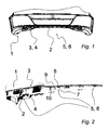
- the FIG. 1 shows an overview of a trim arrangement according to the invention for a motor vehicle in an interior view, ie in the later visible surface of the vehicle opposite side of view.
- the trim arrangement has a substantially thin-walled exterior attachment 1 made of plastic, which forms a bumper trim 1 in this case.
- the cladding arrangement has an inner part 2 reinforcing the structure of the outer attachment 1.
- the outer attachment 1 and the inner part 2 have at their edge regions 3, 4 each at least one connecting portion 5, 6 with integrally formed connecting means 7, 8, 9, 10 (not shown in detail here). By means of the connecting means 7, 8, 9, 10, the external attachment 1 and the inner part 2 are connected to one another.
- FIG. 2 shows a detailed overview of exterior attachment 1 and the outer component 1 reinforcing inner part 2, wherein the view represents an area that represents the internal bottom view of the outer attachment part 1 and the reinforcing inner part 2 when mounting the outer attachment to the vehicle.
- the cladding arrangement has a first connecting means pair 7, 8 consisting of a hook element 7 and a hook element receptacle 8 corresponding thereto.
- a second, functionally independent connecting means pair 9, 10 consists of a formation 9 and a shaping receptacle 10 corresponding thereto.
- the forming receptacle 10 is designed such that that in the connected state of the external attachment 1 and the inner part 2, the formation 9 is encompassed or enclosed at least in regions by the formation receptacle 10.
- the connecting means 7, 8, 9, 10 are coordinated so that the hook element 7 with the Hakenelementam 8 latching is connectable as soon as the shaping 9 encompassing or enclosing Ausformungsage 10 abuts the component on which the formation 9 is arranged - in this embodiment, this is the outer attachment 1.
- the formation 9 on the outer attachment 1 and the Ausformungsage 10 on the inner part 2 are integrally formed.
- the shaping receptacle 10 and the hook element receptacle 8 are formed like a strap. In the context of the invention, it is likewise conceivable to form the forming receptacle 10 and / or the hook element receptacle 8 in a bow-shaped or arcuate or bush-shaped or L-shaped or C-shaped manner.
- the exemplary embodiment shows at least two second connecting means pairs 9, 10, wherein the first connecting means pair 7, 8 is arranged between the second connecting means pairs 9, 10.
- the outer attachment 1 consists of a thermoplastic or a plastic alloy of polypropylene with ethylene-propylene-diene rubber and admixtures of talc.
- the outer attachment 1 has a wall thickness in the range of 2.0 mm to 4.0 mm, preferably from 2.5 mm to 3.5 mm, preferably from 2.8 mm to 3.2 mm.
- the external attachment 1 may also be a mudguard cover 1.
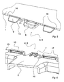
- FIG. 3 shows a detail of the cladding arrangement with a substantially thin-walled external attachment 1 made of plastic, an outer part 1 reinforcing the structure of the outer part 1, wherein the outer attachment 1 and the inner part 2 at the edge region 3, 4 each at least one connecting portion 5, 6 with integrally formed connecting means , 8, 9, 10, by means of which the outer attachment 1 and the inner part 2 are interconnected.
- a first pair of connecting means 7, 8 consists of a hook element 7 and a corresponding hook element receptacle 8.
- a second, functionally independent, connecting means pair 9, 10 consists of a molding 9 and a corresponding thereto forming receptacle 10.
- the Ausformungsage 10 is formed so that in the connected State of the outer attachment part 1 and inner part 2, the formation 9 is at least partially encompassed or enclosed by the shaping seat 10.
- the connecting means 7, 8, 9, 10 are coordinated so that the hook element 7 is latchingly connected to the hook element receptacle 8, as soon as the shaping 9 encompassing or enclosing Ausformungsage 10 rests against the component on which the formation 9 is arranged, wherein the formation 9 is arranged in this embodiment on the outer attachment part 1.
- FIG. 4 shows the already in FIG. 3 shown detail area of the lining arrangement according to the invention, in which case the in FIG. 3 hidden underside is shown.
- the formation 9 has a free end 15 to tapering wall thickness and a tapering towards the free end 15 in cross-section.
- the formation 9 has a cylindrical or pyramidal or conical or purely rectangular configuration. In this case, in particular in the case of a cylindrical or pyramidal or conical design towards the free end 15, a tapering diameter may be present.
- FIG. 5 As soon as the hook element 7, not shown here, of the inner part 2 is latchingly connected to the hook element receptacle 8, the forming receptacle 10 of the inner part 2, which is likewise not shown here, rests against the outer attachment part 1 in the region the contact surfaces 17, 18 at.
- FIG. 6 shows the inner part 2 with a shaping receptacle 10 and a hook element 7.
- the hook element 7 has a Aufgleitelement 16 on.
- wall thickness 11 of the formation 9 and the wall thickness shown here 13 of the shaping 9 encompassing or enclosing area 13 of the forming receptacle 10 are coordinated so that the wall thicknesses 11, 13 in the connected state taken together are at most as large as the wall thickness 14 (see FIG. 5) of the outer attachment 1 in the region of the connecting means 7, 8, 9, 10.
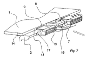
- FIG. 7 1 shows a lining arrangement according to the invention with a substantially thin-walled outer attachment 1 made of plastic and an inner part 2 reinforcing the structure of the outer attachment 1, wherein the outer attachment 1 and the inner part 2 at their edge region 3, 4 each have at least one connecting region 5, 6 with integrally formed connecting means 7, 8, 9, 10, by means of which the Au ⁇ enanbauteil 1 and the inner part 2 are connected to one another.
- the in FIG. 7 Arrow indicates the mounting direction of the inner part 2, wherein in this embodiment, the inner part 2 is pushed onto the outer attachment 1.
- the fairing arrangement has a first connecting means pair 7, 8 consisting of a hook element 7, which on the inner part 2 is formed and a corresponding thereto hook element holder 8, which is integrally formed on the outer attachment part 2.
- a second, functionally independent pair of connecting means 9, 10 is provided and consists of a molding 9, which is integrally formed on the outer attachment 2, and a corresponding thereto forming receptacle 10, which is integrally formed on the inner part 2.
- the shaping receptacle 10 is designed such that in the connected state of the outer attachment 1 and the inner part 2, the formation 9 is encompassed or enclosed at least in regions by the formation receptacle 10.
- the connecting means 7, 8, 9, 10 are coordinated so that the hook element 7 with the Hakenelementaid 8 latching is connectable as soon as the shaping 9 encompassing or enclosing Ausformungsage 10 abuts the component on which the formation 9 is arranged in
- the wall thickness 11 of the formation 9 and the wall thickness 13 of the shaping 9 encompassing or enclosing area of the forming receptacle 10 are coordinated so that the wall thicknesses 11, 13 in the connected state together are maximally as large as the wall thickness 14 of the outer attachment 1 in the region of the connecting means 7, 8, 9, 10.
- the formations 9 have a free end 15 towards tapering wall thickness.
- the shaping receptacle 10 and the hook element receptacle 8 are formed like a strap.
- the hook element 7 has a slide-on element 16, which ensures during assembly that the hook element holder 8 and / or the hook element 7 are pressed against each other elastically, which also facilitates assembly.
- the formations 9 are correspondingly formed so long that the Aufgleitvorgang of hook element 7 and hook element holder 8 then begins when the protrusions 9 already engage in the Ausformungsingn 10.
Landscapes
- Engineering & Computer Science (AREA)
- Mechanical Engineering (AREA)
- General Engineering & Computer Science (AREA)
- Body Structure For Vehicles (AREA)
- Vehicle Interior And Exterior Ornaments, Soundproofing, And Insulation (AREA)
Claims (11)
- Agencement d'habillage, en particulier pour un véhicule automobile, comprenant :- un composant rapporté extérieur (1) essentiellement à paroi mince en plastique,- une partie intérieure (2) renforçant la structure du composant rapporté extérieur (1)- le composant rapporté extérieur (1) et la partie intérieure (2) présentant au niveau de leur région de bord (3, 4) à chaque fois au moins une région de liaison (5, 6) avec des moyens de liaison (7, 8, 9, 10) de préférence façonnés, au moyen desquels le composant rapporté extérieur (1) et la partie intérieure (2) peuvent être connectés l'un à l'autre,- au moins une première paire de moyens de liaison (7, 8) étant prévue, constituée d'un élément de crochet (7) et d'un logement correspondant (8) pour l'élément de crochet, et- au moins en outre une deuxième paire de moyens de liaison fonctionnellement autonome (9, 10) étant prévue, constituée d'une formation (9) et d'un logement de formation correspondant (10),- le logement de formation (10) étant réalisé de telle sorte que dans l'état connecté du composant rapporté extérieur (1) et de la partie intérieure (2), la formation (9) soit saisie sur son pourtour ou entourée au moins en partie par le logement de formation (10), et- les moyens de liaison (7, 8, 9, 10) étant adaptés les uns aux autres de telle sorte que l'élément de crochet (7) puisse être connecté par encliquetage au logement (8) pour l'élément de crochet dès que le logement de formation (10) saisissant sur son pourtour ou entourant la formation (9) s'applique contre le composant sur lequel est disposée la formation (9),caractérisé en ce que l'épaisseur de paroi (11) de la formation (9) et l'épaisseur de paroi de la région (13) du logement de formation (10) saisissant sur son pourtour ou entourant la formation (9) sont adaptées l'une à l'autre de telle sorte que les épaisseurs de paroi (11, 13) prises ensemble dans l'état connecté soient au maximum aussi grandes que l'épaisseur de paroi (14) du composant rapporté extérieur (1) dans la région des moyens de liaison (7, 8, 9, 10).
- Agencement d'habillage selon la revendication 1, caractérisé en ce que la formation (9) est disposée sur le composant rapporté extérieur (1) et le logement de formation (10) est disposé sur la partie intérieure (2), de préférence de manière façonnée d'une seule pièce.
- Agencement d'habillage selon l'une quelconque des revendications précédentes, caractérisé en ce que la formation (9) est réalisée sous forme cylindrique ou pyramidale ou conique ou rectangulaire.
- Agencement d'habillage selon l'une quelconque des revendications précédentes, caractérisé en ce que la formation (9) présente une épaisseur de paroi diminuant vers l'extrémité libre (15) ou un diamètre diminuant vers l'extrémité libre (15) ou une section transversale diminuant vers l'extrémité libre (15).
- Agencement d'habillage selon l'une quelconque des revendications précédentes, caractérisé en ce que le logement de formation (10) et/ou le logement (8) pour l'élément de crochet sont réalisés sous forme d'étrier ou sous forme courbe ou sous forme de douille ou sous forme de patte ou en forme de L ou en forme de C.
- Agencement d'habillage selon l'une quelconque des revendications précédentes, caractérisé en ce qu'au moins deux deuxièmes paires de moyens de liaison (9, 10) sont prévues, la première paire de moyens de liaison (7, 8) étant disposée entre les deuxièmes paires de moyens de liaison (9, 10).
- Agencement d'habillage selon l'une quelconque des revendications précédentes, caractérisé en ce que l'élément de crochet (7) présente un élément de glissement (16).
- Agencement d'habillage selon l'une quelconque des revendications précédentes, caractérisé en ce que le composant rapporté extérieur (1) se compose d'un plastique thermoplastique ou d'un alliage de plastique, de préférence de polypropylène avec du caoutchouc éthylène-propylène-diène et de mélanges de talc.
- Agencement d'habillage selon l'une quelconque des revendications précédentes, caractérisé en ce que le composant rapporté extérieur (1) présente une épaisseur de paroi dans la plage de 2,0 mm à 4,0 mm, de préférence de 2,5 mm à 3,5 mm, de préférence de 2,8 mm à 3,2 mm.
- Agencement d'habillage selon l'une quelconque des revendications précédentes, caractérisé en ce que le composant rapporté extérieur (1) est un habillage de pare-chocs ou un habillage de garde-boue.
- Véhicule automobile comprenant un agencement d'habillage selon l'une quelconque des revendications 1 à 10.
Applications Claiming Priority (1)
| Application Number | Priority Date | Filing Date | Title |
|---|---|---|---|
| DE201020007764 DE202010007764U1 (de) | 2010-06-09 | 2010-06-09 | Verkleidungsanordnung für ein Kraftfahrzeug |
Publications (2)
| Publication Number | Publication Date |
|---|---|
| EP2394859A1 EP2394859A1 (fr) | 2011-12-14 |
| EP2394859B1 true EP2394859B1 (fr) | 2013-09-18 |
Family
ID=44654617
Family Applications (1)
| Application Number | Title | Priority Date | Filing Date |
|---|---|---|---|
| EP20110004572 Active EP2394859B1 (fr) | 2010-06-09 | 2011-06-06 | Agencement d'habillage pour un véhicule automobile |
Country Status (3)
| Country | Link |
|---|---|
| EP (1) | EP2394859B1 (fr) |
| DE (1) | DE202010007764U1 (fr) |
| ES (1) | ES2439324T3 (fr) |
Families Citing this family (2)
| Publication number | Priority date | Publication date | Assignee | Title |
|---|---|---|---|---|
| DE202012104988U1 (de) | 2012-12-20 | 2014-04-01 | Rehau Ag + Co | Bauteil für ein Fahrzeug sowie Verbindungsanordnung mit einem Bauteil |
| CN207005033U (zh) * | 2017-01-24 | 2018-02-13 | 市光法雷奥(佛山)汽车照明系统有限公司 | 连接组件 |
Family Cites Families (8)
| Publication number | Priority date | Publication date | Assignee | Title |
|---|---|---|---|---|
| US5699601A (en) * | 1995-08-30 | 1997-12-23 | Ford Motor Company | Snap tab fastener and disassembly tool therefor |
| FR2796020B1 (fr) * | 1999-07-06 | 2001-09-14 | Plastic Omnium Cie | Bandeau de pare-chocs et pare-chocs muni d'un tel bandeau |
| DE19943293C2 (de) * | 1999-09-10 | 2002-02-14 | Porsche Ag | Halteeinrichtung für einen Ultraschallwandler an einem Aussenteil eines Kraftfahrzeuges |
| DE10250392B4 (de) * | 2002-10-29 | 2004-12-09 | Decoma (Germany) Gmbh | Bauteil, insbesondere Stoßleiste, und System zu seiner Befestigung |
| DE102005021895B4 (de) * | 2005-05-06 | 2016-02-25 | Decoma (Germany) Gmbh | Frontstossfängerverkleidung |
| DE102007019935A1 (de) * | 2007-04-27 | 2008-11-06 | Daimler Ag | Befestigungsanordnung mit einem Stoßfänger und einem Kotflügel für ein Kraftfahrzeug |
| DE102007033313A1 (de) * | 2007-07-18 | 2009-01-22 | Daimler Ag | Stoßfänger für einen Personenkraftwagen |
| FR2921609B1 (fr) * | 2007-10-02 | 2010-04-30 | Faurecia Bloc Avant | Ensemble de carrosserie de vehicule automobile comprenant un panneau et un bandeau de protection rapporte muni d'un enjoliveur |
-
2010
- 2010-06-09 DE DE201020007764 patent/DE202010007764U1/de not_active Expired - Lifetime
-
2011
- 2011-06-06 EP EP20110004572 patent/EP2394859B1/fr active Active
- 2011-06-06 ES ES11004572T patent/ES2439324T3/es active Active
Also Published As
| Publication number | Publication date |
|---|---|
| DE202010007764U1 (de) | 2011-11-29 |
| EP2394859A1 (fr) | 2011-12-14 |
| ES2439324T3 (es) | 2014-01-22 |
Similar Documents
| Publication | Publication Date | Title |
|---|---|---|
| EP2069167B1 (fr) | Dispositif de fixation pour une conduite | |
| EP1784318B1 (fr) | Dispositif de montage de capteur | |
| DE102010053843A1 (de) | Verbindungsanordnung | |
| DE112014005668T5 (de) | Fahrzeuggliedanbringungsstruktur und Heckspoileranbringungsstruktur | |
| WO2013091779A2 (fr) | Entraînement de broche pour élément de réglage d'un véhicule automobile | |
| DE102012024653B4 (de) | Entkopplungselement | |
| DE102015110306A1 (de) | Elastisch gemittelte ausrichtsysteme und -verfahren | |
| DE19607572B4 (de) | Clip zur Befestigung von Rohren und dergleichen | |
| EP2054638B1 (fr) | Clip de fixation | |
| EP2242669A1 (fr) | Dispositif de fixation pour une ligne | |
| DE102014116753B4 (de) | Scharniersäulenbaugruppe mit einer inneren halterungswand | |
| EP2394859A1 (fr) | Agencement d'habillage pour un véhicule automobile | |
| EP3521643A1 (fr) | Système de fixation | |
| DE102006022382A1 (de) | Vorrichtung und Verfahren zur Befestigung eines Wischermotors an ein Wischergestänge | |
| DE102008023635B4 (de) | Tülle | |
| DE102011109180B4 (de) | Fußgängerschutzvorrichtung für einen unteren Stoßbereich einer Kraftfahrzeug-Frontstoßfängerverkleidung | |
| DE102010055953A1 (de) | Stoßfängeranordnung und Verfahren zum Herstellen einer solchen Stoßfängeranordnung | |
| WO1997028979A1 (fr) | Profile d'etancheite pour vehicule automobile | |
| DE10058998C1 (de) | Stoßfängereinheit eines Kraftfahrzeuges | |
| WO2011006458A1 (fr) | Vitre d'automobile pourvue d'un cadre profilé enrobé par injection pour la fixation à une carrosserie | |
| AT505005B1 (de) | Anordnung zum verbinden von bauteilen | |
| DE102019208927B4 (de) | Flexibles Andruckelement | |
| DE102014010368A1 (de) | Montageeinrichtung und Verfahren zum Montieren eines ersten Bauelements an einem zweiten Bauelement eines Kraftwagens, insbesondere eines Personenkraftwagens | |
| DE102005021165B4 (de) | Verkleidungsteil, insbesondere für ein Fahrzeug | |
| EP3711990B1 (fr) | Élément de liaison avec deux dispositifs de maintien indépendants |
Legal Events
| Date | Code | Title | Description |
|---|---|---|---|
| AK | Designated contracting states |
Kind code of ref document: A1 Designated state(s): AL AT BE BG CH CY CZ DE DK EE ES FI FR GB GR HR HU IE IS IT LI LT LU LV MC MK MT NL NO PL PT RO RS SE SI SK SM TR |
|
| AX | Request for extension of the european patent |
Extension state: BA ME |
|
| PUAI | Public reference made under article 153(3) epc to a published international application that has entered the european phase |
Free format text: ORIGINAL CODE: 0009012 |
|
| 17P | Request for examination filed |
Effective date: 20120314 |
|
| GRAP | Despatch of communication of intention to grant a patent |
Free format text: ORIGINAL CODE: EPIDOSNIGR1 |
|
| INTG | Intention to grant announced |
Effective date: 20130415 |
|
| GRAS | Grant fee paid |
Free format text: ORIGINAL CODE: EPIDOSNIGR3 |
|
| GRAA | (expected) grant |
Free format text: ORIGINAL CODE: 0009210 |
|
| AK | Designated contracting states |
Kind code of ref document: B1 Designated state(s): AL AT BE BG CH CY CZ DE DK EE ES FI FR GB GR HR HU IE IS IT LI LT LU LV MC MK MT NL NO PL PT RO RS SE SI SK SM TR |
|
| REG | Reference to a national code |
Ref country code: GB Ref legal event code: FG4D Free format text: NOT ENGLISH |
|
| REG | Reference to a national code |
Ref country code: CH Ref legal event code: EP |
|
| REG | Reference to a national code |
Ref country code: IE Ref legal event code: FG4D Free format text: LANGUAGE OF EP DOCUMENT: GERMAN |
|
| REG | Reference to a national code |
Ref country code: AT Ref legal event code: REF Ref document number: 632557 Country of ref document: AT Kind code of ref document: T Effective date: 20131015 |
|
| REG | Reference to a national code |
Ref country code: DE Ref legal event code: R096 Ref document number: 502011001343 Country of ref document: DE Effective date: 20131114 |
|
| REG | Reference to a national code |
Ref country code: ES Ref legal event code: FG2A Ref document number: 2439324 Country of ref document: ES Kind code of ref document: T3 Effective date: 20140122 |
|
| PG25 | Lapsed in a contracting state [announced via postgrant information from national office to epo] |
Ref country code: NO Free format text: LAPSE BECAUSE OF FAILURE TO SUBMIT A TRANSLATION OF THE DESCRIPTION OR TO PAY THE FEE WITHIN THE PRESCRIBED TIME-LIMIT Effective date: 20131218 Ref country code: HR Free format text: LAPSE BECAUSE OF FAILURE TO SUBMIT A TRANSLATION OF THE DESCRIPTION OR TO PAY THE FEE WITHIN THE PRESCRIBED TIME-LIMIT Effective date: 20130918 Ref country code: SE Free format text: LAPSE BECAUSE OF FAILURE TO SUBMIT A TRANSLATION OF THE DESCRIPTION OR TO PAY THE FEE WITHIN THE PRESCRIBED TIME-LIMIT Effective date: 20130918 Ref country code: LT Free format text: LAPSE BECAUSE OF FAILURE TO SUBMIT A TRANSLATION OF THE DESCRIPTION OR TO PAY THE FEE WITHIN THE PRESCRIBED TIME-LIMIT Effective date: 20130918 Ref country code: CY Free format text: LAPSE BECAUSE OF FAILURE TO SUBMIT A TRANSLATION OF THE DESCRIPTION OR TO PAY THE FEE WITHIN THE PRESCRIBED TIME-LIMIT Effective date: 20130731 |
|
| REG | Reference to a national code |
Ref country code: NL Ref legal event code: VDEP Effective date: 20130918 |
|
| REG | Reference to a national code |
Ref country code: LT Ref legal event code: MG4D |
|
| PG25 | Lapsed in a contracting state [announced via postgrant information from national office to epo] |
Ref country code: FI Free format text: LAPSE BECAUSE OF FAILURE TO SUBMIT A TRANSLATION OF THE DESCRIPTION OR TO PAY THE FEE WITHIN THE PRESCRIBED TIME-LIMIT Effective date: 20130918 Ref country code: LV Free format text: LAPSE BECAUSE OF FAILURE TO SUBMIT A TRANSLATION OF THE DESCRIPTION OR TO PAY THE FEE WITHIN THE PRESCRIBED TIME-LIMIT Effective date: 20130918 Ref country code: GR Free format text: LAPSE BECAUSE OF FAILURE TO SUBMIT A TRANSLATION OF THE DESCRIPTION OR TO PAY THE FEE WITHIN THE PRESCRIBED TIME-LIMIT Effective date: 20131219 Ref country code: RS Free format text: LAPSE BECAUSE OF FAILURE TO SUBMIT A TRANSLATION OF THE DESCRIPTION OR TO PAY THE FEE WITHIN THE PRESCRIBED TIME-LIMIT Effective date: 20130918 Ref country code: SI Free format text: LAPSE BECAUSE OF FAILURE TO SUBMIT A TRANSLATION OF THE DESCRIPTION OR TO PAY THE FEE WITHIN THE PRESCRIBED TIME-LIMIT Effective date: 20130918 |
|
| RIN2 | Information on inventor provided after grant (corrected) |
Inventor name: JAKOBS, HOLGER Inventor name: UHLIG, NICO |
|
| PG25 | Lapsed in a contracting state [announced via postgrant information from national office to epo] |
Ref country code: CY Free format text: LAPSE BECAUSE OF FAILURE TO SUBMIT A TRANSLATION OF THE DESCRIPTION OR TO PAY THE FEE WITHIN THE PRESCRIBED TIME-LIMIT Effective date: 20130918 |
|
| PG25 | Lapsed in a contracting state [announced via postgrant information from national office to epo] |
Ref country code: IS Free format text: LAPSE BECAUSE OF FAILURE TO SUBMIT A TRANSLATION OF THE DESCRIPTION OR TO PAY THE FEE WITHIN THE PRESCRIBED TIME-LIMIT Effective date: 20140118 Ref country code: EE Free format text: LAPSE BECAUSE OF FAILURE TO SUBMIT A TRANSLATION OF THE DESCRIPTION OR TO PAY THE FEE WITHIN THE PRESCRIBED TIME-LIMIT Effective date: 20130918 Ref country code: NL Free format text: LAPSE BECAUSE OF FAILURE TO SUBMIT A TRANSLATION OF THE DESCRIPTION OR TO PAY THE FEE WITHIN THE PRESCRIBED TIME-LIMIT Effective date: 20130918 Ref country code: SK Free format text: LAPSE BECAUSE OF FAILURE TO SUBMIT A TRANSLATION OF THE DESCRIPTION OR TO PAY THE FEE WITHIN THE PRESCRIBED TIME-LIMIT Effective date: 20130918 |
|
| PG25 | Lapsed in a contracting state [announced via postgrant information from national office to epo] |
Ref country code: PL Free format text: LAPSE BECAUSE OF FAILURE TO SUBMIT A TRANSLATION OF THE DESCRIPTION OR TO PAY THE FEE WITHIN THE PRESCRIBED TIME-LIMIT Effective date: 20130918 |
|
| REG | Reference to a national code |
Ref country code: DE Ref legal event code: R081 Ref document number: 502011001343 Country of ref document: DE Owner name: REHAU AG & CO, DE Free format text: FORMER OWNER: REHAU AG & CO, 95111 REHAU, DE Effective date: 20140429 Ref country code: DE Ref legal event code: R081 Ref document number: 502011001343 Country of ref document: DE Owner name: DAIMLER AG, DE Free format text: FORMER OWNER: REHAU AG & CO, 95111 REHAU, DE Effective date: 20140429 Ref country code: DE Ref legal event code: R081 Ref document number: 502011001343 Country of ref document: DE Owner name: REHAU AUTOMOTIVE SE & CO. KG, DE Free format text: FORMER OWNER: REHAU AG & CO, 95111 REHAU, DE Effective date: 20140429 |
|
| REG | Reference to a national code |
Ref country code: DE Ref legal event code: R097 Ref document number: 502011001343 Country of ref document: DE |
|
| PG25 | Lapsed in a contracting state [announced via postgrant information from national office to epo] |
Ref country code: PT Free format text: LAPSE BECAUSE OF FAILURE TO SUBMIT A TRANSLATION OF THE DESCRIPTION OR TO PAY THE FEE WITHIN THE PRESCRIBED TIME-LIMIT Effective date: 20140120 |
|
| RAP2 | Party data changed (patent owner data changed or rights of a patent transferred) |
Owner name: REHAU AG + CO Owner name: DAIMLER AG |
|
| PLBE | No opposition filed within time limit |
Free format text: ORIGINAL CODE: 0009261 |
|
| STAA | Information on the status of an ep patent application or granted ep patent |
Free format text: STATUS: NO OPPOSITION FILED WITHIN TIME LIMIT |
|
| 26N | No opposition filed |
Effective date: 20140619 |
|
| REG | Reference to a national code |
Ref country code: ES Ref legal event code: PC2A Owner name: DAIMLER AG Effective date: 20140919 |
|
| REG | Reference to a national code |
Ref country code: HU Ref legal event code: AG4A Ref document number: E020425 Country of ref document: HU |
|
| PG25 | Lapsed in a contracting state [announced via postgrant information from national office to epo] |
Ref country code: DK Free format text: LAPSE BECAUSE OF FAILURE TO SUBMIT A TRANSLATION OF THE DESCRIPTION OR TO PAY THE FEE WITHIN THE PRESCRIBED TIME-LIMIT Effective date: 20130918 |
|
| REG | Reference to a national code |
Ref country code: DE Ref legal event code: R097 Ref document number: 502011001343 Country of ref document: DE Effective date: 20140619 |
|
| REG | Reference to a national code |
Ref country code: GB Ref legal event code: 732E Free format text: REGISTERED BETWEEN 20141002 AND 20141008 |
|
| REG | Reference to a national code |
Ref country code: HU Ref legal event code: GB9C Owner name: DAIMLER AG, DE Free format text: FORMER OWNER(S): REHAU AG + CO, DE Ref country code: HU Ref legal event code: FH1C Free format text: FORMER REPRESENTATIVE(S): ERDELY PETER, DANUBIA SZABADALMI ES JOGI IRODA KFT., HU Representative=s name: DANUBIA SZABADALMI ES JOGI IRODA KFT., HU Ref country code: HU Ref legal event code: GB9C Owner name: REHAU AG + CO, DE Free format text: FORMER OWNER(S): REHAU AG + CO, DE |
|
| PG25 | Lapsed in a contracting state [announced via postgrant information from national office to epo] |
Ref country code: MC Free format text: LAPSE BECAUSE OF FAILURE TO SUBMIT A TRANSLATION OF THE DESCRIPTION OR TO PAY THE FEE WITHIN THE PRESCRIBED TIME-LIMIT Effective date: 20130918 Ref country code: LU Free format text: LAPSE BECAUSE OF FAILURE TO SUBMIT A TRANSLATION OF THE DESCRIPTION OR TO PAY THE FEE WITHIN THE PRESCRIBED TIME-LIMIT Effective date: 20140606 |
|
| REG | Reference to a national code |
Ref country code: CH Ref legal event code: PL |
|
| REG | Reference to a national code |
Ref country code: IE Ref legal event code: MM4A |
|
| PG25 | Lapsed in a contracting state [announced via postgrant information from national office to epo] |
Ref country code: LI Free format text: LAPSE BECAUSE OF NON-PAYMENT OF DUE FEES Effective date: 20140630 Ref country code: CH Free format text: LAPSE BECAUSE OF NON-PAYMENT OF DUE FEES Effective date: 20140630 Ref country code: IE Free format text: LAPSE BECAUSE OF NON-PAYMENT OF DUE FEES Effective date: 20140606 |
|
| PG25 | Lapsed in a contracting state [announced via postgrant information from national office to epo] |
Ref country code: MT Free format text: LAPSE BECAUSE OF FAILURE TO SUBMIT A TRANSLATION OF THE DESCRIPTION OR TO PAY THE FEE WITHIN THE PRESCRIBED TIME-LIMIT Effective date: 20130918 |
|
| PG25 | Lapsed in a contracting state [announced via postgrant information from national office to epo] |
Ref country code: SM Free format text: LAPSE BECAUSE OF FAILURE TO SUBMIT A TRANSLATION OF THE DESCRIPTION OR TO PAY THE FEE WITHIN THE PRESCRIBED TIME-LIMIT Effective date: 20130918 |
|
| REG | Reference to a national code |
Ref country code: FR Ref legal event code: PLFP Year of fee payment: 6 |
|
| PG25 | Lapsed in a contracting state [announced via postgrant information from national office to epo] |
Ref country code: RO Free format text: LAPSE BECAUSE OF FAILURE TO SUBMIT A TRANSLATION OF THE DESCRIPTION OR TO PAY THE FEE WITHIN THE PRESCRIBED TIME-LIMIT Effective date: 20130918 |
|
| PG25 | Lapsed in a contracting state [announced via postgrant information from national office to epo] |
Ref country code: BG Free format text: LAPSE BECAUSE OF FAILURE TO SUBMIT A TRANSLATION OF THE DESCRIPTION OR TO PAY THE FEE WITHIN THE PRESCRIBED TIME-LIMIT Effective date: 20130918 |
|
| PG25 | Lapsed in a contracting state [announced via postgrant information from national office to epo] |
Ref country code: TR Free format text: LAPSE BECAUSE OF FAILURE TO SUBMIT A TRANSLATION OF THE DESCRIPTION OR TO PAY THE FEE WITHIN THE PRESCRIBED TIME-LIMIT Effective date: 20130918 Ref country code: BE Free format text: LAPSE BECAUSE OF FAILURE TO SUBMIT A TRANSLATION OF THE DESCRIPTION OR TO PAY THE FEE WITHIN THE PRESCRIBED TIME-LIMIT Effective date: 20140630 |
|
| REG | Reference to a national code |
Ref country code: FR Ref legal event code: PLFP Year of fee payment: 7 |
|
| REG | Reference to a national code |
Ref country code: AT Ref legal event code: MM01 Ref document number: 632557 Country of ref document: AT Kind code of ref document: T Effective date: 20160606 |
|
| PGFP | Annual fee paid to national office [announced via postgrant information from national office to epo] |
Ref country code: IT Payment date: 20170531 Year of fee payment: 7 |
|
| PG25 | Lapsed in a contracting state [announced via postgrant information from national office to epo] |
Ref country code: AT Free format text: LAPSE BECAUSE OF NON-PAYMENT OF DUE FEES Effective date: 20160606 |
|
| PGFP | Annual fee paid to national office [announced via postgrant information from national office to epo] |
Ref country code: GB Payment date: 20170704 Year of fee payment: 7 |
|
| REG | Reference to a national code |
Ref country code: DE Ref legal event code: R081 Ref document number: 502011001343 Country of ref document: DE Owner name: REHAU AUTOMOTIVE SE & CO. KG, DE Free format text: FORMER OWNERS: DAIMLER AG, 70327 STUTTGART, DE; REHAU AG & CO, 95111 REHAU, DE Ref country code: DE Ref legal event code: R081 Ref document number: 502011001343 Country of ref document: DE Owner name: REHAU AG & CO, DE Free format text: FORMER OWNERS: DAIMLER AG, 70327 STUTTGART, DE; REHAU AG & CO, 95111 REHAU, DE |
|
| REG | Reference to a national code |
Ref country code: FR Ref legal event code: PLFP Year of fee payment: 8 |
|
| PG25 | Lapsed in a contracting state [announced via postgrant information from national office to epo] |
Ref country code: MK Free format text: LAPSE BECAUSE OF FAILURE TO SUBMIT A TRANSLATION OF THE DESCRIPTION OR TO PAY THE FEE WITHIN THE PRESCRIBED TIME-LIMIT Effective date: 20130918 |
|
| PG25 | Lapsed in a contracting state [announced via postgrant information from national office to epo] |
Ref country code: AL Free format text: LAPSE BECAUSE OF FAILURE TO SUBMIT A TRANSLATION OF THE DESCRIPTION OR TO PAY THE FEE WITHIN THE PRESCRIBED TIME-LIMIT Effective date: 20130918 |
|
| PGFP | Annual fee paid to national office [announced via postgrant information from national office to epo] |
Ref country code: ES Payment date: 20180701 Year of fee payment: 8 |
|
| GBPC | Gb: european patent ceased through non-payment of renewal fee |
Effective date: 20180606 |
|
| PG25 | Lapsed in a contracting state [announced via postgrant information from national office to epo] |
Ref country code: IT Free format text: LAPSE BECAUSE OF NON-PAYMENT OF DUE FEES Effective date: 20180606 Ref country code: GB Free format text: LAPSE BECAUSE OF NON-PAYMENT OF DUE FEES Effective date: 20180606 |
|
| PGFP | Annual fee paid to national office [announced via postgrant information from national office to epo] |
Ref country code: CZ Payment date: 20190426 Year of fee payment: 9 |
|
| PGFP | Annual fee paid to national office [announced via postgrant information from national office to epo] |
Ref country code: HU Payment date: 20190502 Year of fee payment: 9 Ref country code: FR Payment date: 20190604 Year of fee payment: 9 |
|
| REG | Reference to a national code |
Ref country code: ES Ref legal event code: FD2A Effective date: 20201027 |
|
| PG25 | Lapsed in a contracting state [announced via postgrant information from national office to epo] |
Ref country code: CZ Free format text: LAPSE BECAUSE OF NON-PAYMENT OF DUE FEES Effective date: 20200606 Ref country code: ES Free format text: LAPSE BECAUSE OF NON-PAYMENT OF DUE FEES Effective date: 20190607 |
|
| PG25 | Lapsed in a contracting state [announced via postgrant information from national office to epo] |
Ref country code: FR Free format text: LAPSE BECAUSE OF NON-PAYMENT OF DUE FEES Effective date: 20200630 Ref country code: HU Free format text: LAPSE BECAUSE OF NON-PAYMENT OF DUE FEES Effective date: 20200607 |
|
| REG | Reference to a national code |
Ref country code: DE Ref legal event code: R081 Ref document number: 502011001343 Country of ref document: DE Owner name: REHAU AUTOMOTIVE SE & CO. KG, DE Free format text: FORMER OWNER: REHAU AG & CO, 95111 REHAU, DE Ref country code: DE Ref legal event code: R081 Ref document number: 502011001343 Country of ref document: DE Owner name: RESRG AUTOMOTIVE SE & CO. KG, DE Free format text: FORMER OWNER: REHAU AG & CO, 95111 REHAU, DE |
|
| P01 | Opt-out of the competence of the unified patent court (upc) registered |
Effective date: 20230530 |
|
| PGFP | Annual fee paid to national office [announced via postgrant information from national office to epo] |
Ref country code: DE Payment date: 20250630 Year of fee payment: 15 |
|
| REG | Reference to a national code |
Ref country code: DE Ref legal event code: R081 Ref document number: 502011001343 Country of ref document: DE Owner name: RESRG AUTOMOTIVE SE & CO. KG, DE Free format text: FORMER OWNER: REHAU AUTOMOTIVE SE & CO. KG, 95111 REHAU, DE |