EP2394819A1 - Maintenance system for large-format inkjet printing machines - Google Patents
Maintenance system for large-format inkjet printing machines Download PDFInfo
- Publication number
- EP2394819A1 EP2394819A1 EP09839560A EP09839560A EP2394819A1 EP 2394819 A1 EP2394819 A1 EP 2394819A1 EP 09839560 A EP09839560 A EP 09839560A EP 09839560 A EP09839560 A EP 09839560A EP 2394819 A1 EP2394819 A1 EP 2394819A1
- Authority
- EP
- European Patent Office
- Prior art keywords
- thin plate
- ink
- supporting plate
- injectors
- plate
- Prior art date
- Legal status (The legal status is an assumption and is not a legal conclusion. Google has not performed a legal analysis and makes no representation as to the accuracy of the status listed.)
- Withdrawn
Links
- 238000012423 maintenance Methods 0.000 title claims abstract description 15
- 238000007641 inkjet printing Methods 0.000 title claims abstract description 12
- 230000009471 action Effects 0.000 claims abstract description 5
- 229910001220 stainless steel Inorganic materials 0.000 claims abstract description 5
- 239000010935 stainless steel Substances 0.000 claims abstract description 5
- 230000005294 ferromagnetic effect Effects 0.000 claims abstract description 4
- 238000004140 cleaning Methods 0.000 claims description 8
- 230000007246 mechanism Effects 0.000 claims description 3
- 238000000926 separation method Methods 0.000 claims description 2
- 238000002347 injection Methods 0.000 claims 1
- 239000007924 injection Substances 0.000 claims 1
- 239000000976 ink Substances 0.000 description 51
- 238000007639 printing Methods 0.000 description 6
- 239000003086 colorant Substances 0.000 description 4
- 238000001704 evaporation Methods 0.000 description 3
- 230000008020 evaporation Effects 0.000 description 3
- 230000005499 meniscus Effects 0.000 description 3
- 239000011324 bead Substances 0.000 description 2
- 230000000740 bleeding effect Effects 0.000 description 2
- 230000008859 change Effects 0.000 description 2
- 238000006073 displacement reaction Methods 0.000 description 2
- 238000001035 drying Methods 0.000 description 2
- 229920001971 elastomer Polymers 0.000 description 2
- 239000000806 elastomer Substances 0.000 description 2
- 238000000034 method Methods 0.000 description 2
- 230000037452 priming Effects 0.000 description 2
- 230000008569 process Effects 0.000 description 2
- 230000003134 recirculating effect Effects 0.000 description 2
- 238000007664 blowing Methods 0.000 description 1
- 239000011248 coating agent Substances 0.000 description 1
- 238000000576 coating method Methods 0.000 description 1
- 230000003750 conditioning effect Effects 0.000 description 1
- 238000010276 construction Methods 0.000 description 1
- 230000003247 decreasing effect Effects 0.000 description 1
- 239000000428 dust Substances 0.000 description 1
- 230000003628 erosive effect Effects 0.000 description 1
- 239000000835 fiber Substances 0.000 description 1
- 239000012530 fluid Substances 0.000 description 1
- 239000012535 impurity Substances 0.000 description 1
- 230000000670 limiting effect Effects 0.000 description 1
- 239000007788 liquid Substances 0.000 description 1
- 239000000463 material Substances 0.000 description 1
- 230000010355 oscillation Effects 0.000 description 1
- 230000000135 prohibitive effect Effects 0.000 description 1
- 238000010926 purge Methods 0.000 description 1
- 230000002829 reductive effect Effects 0.000 description 1
Images

Classifications
-
- B—PERFORMING OPERATIONS; TRANSPORTING
- B41—PRINTING; LINING MACHINES; TYPEWRITERS; STAMPS
- B41J—TYPEWRITERS; SELECTIVE PRINTING MECHANISMS, i.e. MECHANISMS PRINTING OTHERWISE THAN FROM A FORME; CORRECTION OF TYPOGRAPHICAL ERRORS
- B41J2/00—Typewriters or selective printing mechanisms characterised by the printing or marking process for which they are designed
- B41J2/005—Typewriters or selective printing mechanisms characterised by the printing or marking process for which they are designed characterised by bringing liquid or particles selectively into contact with a printing material
- B41J2/01—Ink jet
- B41J2/135—Nozzles
- B41J2/165—Prevention or detection of nozzle clogging, e.g. cleaning, capping or moistening for nozzles
- B41J2/16505—Caps, spittoons or covers for cleaning or preventing drying out
- B41J2/16508—Caps, spittoons or covers for cleaning or preventing drying out connected with the printer frame
- B41J2/16511—Constructions for cap positioning
-
- B—PERFORMING OPERATIONS; TRANSPORTING
- B41—PRINTING; LINING MACHINES; TYPEWRITERS; STAMPS
- B41J—TYPEWRITERS; SELECTIVE PRINTING MECHANISMS, i.e. MECHANISMS PRINTING OTHERWISE THAN FROM A FORME; CORRECTION OF TYPOGRAPHICAL ERRORS
- B41J2/00—Typewriters or selective printing mechanisms characterised by the printing or marking process for which they are designed
- B41J2/005—Typewriters or selective printing mechanisms characterised by the printing or marking process for which they are designed characterised by bringing liquid or particles selectively into contact with a printing material
- B41J2/01—Ink jet
- B41J2/135—Nozzles
- B41J2/165—Prevention or detection of nozzle clogging, e.g. cleaning, capping or moistening for nozzles
- B41J2/16585—Prevention or detection of nozzle clogging, e.g. cleaning, capping or moistening for nozzles for paper-width or non-reciprocating print heads
Definitions
- the present invention refers to a maintenance system for large format inkjet printing machines that allows carrying out all the cleaning operations of the print heads in order to maintain the lower base of the supporting plate of the print heads, whereon the injecting holes are mounted, under optimal conditions and so that their complexity does not make it prohibitive.
- the number of injectors of each head is usually a power of two (1, 2, 4, 8, 16, 32, 64, 128, 256, 512, etc.), these are further aligned and uniformly distributed in a plane defined as the base of the supporting plate, commonly called "injector platc”.
- Each one of the mentioned heads needs a system that maintains the plate, wherein the injector holes are housed, in optimal cleaning state so that the print quality is not affected.
- inkjet print heads operate maintaining the ink under a pressure below the ambient pressure, the ink being maintained in the injectors by the action of the meniscus formed by the surface tension of the ink. Frequently occurs that the meniscus of one or a few injectors is broken by sharp mechanical and/or hydraulic oscillations. This makes that the affected injector(s), take air and get unprimed.
- the ink pressure is usually made to be higher than that outside, so that a small amount of ink to fill all the way up to the injector hole flows.
- This pressure increase is performed by increasing the pressure of the ink and/or decreasing the external pressure by vacuum.
- the ink flows through the injector holes so that the ink remaining in the injectors is always renewed and maintains its properties even in the event that this contain a highly volatile component, evaporation of which can cause a change in its properties.
- the main problem that can arise is that the evaporation of some volatile component, and therefore the increase of the concentration of other components, which increases the viscosity of the ink so much as to block the injectors.
- the maintenance system could also be responsible for recirculating the ink during the downtime periods of the machine. In this case the system must be able to move a higher ink amount.
- the maintenance system can automatically change the fluid flowing through the print head, by having various circuits that are switched using solenoid valves. This can be useful to clean ink residues in the internal circuit of the heads and even for automatically changing the ink used.
- the maintenance system for large format inkjet machines object of the present invention has the print heads housed in a supporting plate and the injectors are protected by a thin plate, preferably made of ferromagnetic stainless steel, which is located in a recess on the lower face of said supporting plate. It acquires an arrangement parallel to the base or flat of the injectors and slides between two limiting positions. It is separated from said base between 0.1 mm and 2 mm.
- the thin plate is kept attached to the supporting plate by the action of some magnets, so that the thin plate can not be separated from the supporting plate although it can move over the plane on which it is, by actuating some external mechanism.
- the thin plate has grooves made therein, which are aligned in one of its end positions with the injectors, so that the print heads can perform their work without interference. At the other end position of the thin plate, the groove is completely blocked against the supporting plate.
- the supporting plate has one or more ducts that communicate with the housing of the heads through channels. In this way the ink spilled in the gap between the thin plate and the supporting plate can be collected.
- the ink spilled in said gap by the injectors is carried by the thin plate when this is moved due to the combination of surface tension of the ink and the surface energy of the thin plate and base, which make the ink to "wet" the thin plate but not the base.
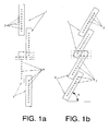
- the system maintenance for large format inkjet printing machines includes, as others of its type, different plates 1 for supporting the injectors 7 arranged in respective two different ways in order to print on each pass a larger width, i.e., a large format, leaving some overlapping areas between the supporting platens 1 so that injectors 7 make a uniform sweep.
- Figure 1a maintains the original resolution and Figure 1b increases since the sweep lines are closer together, with a factor equal to the inverse of the sine of "alpha".
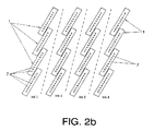
- the maintenance system proposed by the present invention consists or a thin plate 2 made of ferromagnetic stainless steel, has as many grooves 3 practiced therein as print heads 5 are installed in the module.
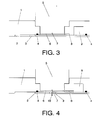
- the thin plate 2 can be moved between two end positions (shown respectively in Figures 3 and 4 ) and is held against the supporting plate 1 by the action of various magnets 4. These magnets 4 hold the thin plate 2 attached to the supporting plate 1 but allowing its displacement.
- the end position shown in Figure 3 is that corresponding to the inactivity phase, in which the thin plate 2 protects the print head 5 with the groove 3 blocked against the supporting plate 1.
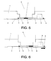
- the other end position corresponds to the printing phase, in which the thin plate 2 has been moved so that the grooves 3 are aligned with the injectors 7 of the print heads 5 allowing the injectors 7 to project the droplets 10 through the grooves 3.
- the thin plate 2 slides as indicated by the arrow in Figure 6 , dragging the ink 11 therewith.
Landscapes
- Ink Jet (AREA)
Applications Claiming Priority (2)
| Application Number | Priority Date | Filing Date | Title |
|---|---|---|---|
| ES200900358A ES2343830B1 (es) | 2009-02-09 | 2009-02-09 | Sistema de mantenimiento para maquinas de impresion por chorro de tinta, de gran formato. |
| PCT/ES2009/070503 WO2010089425A1 (es) | 2009-02-09 | 2009-11-17 | Sistema de mantenimiento para máquinas de impresión por chorro de tinta, de gran formato |
Publications (1)
| Publication Number | Publication Date |
|---|---|
| EP2394819A1 true EP2394819A1 (en) | 2011-12-14 |
Family
ID=42357321
Family Applications (1)
| Application Number | Title | Priority Date | Filing Date |
|---|---|---|---|
| EP09839560A Withdrawn EP2394819A1 (en) | 2009-02-09 | 2009-11-17 | Maintenance system for large-format inkjet printing machines |
Country Status (3)
| Country | Link |
|---|---|
| EP (1) | EP2394819A1 (es) |
| ES (1) | ES2343830B1 (es) |
| WO (1) | WO2010089425A1 (es) |
Families Citing this family (1)
| Publication number | Priority date | Publication date | Assignee | Title |
|---|---|---|---|---|
| ES2472140B2 (es) | 2014-02-07 | 2015-01-29 | Kerajet S.A. | Método de proyección de sólidos sobre una superficie |
Family Cites Families (6)
| Publication number | Priority date | Publication date | Assignee | Title |
|---|---|---|---|---|
| JPS5816855A (ja) * | 1981-07-24 | 1983-01-31 | Fuji Photo Film Co Ltd | インクジエツト用ノズルヘツド |
| JPH04115953A (ja) * | 1990-09-06 | 1992-04-16 | Seikosha Co Ltd | インクジェットプリンタ |
| JPH04251750A (ja) * | 1991-01-28 | 1992-09-08 | Fuji Electric Co Ltd | インクジェット記録ヘッド |
| JPH05177841A (ja) * | 1991-11-18 | 1993-07-20 | Fujitsu Ltd | インクジェットヘッド |
| JPH06340091A (ja) * | 1993-06-01 | 1994-12-13 | Ricoh Co Ltd | インクジェット記録装置 |
| JP3554099B2 (ja) * | 1996-02-13 | 2004-08-11 | キヤノン株式会社 | インクジェットプリント装置 |
-
2009
- 2009-02-09 ES ES200900358A patent/ES2343830B1/es not_active Expired - Fee Related
- 2009-11-17 WO PCT/ES2009/070503 patent/WO2010089425A1/es active Application Filing
- 2009-11-17 EP EP09839560A patent/EP2394819A1/en not_active Withdrawn
Non-Patent Citations (1)
| Title |
|---|
| See references of WO2010089425A1 * |
Also Published As
| Publication number | Publication date |
|---|---|
| ES2343830A1 (es) | 2010-08-10 |
| WO2010089425A1 (es) | 2010-08-12 |
| ES2343830B1 (es) | 2011-06-20 |
Similar Documents
| Publication | Publication Date | Title |
|---|---|---|
| US5117244A (en) | Nozzle capping device for an ink jet printhead | |
| US8678547B2 (en) | Inkjet recording device, inkjet recording method, and inkjet head cleaning device | |
| JP6344861B2 (ja) | 液体吐出装置及び液体吐出ヘッドの保湿装置 | |
| US10022972B2 (en) | Waste liquid container and attachment | |
| CN102099195A (zh) | 图像形成设备 | |
| JP2012143947A (ja) | 液体拭取りユニット及び液体噴射装置 | |
| CN113733761A (zh) | 一种双面喷墨打印机 | |
| CN106103826A (zh) | 记录装置和记录方法 | |
| US7357481B2 (en) | Duplex printing system capable of ink removal | |
| JP2016112766A (ja) | 印刷装置 | |
| JP2006247999A (ja) | 液体噴射装置および液体噴射装置におけるワイピング方法 | |
| EP2394819A1 (en) | Maintenance system for large-format inkjet printing machines | |
| DE60302278T2 (de) | Tintenstrahlkopf | |
| US9315027B1 (en) | Scalable printhead maintenance cart having maintenance modules | |
| US8376504B2 (en) | Fluid ejecting apparatus with humidification member for moisturing ink | |
| JP5470919B2 (ja) | 吸引装置およびこれを備えた液滴吐出装置 | |
| JP2008229932A (ja) | 液体吐出装置及びヘッドアセンブリ | |
| JP5732828B2 (ja) | インクジェット記録装置およびインクジェット記録装置のインクノズル面ワイピング方法 | |
| JP2008230100A (ja) | インクジェット記録装置 | |
| JP6606934B2 (ja) | 液体噴射装置 | |
| JP5104486B2 (ja) | 記録装置 | |
| JP2013169700A (ja) | 液体噴射ヘッド、および、液体噴射装置 | |
| US9156269B2 (en) | Liquid ejection apparatus | |
| JP2013071405A (ja) | インクジェット記録装置 | |
| JP7170492B2 (ja) | インクジェットプリンタ、インクジェットプリンタ印刷方法 |
Legal Events
| Date | Code | Title | Description |
|---|---|---|---|
| PUAI | Public reference made under article 153(3) epc to a published international application that has entered the european phase |
Free format text: ORIGINAL CODE: 0009012 |
|
| 17P | Request for examination filed |
Effective date: 20110608 |
|
| AK | Designated contracting states |
Kind code of ref document: A1 Designated state(s): AT BE BG CH CY CZ DE DK EE ES FI FR GB GR HR HU IE IS IT LI LT LU LV MC MK MT NL NO PL PT RO SE SI SK SM TR |
|
| DAX | Request for extension of the european patent (deleted) | ||
| STAA | Information on the status of an ep patent application or granted ep patent |
Free format text: STATUS: THE APPLICATION IS DEEMED TO BE WITHDRAWN |
|
| 18D | Application deemed to be withdrawn |
Effective date: 20130601 |