EP2391530B1 - Lenksteuersystem - Google Patents
Lenksteuersystem Download PDFInfo
- Publication number
- EP2391530B1 EP2391530B1 EP10706775.3A EP10706775A EP2391530B1 EP 2391530 B1 EP2391530 B1 EP 2391530B1 EP 10706775 A EP10706775 A EP 10706775A EP 2391530 B1 EP2391530 B1 EP 2391530B1
- Authority
- EP
- European Patent Office
- Prior art keywords
- worm screw
- piston
- valve
- steering
- channel
- Prior art date
- Legal status (The legal status is an assumption and is not a legal conclusion. Google has not performed a legal analysis and makes no representation as to the accuracy of the status listed.)
- Not-in-force
Links
- 239000012530 fluid Substances 0.000 claims description 37
- 230000033001 locomotion Effects 0.000 claims description 21
- 230000000712 assembly Effects 0.000 claims description 14
- 238000000429 assembly Methods 0.000 claims description 14
- 230000005540 biological transmission Effects 0.000 claims description 13
- 238000001514 detection method Methods 0.000 claims description 9
- 230000005355 Hall effect Effects 0.000 claims description 6
- 230000009471 action Effects 0.000 claims description 6
- 230000014759 maintenance of location Effects 0.000 claims description 5
- 238000004088 simulation Methods 0.000 claims description 5
- 239000010720 hydraulic oil Substances 0.000 claims description 4
- 238000013519 translation Methods 0.000 claims description 4
- 239000007788 liquid Substances 0.000 claims description 3
- 241000380131 Ammophila arenaria Species 0.000 claims description 2
- XUIMIQQOPSSXEZ-UHFFFAOYSA-N Silicon Chemical compound [Si] XUIMIQQOPSSXEZ-UHFFFAOYSA-N 0.000 claims description 2
- 238000013459 approach Methods 0.000 claims description 2
- 230000002457 bidirectional effect Effects 0.000 claims description 2
- 238000004891 communication Methods 0.000 claims description 2
- 230000006835 compression Effects 0.000 claims description 2
- 238000007906 compression Methods 0.000 claims description 2
- 230000008878 coupling Effects 0.000 claims description 2
- 238000010168 coupling process Methods 0.000 claims description 2
- 238000005859 coupling reaction Methods 0.000 claims description 2
- 230000000284 resting effect Effects 0.000 claims description 2
- 229910052710 silicon Inorganic materials 0.000 claims description 2
- 239000010703 silicon Substances 0.000 claims description 2
- 239000011295 pitch Substances 0.000 description 6
- 230000009467 reduction Effects 0.000 description 4
- 230000000694 effects Effects 0.000 description 3
- 238000007789 sealing Methods 0.000 description 3
- 230000008901 benefit Effects 0.000 description 2
- 238000006243 chemical reaction Methods 0.000 description 2
- 238000010586 diagram Methods 0.000 description 2
- 239000003921 oil Substances 0.000 description 2
- 238000012545 processing Methods 0.000 description 2
- 238000010521 absorption reaction Methods 0.000 description 1
- 230000003044 adaptive effect Effects 0.000 description 1
- 230000003466 anti-cipated effect Effects 0.000 description 1
- 230000000903 blocking effect Effects 0.000 description 1
- 210000004556 brain Anatomy 0.000 description 1
- 230000008859 change Effects 0.000 description 1
- 230000001143 conditioned effect Effects 0.000 description 1
- 230000003750 conditioning effect Effects 0.000 description 1
- 230000008030 elimination Effects 0.000 description 1
- 238000003379 elimination reaction Methods 0.000 description 1
- ZZUFCTLCJUWOSV-UHFFFAOYSA-N furosemide Chemical compound C1=C(Cl)C(S(=O)(=O)N)=CC(C(O)=O)=C1NCC1=CC=CO1 ZZUFCTLCJUWOSV-UHFFFAOYSA-N 0.000 description 1
- 238000004519 manufacturing process Methods 0.000 description 1
- 230000007246 mechanism Effects 0.000 description 1
- 230000001404 mediated effect Effects 0.000 description 1
- 238000000034 method Methods 0.000 description 1
- 239000000203 mixture Substances 0.000 description 1
- 238000012986 modification Methods 0.000 description 1
- 230000004048 modification Effects 0.000 description 1
- 238000013021 overheating Methods 0.000 description 1
- 229920001296 polysiloxane Polymers 0.000 description 1
- 238000012546 transfer Methods 0.000 description 1
- 238000004148 unit process Methods 0.000 description 1
Images




Classifications
-
- B—PERFORMING OPERATIONS; TRANSPORTING
- B62—LAND VEHICLES FOR TRAVELLING OTHERWISE THAN ON RAILS
- B62D—MOTOR VEHICLES; TRAILERS
- B62D5/00—Power-assisted or power-driven steering
- B62D5/001—Mechanical components or aspects of steer-by-wire systems, not otherwise provided for in this maingroup
- B62D5/005—Mechanical components or aspects of steer-by-wire systems, not otherwise provided for in this maingroup means for generating torque on steering wheel or input member, e.g. feedback
- B62D5/006—Mechanical components or aspects of steer-by-wire systems, not otherwise provided for in this maingroup means for generating torque on steering wheel or input member, e.g. feedback power actuated
-
- B—PERFORMING OPERATIONS; TRANSPORTING
- B63—SHIPS OR OTHER WATERBORNE VESSELS; RELATED EQUIPMENT
- B63H—MARINE PROPULSION OR STEERING
- B63H25/00—Steering; Slowing-down otherwise than by use of propulsive elements; Dynamic anchoring, i.e. positioning vessels by means of main or auxiliary propulsive elements
- B63H25/02—Initiating means for steering, for slowing down, otherwise than by use of propulsive elements, or for dynamic anchoring
-
- B—PERFORMING OPERATIONS; TRANSPORTING
- B63—SHIPS OR OTHER WATERBORNE VESSELS; RELATED EQUIPMENT
- B63H—MARINE PROPULSION OR STEERING
- B63H25/00—Steering; Slowing-down otherwise than by use of propulsive elements; Dynamic anchoring, i.e. positioning vessels by means of main or auxiliary propulsive elements
- B63H25/06—Steering by rudders
- B63H25/08—Steering gear
- B63H25/14—Steering gear power assisted; power driven, i.e. using steering engine
- B63H25/18—Transmitting of movement of initiating means to steering engine
-
- G—PHYSICS
- G09—EDUCATION; CRYPTOGRAPHY; DISPLAY; ADVERTISING; SEALS
- G09B—EDUCATIONAL OR DEMONSTRATION APPLIANCES; APPLIANCES FOR TEACHING, OR COMMUNICATING WITH, THE BLIND, DEAF OR MUTE; MODELS; PLANETARIA; GLOBES; MAPS; DIAGRAMS
- G09B9/00—Simulators for teaching or training purposes
- G09B9/02—Simulators for teaching or training purposes for teaching control of vehicles or other craft
-
- B—PERFORMING OPERATIONS; TRANSPORTING
- B63—SHIPS OR OTHER WATERBORNE VESSELS; RELATED EQUIPMENT
- B63H—MARINE PROPULSION OR STEERING
- B63H25/00—Steering; Slowing-down otherwise than by use of propulsive elements; Dynamic anchoring, i.e. positioning vessels by means of main or auxiliary propulsive elements
- B63H25/06—Steering by rudders
- B63H25/08—Steering gear
- B63H25/14—Steering gear power assisted; power driven, i.e. using steering engine
- B63H25/18—Transmitting of movement of initiating means to steering engine
- B63H25/22—Transmitting of movement of initiating means to steering engine by fluid means
-
- B—PERFORMING OPERATIONS; TRANSPORTING
- B63—SHIPS OR OTHER WATERBORNE VESSELS; RELATED EQUIPMENT
- B63H—MARINE PROPULSION OR STEERING
- B63H25/00—Steering; Slowing-down otherwise than by use of propulsive elements; Dynamic anchoring, i.e. positioning vessels by means of main or auxiliary propulsive elements
- B63H25/06—Steering by rudders
- B63H25/08—Steering gear
- B63H25/14—Steering gear power assisted; power driven, i.e. using steering engine
- B63H25/18—Transmitting of movement of initiating means to steering engine
- B63H25/24—Transmitting of movement of initiating means to steering engine by electrical means
Definitions
- the present invention relates to a drive control system.
- the invention concerns a system of the above kind particularly studied and realised to vary resistance of steering wheel, a rudder or like of a vehicle, such as a car, a boat, an aircraft and like, but also console of a video game or of simulation apparatus, the latter being always more frequently used in developing cars, modifying the feeling felt while driving a vehicle by a driver.
- steering systems have, on one side the aim of reducing the physical stress while controlling the vehicle in the different driving situations (for example power-steering for cars or hydro guide for trucks), and on the other side they should give a much more realistic control feeling, to give to the driver brain all the information about attitude and stability of the vehicle driven, in order to ensure maximum control and safety.
- Electric/electronic steering systems presently available on the nautical market - but also in the industrial field - implement DC brushless electric motors. Said systems are also provided with electronic control units (ECU) piloted by sophisticated software.
- ECU electronice control units
- Said brushless DC motors are directly mounted on the steering wheel support, in lieu of the steering wheel column, and can satisfy many driving comfort requisites. However, they do not always permit a realistic and comfortable guide in every manoeuvring situation.
- An advantage of this kind of systems is that of conferring a very fluid and continuous control and guide feeling, thanks to a purely mechanical control transmission, without mediation of electric systems.
- the driver is opposed to the torque generated by an active element, such as an electric motor.
- a steering control system for a car, a boat, an aircraft and like, or for a driving simulator, such as a videogame console, simulation apparatuses and like, said vehicle or simulator being provided with directioning means, said system comprising a direction control device, such as a steering wheel, a helm or like, comprising a steering column, detection means for detecting the position of said direction control device, an adjustment module having a frame, mechanically coupleable with said direction control device, preferably with said steering column, provided with actuator/adjustment means, by which it is capable of adjusting the resistance to the movement of said direction control device, one or more sensors for detecting the position of said directioning means, at least a central control unit, capable of calibrating the resistance against movement of said direction control device by said actuator/adjustment means, on the basis of the position of said direction control device detected by said detection means, and of controlling direction of said vehicle or simulator by said directioning means and said sensors, and a main worm screw and a lead nut engaged with
- said system could comprise at least one volumetric expansion chamber hydraulically connected with said chambers, said volumetric expansion chamber being capable of compensating volumetric expansion of said oily fluid at different environment or exercise temperatures, so as to obtain a uniform exercise pressure.
- said at least one volumetric expansion chamber for said container chambers could be provided with a piston and retention means, such as a preloaded spring, provided in such a way that, if a set inner pressure threshold is passed within said chambers when varying the outer temperature, said oily fluid therein flows within said volumetric expansion chamber making said piston retracting; if then temperature lower, said oily fluid returns from said volumetric expansion chamber to said container by the action of said piston and of said retention means.
- a piston and retention means such as a preloaded spring
- said first and said second chamber are delimited inside a main container, preferably a cylinder.
- said main worm screw and said lead nut could be of the sphere recirculation type or of the ground trapezoidal type.
- said actuator/adjustment means comprise at least one valve suitable to adjust oily fluid flow passing through said channel.
- said at least one valve could be of the On/Off type; and/or said at least one valve could be of the On/Off bidirectional type, and/or at least a valve could be of the proportional type, suitable to adjust the oily fluid flow partially passing through said channel; and/or it could comprise a valve of the opening/closure and proportional type; and/or it could comprise a gicleur and/or manually operated flow rate valve; and/or it could comprise a first valve of the proportional type and a second valve of the opening/closure (On/Off) type; and/or it could comprise a first valve of the one-way pressure proportional type to which a relevant not return valve is coupled in parallel, connected between said chamber and said channel, a second valve of the one-way pressure proportional type to which a relevant not return valve is coupled in parallel, connected between said chamber and said channel, and a volumetric expansion chamber, a volumetric compensation piston, sliding within said volumetric expansion chamber and a buckling spring connected with said volumetric compensation piston
- said main container could comprise valve seats on the surface for installing said valves.
- said actuator/adjustment means could comprise at least one gicleur and/or at least a manual adjustment flow rate valve.
- said oily fluid could be a hydraulic oil and/or ATF (Automatic Transmission Fluid) and/or silicon based liquid.
- said main worm screw could have a through longitudinal channel and comprises an inner projection within said through channel
- said steering column has an inner housing
- said adjustment module could comprise an adjustment shaft, in the intermediate portion of a circular projection and inserted within said longitudinal channel of said main worm screw, a first pre-loading ring nut, internally engaged by screwing with a first end of said adjustment shaft, and a second pre-loading ring nut, provided within said inner housing of the steering wheel column, said second pre-loading ring nut being integrally engaged by screwing with a portion close to a second end of said adjustment shaft by a threading inverse with respect to the threading of said first ring nut, aid first return spring and said first washer being coaxial with respect to said adjustment shaft between said first pre-loading ring nut and said circular projection, said washer being interposed between said first return spring and said circular projection, and said second return spring and said second washer being coaxial with respect to said adjustment shaft between said second pre-loading ring nut and said
- said main worm screw could have a longitudinal through channel and comprises an inner projection within said through channel
- said steering column has an inner housing
- said adjustment module could comprise a further worm screw, preferably a sphere recirculation worm screw, inserted within said longitudinal through channel of said main worm screw, a further lead nut, preferably a sphere recirculation worm screw, at least partially inserted within said worm screw, and engaged with the same, an electric motor, preferably a brushless motor, connected by an elastic coupling with said further worm screw and controlled by said control central unit, so that, when said steering column is rotated following the rotation of said direction control device, said electric motor exerts a return torque on the direction control device when operated by said control central unit.
- said further worm screw could have a pitch lower than the pitch of said main worm screw, preferably with a pitch ratio between 3,3 and 30.
- said system could comprise a compensation spring provided between said hollow piston and the frame of said adjustment module.
- said central control unit could control said actuator/adjustment means by modulated electric signals, preferably by PWM (Pulse-width Modulation) signals.
- PWM Pulse-width Modulation
- said central control unit could be a programmable unit, so as to permit different programs for calibration of resistance opposed to the movement of said device for controlling the direction, that can be selected by an user; said system being provided with interface means comprising means for selecting said programs and a control display.
- said detection means could comprise one or more dynamic angular sensors.
- said directing means could comprise one or more steering compartment piston - cylinder assemblies and one or more lifting piston - cylinder assemblies, respectively for controlling one or more nautical surface transmissions and actuation valves connected with said central control unit, for actuating said steering compartment piston - cylinder assemblies and of said lifting piston - cylinder assemblies.
- said system could comprise one or more sensors of the Hall effect type or of the magneto resistive type, suitable to detect the position of said steering compartment piston - cylinder assemblies and of said lifting piston - cylinder assemblies.
- said system can comprise one or more sensors of the Hall effect type or of the magneto resistive type, suitable to detect the position of said steering compartment piston - cylinder assemblies and of said lifting piston - cylinder assemblies.
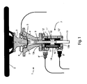
- FIG. 1 it is possible observing the section view of a system 1 for controlling driving of a vehicle (not shown in the figure), such as a boat or a car, according to the present invention.
- Steering wheel 2 is fixed to its own support 3, which is rotably coupled with a steering column 4 by sphere bearings 5.
- a dynamic angular sensor 6 is installed on said support, suitable to detect the position of the steering wheel 2, i.e. the rotation angle with respect to a reference position.
- Said dynamic angular sensor 6 is connected by an electric cable 6' with a central control unit (not shown in the figure), the function of which will be better described in the following.
- System 1 also provides a first embodiment of an adjustment module, indicated by reference number 7, mechanically connected with said steering wheel 2.
- Said adjustment module 7 is provided with actuating means 8', 8", by which it can adjust resistance to the steering wheel 2 rotation, thus varying according to the needing tactile feeling for controlling vehicle by the driver.
- said adjustment module 7 comprises a worm screw 8 or nut screw 9, fixed to said support 3 of the steering wheel 2, and engaged by threading with a lead nut 10.
- Adjustment module 7 also comprises a hollow piston 11, provided with a cylindrical seat 11', substantially in its intermediate portion, within which said lead nut 10 is housed.
- Said hollow piston 11 is placed within a main container or cylinder 12, of the double chamber or tandem type, comprised of two lids 12', 12", within which oil drainage screws are provided.
- Said seat 11' divides said main container 12 into two different chambers 13a and 13b, communicating by a channel 14.
- Said main container 12 is filled in with oily fluid, particularly hydraulic oil or ATF (Automatic Transmission Fluid) and/or with silicone based liquid and/or synthetic fluids.
- oily fluid particularly hydraulic oil or ATF (Automatic Transmission Fluid) and/or with silicone based liquid and/or synthetic fluids.
- said adjustment module 7 comprises a first and a second valve seats 15 and 16, wherein said actuating means are installed, said actuating means being comprised in the present embodiment with a first and a second valve 8' and 8". Said valves 8' and 8" are connected and controlled by said central control unit.
- said first valve 8' is of the proportional type and it is suitable to gradually close or to open said channel 14, while said second valve 8" is suitable to close or to open said channel (ON/OFF mode).
- Main container 12 can comprise, for each one of said chambers 13a and 13b, an outer expansion chamber (not shown in the figure), each one communicating with the relevant chamber 13a or 13b. This permits compensating expansion of said oily fluid with variation of the outer temperature.
- said further expansion chambers are provided with a piston and with retention means, such as a pre-loaded spring, provided in such a way that, in case the oily and/or synthetic fluid pressure passes a set threshold, part of the same fluid can transfer within said outer expansion chambers.
- retention means such as a pre-loaded spring
- Central control unit controls and manages vehicle directioning means, such as steering compartment piston - cylinder assembly and lifting piston - cylinder assembly for a nautical vehicle, or a rack or other actuating means for a car.
- vehicle directioning means such as steering compartment piston - cylinder assembly and lifting piston - cylinder assembly for a nautical vehicle, or a rack or other actuating means for a car.
- said central control unit can detect position of said directioning means by one or more position detection sensors.
- First proportional valve 8' or second ON/OFF valve 8" are connected to the on-board supply system and to the central control unit.
- Central control unit transmits a frequency signal, preferably a PWM (Pulse-Width Modulation) signal, to solenoid of one of valves 8' or 8", thus controlling position/diameter of the passage hole within the same valve.
- a frequency signal preferably a PWM (Pulse-Width Modulation) signal
- diameter of passage through channel 14, e.g. of the first proportional valve 8' is modified by a set minimum amount to a set maximum amount.
- valves 8', 8" introducing one gliceur only within channel 14. In this case, virtual end stroke effect cannot be obtained.
- Each configuration can provide to the manufacturer, but also to the vehicle driver, e.g. during sport races, possibility of choosing necessary force (torque) in order to rotate steering wheel 2.
- Dynamic angular sensor 6 transmits position of steering wheel 2 with respect to the zero position of the steering system, in real time to the central control unit, and said central control unit interacts with said first 8' and second 8" valves, and possibly with position transducers and/or with inclinometers integrated within the movable/mechanical/hydraulic portion of the system 1.
- control of said first 8' and second 8" valves being able hermetically closing passage of oil through channel 14 between chambers 13a and 13b, will guarantee "hydraulic stroke end" for steering wheel 2, when it has reached, according to one rotation direction, a set maximum angular value by the same software mapping.
- First proportional valve 8' or alternatively second ON/OFF valve 8" or alternatively gliceur of manual flow rate adjustment valve permit passage of oily fluid through channel 14 only when rotation direction of the steering wheel 2 is changed.
- central control unit calibrates resistance to movement of said direction control device 2, it adjusts at the same time, direction of motion of said vehicle by said directioning means.
- System 1 preferably also comprises a push button panel 17, such as the one shown in figure 2 , provided with push buttons 18 and with a selector 19, for choosing the different operative configurations 20 of the adjustment module 7 that can be programmed beforehand within the central control unit.
- a push button panel 17 such as the one shown in figure 2
- push buttons 18 and with a selector 19 for choosing the different operative configurations 20 of the adjustment module 7 that can be programmed beforehand within the central control unit.
- the system 1 according to the invention is very flexible.
- movements of the various parts involved can be also carried out by electric and/or hybrid actuators.
- Said electric and/or hybrid actuators can be controlled by an assembly of sensors and electronic units, in order to provide the most realistic control feeling.
- driving feeling will be realistically maintained, since it is mediated by hydraulic type means.
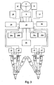
- FIG 3 shows the block diagram of connections of a control system for a nautical surface transmission pair 21 and 22.
- Each one of said surface transmissions 21 and 22 comprises a steering compartment piston - cylinder assembly 21', 22' and lifting piston - cylinder assembly 21", 22" as directioning means.
- central control unit 23 (ECU) is provided at the centre of the system 1, supplied by two supply batteries 24.
- Dynamic angular sensor 6 said first 8' and second 8" valves, and control valves 25a, 25b, 25c and 25d, for operation of said steering compartment piston - cylinder assembly 21', 22' and lifting piston - cylinder assembly 21", 22", are connected to the central control unit 23.
- central control unit 23 is connected to detection means, i.e. to the dynamic angular sensor 6, to the actuating means 8', 8", to sensors for detection of the position of directioning means and to the same directioning means.
- System 1 also comprises a hydraulic pump 26, connected and controlled by said central control unit 23, suitable to supply said steering compartment piston - cylinder assembly 21', 22' and lifting piston - cylinder assembly 21", 22".
- Hall effect sensors 27 are provided on surface transmissions 21 and 22, connected with said central control unit 23, each one suitable to detect position of said steering compartment piston - cylinder assembly 21', 22' and lifting piston - cylinder assembly 21", 22".
- this system 1 is also provided with a control display 28 and with a push button panel 17.
- system 1 permits different possibilities for adjusting hydraulic stroke end (before reaching mechanical stroke end) and to give operative "hardness" to the adjustable steering wheel 2.
- central control unit can, on the basis of the selected operative program of:
- a first example of adjustment program that can be implemented in the central control unit 23 and that can be particularly applied to the system configuration as shown in figure 3 , has the following requisites:
- central control unit 2 activates first proportional valve 8' and/or second ON/OFF valve 8"m closing the same simply cutting off electric supply of valve 8' or 8", as soon as steering wheel 2, or 180° rightward, or 180° leftward positions will be reached, i.e. positions that are recognised by central control unit 23.
- steering wheel 2 starting from position zero, cannot rotate beyond 180° according to each one of the rotation directions, which, in this final position, has reached its maximum set rotation angle, and thus its hydraulic stroke end (obviously not its mechanical stroke end).
- first proportional valve 8' (or second valve ON/OFF 8") directly mounted on main container 12 will close channel 14 as soon as maximum positions of the steering wheel 2, set 360° rightward or 360° leftward, are reached, and consequently recognised by central control unit 23.
- central control unit 23 activates hydraulic pump 26 and control valves 25a, 25b, 25c and 25d according to a set mode, acting directly on said steering compartment piston - cylinder assembly 21', 22' and lifting piston - cylinder assembly 21", 22".
- system 1 permits a feed-back acting not only on "steering wheel hardness", which is set by manufacture acting on software, but that can be also adjusted by the user using the interface means (display, keyboard/pushbuttons) with which it is possible tuning PWM frequency and thus the steering wheel rotation torque.
- interface means display, keyboard/pushbuttons
- this hardness can also evenly vary according to the different situations, such as geometrical reaching of the stroke end by a hub holder.
- system 1 would include one or more electro actuators acting as directioning means, connected with wheels, for example vehicle wheels, it could send to the central control unit 23, as additional information, current or power absorption by the operating activated device, or sending data packages, always to the control unit 23, acquired by using load cells (strength gauge) detecting inertia on connection levers and consequently adjusting proportional valve 8", reducing or increasing rotational torque necessary to operate steering wheel.
- load cells stress gauge
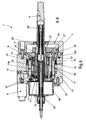
- Figures 4 and 5 show an assembly of the adjustment module 7' of the system for controlling the guide of a vehicle according to the present invention, which is really compact. Steering wheel column 4 can be observed from the figures.
- Steering column 4 is rotably placed by pins/spheres bearing 29 within housing 30.
- Lead nut 10 is of the sphere recirculation type and it is fixed within steering column 4 by tightening nut 31, so as to prevent rotation between said lead nut 10 and said column.
- Worm screw 9 is within the steering column 4.
- Piston 11 is fixed to the sphere recirculation worm screw 9 by a fixing nut 32.
- Central axis of piston 11 rotates symmetrically and it is positioned offset with respect to the central axis of the recirculation worm screw 9. This position prevents a rotation of the worm screw 9, thus making the latter translating only according to longitudinal axis direction.
- Piston 11 has housing 30 by its “pot” shape. Piston guide 33 and hydraulic sealings 34 are placed between housing 30 and piston 11. At the bottom, it is observed a housing 35 for valves 8 about piston 11, and first and second chambers, respectively 13a and 13b, are realised, that can create hydraulic pressure - independently each other - by hydraulic sealings 34.
- return springs 36' and 36" are provided inside the worm screw 9, which is hollow, with a longitudinal channel, as it is observed from figures, and of the steering column 4, which is hollow as well.
- Return springs 36' and 36" abut on one side against respective washers 37' and 37", which are provided spaced from the opposite sides on a circular projection 39' within the central portion of said worm screw 9.
- Return spring 36" has its other end abutting on preloading nut 38"; while return spring 36' has its other end abutting against preloading nut 38'.
- Said preloading nuts 38' and 38" are threaded on adjustment shaft 39.
- said preloading nut 38' has a leftward threading, and, as already said, it is coupled on the adjustment shaft, as well as screwed on spring seat lid.
- Return springs 36' and 36" and preloading nuts 38' and 38" are note engaged with inner walls of their seats. i.e. sphere recirculation worm screw 9 and steering column 4, thus permitting to the assembly to freely rotating about the return springs 36', 36", preloading nuts 38', 38" and adjustment shaft 39.
- the above spring 36' and 36" adjustment system permits to the manufacturer to individuate the most suitable active return pair. Particularly, once individuated the preferred pair, it is possible eliminating all the adjustable portion (nuts 38', 38", possibly adjustment shaft 39, ecc.) and inserting springs with a fixed adjustment.
- Integrated volumetric expansion chamber 41 is placed between valve seat 35 and cylindrical container 12.
- Said volumetric expansion chamber 41 is suitable to compensate volumetric expansion of hydraulic fluid at different environment or exercise temperatures (as it is well known, mechanical friction generates high temperature), so as to obtain a substantially always uniform exercise pressure.
- a volumetric compensation piston 42 is provided within volumetric expansion chamber 41, which is subjected to an elastic force developed by spring 43 directly acting on volumetric compensation piston 42.
- spring 43 directly acting on volumetric compensation piston 42.
- valve seat 35 two pressure proportional valves 8a and 8b and two one way valves 8a' and 8b', shown in figure 8 showing hydraulic scheme of steering actuator, and in figure 9 , showing a further section of the adjustment module 7', are provided.
- Steering shaft housing 30, cylindrical container 12 and housing 35 are assembled in such a way to create a single unit or assembly.
- Dynamic steering angular sensor(s) 6 are provided within flange 44.
- worm screw is operated by sphere recirculation lead nut 10, so as to translate along its longitudinal axis.
- Lead nut 10 is fixed to hollow piston 11, which is guided by cylindrical container 12 having a longitudinal axis not coincident with the rotation axis of lead nut 10.
- Pressure proportional valves 8a and 8a' permit maintaining constant the torque regardless fluid viscosity, and thus temperature.
- Said torque does not depend on the rotation speed of the steering column 4, as well as it is independent with respect to the hydraulic fluid thermal conditioning. Torque only depends on the electric current flow.
- system 1 does not require real time intervention of electronic/ECU - acting along with steering actuator - reading/detecting exact position of steering column 4 by dynamic angular sensor 6, in order to modify torque acting on steering column 4.
- These adjustments of relevant pressure proportional valves 8a, 8b can be anticipated by the following inversion of the rotation by a suitable software mapping. This would permit guaranteeing that wished return torque is always available, electronic cannot delay by valve piloting, it does not begin with piloting only during inversion of rotation, but anticipates the same.
- chambers 13a and 13b have different dimensions, this being due by the hollow piston 11 shape.
- Chamber 13a has a larger size than chamber 13b. Therefore, hydraulic fluid volume flowing following the reduction of chamber 13b volume is larger than chamber 13a volume, which increases at the same time.
- This volume difference remains within the volumetric expansion chamber 41. During the inversion of the steering column 4 rotation, this volume difference accumulated within the volumetric expansion chamber 41 again flows within the chamber 13b, the volume of which increases.
- Compressed return spring 36' or 36 on the basis of the steering wheel 2 rotation direction, exerts an "active" additional rotation torque, i.e. independent from action of the driver acting on steering wheel 2, aiming to make steering wheel returning to the 0° position.
- FIG. 10 shows section X-X of a third embodiment of adjustment module 7' that in this case is provided with steering wheel 2 return means, in this embodiment supplied electrically.
- Said adjustment module 7" comprises a further worm screw 45, of the sphere recirculation type, provided inside the sphere recirculation worm screw 9.
- Said further worm screw 45 is engaged with a further lead nut 46, which is of the sphere recirculation type. Said further lead nut 46 is at least partially inserted within and engaged with said worm screw 9.
- the further worm screw 45 is rotably housed within bearing 47, having its seat within the bearing 48 lid.
- An elastic joint 49 connects output shaft (not shown in figure) of an electric engine 50, preferably of the brushless type, mounted on a support 50' with a further worm screw 45.
- Worm screw 9 and 45 pitches define a transmission ratio between steering column 4 and electric motor 50.
- Electric motor 50 thanks to the above transmission ratio between said worm screw 9 and said further worm screw 45, as well as by the suitable programmable control of said central control unit 23 permits both exerting an "active" return torque on steering wheel 2, exactly as made by return springs 36' and 36" of the second embodiment, but in this case, said torque can be linear (as the action of a spring) or not linear, according to the programmable control of said central control unit 23, so as to realise any other driving simulation effect.
- Passive torques are hydraulically generated and act on steering column 4, and consequently on steering wheel 2, suitable to simulate high rotation torques that the driver expects finding during the driving when curving or during simulation of virtual stroke ends. In these cases it is possible simulating large torques with a very limited power.
- Brushless motor 50 and return springs 36' and 36" are particularly suitable to generate an active torque and can simulate/generate contrast torque on steering column 4.
- brushless electric motor 50 of the third embodiment of adjustment module 7" can generate adjustable high torques on steering column 4 in both the rotation directions.
Landscapes
- Engineering & Computer Science (AREA)
- Chemical & Material Sciences (AREA)
- Mechanical Engineering (AREA)
- Combustion & Propulsion (AREA)
- Ocean & Marine Engineering (AREA)
- Theoretical Computer Science (AREA)
- Physics & Mathematics (AREA)
- General Physics & Mathematics (AREA)
- Educational Technology (AREA)
- Educational Administration (AREA)
- Business, Economics & Management (AREA)
- Aviation & Aerospace Engineering (AREA)
- Transportation (AREA)
- Steering Control In Accordance With Driving Conditions (AREA)
- Control Of Vehicle Engines Or Engines For Specific Uses (AREA)
- Control Of Position Or Direction (AREA)
- Transmission Devices (AREA)
Claims (19)
- Lenksteuersystem (1), für ein Auto, ein Boot, ein Flugzeug und dergleichen, oder für einen Fahrsimulator, wie beispielsweise eine Videospielkonsole, Simulationsvorrichtungen und dergleichen, wobei das Fahrzeug oder der Simulator mit einer Richtungssteuerung (21', 22', 21", 22") ausgestattet sind,
wobei das System (1) umfasst:eine Richtungssteuereinrichtung (2), wie beispielsweise ein Lenkrad, ein Ruder oder dergleichen, umfassend eine Lenksäule (4),Erfassungsmittel (6) zur Erfassung der Position der Richtungssteuereinrichtung (2),ein Anpassungsmodul (7, 7', 7") mit einem Rahmen, mechanisch koppelbar mit der Richtungssteuereinrichtung (2), vorzugsweise mit der Lenksäule (4), das mit Stell-/Anpassungsmitteln (8', 8", 8a, 8a', 8b, 8b') versehen ist, durch die es in der Lage ist, den Widerstand gegen die Bewegung der Richtungssteuereinrichtung (2) anzupassen,einen oder mehrere Sensoren (27) zur Erfassung der Position der Richtungssteuerung (21', 22', 21", 22"),zumindest eine zentrale Steuereinheit (23), die in der Lage ist, den Widerstand gegen die Bewegung der Richtungssteuereinrichtung (2) durch die Stell-/Anpassungsmittel (8', 8", 8a, 8a', 8b, 8b') auf Basis der von dem Erfassungsmittel (6) erfassten Position der Richtungssteuereinrichtung (2) zu kalibrieren, und die in der Lage ist, die Richtung des Fahrzeugs oder Simulators durch die Richtungssteuerung und die Sensoren (27) zu steuern, undeine Hauptschneckenschraube (9) und eine Führungsmutter (10), die in Eingriff mit der Hauptschneckenschraube (9) ist,dadurch gekennzeichnet,dass das Anpassungsmodul (7, 7', 7") umfasst:eine erste und eine zweite Kammer (13a, 13b), die mit einem öligen Fluid ausgefüllt sind,die Lenksäule (4) der Steuereinrichtung (2) ist an der Führungsmutter (10) befestigt und die Hauptschneckenschraube (9) ist an dem Hohlkolben (11) befestigt, undeinen Hohlkolben (11), innerhalb dem die Hauptschneckenschraube (9) und die Führungsmutter (10) platziert sind, wobei der Hohlkolben (11) so eine Form aufweist, um die zwei Kammern (13a, 13b), die miteinander durch einen Kanal (14) in Verbindung stehen, abzugrenzen, so dass eine Bewegung der Hauptschneckenschraube (9) in Bezug auf die Führungsmutter (10) und vice versa eine Längsverschiebung des Hohlkolbens (11) erzeugt, wodurch das Volumen der Kammern (13a, 13b) verändert wird und das ölige Fluid, welches durch den Kanal (14) von einer Kammer (13a, 13b) zu der anderen (13b, 13a) läuft, verdrängt wird,dass die Stell-/Anpassungsmittel (8', 8", 8a, 8a', 8b, 8b') geeignet ausgebildet sind, um einen Fluss des öligen Fluids, das durch den Kanal (14) verläuft, anzupassen,dass die Lenksäule (4) der Steuereinrichtung (2) an der Führungsmutter (10) befestigt ist und die Hauptschneckenschraube (9) an dem Hohlkolben (11) befestigt ist, unddass das Anpassungsmodul (7') eine erste Rückstellfeder (36') und eine erste Scheibe (37'), und eine in Bezug auf die erste Rückstellfeder (36') gegenüberliegende zweite Rückstellfeder (36") und eine zweite Scheibe (37") umfasst, so dass wenn die Lenksäule (4), der Drehung der Richtungssteuereinrichtung (2) folgend, gedreht wird, die Hauptschneckenschraube (9) ein sich durch den Hohlkolben (11) veränderndes Volumen der Kammern (13a, 13b) umwandelt und alternativ mit einer der zwei Scheiben (37', 37") gemäß der Verschiebungsrichtung zusammenwirkt, wodurch die entsprechende Rückstellfeder (36', 36") zusammengedrückt wird, um ein Rückstellmoment auf die Lenksäule (4) zu erzeugen. - System (1) nach Anspruch 1, dadurch gekennzeichnet, dass es zumindest eine Volumenexpansionskammer (41) umfasst, die mit den Kammern (13a, 13b) hydraulisch verbunden ist, wobei die Volumenexpansionskammer (41) in der Lage ist, eine Volumenexpansion des öligen Fluids in unterschiedlichen Umgebungen oder Ausübungstemperaturen zu kompensieren, um einen gleichmäßigen Ausübungsdruck zu erhalten.
- System (1) nach Anspruch 2, dadurch gekennzeichnet, dass die zumindest eine Volumenexpansionskammer (41) für die Kammern (13a, 13b) mit einem Kolben (42) und Rückhaltemitteln (43), wie beispielsweise einer vorgespannten Feder, versehen ist, die derart bereitgestellt werden, dass wenn eine vorgegebene innere Druckgrenze innerhalb der Kammern (13a, 13b) bei der Veränderung der äußeren Temperatur überschritten wird, das ölige Fluid innerhalb der Volumenexpansionskammer (41) dort hineinfließt und ein Zurückfahren des Kolbens (42) veranlasst; wenn sich die Temperatur danach erniedrigt, kehrt das ölige Fluid von der Volumenexpansionskammer (41) zu dem Behälter (12) durch die Wirkung des Kolbens (42) und der Rückhaltemittel (43) zurück.
- System (1) nach einem der hervorgehenden Ansprüche, dadurch gekennzeichnet, dass die erste (13a) und die zweite (13b) Kammer im Innern eines Hauptbehälters (12), vorzugsweise einem Zylinder, abgegrenzt sind.
- System (1) nach einem der vorhergehenden Ansprüche, dadurch gekennzeichnet, dass die Hauptschneckenschraube (9) und die Führungsmutter (19) vom Kugelumlaufstyp oder vom geschliffenem Trapezgewindetyp sind.
- System (1) nach einem der hervorgehenden Ansprüche, dadurch gekennzeichnet, dass die Stell-/Anpassungsmittel (8', 8", 8a, 8a', 8b, 8b') zumindest ein Ventil (8', 8", 8a, 8a', 8b, 8b') umfassen, das geeignet ausgebildet ist, den durch den Kanal (14) verlaufenden Fluss des öligen Fluids anzupassen.
- System (1) nach Anspruch 6, dadurch gekennzeichnet, :- dass das zumindest eine Ventil (8') vom Ein/Aus-Typ ist; und/oder- dass das zumindest eine Ventil (8') vom Ein/Ausbidirektionalen Typ ist, und/oder- dass das zumindest eine Ventil (8") vom proportionalen Typ ist, das geeignet ausgebildet ist, um den Fluss des öligen Fluids, der teilweise durch den Kanal (14) verläuft, anzupassen; und/oder- dass es ein Ventil des Öffnungs/Schließungs- und Proportionaltyps umfasst; und/oder- dass es ein Gicleur-Ventil und/oder ein manuell betriebenes Durchflussmengenventil umfasst; und/oder- dass es ein erstes Ventil des Proportionaltyps (8') und ein zweites Ventil des Öffnungs/Schließungs (Ein/Aus)-Typs (8") umfasst; und/oder- dass es umfasst: ein erstes Ventil des Einweg-Druck-Proportionaltyps (8a), an dem ein relevantes Rückschlagventil (8a') parallel gekoppelt ist, verbunden zwischen der Kammer (13b) und dem Kanal (14), ein zweites Ventil vom Einweg-Druck-Proportionaltyp (8b), an dem ein relevantes Rückschlagventil (8b') parallel gekoppelt ist, verbunden zwischen der Kammer (13b) und dem Kanal (14), und eine Volumenexpansionskammer (41), einen Volumenausgleichskolben (42), der innerhalb der Volumenexpansionskammer (41) gleitet und eine Knickfeder (43), die mit dem Volumenausgleichskolben (42) verbunden ist.
- System (1) nach einem der Ansprüche 6 oder 7, wenn abhängig von Anspruch 4, dadurch gekennzeichnet, dass der Hauptbehälter (12) an der Oberfläche zur Installation der Ventile (8', 8", 8a, 8a', 8b, 8b') Ventilsitze (15, 16) umfasst.
- System (1) nach einem der vorhergehenden Ansprüche, dadurch gekennzeichnet, dass die Stell-/Anpassungsmittel (8', 8", 8a, 8a', 8b, 8b') zumindest ein Gicleur- und/oder zumindest ein manuelles Prüfungsanpassungsventil umfasst.
- System (1) nach einem der vorhergehenden Ansprüche, dadurch gekennzeichnet, dass das ölige Fluid ein Hydrauliköl und/oder ein ATF (Automatikgetriebeöl) und/oder eine silikonbasierte Flüssigkeit ist.
- System (1) nach einem der vorhergehenden Ansprüche, dadurch gekennzeichnet,
dass die Hauptschneckenschraube (9) einen durchgehenden Längskanal hat und einen inneren Vorsprung (9') innerhalb des durchgehenden Kanals umfasst,
dass die Lenksäule (4) ein inneres Gehäuse hat,
und dass das Anpassungsmodul (7') umfasst:eine Stellwelle (39), in dem Zwischenbereich eines kreisförmigen Vorsprungs (39') und eingeführt in den Längskanal der Hauptschneckenschraube (9),eine erste vorgespannte Ringmutter (38'), intern durch eine Verschraubung mit einem ersten Ende der Stellwelle (39) im Eingriff stehend, undeine innerhalb des inneren Gehäuses der Lenksäule (4) vorgesehene zweite vorgespannte Ringmutter (38"), wobei die zweite vorgespannte Ringmutter (38") durch eine Verschraubung mit einem Bereich nahe einem zweiten Ende der Stellwelle (39) durch ein Gewinde, das invers in Bezug auf das Gewinde der ersten Ringmutter (38') ist, fest im Eingriff steht,wobei die erste Rückstellfeder (36') und die erste Scheibe (37') koaxial in Bezug auf die Stellwelle (39) zwischen der ersten vorgespannten Ringmutter (38') und dem kreisförmigen Vorsprung (39') sind, wobei die Scheibe (37') zwischen der ersten Rückstellfeder (36') und dem kreisförmigen Vorsprung (39') eingefügt ist, undwobei die zweite Rückstellfeder (36") und die zweite Scheibe (37") koaxial in Bezug auf die Stellwelle (39) zwischen der zweiten vorgespannten Ringmutter (38") und dem kreisförmigen Vorsprung (39') sind, wobei die zweite Scheibe (37') zwischen der zweiten Rückstellfeder (36') und dem kreisförmigen Vorsprung (39') eingefügt ist,
so dass wenn die Stellwelle (39) gedreht wird, die vorgespannten Ringmuttern (38', 38") sich einander nähern oder sich voneinander entfernen und dadurch einen Druck der Rückstellfedern (36', 36") zwischen den gleichen Ringmuttern und dem kreisförmigen Vorsprung (39') anpassen undwenn die Lenksäule (4) infolge einer Drehung der Richtungssteuereinrichtung (2) gedreht wird, die Hauptschneckenschraube (9) ein sich durch den Hohlkolben (11) geändertes Volumen der Kammern (13a, 13b) bewegt und geeignet ausgebildet ist, um durch den inneren Vorsprung (9') mit einer Scheibe oder mit der anderen (37', 37") zusammen zu wirken, gemäß der Bewegungsrichtung, wobei die entsprechenden Rückstellfedern (36', 36") zusammengedrückt werden, um ein Rückstellmoment auf die Lenksäule (4) zu erzeugen, wobei die andere Scheibe auf den kreisförmigen Vorsprung (39') verbleibt. - System (1) nach Anspruch 11, dadurch gekennzeichnet, dass die Hauptschneckenschraube (9) einen länglichen Durchgangskanal hat und einen inneren Vorsprung (9') innerhalb dieses Durchgangskanals aufweist, und dass die Lenksäule (4) ein inneres Gehäuse hat, und dass
das Anpassungsmodul (7") umfasst:eine weitere Schneckenschraube (45), vorzugsweise eine Kugelumlaufschneckenschraube, die in den länglichen Durchgangskanal der Hauptschneckenschraube (9) eingeführt ist,eine weitere Führungsmutter (46), vorzugsweise eine Führungsmutter vom Kugelumlaufstyp, zumindest teilweise innerhalb der Schneckenschraube (9) eingeführt und im Eingriff mit dieser stehend,ein elektrischer Motor (50), vorzugsweise ein bürstenloser Motor, der über eine elastische Kupplung (49) mit der weiteren Schneckenschraube (45) verbunden ist und der durch eine zentrale Steuereinheit (23) gesteuert wird,so dass, wenn die Lenksäule (3) infolge einer Drehung der Richtungssteuereinrichtung (2) gedreht wird, der elektrische Motor (50) ein Rückstellmoment auf die Richtungssteuereinrichtung (2) ausübt, wenn er durch die zentrale Steuereinheit (23) betrieben wird. - System (1) nach Anspruch 12, dadurch gekennzeichnet, dass die weitere Schneckenschraube (25) eine Steigung aufweist die kleiner als die Steigung der Hauptschneckenschraube (9) ist, vorzugsweise in einem Steigungsverhältnis zwischen 3,3 und 30.
- System (1) nach einem der Ansprüche 12 oder 13, dadurch gekennzeichnet, dass es eine Kompensationsfeder (51) umfasst, die zwischen dem Hohlkolben (11) und dem Rahmen des Anpassungsmoduls (7") vorgesehen ist.
- System (1) nach einem der vorhergehenden Ansprüche, dadurch gekennzeichnet, dass die zentrale Steuereinheit (23) die Stell-/Anpassungsmittel (8', 8", 8a, 8a', 8b, 8b') durch modulierte elektrische Signale steuert, vorzugsweise durch PWM (Pulsweiten-Modulations)-Signale.
- System (1) nach einem der vorhergehenden Ansprüche, dadurch gekennzeichnet, dass die zentrale Steuereinheit (23) eine programmierbare Einheit ist, um unterschiedliche Programme, die von einem Benutzer ausgewählt werden können, für die Kalibrierung des Widerstands, entgegengesetzt zu der Bewegung der Einrichtung (2) zur Steuerung der Richtung, zu ermöglichen; wobei das System (1) mit Schnittstellenmittel (17) versehen ist, die Mittel (18, 19, 20) für die Auswahl dieser Programme und eine Steueranzeige (28) umfassen.
- System (1) nach einem der vorhergehenden Ansprüche, dadurch gekennzeichnet, dass die Erfassungsmittel einen oder mehrere dynamische Winkelsensoren (6) umfassen.
- System (1) nach einem der vorhergehenden Ansprüche, dadurch gekennzeichnet, dass die Lenkmittel einen oder mehrere Lenkfach-Kolben-Zylinderanordnungen (21', 22') und einen oder mehrere Hubkolben-Zylinder-Anordnungen (21", 22") umfassen, jeweils zur Steuerung einer oder mehrerer nautischer Oberflächengetriebe (21, 22) und Betätigungsventile (25a, 25b, 25c, und 25d), die mit der zentralen Steuereinheit (23) zur Betätigung der Lenkfach-Kolben-Zylinderanordnungen (21', 22') und der Hubkolben-Zylinder-Anordnungen (21", 22") verbunden sind.
- System (1) nach Anspruch 18, dadurch gekennzeichnet, dass es eine oder mehrere Sensoren (27) des Hall-Effekts-Typs oder des Magnetwiderstandstyps umfasst, die geeignet sind, um die Position der Lenkfach-Kolben-Zylinderanordnungen (21', 22') und der Hubkolben-Zylinder-Anordnungen (21", 22") zu erfassen.
Applications Claiming Priority (2)
| Application Number | Priority Date | Filing Date | Title |
|---|---|---|---|
| ITRM2009A000032A IT1392732B1 (it) | 2009-01-27 | 2009-01-27 | Sistema per il controllo della guida di un veicolo. |
| PCT/IT2010/000022 WO2010086890A1 (en) | 2009-01-27 | 2010-01-27 | Drive control system |
Publications (2)
| Publication Number | Publication Date |
|---|---|
| EP2391530A1 EP2391530A1 (de) | 2011-12-07 |
| EP2391530B1 true EP2391530B1 (de) | 2014-09-10 |
Family
ID=41328419
Family Applications (1)
| Application Number | Title | Priority Date | Filing Date |
|---|---|---|---|
| EP10706775.3A Not-in-force EP2391530B1 (de) | 2009-01-27 | 2010-01-27 | Lenksteuersystem |
Country Status (8)
| Country | Link |
|---|---|
| US (1) | US9004219B2 (de) |
| EP (1) | EP2391530B1 (de) |
| JP (1) | JP2012516262A (de) |
| CN (1) | CN102395504B (de) |
| CA (1) | CA2753465A1 (de) |
| IT (1) | IT1392732B1 (de) |
| SG (1) | SG173162A1 (de) |
| WO (1) | WO2010086890A1 (de) |
Families Citing this family (21)
| Publication number | Priority date | Publication date | Assignee | Title |
|---|---|---|---|---|
| JP5014898B2 (ja) * | 2007-06-29 | 2012-08-29 | Thk株式会社 | ドライブシミュレータ用ステアリング及びドライブシミュレータ |
| KR101022547B1 (ko) * | 2009-04-17 | 2011-03-16 | 현대모비스 주식회사 | 전동 조향 장치의 조향 복원 방법 |
| CN103068672B (zh) * | 2010-08-19 | 2015-09-30 | 日发美克株式会社 | 船外机的操舵装置 |
| DE102011117500A1 (de) * | 2011-11-02 | 2013-05-02 | GM Global Technology Operations LLC (n. d. Gesetzen des Staates Delaware) | Elektrische Begrenzung eines Lenkeinrichtungsstellweges |
| EP2631154A3 (de) * | 2012-02-27 | 2016-03-23 | Schaeffler Technologies AG & Co. KG | Vorrichtung zur Gabe eines haptisch erfahrbaren Signals auf eine Lenkwelle eines Fahrzeugs |
| DE102013014121A1 (de) * | 2013-08-23 | 2015-02-26 | Audi Ag | Lenkanschlag |
| KR102602957B1 (ko) * | 2016-12-09 | 2023-11-23 | 현대자동차주식회사 | 스티어 바이 와이어 시스템의 조향 반력장치 |
| US10960924B2 (en) | 2017-06-16 | 2021-03-30 | Toyota Research Institute, Inc. | Vehicle systems for adjusting resistance or sensitivity of steering wheels and/or accelerator pedals |
| CN107369355A (zh) * | 2017-09-11 | 2017-11-21 | 深圳市前海智鼎科技有限公司 | 一种汽车驾驶模拟器的方向盘力反馈装置及方法 |
| US10683030B2 (en) * | 2017-09-22 | 2020-06-16 | GM Global Technology Operations LLC | Fluid flow control mechanism for a steering wheel emulator |
| CN110155156B (zh) * | 2018-02-11 | 2020-12-08 | 华为技术有限公司 | 转向轴耦合控制系统、方法及装配方法 |
| JP7195951B2 (ja) * | 2019-01-29 | 2022-12-26 | 川崎重工業株式会社 | ロック機能付き移動装置 |
| JP7488632B2 (ja) * | 2019-02-14 | 2024-05-22 | 日立Astemo株式会社 | 操舵制御装置 |
| CN112569589A (zh) * | 2019-09-30 | 2021-03-30 | 比亚迪股份有限公司 | 车载游戏系统和车辆 |
| US11511841B2 (en) * | 2020-03-10 | 2022-11-29 | Steering Solutions Ip Holding Corporation | Electrically assisted hydraulic steering system |
| WO2022040703A1 (en) * | 2020-08-21 | 2022-02-24 | Philip Otto | Steering and throttle system for a jet boat |
| CN112498473A (zh) * | 2020-12-24 | 2021-03-16 | 河南护航实业股份有限公司 | 一种商用车电子方向机 |
| CN113506488B (zh) * | 2021-06-30 | 2023-04-04 | 青岛科技大学 | 一种用于帆船驾驶训练的模拟船舵装置 |
| DK4197885T3 (en) * | 2021-12-15 | 2026-03-30 | Danfoss Power Solutions Inc | Hydraulisk styresystem |
| KR102677815B1 (ko) * | 2022-02-07 | 2024-06-24 | 주식회사 대양솔루션 | 선박용 자동조타장치 |
| GB2622659B (en) * | 2022-09-20 | 2025-07-30 | Hu Jian | Automobile steering simulator |
Citations (1)
| Publication number | Priority date | Publication date | Assignee | Title |
|---|---|---|---|---|
| EP1911659A2 (de) * | 2006-10-13 | 2008-04-16 | Hitachi, Ltd. | Lenksystem |
Family Cites Families (18)
| Publication number | Priority date | Publication date | Assignee | Title |
|---|---|---|---|---|
| DE2005404A1 (de) * | 1970-02-06 | 1971-09-02 | Robert Bosch Gmbh, 7000 Stuttgart | Hydraulische Lenkung |
| AU555119B2 (en) * | 1982-03-17 | 1986-09-11 | Howard Martin Arneson | Inboard outboard drive |
| JPH0674564U (ja) * | 1993-03-30 | 1994-10-21 | 日野自動車工業株式会社 | 車両用パワーステアリング装置 |
| DE19546733C1 (de) * | 1995-12-14 | 1997-03-27 | Daimler Benz Ag | Hydraulische Servolenkung |
| DE19842066A1 (de) * | 1998-09-15 | 2000-03-23 | Daimler Chrysler Ag | Lenksystem für ein Fahrzeug |
| DE19859806B4 (de) * | 1998-12-23 | 2005-03-31 | Daimlerchrysler Ag | Lenksystem für Kraftfahrzeuge |
| US6138596A (en) * | 1999-09-22 | 2000-10-31 | Brunswick Corporation | Damped steering mechanism for a watercraft |
| US6535806B2 (en) * | 2001-01-30 | 2003-03-18 | Delphi Technologies, Inc. | Tactile feedback control for steer-by-wire systems |
| US20030150366A1 (en) * | 2002-02-13 | 2003-08-14 | Kaufmann Timothy W. | Watercraft steer-by-wire system |
| DE10307567A1 (de) * | 2003-02-22 | 2004-09-02 | Linde Ag | Lenkvorrichtung mit einem eine Lenkkraft erzeugenden Lenkkraftsimulator |
| DE10344662A1 (de) * | 2003-09-25 | 2005-05-04 | Cuadro Diogenes Perez | Hydraulisches Lenksystem für Kraftfahrzeuge |
| JP2007131231A (ja) * | 2005-11-11 | 2007-05-31 | Toyota Motor Corp | ステアリング操作装置 |
| JP2008024059A (ja) * | 2006-07-18 | 2008-02-07 | Jtekt Corp | 車両用操舵装置 |
| JP2008074367A (ja) * | 2006-09-25 | 2008-04-03 | Jtekt Corp | 車両用操舵装置 |
| JP5139151B2 (ja) * | 2007-05-30 | 2013-02-06 | ヤマハ発動機株式会社 | 航走制御装置およびそれを備えた船舶 |
| EP2045168B1 (de) * | 2007-10-05 | 2010-12-22 | CNH Italia S.p.A. | Hydraulisches Lenksystem für ein Fahrzeug |
| DE102008021973A1 (de) * | 2008-05-02 | 2009-11-05 | Bayerische Motoren Werke Aktiengesellschaft | Fahrzeug- Lenksystem der by-wire-Bauart |
| US8397858B2 (en) * | 2010-06-04 | 2013-03-19 | Eaton Corporation | Hydro-mechanical steering unit with integrated emergency steering capability |
-
2009
- 2009-01-27 IT ITRM2009A000032A patent/IT1392732B1/it active
-
2010
- 2010-01-27 WO PCT/IT2010/000022 patent/WO2010086890A1/en not_active Ceased
- 2010-01-27 EP EP10706775.3A patent/EP2391530B1/de not_active Not-in-force
- 2010-01-27 CA CA2753465A patent/CA2753465A1/en not_active Abandoned
- 2010-01-27 JP JP2011547068A patent/JP2012516262A/ja active Pending
- 2010-01-27 CN CN2010800114248A patent/CN102395504B/zh not_active Expired - Fee Related
- 2010-01-27 SG SG2011054293A patent/SG173162A1/en unknown
- 2010-07-27 US US13/138,274 patent/US9004219B2/en not_active Expired - Fee Related
Patent Citations (1)
| Publication number | Priority date | Publication date | Assignee | Title |
|---|---|---|---|---|
| EP1911659A2 (de) * | 2006-10-13 | 2008-04-16 | Hitachi, Ltd. | Lenksystem |
Also Published As
| Publication number | Publication date |
|---|---|
| EP2391530A1 (de) | 2011-12-07 |
| CN102395504B (zh) | 2013-12-04 |
| ITRM20090032A1 (it) | 2010-07-28 |
| WO2010086890A4 (en) | 2010-09-30 |
| JP2012516262A (ja) | 2012-07-19 |
| SG173162A1 (en) | 2011-08-29 |
| CN102395504A (zh) | 2012-03-28 |
| CA2753465A1 (en) | 2010-08-05 |
| US9004219B2 (en) | 2015-04-14 |
| IT1392732B1 (it) | 2012-03-16 |
| US20120125141A1 (en) | 2012-05-24 |
| WO2010086890A1 (en) | 2010-08-05 |
Similar Documents
| Publication | Publication Date | Title |
|---|---|---|
| US9004219B2 (en) | Drive control system | |
| EP3676156B1 (de) | Steer-by-wire lenksystem eines kraftfahrzeugs mit einem rückmeldeaktuator besitzend eines integrated mrf lagers | |
| US8714042B2 (en) | Controllable steering rack guide system and method | |
| EP1354787B1 (de) | Aktives Vorderrad-Lenkungs-Stellglied und Verfahren zum Steuern eines Fahrzeugs | |
| KR20010022460A (ko) | 닫힌 중앙 유압 파워스티어링 시스템 | |
| CN109533009A (zh) | 用于方向盘仿真器的流体流量控制机构 | |
| US10703408B2 (en) | Steering system having a pressure sensor | |
| KR19980043831A (ko) | 자동차의 동력조향장치 | |
| US20060175118A1 (en) | Power steering unit | |
| CN108657264B (zh) | 一种路感力矩模拟机构及车 | |
| KR20220027223A (ko) | 스티어링 필링 유닛을 구비한 조향 시스템 | |
| JP2017087785A (ja) | 操舵装置 | |
| US10053202B2 (en) | Marine electric power assist steering rack and pinion | |
| EP3089906B1 (de) | Hydraulisches servolenksystem für fahrzeug | |
| US4385493A (en) | Hydraulically assisted steering device | |
| JP3994045B2 (ja) | 流量制御装置 | |
| CN100441462C (zh) | 用于汽车的电子控制动力转向装置 | |
| KR20160064818A (ko) | 축방향 하중 조절장치 | |
| JP2004196044A (ja) | 車両用操舵装置 | |
| KR102947659B1 (ko) | 엠알댐핑유닛 및 이를 포함하는 스티어 바이 와이어의 햅틱장치 | |
| EP4406623B1 (de) | Trainingsgerät | |
| JP2013082359A (ja) | 後輪転舵装置の中立位置復帰装置 | |
| KR100469076B1 (ko) | 파워스티어링용 조타력 제어장치 | |
| KR20030030461A (ko) | 자동차의 페달장치 | |
| KR19980054037A (ko) | 파워스티어링 장치의 소음저감장치 |
Legal Events
| Date | Code | Title | Description |
|---|---|---|---|
| PUAI | Public reference made under article 153(3) epc to a published international application that has entered the european phase |
Free format text: ORIGINAL CODE: 0009012 |
|
| 17P | Request for examination filed |
Effective date: 20110824 |
|
| AK | Designated contracting states |
Kind code of ref document: A1 Designated state(s): AT BE BG CH CY CZ DE DK EE ES FI FR GB GR HR HU IE IS IT LI LT LU LV MC MK MT NL NO PL PT RO SE SI SK SM TR |
|
| DAX | Request for extension of the european patent (deleted) | ||
| 17Q | First examination report despatched |
Effective date: 20120516 |
|
| REG | Reference to a national code |
Ref country code: DE Ref legal event code: R079 Ref document number: 602010018855 Country of ref document: DE Free format text: PREVIOUS MAIN CLASS: B62D0005000000 Ipc: B63H0025140000 |
|
| GRAP | Despatch of communication of intention to grant a patent |
Free format text: ORIGINAL CODE: EPIDOSNIGR1 |
|
| INTG | Intention to grant announced |
Effective date: 20140131 |
|
| RIC1 | Information provided on ipc code assigned before grant |
Ipc: B63H 25/18 20060101ALI20140117BHEP Ipc: B63H 25/14 20060101AFI20140117BHEP Ipc: B63H 25/02 20060101ALI20140117BHEP Ipc: G09B 9/02 20060101ALI20140117BHEP Ipc: B63H 25/24 20060101ALI20140117BHEP Ipc: B62D 5/00 20060101ALI20140117BHEP Ipc: B63H 25/22 20060101ALI20140117BHEP |
|
| GRAS | Grant fee paid |
Free format text: ORIGINAL CODE: EPIDOSNIGR3 |
|
| GRAP | Despatch of communication of intention to grant a patent |
Free format text: ORIGINAL CODE: EPIDOSNIGR1 |
|
| GRAA | (expected) grant |
Free format text: ORIGINAL CODE: 0009210 |
|
| INTG | Intention to grant announced |
Effective date: 20140723 |
|
| RIN1 | Information on inventor provided before grant (corrected) |
Inventor name: ROSENMAIER, PETER Inventor name: KLINDWORTH, JAN |
|
| AK | Designated contracting states |
Kind code of ref document: B1 Designated state(s): AT BE BG CH CY CZ DE DK EE ES FI FR GB GR HR HU IE IS IT LI LT LU LV MC MK MT NL NO PL PT RO SE SI SK SM TR |
|
| REG | Reference to a national code |
Ref country code: GB Ref legal event code: FG4D |
|
| REG | Reference to a national code |
Ref country code: CH Ref legal event code: EP |
|
| REG | Reference to a national code |
Ref country code: IE Ref legal event code: FG4D |
|
| REG | Reference to a national code |
Ref country code: AT Ref legal event code: REF Ref document number: 686539 Country of ref document: AT Kind code of ref document: T Effective date: 20141015 |
|
| REG | Reference to a national code |
Ref country code: DE Ref legal event code: R096 Ref document number: 602010018855 Country of ref document: DE Effective date: 20141023 |
|
| PG25 | Lapsed in a contracting state [announced via postgrant information from national office to epo] |
Ref country code: ES Free format text: LAPSE BECAUSE OF FAILURE TO SUBMIT A TRANSLATION OF THE DESCRIPTION OR TO PAY THE FEE WITHIN THE PRESCRIBED TIME-LIMIT Effective date: 20140910 Ref country code: GR Free format text: LAPSE BECAUSE OF FAILURE TO SUBMIT A TRANSLATION OF THE DESCRIPTION OR TO PAY THE FEE WITHIN THE PRESCRIBED TIME-LIMIT Effective date: 20141211 Ref country code: FI Free format text: LAPSE BECAUSE OF FAILURE TO SUBMIT A TRANSLATION OF THE DESCRIPTION OR TO PAY THE FEE WITHIN THE PRESCRIBED TIME-LIMIT Effective date: 20140910 Ref country code: SE Free format text: LAPSE BECAUSE OF FAILURE TO SUBMIT A TRANSLATION OF THE DESCRIPTION OR TO PAY THE FEE WITHIN THE PRESCRIBED TIME-LIMIT Effective date: 20140910 Ref country code: LT Free format text: LAPSE BECAUSE OF FAILURE TO SUBMIT A TRANSLATION OF THE DESCRIPTION OR TO PAY THE FEE WITHIN THE PRESCRIBED TIME-LIMIT Effective date: 20140910 Ref country code: NO Free format text: LAPSE BECAUSE OF FAILURE TO SUBMIT A TRANSLATION OF THE DESCRIPTION OR TO PAY THE FEE WITHIN THE PRESCRIBED TIME-LIMIT Effective date: 20141210 |
|
| REG | Reference to a national code |
Ref country code: NL Ref legal event code: VDEP Effective date: 20140910 |
|
| REG | Reference to a national code |
Ref country code: LT Ref legal event code: MG4D |
|
| PG25 | Lapsed in a contracting state [announced via postgrant information from national office to epo] |
Ref country code: HR Free format text: LAPSE BECAUSE OF FAILURE TO SUBMIT A TRANSLATION OF THE DESCRIPTION OR TO PAY THE FEE WITHIN THE PRESCRIBED TIME-LIMIT Effective date: 20140910 Ref country code: LV Free format text: LAPSE BECAUSE OF FAILURE TO SUBMIT A TRANSLATION OF THE DESCRIPTION OR TO PAY THE FEE WITHIN THE PRESCRIBED TIME-LIMIT Effective date: 20140910 Ref country code: CY Free format text: LAPSE BECAUSE OF FAILURE TO SUBMIT A TRANSLATION OF THE DESCRIPTION OR TO PAY THE FEE WITHIN THE PRESCRIBED TIME-LIMIT Effective date: 20140910 |
|
| REG | Reference to a national code |
Ref country code: AT Ref legal event code: MK05 Ref document number: 686539 Country of ref document: AT Kind code of ref document: T Effective date: 20140910 |
|
| PG25 | Lapsed in a contracting state [announced via postgrant information from national office to epo] |
Ref country code: NL Free format text: LAPSE BECAUSE OF FAILURE TO SUBMIT A TRANSLATION OF THE DESCRIPTION OR TO PAY THE FEE WITHIN THE PRESCRIBED TIME-LIMIT Effective date: 20140910 |
|
| PG25 | Lapsed in a contracting state [announced via postgrant information from national office to epo] |
Ref country code: PT Free format text: LAPSE BECAUSE OF FAILURE TO SUBMIT A TRANSLATION OF THE DESCRIPTION OR TO PAY THE FEE WITHIN THE PRESCRIBED TIME-LIMIT Effective date: 20150112 Ref country code: SK Free format text: LAPSE BECAUSE OF FAILURE TO SUBMIT A TRANSLATION OF THE DESCRIPTION OR TO PAY THE FEE WITHIN THE PRESCRIBED TIME-LIMIT Effective date: 20140910 Ref country code: CZ Free format text: LAPSE BECAUSE OF FAILURE TO SUBMIT A TRANSLATION OF THE DESCRIPTION OR TO PAY THE FEE WITHIN THE PRESCRIBED TIME-LIMIT Effective date: 20140910 Ref country code: RO Free format text: LAPSE BECAUSE OF FAILURE TO SUBMIT A TRANSLATION OF THE DESCRIPTION OR TO PAY THE FEE WITHIN THE PRESCRIBED TIME-LIMIT Effective date: 20140910 Ref country code: IS Free format text: LAPSE BECAUSE OF FAILURE TO SUBMIT A TRANSLATION OF THE DESCRIPTION OR TO PAY THE FEE WITHIN THE PRESCRIBED TIME-LIMIT Effective date: 20150110 Ref country code: EE Free format text: LAPSE BECAUSE OF FAILURE TO SUBMIT A TRANSLATION OF THE DESCRIPTION OR TO PAY THE FEE WITHIN THE PRESCRIBED TIME-LIMIT Effective date: 20140910 |
|
| PGFP | Annual fee paid to national office [announced via postgrant information from national office to epo] |
Ref country code: IT Payment date: 20150129 Year of fee payment: 6 |
|
| PG25 | Lapsed in a contracting state [announced via postgrant information from national office to epo] |
Ref country code: AT Free format text: LAPSE BECAUSE OF FAILURE TO SUBMIT A TRANSLATION OF THE DESCRIPTION OR TO PAY THE FEE WITHIN THE PRESCRIBED TIME-LIMIT Effective date: 20140910 Ref country code: PL Free format text: LAPSE BECAUSE OF FAILURE TO SUBMIT A TRANSLATION OF THE DESCRIPTION OR TO PAY THE FEE WITHIN THE PRESCRIBED TIME-LIMIT Effective date: 20140910 |
|
| REG | Reference to a national code |
Ref country code: DE Ref legal event code: R097 Ref document number: 602010018855 Country of ref document: DE |
|
| PG25 | Lapsed in a contracting state [announced via postgrant information from national office to epo] |
Ref country code: BE Free format text: LAPSE BECAUSE OF NON-PAYMENT OF DUE FEES Effective date: 20150131 |
|
| PLBE | No opposition filed within time limit |
Free format text: ORIGINAL CODE: 0009261 |
|
| STAA | Information on the status of an ep patent application or granted ep patent |
Free format text: STATUS: NO OPPOSITION FILED WITHIN TIME LIMIT |
|
| PG25 | Lapsed in a contracting state [announced via postgrant information from national office to epo] |
Ref country code: DK Free format text: LAPSE BECAUSE OF FAILURE TO SUBMIT A TRANSLATION OF THE DESCRIPTION OR TO PAY THE FEE WITHIN THE PRESCRIBED TIME-LIMIT Effective date: 20140910 |
|
| 26N | No opposition filed |
Effective date: 20150611 |
|
| REG | Reference to a national code |
Ref country code: CH Ref legal event code: PL |
|
| PG25 | Lapsed in a contracting state [announced via postgrant information from national office to epo] |
Ref country code: LU Free format text: LAPSE BECAUSE OF FAILURE TO SUBMIT A TRANSLATION OF THE DESCRIPTION OR TO PAY THE FEE WITHIN THE PRESCRIBED TIME-LIMIT Effective date: 20150127 |
|
| PG25 | Lapsed in a contracting state [announced via postgrant information from national office to epo] |
Ref country code: MC Free format text: LAPSE BECAUSE OF FAILURE TO SUBMIT A TRANSLATION OF THE DESCRIPTION OR TO PAY THE FEE WITHIN THE PRESCRIBED TIME-LIMIT Effective date: 20140910 |
|
| PG25 | Lapsed in a contracting state [announced via postgrant information from national office to epo] |
Ref country code: LI Free format text: LAPSE BECAUSE OF NON-PAYMENT OF DUE FEES Effective date: 20150131 Ref country code: CH Free format text: LAPSE BECAUSE OF NON-PAYMENT OF DUE FEES Effective date: 20150131 |
|
| REG | Reference to a national code |
Ref country code: IE Ref legal event code: MM4A |
|
| PG25 | Lapsed in a contracting state [announced via postgrant information from national office to epo] |
Ref country code: SI Free format text: LAPSE BECAUSE OF FAILURE TO SUBMIT A TRANSLATION OF THE DESCRIPTION OR TO PAY THE FEE WITHIN THE PRESCRIBED TIME-LIMIT Effective date: 20140910 |
|
| REG | Reference to a national code |
Ref country code: FR Ref legal event code: PLFP Year of fee payment: 7 |
|
| PG25 | Lapsed in a contracting state [announced via postgrant information from national office to epo] |
Ref country code: IE Free format text: LAPSE BECAUSE OF NON-PAYMENT OF DUE FEES Effective date: 20150127 |
|
| PGFP | Annual fee paid to national office [announced via postgrant information from national office to epo] |
Ref country code: FR Payment date: 20151223 Year of fee payment: 7 |
|
| PGFP | Annual fee paid to national office [announced via postgrant information from national office to epo] |
Ref country code: DE Payment date: 20160119 Year of fee payment: 7 |
|
| PGFP | Annual fee paid to national office [announced via postgrant information from national office to epo] |
Ref country code: GB Payment date: 20160127 Year of fee payment: 7 |
|
| PG25 | Lapsed in a contracting state [announced via postgrant information from national office to epo] |
Ref country code: BE Free format text: LAPSE BECAUSE OF FAILURE TO SUBMIT A TRANSLATION OF THE DESCRIPTION OR TO PAY THE FEE WITHIN THE PRESCRIBED TIME-LIMIT Effective date: 20140910 |
|
| PG25 | Lapsed in a contracting state [announced via postgrant information from national office to epo] |
Ref country code: MT Free format text: LAPSE BECAUSE OF FAILURE TO SUBMIT A TRANSLATION OF THE DESCRIPTION OR TO PAY THE FEE WITHIN THE PRESCRIBED TIME-LIMIT Effective date: 20140910 Ref country code: IT Free format text: LAPSE BECAUSE OF NON-PAYMENT OF DUE FEES Effective date: 20160127 |
|
| PG25 | Lapsed in a contracting state [announced via postgrant information from national office to epo] |
Ref country code: HU Free format text: LAPSE BECAUSE OF FAILURE TO SUBMIT A TRANSLATION OF THE DESCRIPTION OR TO PAY THE FEE WITHIN THE PRESCRIBED TIME-LIMIT; INVALID AB INITIO Effective date: 20100127 Ref country code: BG Free format text: LAPSE BECAUSE OF FAILURE TO SUBMIT A TRANSLATION OF THE DESCRIPTION OR TO PAY THE FEE WITHIN THE PRESCRIBED TIME-LIMIT Effective date: 20140910 Ref country code: SM Free format text: LAPSE BECAUSE OF FAILURE TO SUBMIT A TRANSLATION OF THE DESCRIPTION OR TO PAY THE FEE WITHIN THE PRESCRIBED TIME-LIMIT Effective date: 20140910 |
|
| REG | Reference to a national code |
Ref country code: DE Ref legal event code: R119 Ref document number: 602010018855 Country of ref document: DE |
|
| PG25 | Lapsed in a contracting state [announced via postgrant information from national office to epo] |
Ref country code: TR Free format text: LAPSE BECAUSE OF FAILURE TO SUBMIT A TRANSLATION OF THE DESCRIPTION OR TO PAY THE FEE WITHIN THE PRESCRIBED TIME-LIMIT Effective date: 20140910 |
|
| GBPC | Gb: european patent ceased through non-payment of renewal fee |
Effective date: 20170127 |
|
| REG | Reference to a national code |
Ref country code: FR Ref legal event code: ST Effective date: 20170929 |
|
| PG25 | Lapsed in a contracting state [announced via postgrant information from national office to epo] |
Ref country code: FR Free format text: LAPSE BECAUSE OF NON-PAYMENT OF DUE FEES Effective date: 20170131 |
|
| PG25 | Lapsed in a contracting state [announced via postgrant information from national office to epo] |
Ref country code: GB Free format text: LAPSE BECAUSE OF NON-PAYMENT OF DUE FEES Effective date: 20170127 Ref country code: DE Free format text: LAPSE BECAUSE OF NON-PAYMENT OF DUE FEES Effective date: 20170801 |
|
| PG25 | Lapsed in a contracting state [announced via postgrant information from national office to epo] |
Ref country code: MK Free format text: LAPSE BECAUSE OF FAILURE TO SUBMIT A TRANSLATION OF THE DESCRIPTION OR TO PAY THE FEE WITHIN THE PRESCRIBED TIME-LIMIT Effective date: 20140910 |