EP4406623B1 - Trainingsgerät - Google Patents
Trainingsgerät Download PDFInfo
- Publication number
- EP4406623B1 EP4406623B1 EP23382071.1A EP23382071A EP4406623B1 EP 4406623 B1 EP4406623 B1 EP 4406623B1 EP 23382071 A EP23382071 A EP 23382071A EP 4406623 B1 EP4406623 B1 EP 4406623B1
- Authority
- EP
- European Patent Office
- Prior art keywords
- hydraulic
- training apparatus
- control unit
- electric motor
- fluid
- Prior art date
- Legal status (The legal status is an assumption and is not a legal conclusion. Google has not performed a legal analysis and makes no representation as to the accuracy of the status listed.)
- Active
Links
Images

Classifications
-
- A—HUMAN NECESSITIES
- A63—SPORTS; GAMES; AMUSEMENTS
- A63B—APPARATUS FOR PHYSICAL TRAINING, GYMNASTICS, SWIMMING, CLIMBING, OR FENCING; BALL GAMES; TRAINING EQUIPMENT
- A63B21/00—Exercising apparatus for developing or strengthening the muscles or joints of the body by working against a counterforce, with or without measuring devices
- A63B21/008—Exercising apparatus for developing or strengthening the muscles or joints of the body by working against a counterforce, with or without measuring devices using hydraulic or pneumatic force-resisters
- A63B21/0083—Exercising apparatus for developing or strengthening the muscles or joints of the body by working against a counterforce, with or without measuring devices using hydraulic or pneumatic force-resisters of the piston-cylinder type
-
- A—HUMAN NECESSITIES
- A63—SPORTS; GAMES; AMUSEMENTS
- A63B—APPARATUS FOR PHYSICAL TRAINING, GYMNASTICS, SWIMMING, CLIMBING, OR FENCING; BALL GAMES; TRAINING EQUIPMENT
- A63B21/00—Exercising apparatus for developing or strengthening the muscles or joints of the body by working against a counterforce, with or without measuring devices
- A63B21/005—Exercising apparatus for developing or strengthening the muscles or joints of the body by working against a counterforce, with or without measuring devices using electromagnetic or electric force-resisters
- A63B21/0058—Exercising apparatus for developing or strengthening the muscles or joints of the body by working against a counterforce, with or without measuring devices using electromagnetic or electric force-resisters using motors
- A63B21/0059—Exercising apparatus for developing or strengthening the muscles or joints of the body by working against a counterforce, with or without measuring devices using electromagnetic or electric force-resisters using motors using a frequency controlled AC motor
-
- A—HUMAN NECESSITIES
- A63—SPORTS; GAMES; AMUSEMENTS
- A63B—APPARATUS FOR PHYSICAL TRAINING, GYMNASTICS, SWIMMING, CLIMBING, OR FENCING; BALL GAMES; TRAINING EQUIPMENT
- A63B24/00—Electric or electronic controls for exercising apparatus of preceding groups; Controlling or monitoring of exercises, sportive games, training or athletic performances
- A63B24/0087—Electric or electronic controls for exercising apparatus of groups A63B21/00 - A63B23/00, e.g. controlling load
-
- A—HUMAN NECESSITIES
- A63—SPORTS; GAMES; AMUSEMENTS
- A63B—APPARATUS FOR PHYSICAL TRAINING, GYMNASTICS, SWIMMING, CLIMBING, OR FENCING; BALL GAMES; TRAINING EQUIPMENT
- A63B71/00—Games or sports accessories not covered in groups A63B1/00 - A63B69/00
- A63B71/06—Indicating or scoring devices for games or players, or for other sports activities
- A63B71/0619—Displays, user interfaces and indicating devices, specially adapted for sport equipment, e.g. display mounted on treadmills
- A63B71/0622—Visual, audio or audio-visual systems for entertaining, instructing or motivating the user
-
- A—HUMAN NECESSITIES
- A63—SPORTS; GAMES; AMUSEMENTS
- A63B—APPARATUS FOR PHYSICAL TRAINING, GYMNASTICS, SWIMMING, CLIMBING, OR FENCING; BALL GAMES; TRAINING EQUIPMENT
- A63B24/00—Electric or electronic controls for exercising apparatus of preceding groups; Controlling or monitoring of exercises, sportive games, training or athletic performances
- A63B24/0087—Electric or electronic controls for exercising apparatus of groups A63B21/00 - A63B23/00, e.g. controlling load
- A63B2024/0093—Electric or electronic controls for exercising apparatus of groups A63B21/00 - A63B23/00, e.g. controlling load the load of the exercise apparatus being controlled by performance parameters, e.g. distance or speed
-
- A—HUMAN NECESSITIES
- A63—SPORTS; GAMES; AMUSEMENTS
- A63B—APPARATUS FOR PHYSICAL TRAINING, GYMNASTICS, SWIMMING, CLIMBING, OR FENCING; BALL GAMES; TRAINING EQUIPMENT
- A63B71/00—Games or sports accessories not covered in groups A63B1/00 - A63B69/00
- A63B71/06—Indicating or scoring devices for games or players, or for other sports activities
- A63B71/0619—Displays, user interfaces and indicating devices, specially adapted for sport equipment, e.g. display mounted on treadmills
- A63B2071/065—Visualisation of specific exercise parameters
-
- A—HUMAN NECESSITIES
- A63—SPORTS; GAMES; AMUSEMENTS
- A63B—APPARATUS FOR PHYSICAL TRAINING, GYMNASTICS, SWIMMING, CLIMBING, OR FENCING; BALL GAMES; TRAINING EQUIPMENT
- A63B2220/00—Measuring of physical parameters relating to sporting activity
- A63B2220/50—Force related parameters
- A63B2220/54—Torque
Definitions
- the present invention relates generally to resistance exercise systems and, more particularly, to an electronically controlled training apparatus able to provide a natural reaction, either a static or a dynamic reaction.
- State of the art training apparatuses as the one disclosed in document US11058908B2 , comprise a motor configured to drive a pump which pumps fluid in order to control a hydraulic actuator.
- a flow controller controls one or more valves for redirecting the fluid from the pump to the actuator or to a reservoir.
- the flow controller changes the valves position. Nevertheless, although it is quite fast, valves position change is not instantly, and the user's reaction feeling is unnatural.
- Document US5064193A discloses a training apparatus comprising a linear hydraulic actuator, a hydraulic pump, a motor linked to the hydraulic pump and a control unit.
- the hydraulic pump includes two pump ports and a pump shaft, being configured to convert hydraulic pressure and/or flow received at any of the pump ports into torque and/or rotation of the pump shaft and vice versa, wherein at least one of said two pump ports is in fluid communication with at least one cavity port of the linear hydraulic actuator.
- the motor has a rotary part mechanically coupled to said pump shaft in a way that their longitudinal rotation is transferred from one to the other and wherein the control unit is electronically linked to the motor and configured to control the rotation dynamics of the rotary part and, therefore, of the linear hydraulic actuator.
- Document WO2017031585A discloses a training apparatus comprising two clutches linked to two pistons to be able to control and generate an antagonistic displacement of an actuator. It also mentions that the power source may be an electric motor or a hydraulic motor.
- Document US2015224845A1 discloses a vehicle suspension that comprises a hydraulic actuator, a hydraulic motor-pump and an electric motor linked to the hydraulic motor-pump.
- the hydraulic motor-pump is configured to transmit hydraulic pressure and/or flow to the hydraulic actuator ports.
- Document DE3704841A1 discloses a training apparatus comprising a hydraulic piston as an actuator. In order to adjust the force and speed of the actuator, it has an adjustable throttle valve. Therefore, the need for a training apparatus which provides a natural reaction, either a static or a dynamic reaction, is still unsolved by the state of the art.
- the object of the present invention is to provide a muscle training apparatus for applying resistance to movements of a user, the training apparatus comprising:
- the present training apparatus is characterized in that comprises a bidirectional electric motor and a control unit, the electric motor having a rotary part, as a shaft or a rotor, which is coupled to said device shaft in a way that their longitudinal rotation is transferred from one to the other, and wherein the control unit is configured to control the rotation dynamics of the rotary part.
- the force exerted by the user to the outer movable part is directly transmitted to the electric motor (the dynamics of which are defined by the control unit) and vice versa, so the training apparatus is able to transmit a natural reaction, either static or dynamic (i.e., the resistance perceived by the user may be independent or dependent respectively on the acceleration of the movable element), either at least at a section of the movement path or at the whole movement path.
- the training apparatus provides a direct force feedback thanks to the direct connection between the hydraulic actuator and the hydraulic device.
- the present training apparatus allows concentric only or eccentric only movements, as well as both kinds of movement, while applying various dynamic or static profiles, i.e., the training apparatus is able to accommodate any required user configuration.
- the at least one inner part hermetically divides the at least one inner cavity into at least two chambers, wherein the volume of the chambers is variable and defined by the relative position of the at least one inner part position within the at least one inner cavity.
- the training apparatus comprises a reservoir and the at least one hydraulic actuator is a single acting hydraulic cylinder, the cavity port of the at least one single acting hydraulic cylinder being in fluid communication with one of said two device ports of the hydraulic device, and the other of said two device ports of the hydraulic device being in fluid communication with the reservoir.
- At least two chambers of the at least one hydraulic actuator comprise a corresponding cavity port suitable for fluid flow and each of said two device ports of the hydraulic device is in fluid communication with one cavity port.
- the at least one hydraulic actuator is a longitudinal double acting hydraulic cylinder.
- the at least one hydraulic actuator is a rotary vane actuator, the at least one inner cavity of the rotary vane actuator being defined by a circular sector and the at least one inner part being defined by a rotating lever configured to rotate through an axis located at the circular sector centre, and hence the at least one outer part is also configured to rotate through said axis.
- the at least one hydraulic actuator is a bidirectional hydraulic motor, i.e., a motor that converts hydraulic pressure and flow from the fluid into torque and rotation and vice versa.
- the hydraulic motor can be of the kind of comprising several chambers defined between several rotating levers acting as said inner parts, as for example a vane motor.
- the hydraulic motor it can be of the kind of a piston motor, a gear motor or an orbital motor.
- the control unit comprises an interface unit, i.e., an input unit which may comprise a display unit.
- the control unit is configured to receive from a user the rotating dynamics to be applied to the rotary part of the electric motor.
- the interface unit comprises a touch screen attached to the training apparatus and/or a smart phone linkable to the control unit, so a user may introduce said rotating dynamics through the touch screen attached to the training apparatus and/or through an app installed at its smart phone.
- control unit is configurable to command the electric motor to apply a determined torque to the rotary part in at least one rotating direction, thereby applying a determined resisting force to the movable element when the hydraulic device and the at least one hydraulic actuator comprise hydraulic fluid.
- control unit is configurable to command the electric motor to apply a threshold torque for which inhibits movement of the rotary part (and hence of the movable element of the at least one hydraulic actuator (until a user force bigger than threshold torque is applied to the movable element.
- the control unit may be configurable as well to command the electric motor to apply different torque at different rotating positions of the rotary part, for example, increasing and/or decreasing torques depending on the position of the rotary part and hence of the movable element.
- control unit may be configurable to command the electric motor to rotate at a determined speed, i.e., when the hydraulic device and the at least one hydraulic actuator comprise hydraulic fluid, a corresponding fluid flow is generated at the hydraulic device which applies the suitable fluid pressure for moving the inner part of the movable element at a determined speed.
- the control unit may be configurable as well to command the electric motor to apply different rotating speeds at different rotating positions of the rotary part, for example, increasing and/or decreasing speeds depending on the position of the rotary part and hence of the movable element.
- the hydraulic device consists of a hydraulic motor, i.e., a device configured to receive a fluid flow and/or pressure at at least one device port (from the at least one hydraulic actuator in this case) and generate a corresponding device shaft rotation and/or torque.
- a hydraulic motor i.e., a device configured to receive a fluid flow and/or pressure at at least one device port (from the at least one hydraulic actuator in this case) and generate a corresponding device shaft rotation and/or torque.
- it is a back drivable hydraulic motor, i.e., a motor which is also able to be driven by a mechanical force to act as a hydraulic pump, especially when working at a low fluid pressure, for example between 70 and 100 bars.
- the hydraulic device consists of a bidirectional hydraulic pump, i.e., a device configured to receive a torque at the device shaft (from the electric motor in this case) and generate a corresponding fluid pressure at at least one device port (which is transmitted to the inner part of the movable element through a cavity port in order to obtain a resistance force at the at least one outer part).
- a bidirectional hydraulic pump i.e., a device configured to receive a torque at the device shaft (from the electric motor in this case) and generate a corresponding fluid pressure at at least one device port (which is transmitted to the inner part of the movable element through a cavity port in order to obtain a resistance force at the at least one outer part).
- it is a back drivable pump, i.e., a hydraulic pump able to work as a hydraulic motor.
- the training apparatus comprises a shaft coupler configured to coupling the device shaft and the rotary part of the electric motor, in order to adapt axial and/or angular misalignment and/or absorb impacts due to fast accelerations.
- FIGS 1 to 6 schematically show different embodiments of the present training apparatus, all of them comprising:
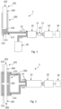
- FIG. 1 shows a first embodiment of the training apparatus (1), which also comprises a reservoir (40) and a hydraulic actuator (100) consisting of a single acting hydraulic cylinder, of which a sectional view is represented.
- This hydraulic actuator (100) includes a movable element (101) and a housing (110) provided with an inner cavity (111).
- the movable element (101) comprises one outer part (102) arranged outside the inner cavity (111) and one inner part (103) arranged inside the inner cavity (111).
- the inner part (103) acts as a plunger configured to hermetically divide the inner cavity (111) into two variable chambers, the volume of which is defined by the relative position of the inner part (103) position within the inner cavity (111).
- the outer part (102) is mechanically joined to the inner part (103) through a longitudinal rod (104), so movement and/or force received at the inner part (103) is transmitted to the outer part (102) and vice versa.
- one chamber of the hydraulic actuator (100) comprises a cavity port (112) in fluid communication with one of said device ports (12) of the hydraulic device (10), while the other one of said device ports (12) is in fluid communication with said reservoir (40). All together they form a hydraulic circuit wherein, when filled with fluid (represented by hatched area), the movable element (101) is configured to push the fluid and the hydraulic device (10) is configured to direct the fluid flow that comes from the hydraulic actuator (100) to the reservoir (40) through its device ports (12), and vice versa, while applying a determined fluid pressure if requested by the control unit (30) through the electric motor (20).
- the hydraulic device (10) is configured so that the rotation speed and torque of its device shaft (11) is inextricably linked to the flow rate and pressure exerted by said fluid through the device ports (12) and vice versa.
- the device shaft (11) is mechanically coupled to the rotary part (21) of the electric motor (20)
- the force exerted at or by the movable element (101) is controlled by the control unit (30) in a dynamic reaction manner.
- FIG 2 shows a second embodiment of the training apparatus (2) comprising a hydraulic actuator (200) consisting of a double acting double rod hydraulic cylinder, of which a sectional view is represented.
- the movable element (201) of this second embodiment comprises two outer parts (202, 206) mechanically joined to one inner part (203) through each longitudinal rod (204, 205).
- the inner part (203) is configured to hermetically divide the inner cavity of the hydraulic actuator (200) into two variable chambers (210, 211) of a same maximum volume.
- Each chamber (210, 211) comprises a corresponding cavity port (212, 213) in fluid communication with a corresponding device port (12) of the hydraulic device (10).
- the movable element (201) is configured to push the fluid from any of the chambers (210, 211) and the hydraulic device (10) is configured to direct the fluid flow that comes from one chamber (210, 211) to the other one through its device ports (12), and vice versa. Therefore, as in the first embodiment, the force exerted at or by the movable element (201) of the present embodiment is controlled by the control unit (30) in a dynamic reaction manner.
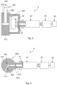
- the hydraulic actuator (300) may also consist of a double acting hydraulic cylinder while its movable element (301) comprises only one outer part (302) and only one rod (304).
- the maximum volume of the chamber (310) comprising the rod (304) is lower than the maximum volume of the other chamber (311), so the training apparatus (3) needs a reservoir (40) and corresponding valves (41) in order to manage the fluid flow from one chamber (310) to the other chamber (311) and vice versa.
- Figure 4 shows a fourth embodiment of the training apparatus (4) comprising a hydraulic actuator (400) consisting of a rotary vane actuator, of which a sectional view is represented.
- the inner cavity of this hydraulic actuator (400) is defined by a circular sector, while the inner part (403) of its movable element (401) is defined by a rotating lever configured to rotate through an axis located at the circular sector centre.
- its outer part (402), not shown in the figure, is also configured to rotate through said axis.
- the inner part (403) is configured to hermetically divide the inner cavity of the hydraulic actuator (400) into two variable chambers (410, 411) of a same maximum volume.
- Each chamber (410, 411) comprises a corresponding cavity port (412, 413) in fluid communication with a corresponding device port (12) of the hydraulic device (10). All together they form a hydraulic circuit filled with fluid, wherein the movable element (401) is configured to push the fluid from any of the chambers (410, 411) and the hydraulic device (10) is configured to direct the fluid flow that comes from one chamber (410, 411) to the other one through its device ports (12), and vice versa. Therefore, as in the previous embodiments, the force exerted at or by the movable element (401) of the present embodiment is controlled by the control unit (30) in a dynamic reaction manner.
- FIG. 5 A similar fifth embodiment of the training apparatus (5) is shown in figure 5 , wherein the hydraulic actuator (500) consist of a rotary vane actuator comprising two inner cavities divided by two inner parts (503, 503') into four chambers (510, 510'. 511, 511'). Each chamber (510, 510'. 511, 511') comprises a corresponding cavity port (512, 512', 513, 513') in fluid communication in pairs with a corresponding device port (12) of the hydraulic device (10).
- the hydraulic actuator (500) consist of a rotary vane actuator comprising two inner cavities divided by two inner parts (503, 503') into four chambers (510, 510'. 511, 511').
- Each chamber (510, 510'. 511, 511') comprises a corresponding cavity port (512, 512', 513, 513') in fluid communication in pairs with a corresponding device port (12) of the hydraulic device (10).
- FIG. 6 shows a sixth embodiment of the training apparatus (6) comprising a hydraulic actuator (600) consisting of a hydraulic motor comprising several variables chambers (610) defined between several rotating levers which act as inner parts (603).
- a hydraulic actuator (600) consisting of a hydraulic motor comprising several variables chambers (610) defined between several rotating levers which act as inner parts (603).
- Two cavity ports (612) of this hydraulic actuator (600) are in fluid communication with each of the two device ports (12) of the hydraulic device (10). The pressure and fluid flow coming from the hydraulic device (10) is converted into torque and rotation of the rotating levers (603) and vice versa.
Landscapes
- Health & Medical Sciences (AREA)
- Physical Education & Sports Medicine (AREA)
- General Health & Medical Sciences (AREA)
- Biophysics (AREA)
- Life Sciences & Earth Sciences (AREA)
- Engineering & Computer Science (AREA)
- Orthopedic Medicine & Surgery (AREA)
- Human Computer Interaction (AREA)
- Multimedia (AREA)
- Physics & Mathematics (AREA)
- Electromagnetism (AREA)
- Rehabilitation Tools (AREA)
- Actuator (AREA)
Claims (14)
- Trainingsvorrichtung (1), umfassend:- mindestens einen Hydraulikaktor (100) einschließlich eines bewegbaren Elements (101) und eines Gehäuses (110), das mit mindestens einem Innenhohlraum (111) versehen ist, der konfiguriert ist, mit einem Fluid gefüllt zu sein, wobei das bewegbare Element (101) mindestens einen Außenabschnitt (102) und mindestens einen Innenabschnitt (103), der mit dem mindestens einen Außenabschnitt (102) mechanisch verbunden ist, aufweist, der mindestens eine Außenabschnitt (102) außerhalb des Gehäuses (110) angeordnet ist und konfiguriert ist, durch einen Anwender in einer ersten Richtung und/oder einer zweiten Richtung, die der ersten Richtung entgegengesetzt ist, bewegt zu werden, wobei der mindestens eine Innenabschnitt (103) innerhalb des mindestens einen Innenhohlraums (111) des Gehäuses (110) bewegbar angeordnet ist und konfiguriert ist, durch das Fluid gedrückt zu werden, wenn er in der ersten Richtung bewegt wird, und/oder das Fluid aus dem mindestens einen Innenhohlraum (111) zu drücken, wenn er in der zweiten Richtung bewegt wird, wobei mindestens einer der Innenhohlräume eine Hohlraumöffnung (112) umfasst, die für einen Fluiddurchfluss geeignet ist,- eine Hydraulikeinrichtung (10) einschließlich zweier Einrichtungsöffnungen (12), die für Fluiddurchfluss geeignet sind, und einer Einrichtungswelle (11), die konfiguriert ist, sich um ihre Längsachse bidirektional zu drehen, wobei die Hydraulikeinrichtung (10) konfiguriert ist, Hydraulikdruck und/oder Durchfluss, die bei beliebigen der Einrichtungsöffnungen (12) empfangen werden, in Drehmoment und/oder Drehung der Einrichtungswelle (11) umzuwandeln und umgekehrt, und mindestens eine der zwei Einrichtungsöffnungen (12) mit der mindestens einen Hohlraumöffnung (112) des mindestens einen Hydraulikaktors (100) in Fluidkommunikation ist, und- einen bidirektionalen Elektromotor (20) und eine Steuereinheit (30), wobei der Elektromotor (20) einen Drehabschnitt (21) aufweist, der an die Einrichtungswelle (11) in einer Weise mechanisch gekoppelt ist, dass ihre Längsdrehung von einem zu dem anderen übertragen wird, und wobei die Steuereinheit (30) mit dem Elektromotor (20) elektronisch verbunden ist und konfiguriert ist, die Drehdynamik des Drehabschnitts (21) zu steuern,dadurch gekennzeichnet, dass der mindestens eine Hydraulikaktor (400) ein Drehschaufelaktor ist, der mindestens eine Innenhohlraum (411) des Drehschaufelaktors durch einen kreisförmigen Sektor definiert ist und der mindestens eine Innenabschnitt (403) durch einen Drehhebel definiert ist, der konfiguriert ist, sich um eine Achse zu drehen, die bei dem Zentrum des kreisförmigen Sektors angeordnet ist.
- Trainingsvorrichtung (1) nach Anspruch 1, wobei der mindestens eine Innenabschnitt (103) den mindestens einen Innenhohlraum (111) in mindestens zwei Kammern hermetisch unterteilt, wobei das Volumen der Kammern veränderlich ist und durch die Relativposition der Position des mindestens einen Innenabschnitts (103) in dem mindestens einen Innenhohlraum (111) definiert ist.
- Trainingsvorrichtung (1) nach Anspruch 2, die einen Behälter (40) umfasst, wobei der mindestens eine Hydraulikaktor (100) ein einfachwirkender Hydraulikzylinder ist, die Hohlraumöffnung (112) seines Innenhohlraums (111) mit einer der zwei Einrichtungsöffnungen (12) der Hydraulikeinrichtung (10) in Fluidkommunikation ist und die weitere der zwei Einrichtungsöffnungen (12) der Hydraulikeinrichtung (10) mit dem Behälter (40) in Fluidkommunikation ist.
- Trainingsvorrichtung (2) nach Anspruch 2, wobei mindestens zwei Kammern (210, 211) des mindestens einen Hydraulikaktors (200) eine entsprechende Hohlraumöffnung (212, 213) umfassen, die für Fluiddurchfluss geeignet ist, und jede der zwei Einrichtungsöffnungen (12) der Hydraulikeinrichtung (10) mit jeder Hohlraumöffnung (212, 213) in Fluidkommunikation ist.
- Trainingsvorrichtung (2) nach Anspruch 4, wobei der mindestens eine Hydraulikaktor (200) ein längs gerichteter doppeltwirkender Hydraulikzylinder ist.
- Trainingsvorrichtung (6) nach Anspruch 1, wobei der mindestens eine Hydraulikaktor (600) ein bidirektionaler Hydraulikmotor ist.
- Trainingsvorrichtung (1) nach einem der vorhergehenden Ansprüche, wobei die Steuereinheit (30) eine Schnittstelleneinheit umfasst, die konfiguriert ist, von einem Anwender die auf den Drehabschnitt (21) auszuübende Drehdynamik zu empfangen.
- Trainingsvorrichtung (1) nach Anspruch 7, wobei die Steuereinheit (30) konfigurierbar ist, den Elektromotor (20) anzuweisen, auf den Drehabschnitt (21) ein bestimmtes Drehmoment in mindestens einer Drehrichtung auszuüben.
- Trainingsvorrichtung (1) nach Anspruch 8, wobei die Steuereinheit (30) konfigurierbar ist, den Elektromotor (20) anzuweisen, Bewegung des Drehabschnitts (21) zu hemmen, bis ein Schwellenanwenderkraftwert auf das bewegbare Element (101) ausgeübt wird.
- Trainingsvorrichtung (1) nach Anspruch 8 oder 9, wobei die Steuereinheit (30) konfigurierbar ist, den Elektromotor (20) anzuweisen, bei verschiedenen Drehstellungen des Drehabschnitts (21) verschiedenes Drehmoment auszuüben.
- Trainingsvorrichtung (1) nach einem der Ansprüche 7 bis 10, wobei die Steuereinheit (30) konfigurierbar ist, den Elektromotor (20) anzuweisen, sich mit einer bestimmten Drehzahl zu drehen.
- Trainingsvorrichtung (1) nach Anspruch 11, wobei die Steuereinheit (30) konfigurierbar ist, den Elektromotor (20) anzuweisen, bei verschiedenen Drehstellungen des Drehabschnitts (21) verschiedene Drehahlen auszuüben.
- Trainingsvorrichtung (1) nach einem der vorhergehenden Ansprüche, wobei die Hydraulikeinrichtung (10) aus einem Hydraulikmotor besteht.
- Trainingsvorrichtung (1) nach einem der Ansprüche 1 bis 13, wobei die Hydraulikeinrichtung (10) aus einer Hydraulikpumpe besteht.
Priority Applications (4)
| Application Number | Priority Date | Filing Date | Title |
|---|---|---|---|
| ES23382071T ES3040197T3 (en) | 2023-01-27 | 2023-01-27 | Training apparatus |
| EP23382071.1A EP4406623B1 (de) | 2023-01-27 | 2023-01-27 | Trainingsgerät |
| PCT/EP2024/051872 WO2024156852A1 (en) | 2023-01-27 | 2024-01-26 | Training apparatus |
| CN202480009382.6A CN120603629A (zh) | 2023-01-27 | 2024-01-26 | 训练设备 |
Applications Claiming Priority (1)
| Application Number | Priority Date | Filing Date | Title |
|---|---|---|---|
| EP23382071.1A EP4406623B1 (de) | 2023-01-27 | 2023-01-27 | Trainingsgerät |
Publications (3)
| Publication Number | Publication Date |
|---|---|
| EP4406623A1 EP4406623A1 (de) | 2024-07-31 |
| EP4406623C0 EP4406623C0 (de) | 2025-06-04 |
| EP4406623B1 true EP4406623B1 (de) | 2025-06-04 |
Family
ID=85150253
Family Applications (1)
| Application Number | Title | Priority Date | Filing Date |
|---|---|---|---|
| EP23382071.1A Active EP4406623B1 (de) | 2023-01-27 | 2023-01-27 | Trainingsgerät |
Country Status (4)
| Country | Link |
|---|---|
| EP (1) | EP4406623B1 (de) |
| CN (1) | CN120603629A (de) |
| ES (1) | ES3040197T3 (de) |
| WO (1) | WO2024156852A1 (de) |
Citations (1)
| Publication number | Priority date | Publication date | Assignee | Title |
|---|---|---|---|---|
| US5064193A (en) * | 1989-11-13 | 1991-11-12 | Walker Fitness Systems, Inc. | Automatic force generating and control system |
Family Cites Families (4)
| Publication number | Priority date | Publication date | Assignee | Title |
|---|---|---|---|---|
| DE3704841C2 (de) * | 1987-02-16 | 1996-06-13 | Kern Guenter | Trainingsgerät |
| US9702349B2 (en) * | 2013-03-15 | 2017-07-11 | ClearMotion, Inc. | Active vehicle suspension system |
| US20180214730A1 (en) * | 2015-08-24 | 2018-08-02 | Exonetik Inc. | Strength training device using magnetorheological fluid clutch apparatus |
| US11058908B2 (en) | 2020-07-22 | 2021-07-13 | David McCann | Weight training apparatus |
-
2023
- 2023-01-27 EP EP23382071.1A patent/EP4406623B1/de active Active
- 2023-01-27 ES ES23382071T patent/ES3040197T3/es active Active
-
2024
- 2024-01-26 CN CN202480009382.6A patent/CN120603629A/zh active Pending
- 2024-01-26 WO PCT/EP2024/051872 patent/WO2024156852A1/en not_active Ceased
Patent Citations (1)
| Publication number | Priority date | Publication date | Assignee | Title |
|---|---|---|---|---|
| US5064193A (en) * | 1989-11-13 | 1991-11-12 | Walker Fitness Systems, Inc. | Automatic force generating and control system |
Also Published As
| Publication number | Publication date |
|---|---|
| EP4406623C0 (de) | 2025-06-04 |
| EP4406623A1 (de) | 2024-07-31 |
| WO2024156852A1 (en) | 2024-08-02 |
| ES3040197T3 (en) | 2025-10-29 |
| CN120603629A (zh) | 2025-09-05 |
Similar Documents
| Publication | Publication Date | Title |
|---|---|---|
| EP3273069B1 (de) | Intelligentes lastabhängiges elektrohydrostatisches stellglied | |
| US9004219B2 (en) | Drive control system | |
| KR100350194B1 (ko) | 가변 용적 축방향 피스톤 유압 장치 | |
| CA2554400A1 (en) | Variable displacement reciprocating pump | |
| US8074451B2 (en) | Electric motor actuation of a hydrostatic pump | |
| CN119137371A (zh) | 液压轴向活塞单元和用于控制液压轴向活塞单元的方法 | |
| CN113915091A (zh) | 一种柱塞泵变量机构、柱塞泵、柱塞泵泵控系统及泵控方法 | |
| JP6998145B2 (ja) | 液圧駆動装置 | |
| EP4406623B1 (de) | Trainingsgerät | |
| JP2002502937A (ja) | ハイドロモータにより援助される活動を遂行するための装置及びこのような装置に使用されるハイドロリックトランスフォーマ | |
| EP2959165B1 (de) | Hydraulisches taumelblockpositionierungssystem | |
| US10316867B2 (en) | Hydraulic rotary actuator with built-in mechanical position feedback | |
| EP2009283B1 (de) | Verbesserung für eine hydraulisch angetriebene Maschine | |
| CN111794928A (zh) | 轴向柱塞机械 | |
| JPS61274161A (ja) | 無段変速機の制御装置 | |
| JP7760371B2 (ja) | 過圧補正を有する液圧アクチュエータ | |
| KR100773987B1 (ko) | 2 펌프 구조의 사판식 액셜 피스톤 유압 펌프 | |
| KR101703375B1 (ko) | 유압모터용 제어장치 및 유압모터 조립체 | |
| US12352253B2 (en) | Servo system bolted on design | |
| KR100319371B1 (ko) | 사판식 가변용량형 병렬펌프 | |
| RU2026206C1 (ru) | Гидромеханическая передача | |
| JPS5840056B2 (ja) | 制御器 | |
| JPH01273882A (ja) | 可変容量形液圧ポンプ装置 |
Legal Events
| Date | Code | Title | Description |
|---|---|---|---|
| PUAI | Public reference made under article 153(3) epc to a published international application that has entered the european phase |
Free format text: ORIGINAL CODE: 0009012 |
|
| STAA | Information on the status of an ep patent application or granted ep patent |
Free format text: STATUS: THE APPLICATION HAS BEEN PUBLISHED |
|
| AK | Designated contracting states |
Kind code of ref document: A1 Designated state(s): AL AT BE BG CH CY CZ DE DK EE ES FI FR GB GR HR HU IE IS IT LI LT LU LV MC ME MK MT NL NO PL PT RO RS SE SI SK SM TR |
|
| RIN1 | Information on inventor provided before grant (corrected) |
Inventor name: MEHTAELAE, ANDREAS EFRAIN ILMARI |
|
| STAA | Information on the status of an ep patent application or granted ep patent |
Free format text: STATUS: REQUEST FOR EXAMINATION WAS MADE |
|
| 17P | Request for examination filed |
Effective date: 20250130 |
|
| GRAP | Despatch of communication of intention to grant a patent |
Free format text: ORIGINAL CODE: EPIDOSNIGR1 |
|
| STAA | Information on the status of an ep patent application or granted ep patent |
Free format text: STATUS: GRANT OF PATENT IS INTENDED |
|
| INTG | Intention to grant announced |
Effective date: 20250319 |
|
| GRAS | Grant fee paid |
Free format text: ORIGINAL CODE: EPIDOSNIGR3 |
|
| GRAA | (expected) grant |
Free format text: ORIGINAL CODE: 0009210 |
|
| STAA | Information on the status of an ep patent application or granted ep patent |
Free format text: STATUS: THE PATENT HAS BEEN GRANTED |
|
| AK | Designated contracting states |
Kind code of ref document: B1 Designated state(s): AL AT BE BG CH CY CZ DE DK EE ES FI FR GB GR HR HU IE IS IT LI LT LU LV MC ME MK MT NL NO PL PT RO RS SE SI SK SM TR |
|
| REG | Reference to a national code |
Ref country code: GB Ref legal event code: FG4D |
|
| REG | Reference to a national code |
Ref country code: CH Ref legal event code: EP |
|
| REG | Reference to a national code |
Ref country code: DE Ref legal event code: R096 Ref document number: 602023003859 Country of ref document: DE |
|
| REG | Reference to a national code |
Ref country code: IE Ref legal event code: FG4D |
|
| U01 | Request for unitary effect filed |
Effective date: 20250630 |
|
| U07 | Unitary effect registered |
Designated state(s): AT BE BG DE DK EE FI FR IT LT LU LV MT NL PT RO SE SI Effective date: 20250704 |
|
| PG25 | Lapsed in a contracting state [announced via postgrant information from national office to epo] |
Ref country code: NO Free format text: LAPSE BECAUSE OF FAILURE TO SUBMIT A TRANSLATION OF THE DESCRIPTION OR TO PAY THE FEE WITHIN THE PRESCRIBED TIME-LIMIT Effective date: 20250904 Ref country code: GR Free format text: LAPSE BECAUSE OF FAILURE TO SUBMIT A TRANSLATION OF THE DESCRIPTION OR TO PAY THE FEE WITHIN THE PRESCRIBED TIME-LIMIT Effective date: 20250905 |
|
| PG25 | Lapsed in a contracting state [announced via postgrant information from national office to epo] |
Ref country code: PL Free format text: LAPSE BECAUSE OF FAILURE TO SUBMIT A TRANSLATION OF THE DESCRIPTION OR TO PAY THE FEE WITHIN THE PRESCRIBED TIME-LIMIT Effective date: 20250604 |
|
| PG25 | Lapsed in a contracting state [announced via postgrant information from national office to epo] |
Ref country code: HR Free format text: LAPSE BECAUSE OF FAILURE TO SUBMIT A TRANSLATION OF THE DESCRIPTION OR TO PAY THE FEE WITHIN THE PRESCRIBED TIME-LIMIT Effective date: 20250604 |
|
| PG25 | Lapsed in a contracting state [announced via postgrant information from national office to epo] |
Ref country code: RS Free format text: LAPSE BECAUSE OF FAILURE TO SUBMIT A TRANSLATION OF THE DESCRIPTION OR TO PAY THE FEE WITHIN THE PRESCRIBED TIME-LIMIT Effective date: 20250904 |
|
| REG | Reference to a national code |
Ref country code: ES Ref legal event code: FG2A Ref document number: 3040197 Country of ref document: ES Kind code of ref document: T3 Effective date: 20251029 |
|
| U20 | Renewal fee for the european patent with unitary effect paid |
Year of fee payment: 4 Effective date: 20251103 |