EP2045168B1 - Hydraulisches Lenksystem für ein Fahrzeug - Google Patents
Hydraulisches Lenksystem für ein Fahrzeug Download PDFInfo
- Publication number
- EP2045168B1 EP2045168B1 EP07425624A EP07425624A EP2045168B1 EP 2045168 B1 EP2045168 B1 EP 2045168B1 EP 07425624 A EP07425624 A EP 07425624A EP 07425624 A EP07425624 A EP 07425624A EP 2045168 B1 EP2045168 B1 EP 2045168B1
- Authority
- EP
- European Patent Office
- Prior art keywords
- steering
- hydraulic
- vehicle
- shaft
- pump
- Prior art date
- Legal status (The legal status is an assumption and is not a legal conclusion. Google has not performed a legal analysis and makes no representation as to the accuracy of the status listed.)
- Active
Links
Images
Classifications
-
- B—PERFORMING OPERATIONS; TRANSPORTING
- B62—LAND VEHICLES FOR TRAVELLING OTHERWISE THAN ON RAILS
- B62D—MOTOR VEHICLES; TRAILERS
- B62D5/00—Power-assisted or power-driven steering
- B62D5/06—Power-assisted or power-driven steering fluid, i.e. using a pressurised fluid for most or all the force required for steering a vehicle
- B62D5/09—Power-assisted or power-driven steering fluid, i.e. using a pressurised fluid for most or all the force required for steering a vehicle characterised by means for actuating valves
- B62D5/093—Telemotor driven by steering wheel movement
-
- B—PERFORMING OPERATIONS; TRANSPORTING
- B62—LAND VEHICLES FOR TRAVELLING OTHERWISE THAN ON RAILS
- B62D—MOTOR VEHICLES; TRAILERS
- B62D1/00—Steering controls, i.e. means for initiating a change of direction of the vehicle
- B62D1/02—Steering controls, i.e. means for initiating a change of direction of the vehicle vehicle-mounted
- B62D1/16—Steering columns
-
- B—PERFORMING OPERATIONS; TRANSPORTING
- B62—LAND VEHICLES FOR TRAVELLING OTHERWISE THAN ON RAILS
- B62D—MOTOR VEHICLES; TRAILERS
- B62D3/00—Steering gears
- B62D3/14—Steering gears hydraulic
Definitions
- the present invention relates to a steering system for an agricultural or construction vehicle of the type comprising a hydraulic steering motor.
- hydraulic steering motor is used herein in its normally accepted sense to refer to a device that incorporates an internal pump, a distribution valve, an input shaft which in use is coupled for rotation by the steering shaft of a vehicle steering wheel, and connectors for hydraulic lines leading to a high pressure source of oil, to an oil reservoir and to hydraulic actuators connected to the steerable wheels of the vehicle.
- Hydraulic steering systems of this kind are commonly used in agricultural vehicles, such as tractors and harvesters, that require power-assisted steering.
- the steering motor comprises a pump that is rotated by the torque applied to the steering wheel and a distribution valve.
- the distribution valve acts to direct the high pressure hydraulic fluid, herein termed oil for simplicity, generated by the internal pump to hydraulic steering actuators connected to the steerable wheels and to direct oil returning from the actuators to reservoir.
- the construction of the steering actuators is not material to the present invention and they may comprise two separate hydraulic jacks or a cylinder with a double acting piston.
- an auxiliary pump is connected to the steering motor to supply it with oil under high pressure.
- the distribution valve serves to apply the high pressure oil to the steering actuators in a manner to supplement the oil pressure generated by the internal pump, thereby providing power assistance.
- the torque applied by the driver to drive the internal pump of the steering motor is of itself sufficient to steer the vehicle.
- high pressure oil is available from the auxiliary pump, however, it is applied through the distribution valve to the wheel actuators in parallel with the oil from the internal pump so that the wheels are turned by the same desired amount but without as much driver effort.
- the construction of the steering motor need not be considered in the present context in more detail as it is well known in the art and commercially available, for example, from Danfoss.
- the input shaft of the steering pump is directly coupled to the lower end of the steering shaft on which the vehicle steering wheel is mounted and the body of the steering pump is located within the driver's cabin.
- DE 1 480 205 A discloses a steering assembly where the steering pump is connected to the steering wheel by a shaft. Said pump further remotely activates the steering wheels with the help of an electrical pump and valve.
- US 2007/0017730 A representing the closest prior art discloses a further steering system comprising at least two steering cylinders and an adjustable hydraulic pump.
- the steering wheel adjusts the swash plate of the hydraulic pump through an adjusting valve to remotely activate the steering cylinders.
- a problem of such conventional mounting of the steering pump is that space within the cabin is often at a premium and the steering pump can prove an unpleasant source of noise.
- the present invention provides a steering system of an agricultural vehicle of the type according to claim 1.
- the rotary actuators mounted on the steering shaft and the steering motor are cycloidal or gerotor pumps and motors.
- a gerotor is a known hydraulic machine that can function as a pump or as a motor and is of the N,N-1 type of machine.
- Such machines of which the well-known Wankel engine is an example, comprise a rotor with N outwardly facing lobes rotating eccentrically inside a body with N-1 inwardly facing lobes.
- the lobes are shaped as epitrochoids and hypotrochoids so that they remain in contact with one another at all times to define N working chambers, each of which expands then contracts as the rotor rotates.
- the body with N-1 inwardly facing lobes is itself a second rotor rotating in the same direction as the rotor with N outwardly facing lobes.
- This rotation of the second rotor enables the working chambers to communicate with stationary high pressure and low pressure ports.
- gerotors are themselves known and well described in the prior art, they need not be described in greater detail in the present context.
- the gerotor driven by the steering shaft acts as a pump and that connected to the steering motor as a motor turning the input shaft of the steering motor in proportion to the rotation of the steering wheel. If the two gerotors are identical then, disregarding any internal oil leakage, the steering shaft and the input shaft of the steering motor will rotate by equal amounts but it is possible to provide torque multiplication by using differently dimensioned gerotors.
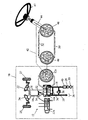
- the single figure shows a steering system in which all the components lying within the box 10 drawn in dotted lines represent a conventional hydraulic power-assisted steering system and these will be briefly described first.
- the steering motor 12 is represented in the drawing by three separate parts, namely a housing 12a, a distribution valve spool 12b and an internal pump 12c, itself constructed in the illustrated embodiment as a gerotor pump.
- the housing 12a has connectors for four hydraulic lines 14, 16, 18 and 20.
- An input shaft (not shown) of the steering motor serves to drive the gerotor pump 12 and to rotate the valve spool 12b relative to the housing 12a.
- the lines 14 and 16 lead to hydraulic actuators 22 and 24 shown as double acting hydraulic jacks with differential pistons that act on the steerable wheels 25 and 27 of the vehicle.
- the line 18 is a high pressure supply line and the line 20 a return line. Oil in the high pressure line 18 is drawn from a reservoir 26 by an auxiliary pump 28 by way of a filter 30.
- the power-assisted steering system also includes various non-return valve 32, 34 and 36 and a high pressure regulating or relief valve 38 as well as a device 40 used for cavity control.
- the input shaft of the steering motor 12 is directly coupled to the steering shaft 44 of the steering wheel 47 of the vehicle.
- the ability of the cab of an agricultural vehicle to move relative to the chassis creates complications as shock absorbing mountings need to be used for mounting the steering motor 12 in the cab and flexible hoses must be used for the hydraulic lines 16 to 20.
- the present invention proposes separating the steering motor 12 from the steering shaft 44.
- This permits the steering motor to be mounted on the chassis of the vehicle and allows the hydraulic lines to be constructed as rigid pipes.
- a rotary hydraulic coupling is provided which comprises first and second gerotors 46 and 48 connected by lines 50 and 52 in a closed circuit.
- the first gerotor 46 is directly coupled to the steering shaft 44 within the cab and acts as a hydraulic pump.
- the second gerotor 48 is mounted remotely on the input shaft of the steering motor 12 and acts as a motor driven by the hydraulic pressure created in lines 50 and 52 by the first gerotor pump 46.
- the gerotor 46 connected to the steering shaft in the present invention may be rigidly mounted on the body of the cab, which in turn simplifies the connection between the gerotor 46 and the steering shaft 44.
- a further advantage offered by the invention is that the relocation of the steering motor 12 outside the cab allows it, if desired, to be integrated into other components of the steering system, such as the auxiliary pump 28 or the actuators 22, 24.
- the resulting reduction in the length of the lines 14 to 20 makes for a neater installation, with less risk of damage to the hydraulic lines.
- Noise in the cab is reduced because of the remote location of the steering pump and the use of hydraulic lines 50 and 52, as opposed to cables, ensure that little of the noise is transmitted back into the cab.
- a still further advantage of the invention is that the transmission ratio between the steering shaft and the steering motor may be varied by simply replacing one of the first and second gerotors 46 and 48 with one having a different displacement.
Landscapes
- Engineering & Computer Science (AREA)
- Chemical & Material Sciences (AREA)
- Combustion & Propulsion (AREA)
- Transportation (AREA)
- Mechanical Engineering (AREA)
- Power Steering Mechanism (AREA)
- Guiding Agricultural Machines (AREA)
Claims (4)
- Lenksystem eines Fahrzeuges von dem Typ, der einen hydraulischen Lenkmotor (12) umfasst, der eine interne Gerotor-Pumpe (12c), ein Verteilerventil (12b), eine Eingangswelle und Verbindungseinrichtungen für Hydraulikleitungen (14, 16, 18, 20) beinhaltet, wobei der Lenkmotor (12) an einer von der Lenkwelle (44) entfernten Stelle angeordnet und für eine Drehung mit dieser durch eine erste Gerotor-Pumpe (46), die im Betrieb direkt mit der Lenkwelle (44) gekoppelt ist, und durch eine zweite Gerotor-Pumpe (48) gekoppelt ist, die an der entfernten Stelle auf der Eingangswelle des Lenkmotors (12) befestigt ist, wobei die Gerotor-Pumpen (46, 48) in einem geschlossenen Kreislauf miteinander angeordnet sind.
- Lenksystem nach Anspruch 1, bei dem die ersten und zweiten Gerotor-Pumpen (46, 48), die auf der Lenkwelle (44) beziehungsweise dem Lenkmotor (12) befestigt sind, eine voneinander abweichende Verdrängung aufweisen.
- Lenksystem nach einem der vorhergehenden Ansprüche, bei dem zumindest eine der hydraulischen Gerotor-Pumpen (46, 48) und die die Pumpen in einem geschlossenen Kreislauf miteinander verbindenden Hydraulikleitungen aus einem synthetischen oder Kunststoffmaterial hergestellt sind.
- Lenksystem nach einem der vorhergehenden Ansprüche, bei dem die erste Gerotor-Pumpe (46) auf der Lenkwelle (44) starr in der Kabine des Fahrzeugs befestigt ist.
Priority Applications (4)
| Application Number | Priority Date | Filing Date | Title |
|---|---|---|---|
| AT07425624T ATE492455T1 (de) | 2007-10-05 | 2007-10-05 | Hydraulisches lenksystem für ein fahrzeug |
| EP07425624A EP2045168B1 (de) | 2007-10-05 | 2007-10-05 | Hydraulisches Lenksystem für ein Fahrzeug |
| DE602007011451T DE602007011451D1 (de) | 2007-10-05 | 2007-10-05 | Hydraulisches Lenksystem für ein Fahrzeug |
| US12/245,338 US7798280B2 (en) | 2007-10-05 | 2008-10-03 | Hydraulic steering system for a vehicle |
Applications Claiming Priority (1)
| Application Number | Priority Date | Filing Date | Title |
|---|---|---|---|
| EP07425624A EP2045168B1 (de) | 2007-10-05 | 2007-10-05 | Hydraulisches Lenksystem für ein Fahrzeug |
Publications (2)
| Publication Number | Publication Date |
|---|---|
| EP2045168A1 EP2045168A1 (de) | 2009-04-08 |
| EP2045168B1 true EP2045168B1 (de) | 2010-12-22 |
Family
ID=39133788
Family Applications (1)
| Application Number | Title | Priority Date | Filing Date |
|---|---|---|---|
| EP07425624A Active EP2045168B1 (de) | 2007-10-05 | 2007-10-05 | Hydraulisches Lenksystem für ein Fahrzeug |
Country Status (4)
| Country | Link |
|---|---|
| US (1) | US7798280B2 (de) |
| EP (1) | EP2045168B1 (de) |
| AT (1) | ATE492455T1 (de) |
| DE (1) | DE602007011451D1 (de) |
Families Citing this family (7)
| Publication number | Priority date | Publication date | Assignee | Title |
|---|---|---|---|---|
| IT1392732B1 (it) * | 2009-01-27 | 2012-03-16 | Palmarix Ltd | Sistema per il controllo della guida di un veicolo. |
| US9101090B2 (en) * | 2013-05-30 | 2015-08-11 | Cnh Industrial America Llc | Windrower autoguidance hydraulic steering interface |
| US9222598B1 (en) * | 2013-10-02 | 2015-12-29 | Peter Smith | Adjustable valve wrench |
| CN104149849B (zh) * | 2014-09-01 | 2017-02-15 | 山推工程机械股份有限公司 | 一种液压转向制动系统及液控转向制动阀 |
| DE102016002443A1 (de) | 2016-02-29 | 2017-08-31 | Bomag Gmbh | Lenkeinrichtung, Baumaschine mit einer Lenkeinrichtung und Verfahren zum Lenken einer lenkbaren Maschine |
| DE102017201375A1 (de) | 2017-01-30 | 2018-08-02 | Audi Ag | Kraftfahrzeug |
| CN110745180A (zh) * | 2018-07-23 | 2020-02-04 | 郑州宇通客车股份有限公司 | 一种四轮液压转向助力系统及车辆 |
Family Cites Families (15)
| Publication number | Priority date | Publication date | Assignee | Title |
|---|---|---|---|---|
| USRE25126E (en) * | 1958-11-25 | 1962-02-20 | Controller for fluid pressure operated devices | |
| DE1480205A1 (de) | 1964-07-21 | 1969-04-17 | Hans Still Gmbh | Hilfskraftunterstuetzte Lenkeinrichtung fuer Elektro-Flurfoerdergeraete |
| US3452543A (en) * | 1967-11-06 | 1969-07-01 | Trw Inc | Hydrostatic device |
| US3688860A (en) * | 1971-04-27 | 1972-09-05 | Lloyd A Molby | Two speed steering system |
| USRE31067E (en) * | 1973-10-19 | 1982-10-26 | Trw Inc. | Hydrostatic control unit |
| FR2636289B1 (fr) * | 1988-09-14 | 1990-12-07 | Equip Systemes Mecanismes | Transmission pour vehicules chenilles rapides ou a roues non directrices |
| US4936094A (en) * | 1989-01-17 | 1990-06-26 | Eaton Corporation | Torque-generating steering device with load-sensing capability |
| US4972916A (en) * | 1989-04-25 | 1990-11-27 | Trw Inc. | Vehicle steering system |
| DE19714785B4 (de) * | 1997-04-10 | 2005-07-21 | Sauer-Danfoss Holding Aps | Hydraulische Lenkeinrichtung |
| EP0926045A3 (de) * | 1997-12-15 | 2001-05-02 | KABUSHIKI KAISHA KOBE SEIKO SHO also known as Kobe Steel Ltd. | Lenksystem in einem Fahrzeug |
| US6910699B2 (en) * | 2003-05-30 | 2005-06-28 | Deere & Company | Magnetorheological fluid brake and force-feedback system for a steering mechanism |
| DE10331534B4 (de) | 2003-07-11 | 2008-01-17 | Brueninghaus Hydromatik Gmbh | Hydraulisches Lenksystem für mobile Arbeitsmaschinen |
| WO2005100780A2 (en) * | 2004-04-09 | 2005-10-27 | Hybra-Drive Systems, Llc | Variable capacity pump/motor |
| US7281376B2 (en) * | 2005-02-22 | 2007-10-16 | Hybra-Drive Systems, Llc | Hydraulic hybrid powertrain system |
| DE102006019803B4 (de) * | 2006-04-28 | 2008-11-27 | Sauer-Danfoss Aps | Hydraulische Lenkung |
-
2007
- 2007-10-05 EP EP07425624A patent/EP2045168B1/de active Active
- 2007-10-05 DE DE602007011451T patent/DE602007011451D1/de active Active
- 2007-10-05 AT AT07425624T patent/ATE492455T1/de not_active IP Right Cessation
-
2008
- 2008-10-03 US US12/245,338 patent/US7798280B2/en not_active Expired - Fee Related
Also Published As
| Publication number | Publication date |
|---|---|
| US20090095561A1 (en) | 2009-04-16 |
| US7798280B2 (en) | 2010-09-21 |
| EP2045168A1 (de) | 2009-04-08 |
| ATE492455T1 (de) | 2011-01-15 |
| DE602007011451D1 (de) | 2011-02-03 |
Similar Documents
| Publication | Publication Date | Title |
|---|---|---|
| US7798280B2 (en) | Hydraulic steering system for a vehicle | |
| US6672843B1 (en) | Dual pump apparatus comprising dual drive shafts and auxiliary pump | |
| EP1302355B1 (de) | Getriebe für ein Arbeitsfahrzeug und Fahrzeug | |
| US8517138B2 (en) | Hydraulic motor unit and hydraulic four-wheel-drive working vehicle | |
| EP2011683A2 (de) | Arbeitsfahrzeug mit hydraulischem Radantrieb | |
| US7487856B2 (en) | Electrically actuated, hydraulic power steering system | |
| KR102174602B1 (ko) | 자동차의 조향장치 | |
| US3433127A (en) | Power steering system with hydraulic reaction | |
| WO1996015375A1 (en) | Unitary electro-hydraulic rotary actuator for automotive convertible top | |
| US5303793A (en) | Steering apparatus | |
| EP2093091A2 (de) | Hydraulisches Vierradantriebsarbeitsfahrzeug | |
| US7204170B2 (en) | Device for transmitting torque between two rotatable, coaxial shaft members | |
| US4262580A (en) | Power steering system with auxiliary power capability | |
| US5529136A (en) | Articulated machine with powered differential steering | |
| US20050092948A1 (en) | Power steering valve | |
| US6029560A (en) | Fluid pressure operated torque amplifier and a vehicular power steering system incorporating same | |
| JP3321493B2 (ja) | 作業車の油圧無段変速装置付きトランスミッション | |
| GB2380234A (en) | A limited slip differential with hydraulic pump/motor | |
| EP2591938A1 (de) | Hydraulisches vierradantriebsarbeitsfahrzeug | |
| US6443036B1 (en) | Mechanical-hydrostatic transmission, particularly for tools and vehicles suitable for gardening, such as lawn-mowers or the like | |
| WO2014095631A1 (en) | Hydraulic drive mounting | |
| USRE30291E (en) | Power steering system with auxiliary power capability | |
| US20070060435A1 (en) | Hydraulic transaxle apparatus | |
| EP0116763B1 (de) | Hydrostatische Transaxle-Vorrichtung | |
| KR940002083B1 (ko) | 동력조향장치 |
Legal Events
| Date | Code | Title | Description |
|---|---|---|---|
| PUAI | Public reference made under article 153(3) epc to a published international application that has entered the european phase |
Free format text: ORIGINAL CODE: 0009012 |
|
| AK | Designated contracting states |
Kind code of ref document: A1 Designated state(s): AT BE BG CH CY CZ DE DK EE ES FI FR GB GR HU IE IS IT LI LT LU LV MC MT NL PL PT RO SE SI SK TR |
|
| AX | Request for extension of the european patent |
Extension state: AL BA HR MK RS |
|
| 17P | Request for examination filed |
Effective date: 20091008 |
|
| AKX | Designation fees paid |
Designated state(s): AT BE BG CH CY CZ DE DK EE ES FI FR GB GR HU IE IS IT LI LT LU LV MC MT NL PL PT RO SE SI SK TR |
|
| 17Q | First examination report despatched |
Effective date: 20091120 |
|
| GRAP | Despatch of communication of intention to grant a patent |
Free format text: ORIGINAL CODE: EPIDOSNIGR1 |
|
| GRAS | Grant fee paid |
Free format text: ORIGINAL CODE: EPIDOSNIGR3 |
|
| GRAA | (expected) grant |
Free format text: ORIGINAL CODE: 0009210 |
|
| AK | Designated contracting states |
Kind code of ref document: B1 Designated state(s): AT BE BG CH CY CZ DE DK EE ES FI FR GB GR HU IE IS IT LI LT LU LV MC MT NL PL PT RO SE SI SK TR |
|
| REG | Reference to a national code |
Ref country code: GB Ref legal event code: FG4D |
|
| REG | Reference to a national code |
Ref country code: CH Ref legal event code: EP |
|
| REG | Reference to a national code |
Ref country code: IE Ref legal event code: FG4D |
|
| RAP2 | Party data changed (patent owner data changed or rights of a patent transferred) |
Owner name: CNH ITALIA S.P.A. |
|
| REF | Corresponds to: |
Ref document number: 602007011451 Country of ref document: DE Date of ref document: 20110203 Kind code of ref document: P |
|
| REG | Reference to a national code |
Ref country code: DE Ref legal event code: R096 Ref document number: 602007011451 Country of ref document: DE Effective date: 20110203 |
|
| RAP2 | Party data changed (patent owner data changed or rights of a patent transferred) |
Owner name: CNH ITALIA S.P.A. |
|
| REG | Reference to a national code |
Ref country code: NL Ref legal event code: VDEP Effective date: 20101222 |
|
| PG25 | Lapsed in a contracting state [announced via postgrant information from national office to epo] |
Ref country code: LT Free format text: LAPSE BECAUSE OF FAILURE TO SUBMIT A TRANSLATION OF THE DESCRIPTION OR TO PAY THE FEE WITHIN THE PRESCRIBED TIME-LIMIT Effective date: 20101222 |
|
| LTIE | Lt: invalidation of european patent or patent extension |
Effective date: 20101222 |
|
| PG25 | Lapsed in a contracting state [announced via postgrant information from national office to epo] |
Ref country code: CY Free format text: LAPSE BECAUSE OF FAILURE TO SUBMIT A TRANSLATION OF THE DESCRIPTION OR TO PAY THE FEE WITHIN THE PRESCRIBED TIME-LIMIT Effective date: 20101222 Ref country code: BG Free format text: LAPSE BECAUSE OF FAILURE TO SUBMIT A TRANSLATION OF THE DESCRIPTION OR TO PAY THE FEE WITHIN THE PRESCRIBED TIME-LIMIT Effective date: 20110322 Ref country code: SI Free format text: LAPSE BECAUSE OF FAILURE TO SUBMIT A TRANSLATION OF THE DESCRIPTION OR TO PAY THE FEE WITHIN THE PRESCRIBED TIME-LIMIT Effective date: 20101222 Ref country code: SE Free format text: LAPSE BECAUSE OF FAILURE TO SUBMIT A TRANSLATION OF THE DESCRIPTION OR TO PAY THE FEE WITHIN THE PRESCRIBED TIME-LIMIT Effective date: 20101222 Ref country code: AT Free format text: LAPSE BECAUSE OF FAILURE TO SUBMIT A TRANSLATION OF THE DESCRIPTION OR TO PAY THE FEE WITHIN THE PRESCRIBED TIME-LIMIT Effective date: 20101222 Ref country code: LV Free format text: LAPSE BECAUSE OF FAILURE TO SUBMIT A TRANSLATION OF THE DESCRIPTION OR TO PAY THE FEE WITHIN THE PRESCRIBED TIME-LIMIT Effective date: 20101222 Ref country code: FI Free format text: LAPSE BECAUSE OF FAILURE TO SUBMIT A TRANSLATION OF THE DESCRIPTION OR TO PAY THE FEE WITHIN THE PRESCRIBED TIME-LIMIT Effective date: 20101222 |
|
| PG25 | Lapsed in a contracting state [announced via postgrant information from national office to epo] |
Ref country code: CZ Free format text: LAPSE BECAUSE OF FAILURE TO SUBMIT A TRANSLATION OF THE DESCRIPTION OR TO PAY THE FEE WITHIN THE PRESCRIBED TIME-LIMIT Effective date: 20101222 Ref country code: ES Free format text: LAPSE BECAUSE OF FAILURE TO SUBMIT A TRANSLATION OF THE DESCRIPTION OR TO PAY THE FEE WITHIN THE PRESCRIBED TIME-LIMIT Effective date: 20110402 Ref country code: PT Free format text: LAPSE BECAUSE OF FAILURE TO SUBMIT A TRANSLATION OF THE DESCRIPTION OR TO PAY THE FEE WITHIN THE PRESCRIBED TIME-LIMIT Effective date: 20110422 Ref country code: IS Free format text: LAPSE BECAUSE OF FAILURE TO SUBMIT A TRANSLATION OF THE DESCRIPTION OR TO PAY THE FEE WITHIN THE PRESCRIBED TIME-LIMIT Effective date: 20110422 Ref country code: GR Free format text: LAPSE BECAUSE OF FAILURE TO SUBMIT A TRANSLATION OF THE DESCRIPTION OR TO PAY THE FEE WITHIN THE PRESCRIBED TIME-LIMIT Effective date: 20110323 Ref country code: BE Free format text: LAPSE BECAUSE OF FAILURE TO SUBMIT A TRANSLATION OF THE DESCRIPTION OR TO PAY THE FEE WITHIN THE PRESCRIBED TIME-LIMIT Effective date: 20101222 Ref country code: EE Free format text: LAPSE BECAUSE OF FAILURE TO SUBMIT A TRANSLATION OF THE DESCRIPTION OR TO PAY THE FEE WITHIN THE PRESCRIBED TIME-LIMIT Effective date: 20101222 |
|
| PG25 | Lapsed in a contracting state [announced via postgrant information from national office to epo] |
Ref country code: RO Free format text: LAPSE BECAUSE OF FAILURE TO SUBMIT A TRANSLATION OF THE DESCRIPTION OR TO PAY THE FEE WITHIN THE PRESCRIBED TIME-LIMIT Effective date: 20101222 Ref country code: SK Free format text: LAPSE BECAUSE OF FAILURE TO SUBMIT A TRANSLATION OF THE DESCRIPTION OR TO PAY THE FEE WITHIN THE PRESCRIBED TIME-LIMIT Effective date: 20101222 Ref country code: PL Free format text: LAPSE BECAUSE OF FAILURE TO SUBMIT A TRANSLATION OF THE DESCRIPTION OR TO PAY THE FEE WITHIN THE PRESCRIBED TIME-LIMIT Effective date: 20101222 Ref country code: NL Free format text: LAPSE BECAUSE OF FAILURE TO SUBMIT A TRANSLATION OF THE DESCRIPTION OR TO PAY THE FEE WITHIN THE PRESCRIBED TIME-LIMIT Effective date: 20101222 |
|
| PLBE | No opposition filed within time limit |
Free format text: ORIGINAL CODE: 0009261 |
|
| STAA | Information on the status of an ep patent application or granted ep patent |
Free format text: STATUS: NO OPPOSITION FILED WITHIN TIME LIMIT |
|
| PG25 | Lapsed in a contracting state [announced via postgrant information from national office to epo] |
Ref country code: DK Free format text: LAPSE BECAUSE OF FAILURE TO SUBMIT A TRANSLATION OF THE DESCRIPTION OR TO PAY THE FEE WITHIN THE PRESCRIBED TIME-LIMIT Effective date: 20101222 |
|
| 26N | No opposition filed |
Effective date: 20110923 |
|
| REG | Reference to a national code |
Ref country code: DE Ref legal event code: R097 Ref document number: 602007011451 Country of ref document: DE Effective date: 20110923 |
|
| PG25 | Lapsed in a contracting state [announced via postgrant information from national office to epo] |
Ref country code: MC Free format text: LAPSE BECAUSE OF NON-PAYMENT OF DUE FEES Effective date: 20111031 |
|
| REG | Reference to a national code |
Ref country code: CH Ref legal event code: PL |
|
| PG25 | Lapsed in a contracting state [announced via postgrant information from national office to epo] |
Ref country code: LI Free format text: LAPSE BECAUSE OF NON-PAYMENT OF DUE FEES Effective date: 20111031 Ref country code: CH Free format text: LAPSE BECAUSE OF NON-PAYMENT OF DUE FEES Effective date: 20111031 |
|
| REG | Reference to a national code |
Ref country code: IE Ref legal event code: MM4A |
|
| PG25 | Lapsed in a contracting state [announced via postgrant information from national office to epo] |
Ref country code: IE Free format text: LAPSE BECAUSE OF NON-PAYMENT OF DUE FEES Effective date: 20111005 |
|
| PG25 | Lapsed in a contracting state [announced via postgrant information from national office to epo] |
Ref country code: MT Free format text: LAPSE BECAUSE OF FAILURE TO SUBMIT A TRANSLATION OF THE DESCRIPTION OR TO PAY THE FEE WITHIN THE PRESCRIBED TIME-LIMIT Effective date: 20101222 |
|
| PG25 | Lapsed in a contracting state [announced via postgrant information from national office to epo] |
Ref country code: LU Free format text: LAPSE BECAUSE OF NON-PAYMENT OF DUE FEES Effective date: 20111005 |
|
| PG25 | Lapsed in a contracting state [announced via postgrant information from national office to epo] |
Ref country code: TR Free format text: LAPSE BECAUSE OF FAILURE TO SUBMIT A TRANSLATION OF THE DESCRIPTION OR TO PAY THE FEE WITHIN THE PRESCRIBED TIME-LIMIT Effective date: 20101222 |
|
| PG25 | Lapsed in a contracting state [announced via postgrant information from national office to epo] |
Ref country code: HU Free format text: LAPSE BECAUSE OF FAILURE TO SUBMIT A TRANSLATION OF THE DESCRIPTION OR TO PAY THE FEE WITHIN THE PRESCRIBED TIME-LIMIT Effective date: 20101222 |
|
| REG | Reference to a national code |
Ref country code: DE Ref legal event code: R082 Ref document number: 602007011451 Country of ref document: DE Representative=s name: PATENTANWAELTE WALLACH, KOCH & PARTNER, DE |
|
| REG | Reference to a national code |
Ref country code: DE Ref legal event code: R082 Ref document number: 602007011451 Country of ref document: DE Representative=s name: PATENTANWAELTE WALLACH, KOCH & PARTNER, DE Effective date: 20140623 Ref country code: DE Ref legal event code: R081 Ref document number: 602007011451 Country of ref document: DE Owner name: CNH INDUSTRIAL ITALIA S.P.A., IT Free format text: FORMER OWNER: CNH ITALIA S.P.A., TURIN, IT Effective date: 20140623 Ref country code: DE Ref legal event code: R082 Ref document number: 602007011451 Country of ref document: DE Representative=s name: PATENTANWAELTE WALLACH, KOCH, DR. HAIBACH, FEL, DE Effective date: 20140623 |
|
| REG | Reference to a national code |
Ref country code: FR Ref legal event code: CD Owner name: CNH INDUSTRIAL ITALIA S.P.A. Effective date: 20150313 |
|
| REG | Reference to a national code |
Ref country code: FR Ref legal event code: PLFP Year of fee payment: 9 |
|
| REG | Reference to a national code |
Ref country code: FR Ref legal event code: PLFP Year of fee payment: 10 |
|
| REG | Reference to a national code |
Ref country code: FR Ref legal event code: PLFP Year of fee payment: 11 |
|
| REG | Reference to a national code |
Ref country code: FR Ref legal event code: PLFP Year of fee payment: 12 |
|
| PGFP | Annual fee paid to national office [announced via postgrant information from national office to epo] |
Ref country code: GB Payment date: 20191025 Year of fee payment: 13 |
|
| REG | Reference to a national code |
Ref country code: DE Ref legal event code: R082 Ref document number: 602007011451 Country of ref document: DE Representative=s name: MEISSNER BOLTE PATENTANWAELTE RECHTSANWAELTE P, DE |
|
| REG | Reference to a national code |
Ref country code: DE Ref legal event code: R084 Ref document number: 602007011451 Country of ref document: DE |
|
| GBPC | Gb: european patent ceased through non-payment of renewal fee |
Effective date: 20201005 |
|
| PG25 | Lapsed in a contracting state [announced via postgrant information from national office to epo] |
Ref country code: GB Free format text: LAPSE BECAUSE OF NON-PAYMENT OF DUE FEES Effective date: 20201005 |
|
| PGFP | Annual fee paid to national office [announced via postgrant information from national office to epo] |
Ref country code: DE Payment date: 20251028 Year of fee payment: 19 |
|
| PGFP | Annual fee paid to national office [announced via postgrant information from national office to epo] |
Ref country code: IT Payment date: 20251024 Year of fee payment: 19 |
|
| PGFP | Annual fee paid to national office [announced via postgrant information from national office to epo] |
Ref country code: FR Payment date: 20251027 Year of fee payment: 19 |