EP2391518B1 - Flywheel module - Google Patents
Flywheel module Download PDFInfo
- Publication number
- EP2391518B1 EP2391518B1 EP10707691.1A EP10707691A EP2391518B1 EP 2391518 B1 EP2391518 B1 EP 2391518B1 EP 10707691 A EP10707691 A EP 10707691A EP 2391518 B1 EP2391518 B1 EP 2391518B1
- Authority
- EP
- European Patent Office
- Prior art keywords
- coupling
- flywheel
- output
- flywheel module
- transmission
- Prior art date
- Legal status (The legal status is an assumption and is not a legal conclusion. Google has not performed a legal analysis and makes no representation as to the accuracy of the status listed.)
- Active
Links
Images
Classifications
-
- B—PERFORMING OPERATIONS; TRANSPORTING
- B60—VEHICLES IN GENERAL
- B60K—ARRANGEMENT OR MOUNTING OF PROPULSION UNITS OR OF TRANSMISSIONS IN VEHICLES; ARRANGEMENT OR MOUNTING OF PLURAL DIVERSE PRIME-MOVERS IN VEHICLES; AUXILIARY DRIVES FOR VEHICLES; INSTRUMENTATION OR DASHBOARDS FOR VEHICLES; ARRANGEMENTS IN CONNECTION WITH COOLING, AIR INTAKE, GAS EXHAUST OR FUEL SUPPLY OF PROPULSION UNITS IN VEHICLES
- B60K6/00—Arrangement or mounting of plural diverse prime-movers for mutual or common propulsion, e.g. hybrid propulsion systems comprising electric motors and internal combustion engines
- B60K6/08—Prime-movers comprising combustion engines and mechanical or fluid energy storing means
- B60K6/10—Prime-movers comprising combustion engines and mechanical or fluid energy storing means by means of a chargeable mechanical accumulator, e.g. flywheel
- B60K6/105—Prime-movers comprising combustion engines and mechanical or fluid energy storing means by means of a chargeable mechanical accumulator, e.g. flywheel the accumulator being a flywheel
-
- B—PERFORMING OPERATIONS; TRANSPORTING
- B60—VEHICLES IN GENERAL
- B60K—ARRANGEMENT OR MOUNTING OF PROPULSION UNITS OR OF TRANSMISSIONS IN VEHICLES; ARRANGEMENT OR MOUNTING OF PLURAL DIVERSE PRIME-MOVERS IN VEHICLES; AUXILIARY DRIVES FOR VEHICLES; INSTRUMENTATION OR DASHBOARDS FOR VEHICLES; ARRANGEMENTS IN CONNECTION WITH COOLING, AIR INTAKE, GAS EXHAUST OR FUEL SUPPLY OF PROPULSION UNITS IN VEHICLES
- B60K6/00—Arrangement or mounting of plural diverse prime-movers for mutual or common propulsion, e.g. hybrid propulsion systems comprising electric motors and internal combustion engines
- B60K6/08—Prime-movers comprising combustion engines and mechanical or fluid energy storing means
- B60K6/12—Prime-movers comprising combustion engines and mechanical or fluid energy storing means by means of a chargeable fluidic accumulator
-
- B—PERFORMING OPERATIONS; TRANSPORTING
- B60—VEHICLES IN GENERAL
- B60K—ARRANGEMENT OR MOUNTING OF PROPULSION UNITS OR OF TRANSMISSIONS IN VEHICLES; ARRANGEMENT OR MOUNTING OF PLURAL DIVERSE PRIME-MOVERS IN VEHICLES; AUXILIARY DRIVES FOR VEHICLES; INSTRUMENTATION OR DASHBOARDS FOR VEHICLES; ARRANGEMENTS IN CONNECTION WITH COOLING, AIR INTAKE, GAS EXHAUST OR FUEL SUPPLY OF PROPULSION UNITS IN VEHICLES
- B60K6/00—Arrangement or mounting of plural diverse prime-movers for mutual or common propulsion, e.g. hybrid propulsion systems comprising electric motors and internal combustion engines
- B60K6/20—Arrangement or mounting of plural diverse prime-movers for mutual or common propulsion, e.g. hybrid propulsion systems comprising electric motors and internal combustion engines the prime-movers consisting of electric motors and internal combustion engines, e.g. HEVs
- B60K6/22—Arrangement or mounting of plural diverse prime-movers for mutual or common propulsion, e.g. hybrid propulsion systems comprising electric motors and internal combustion engines the prime-movers consisting of electric motors and internal combustion engines, e.g. HEVs characterised by apparatus, components or means specially adapted for HEVs
- B60K6/36—Arrangement or mounting of plural diverse prime-movers for mutual or common propulsion, e.g. hybrid propulsion systems comprising electric motors and internal combustion engines the prime-movers consisting of electric motors and internal combustion engines, e.g. HEVs characterised by apparatus, components or means specially adapted for HEVs characterised by the transmission gearings
- B60K6/365—Arrangement or mounting of plural diverse prime-movers for mutual or common propulsion, e.g. hybrid propulsion systems comprising electric motors and internal combustion engines the prime-movers consisting of electric motors and internal combustion engines, e.g. HEVs characterised by apparatus, components or means specially adapted for HEVs characterised by the transmission gearings with the gears having orbital motion
-
- B—PERFORMING OPERATIONS; TRANSPORTING
- B60—VEHICLES IN GENERAL
- B60K—ARRANGEMENT OR MOUNTING OF PROPULSION UNITS OR OF TRANSMISSIONS IN VEHICLES; ARRANGEMENT OR MOUNTING OF PLURAL DIVERSE PRIME-MOVERS IN VEHICLES; AUXILIARY DRIVES FOR VEHICLES; INSTRUMENTATION OR DASHBOARDS FOR VEHICLES; ARRANGEMENTS IN CONNECTION WITH COOLING, AIR INTAKE, GAS EXHAUST OR FUEL SUPPLY OF PROPULSION UNITS IN VEHICLES
- B60K6/00—Arrangement or mounting of plural diverse prime-movers for mutual or common propulsion, e.g. hybrid propulsion systems comprising electric motors and internal combustion engines
- B60K6/20—Arrangement or mounting of plural diverse prime-movers for mutual or common propulsion, e.g. hybrid propulsion systems comprising electric motors and internal combustion engines the prime-movers consisting of electric motors and internal combustion engines, e.g. HEVs
- B60K6/22—Arrangement or mounting of plural diverse prime-movers for mutual or common propulsion, e.g. hybrid propulsion systems comprising electric motors and internal combustion engines the prime-movers consisting of electric motors and internal combustion engines, e.g. HEVs characterised by apparatus, components or means specially adapted for HEVs
- B60K6/38—Arrangement or mounting of plural diverse prime-movers for mutual or common propulsion, e.g. hybrid propulsion systems comprising electric motors and internal combustion engines the prime-movers consisting of electric motors and internal combustion engines, e.g. HEVs characterised by apparatus, components or means specially adapted for HEVs characterised by the driveline clutches
- B60K6/387—Actuated clutches, i.e. clutches engaged or disengaged by electric, hydraulic or mechanical actuating means
-
- B—PERFORMING OPERATIONS; TRANSPORTING
- B60—VEHICLES IN GENERAL
- B60K—ARRANGEMENT OR MOUNTING OF PROPULSION UNITS OR OF TRANSMISSIONS IN VEHICLES; ARRANGEMENT OR MOUNTING OF PLURAL DIVERSE PRIME-MOVERS IN VEHICLES; AUXILIARY DRIVES FOR VEHICLES; INSTRUMENTATION OR DASHBOARDS FOR VEHICLES; ARRANGEMENTS IN CONNECTION WITH COOLING, AIR INTAKE, GAS EXHAUST OR FUEL SUPPLY OF PROPULSION UNITS IN VEHICLES
- B60K6/00—Arrangement or mounting of plural diverse prime-movers for mutual or common propulsion, e.g. hybrid propulsion systems comprising electric motors and internal combustion engines
- B60K6/20—Arrangement or mounting of plural diverse prime-movers for mutual or common propulsion, e.g. hybrid propulsion systems comprising electric motors and internal combustion engines the prime-movers consisting of electric motors and internal combustion engines, e.g. HEVs
- B60K6/50—Architecture of the driveline characterised by arrangement or kind of transmission units
- B60K6/54—Transmission for changing ratio
- B60K6/543—Transmission for changing ratio the transmission being a continuously variable transmission
-
- B—PERFORMING OPERATIONS; TRANSPORTING
- B60—VEHICLES IN GENERAL
- B60W—CONJOINT CONTROL OF VEHICLE SUB-UNITS OF DIFFERENT TYPE OR DIFFERENT FUNCTION; CONTROL SYSTEMS SPECIALLY ADAPTED FOR HYBRID VEHICLES; ROAD VEHICLE DRIVE CONTROL SYSTEMS FOR PURPOSES NOT RELATED TO THE CONTROL OF A PARTICULAR SUB-UNIT
- B60W10/00—Conjoint control of vehicle sub-units of different type or different function
- B60W10/02—Conjoint control of vehicle sub-units of different type or different function including control of driveline clutches
-
- B—PERFORMING OPERATIONS; TRANSPORTING
- B60—VEHICLES IN GENERAL
- B60W—CONJOINT CONTROL OF VEHICLE SUB-UNITS OF DIFFERENT TYPE OR DIFFERENT FUNCTION; CONTROL SYSTEMS SPECIALLY ADAPTED FOR HYBRID VEHICLES; ROAD VEHICLE DRIVE CONTROL SYSTEMS FOR PURPOSES NOT RELATED TO THE CONTROL OF A PARTICULAR SUB-UNIT
- B60W30/00—Purposes of road vehicle drive control systems not related to the control of a particular sub-unit, e.g. of systems using conjoint control of vehicle sub-units
- B60W30/18—Propelling the vehicle
- B60W30/18009—Propelling the vehicle related to particular drive situations
- B60W30/18027—Drive off, accelerating from standstill
-
- F—MECHANICAL ENGINEERING; LIGHTING; HEATING; WEAPONS; BLASTING
- F02—COMBUSTION ENGINES; HOT-GAS OR COMBUSTION-PRODUCT ENGINE PLANTS
- F02N—STARTING OF COMBUSTION ENGINES; STARTING AIDS FOR SUCH ENGINES, NOT OTHERWISE PROVIDED FOR
- F02N5/00—Starting apparatus having mechanical power storage
- F02N5/04—Starting apparatus having mechanical power storage of inertia type
-
- Y—GENERAL TAGGING OF NEW TECHNOLOGICAL DEVELOPMENTS; GENERAL TAGGING OF CROSS-SECTIONAL TECHNOLOGIES SPANNING OVER SEVERAL SECTIONS OF THE IPC; TECHNICAL SUBJECTS COVERED BY FORMER USPC CROSS-REFERENCE ART COLLECTIONS [XRACs] AND DIGESTS
- Y02—TECHNOLOGIES OR APPLICATIONS FOR MITIGATION OR ADAPTATION AGAINST CLIMATE CHANGE
- Y02T—CLIMATE CHANGE MITIGATION TECHNOLOGIES RELATED TO TRANSPORTATION
- Y02T10/00—Road transport of goods or passengers
- Y02T10/60—Other road transportation technologies with climate change mitigation effect
- Y02T10/62—Hybrid vehicles
Definitions
- the invention relates to a flywheel module to be used in a vehicle provided with a driving source and a transmission, comprising:
- a transmission system comprising a flywheel module of this type is known from US patent US 5 569 108 .
- the flywheel unit is connected with its in/output and furthermore with a further in/output to the coupling unit, while this further in/output is connected to the first coupling half of the first coupling.
- the reduction gearing in this known flywheel module is formed by a planetary gear set having three rotational members, a first rotational member of which being connected to the flywheel, a second rotational member being connected via a brake to a node positioned between the second coupling half and the output shaft and the third rotational member being connected via a brake to the further in/output.
- This known flywheel module is relatively complex.
- a transmission system comprising a flywheel module of this type is also known from patent publication WO2009/010819 , disclosing a powertrain comprising a variable ratio transmission device having an input shaft coupled to an engine and an output shaft coupled to a driven unit, a three-way power split transmission device including three input/output couplings, a first of which is coupled to a flywheel and a second of which is coupled to an electrical machine.
- the third input/output coupling of the three way power split transmission device is mechanically coupled to the engine and to the input shaft of the variable ratio transmission device.
- flywheel module which is less complex than the known flywheel module.
- the flywheel module according to the invention is characterised, in that the flywheel module further comprises a hydraulic pump which is connected to the node.
- the flywheel unit is preferably exclusively connected with its in/output to the coupling unit. Furthermore, preferably the first coupling is closed in non-energized state.
- the transmission is preferably a continuously variable transmission and may be a mechanical (pulleys with push belt or chain), a powersplit mechanical, an electrical, or a powersplit electrical continuously variable transmission.
- the driving source may be a combustion engine or an electromotor.
- the pump is then over-dimensioned and produces more losses than necessary also in this situation.
- flywheel module in which the aforementioned disadvantages do not occur is characterized, in that the flywheel module comprises a hydraulic buffer which is connected to the pump.
- the pump may be down-sized (caused to deliver less flow), while under normal working conditions the flow is still sufficient for all its functions to be performed, so that no energy is wasted.
- the accumulator can help out.
- the accumulator can produce pressure if the driving source is in the off mode.
- the flywheel module further preferably comprises en electromotor which can drive the pump, as well as a freewheel bearing which is positioned between on the one hand the pump plus electromotor and the node on the other.
- the pump then does not have a direct connection to the node. In consequence, the pump can electrically be brought to a higher speed than the input shaft of the CVT, so that the pump may be down-sized further.
- the electromotor is operated in start-stop mode in which the hydraulic accumulator is charged.
- the pump and accumulator or the pump and accumulator and electromotor and freewheel bearing can also be advantageously applied to a module without a flywheel unit.
- the flywheel module can be a separate module which can be built in in a simple fashion in an already existing drive of a vehicle.
- an embodiment of the flywheel module according to the invention is characterised, in that the flywheel module further includes:
- a further embodiment of the flywheel module according to the invention is characterised in that the reduction gearing is formed by a gear transmission.
- the coupling device is formed by a second coupling which is connected to the reduction gearing, the reduction gearing being positioned between the second coupling and the flywheel.
- the second coupling is open in non-energized state.
- the coupling device comprises a coupling support device as well as a planetary gear set comprising three rotational members, a first rotational member of which being connected to the coupling support device, a second rotational member being connected to the gear transmission and the third rotational member being connected to the in/output of the flywheel unit.
- the coupling support device preferably comprises an electromotor or a brake.
- a further embodiment of the flywheel module according to the invention is characterised, in that the flywheel unit further comprises a further flywheel which is connected to the gear transmission.
- flywheel module is characterised, in that the reduction gearing is formed by a planetary gear set and the coupling device is formed by a friction brake, which gear set comprises three rotational members, a first rotational member of which being connected to the flywheel, a second rotational member being connected to the output of the reduction gear unit and the third rotational member being connected to the friction brake.
- a still further embodiment of the flywheel module according to the invention is characterised, in that a third coupling is positioned between the flywheel and the reduction gear unit.
- flywheel module is characterised, in that the flywheel is located in an airtight housing in which there is underpressure, with the third coupling being arranged as a magnetic coupling of which one coupling half is located inside the housing and is connected to the flywheel and the other coupling half is located outside the housing.
- a still further embodiment of the transmission system according to the invention is characterised, in that the in/output of the flywheel unit is further connected to the first coupling half of the first coupling, with a fourth coupling being positioned between the in/output of the flywheel module and the first coupling half.
- a further reduction gearing is preferably positioned between the in/output of the flywheel module and the node.
- flywheel module further includes an electrical machine which is connected to the node or to the further reduction gearing if there is a further reduction gearing positioned between the in/output of the flywheel module and the node.
- the invention further also relates to a transmission system for use in a vehicle that comprises a driving source arranged as a combustion engine and driven wheels, which transmission system comprises a transmission having a first in/output shaft and a second in/output shaft which can be connected to the driven wheels, as well as a flywheel module according to the invention, of which the input shaft can be coupled to the combustion engine and the output shaft can be coupled to the first in/output of the transmission, between the node and the first or second in/output shaft of the transmission there being positioned a fifth coupling.
- the fifth coupling is preferably open in non-energized state.
- Preferably all component parts, except for the flywheel, are present in a further housing which is in open connection to or integral with the housing of the transmission.
- the invention further relates to a method for starting a combustion engine of a vehicle during driving, which vehicle comprises driven wheels in addition to the combustion engine and a transmission system according to the invention positioned therebetween, while during the driving the first coupling is open and the second and fifth couplings are closed.
- the invention is characterised, in that the fifth coupling is operated in slipping fashion, on which occasion the first coupling is closed and the combustion engine is started, after which the fifth coupling is closed completely.
- the invention relates to a method for starting a combustion engine of a vehicle during the launch, which vehicle comprises driven wheels in addition to the combustion engine as well as a transmission system according to the invention positioned therebetween, at the time of the launch of the vehicle the first coupling being open, the second coupling being closed and the fifth coupling being in a slipping mode.
- the invention is characterised, in that prior to the fifth coupling being closed completely, the first coupling is closed, on which occasion the combustion engine is started, after which the fifth coupling is closed completely.
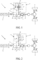
- Fig. 1 shows a layout of a vehicle comprising a transmission system in a first embodiment, which does not form part of the present invention, of the flywheel module.
- the vehicle 1 has a driving source 3 which is connected to the driven wheels 5 via a transmission system.
- the transmission system comprises a transmission 7 and a flywheel module 9 positioned between the driving source and transmission.
- the flywheel module 9 comprises a coupling unit 11 and a flywheel unit 13.
- the coupling unit comprises an input shaft 15 which is connected to the driving source , and an output shaft 17 which is connected to a first in/output 19 of the transmission 7.
- a second in/output 21 of the transmission is connected to the driven wheels 5.
- the coupling unit further comprises a first coupling 23 which comprises a first coupling half 25 connected to the input shaft, and a second coupling half 27 connected to the output shaft.
- the flywheel unit comprises an in/output 28 as well as a flywheel 29 and a reduction gear unit 31 which has an input 33 connected to the flywheel, and an output 35 which is connected to the in/output of the flywheel unit.
- the reduction gear unit comprises a reduction gearing and a coupling device connected to the reduction gearing.
- the reduction gear unit is comprised of a reduction gearing and a coupling device.
- the reduction gearing is in this case formed by a planetary gear set 37 and the coupling device by a friction brake 39.
- This planetary gear set 37 comprises three rotational members, a first rotational member of which being connected to the flywheel 29, a second rotational member being connected via a node 41 to the coupling device 11, and the third rotational member being connected to the friction brake 39.
- Fig. 2 shows a layout of a vehicle comprising a second embodiment, which does not form part of the present invention, of the flywheel module. All components that are equal to those of the first embodiment shown in Fig. 1 are designated by like reference numerals.
- This flywheel module differs from the first embodiment in that the reduction gear unit 31 comprises a gear transmission 45 and a second coupling 47 which is arranged as a friction coupling. There may even be positioned a third coupling (not shown) between the flywheel 29 and the reduction gear unit 31.
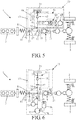
- Fig. 3 shows a layout of a vehicle comprising a third embodiment, which does not form part of the present invention, of the flywheel module. All components that are equal to those of the first embodiment shown in Fig. 1 are designated by like reference numerals.
- This flywheel module 49 comprises a further reduction gearing 51 between the in/output 28 of the flywheel unit 13 and the node 41.
- This reduction gearing 51 is formed by a further planetary gear set having three rotational members, a first rotational member of which being connected to the in/output 28, a second rotational member being connected to the node 41, and the third rotational member being connected to the firm object 53, for example the housing of the transmission system.
- the in/output 28 of the flywheel unit 13 is further connected to the first coupling half 25 of the first coupling 23 via a fourth coupling 55.
- the first coupling 23 and the fourth coupling 55 are both arranged as a friction coupling.
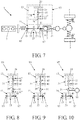
- Fig. 4 shows a layout of a vehicle comprising a fourth embodiment, which does not form part of the present invention, of the flywheel module. All components that are equal to those of the third embodiment shown in Fig. 3 are designated by like reference numerals.
- This flywheel module 57 differs from the third embodiment in that yet a fifth coupling 59 is present between the node 41 and the continuously variable transmission 7. Furthermore, the first coupling 23 and the fourth coupling 55 are both arranged as a claw coupling or synchromesh.
- Fig. 5 shows a layout of a vehicle comprising a fifth embodiment, which does not form part of the present invention, of the flywheel module. All components that are equal to those of the second embodiment shown in Fig. 2 are designated by like reference numerals.
- the third coupling 61 is positioned between the gear transmission 45 and the flywheel 29.
- the coupling device is formed by a planetary gear set 63 and a coupling support device 65, which in this embodiment is formed by an electromotor and is connected to one of the rotational members of the planetary gear set.
- a further coupling 67 (indicated in broken lines) may be positioned between two out of three rotational members of the planetary gear set 63.
- a further flywheel 69 can be connected to the reduction gearing 45 via yet another coupling 71 (also indicated in broken lines).
- Fig. 6 shows a layout of a vehicle comprising an embodiment of the flywheel module according to the invention. All components that are equal to those of the second embodiment shown in Fig. 2 are designated by like reference numerals.
- this flywheel module 73 an electrical machine in the form of an electromotor/generator 75 and a hydraulic pump 77 are connected to the node 41 and, furthermore, a hydraulic accumulator 79 is connected to the pump 77.
- the fifth coupling may also be present in the secondary shaft of the transmission 7 (designated by 81').
- the first coupling 23 is preferably a coupling that is normally closed, which is to say that if this coupling is not operated/energized, it is closed.
- the second and fifth couplings 47 and 81 are preferably normally open.
- the electromotor 75 is positioned close to the pump 77 and, furthermore, a freewheel bearing 80 is positioned between on the one hand the pump 77 and the electromotor 75 and on the other hand the node 41. Between the pump and the accumulator there is a valve 78 for shutting off and releasing the connection between the two.
- the electromotor 75 can be instrumental in bringing the pump 77 to a higher speed than the input shaft 19 of the transmission 7, so that the pump can be downsized further.
- the electromotor 75 is operated in the start-stop mode during which the hydraulic accumulator 79 is charged.
- the coupling 81 Prior to the launch of the vehicle, the coupling 81 is first to be closed and the coupling 23 to be opened. Now the vehicle can be launched on the electromotor 75 while the pressure for operating the couplings 23 and 81 and the transmission 7 is supplied by the hydraulic accumulator 79.
- the coupling 81 For starting the driving source 3 of the vehicle during driving (coupling 81 closed and coupling 23 open), the coupling 81 is operated in a slipping manner while coupling 23 is open. Subsequently, the coupling 23 is closed while the driving source 3 embodied as a combustion engine is started, after which the coupling 81 is closed completely.
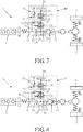
- Fig. 7 shows a further embodiment, which does not form part of the present invention, of the flywheel module.
- This flywheel module 83 comprises first coupling means 85 for coupling the input shaft 15 to the driving source 3, and second coupling means 87 for coupling the output shaft 17 to the transmission 7.
- the first and second coupling means are arranged as splines present on or in the input and output shafts 15, 17.
- Figs. 8, 9 and 10 show three variants of the flywheel module shown in Fig. 7 .
- a further reduction gearing 91 is present between the reduction gear unit 31 and the coupling unit 11.
- the second coupling 47 may then also be positioned between the reduction gearing 45 and the flywheel 29 (designated by 47') in lieu of between the two reduction gearings 45 and 49, or between the further reduction gearing 49 and the node 41 (designated by 47").
- a third coupling 95 is further positioned between the reduction gear unit 31 and the flywheel 29, and in the flywheel module 97 shown in Fig. 10 an electromotor 99 is connected to the further reduction gearing 91.
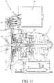
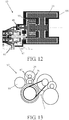
- Figs. 11 , 12 and 13 are shown concrete embodiments of the flywheel modules 89, 93 and 97 shown in Figs. 8, 9 and 10 .
- the input shaft 15 has external splines 85 and the output shaft 17 is hollow and has internal splines 87.
- the flywheel module 93 shown in Fig. 12 the flywheel 29 is located in an airtight housing 101 in which there is underpressure.
- the third coupling 95 is arranged as a magnetic coupling of which one coupling half is located inside the housing 101 and the other coupling half is located outside the housing.
- the electromotor 99 meshes with a gear present on the shaft with a gear of the further reduction gearing 91.
Landscapes
- Engineering & Computer Science (AREA)
- Mechanical Engineering (AREA)
- Transportation (AREA)
- Chemical & Material Sciences (AREA)
- Combustion & Propulsion (AREA)
- Automation & Control Theory (AREA)
- General Engineering & Computer Science (AREA)
- Arrangement Or Mounting Of Propulsion Units For Vehicles (AREA)
- Arrangement Of Transmissions (AREA)
- Retarders (AREA)
- Transmission Devices (AREA)
Applications Claiming Priority (2)
| Application Number | Priority Date | Filing Date | Title |
|---|---|---|---|
| NL2002453 | 2009-01-27 | ||
| PCT/NL2010/050039 WO2010087705A1 (en) | 2009-01-27 | 2010-01-27 | Flywheel module |
Publications (2)
| Publication Number | Publication Date |
|---|---|
| EP2391518A1 EP2391518A1 (en) | 2011-12-07 |
| EP2391518B1 true EP2391518B1 (en) | 2019-12-18 |
Family
ID=42272422
Family Applications (1)
| Application Number | Title | Priority Date | Filing Date |
|---|---|---|---|
| EP10707691.1A Active EP2391518B1 (en) | 2009-01-27 | 2010-01-27 | Flywheel module |
Country Status (6)
| Country | Link |
|---|---|
| US (1) | US20120028752A1 (enExample) |
| EP (1) | EP2391518B1 (enExample) |
| JP (1) | JP5591830B2 (enExample) |
| CN (1) | CN102395482B (enExample) |
| IN (1) | IN2011KN03522A (enExample) |
| WO (1) | WO2010087705A1 (enExample) |
Families Citing this family (23)
| Publication number | Priority date | Publication date | Assignee | Title |
|---|---|---|---|---|
| BR112013012308A2 (pt) * | 2010-11-18 | 2016-08-23 | Dti Group Bv | método de arranque e dispositivo de arranque para ligar um motor de combustão e/ou movimentar um veículo |
| EP2518369B1 (en) * | 2011-04-28 | 2015-04-22 | Volvo Car Corporation | Drive train for a vehicle and method to control a drive train for a vehicle |
| EP2581251B1 (en) | 2011-10-11 | 2018-03-28 | Dana Limited | Device and method for synchronizing a flywheel with a drivetrain |
| KR101904256B1 (ko) * | 2011-11-22 | 2018-10-05 | 디티아이 그룹 비.브이. | 연소 기관의 시동 및/또는 차량의 구동을 위한 시동 방법 및 시동 장치 |
| RU2621408C2 (ru) * | 2011-12-23 | 2017-06-05 | ДжейСи Бэмфорд Экскавейторс Лтд | Гидравлическая система с накопителем кинетической энергии |
| CN102897012B (zh) * | 2012-09-28 | 2015-09-02 | 杭州电子科技大学 | 一种基于机液联合能量再生的混合动力回路 |
| DE102013222445A1 (de) * | 2013-01-25 | 2014-07-31 | Magna Powertrain Ag & Co. Kg | Schwungmassenspeicher |
| JP2015033882A (ja) * | 2013-08-08 | 2015-02-19 | ジヤトコ株式会社 | フライホイール回生システム及びその制御方法 |
| JP5977212B2 (ja) * | 2013-08-08 | 2016-08-24 | ジヤトコ株式会社 | フライホイール回生システム及びその制御方法 |
| JP5960658B2 (ja) * | 2013-08-08 | 2016-08-02 | ジヤトコ株式会社 | フライホイール回生システム及びその制御方法 |
| FR3020321B1 (fr) * | 2014-04-24 | 2017-11-24 | Peugeot Citroen Automobiles Sa | Vehicule automobile comportant une chaine de traction hybride a moteur thermique et dispositif de stockage d'energie, et procede d'utilisation pour le demarrage du moteur thermique |
| JP2016038059A (ja) * | 2014-08-08 | 2016-03-22 | ジヤトコ株式会社 | フライホイール回生システム及びその制御方法 |
| FR3025140B1 (fr) * | 2014-08-28 | 2018-03-02 | Valeo Systemes De Controle Moteur | Systeme mecanique d'amplification de puissance. |
| DE102014114770A1 (de) * | 2014-10-13 | 2016-04-14 | Getrag Getriebe- Und Zahnradfabrik Hermann Hagenmeyer Gmbh & Cie Kg | Hydraulikanordnung für einen Kraftfahrzeug-Antriebsstrang |
| DE102014114771A1 (de) * | 2014-10-13 | 2016-04-14 | Getrag Getriebe- Und Zahnradfabrik Hermann Hagenmeyer Gmbh & Cie Kg | Kraftfahrzeug-Antriebsstrang |
| EP3064766A1 (de) * | 2015-03-03 | 2016-09-07 | MWI Micro Wave Ignition AG | Verfahren und Vorrichtung zum Einbringen von Mikrowellenenergie in einen Brennraum eines Verbrennungsmotors |
| CN104924898B (zh) * | 2015-06-23 | 2017-07-07 | 湖南江麓容大车辆传动股份有限公司 | 一种用于自动变速器的怠速启停系统 |
| CN105235492A (zh) * | 2015-11-13 | 2016-01-13 | 台州科技职业学院 | 一种节能型液压传动装置 |
| WO2017223524A1 (en) * | 2016-06-24 | 2017-12-28 | The Regents Of The University Of California | Hybrid vehicle powertrains with flywheel energy storage systems |
| HU230864B1 (hu) * | 2016-09-23 | 2018-11-29 | László Bacskó | Lendkerékhajtás kerekeken gördülő jármű folyamatos meghajtására, valamint eljárás ilyen lendkerékhajtás folyamatos működőképességének biztosításra |
| CN106734808A (zh) * | 2017-01-14 | 2017-05-31 | 江苏华威机械制造有限公司 | 一种用于电液锤主液压泵电机的飞轮蓄能装置 |
| WO2020164103A1 (en) * | 2019-02-15 | 2020-08-20 | Guangxi Liugong Machinery Co., Ltd. | Construction machine with flywheel arrangement |
| CN110341460A (zh) * | 2019-06-14 | 2019-10-18 | 浙江轩孚自动变速器有限公司 | 混合动力系统及具有该系统的车辆 |
Family Cites Families (10)
| Publication number | Priority date | Publication date | Assignee | Title |
|---|---|---|---|---|
| DE2941501C2 (de) * | 1979-10-12 | 1987-05-07 | MAN Technologie GmbH, 8000 München | Antriebsvorrichtung für Fahrzeuge mit instationärer Betriebsweise, insbesondere für Kraftfahrzeuge |
| DE3026219A1 (de) * | 1980-07-10 | 1982-02-18 | Voith Getriebe Kg, 7920 Heidenheim | Antriebsaggregat mit einer antriebsmaschine und einem schwungrad |
| US4583505A (en) * | 1984-09-17 | 1986-04-22 | Aisin Seiki Kabushiki Kaisha | Continuously charged flywheel type power delivery system |
| JP3744414B2 (ja) * | 2001-11-29 | 2006-02-08 | トヨタ自動車株式会社 | 車両の制御装置 |
| US6978860B2 (en) * | 2004-04-01 | 2005-12-27 | Delphi Technologies, Inc. | Method and system for electric power steering |
| NL1028800C2 (nl) * | 2004-10-20 | 2006-04-24 | Dti Group Bv | Aandrijving en transmissie-module met voor een voertuig aangepaste lay-out. |
| GB2440996A (en) * | 2006-05-25 | 2008-02-20 | Powertrain Technology Ltd | Power transmission system |
| JP4078658B1 (ja) * | 2007-03-20 | 2008-04-23 | 博光 多田 | 惰力利用による燃料節約走行車両 |
| WO2009010819A1 (en) * | 2007-07-17 | 2009-01-22 | Renault Trucks | Powertrain comprising an optimized energy recovery system |
| JP5310530B2 (ja) * | 2009-03-19 | 2013-10-09 | アイシン・エィ・ダブリュ株式会社 | 自動変速機の油圧制御装置 |
-
2010
- 2010-01-27 IN IN3522KON2011 patent/IN2011KN03522A/en unknown
- 2010-01-27 US US13/146,262 patent/US20120028752A1/en not_active Abandoned
- 2010-01-27 EP EP10707691.1A patent/EP2391518B1/en active Active
- 2010-01-27 CN CN201080014104.8A patent/CN102395482B/zh not_active Expired - Fee Related
- 2010-01-27 JP JP2011547841A patent/JP5591830B2/ja not_active Expired - Fee Related
- 2010-01-27 WO PCT/NL2010/050039 patent/WO2010087705A1/en not_active Ceased
Non-Patent Citations (1)
| Title |
|---|
| None * |
Also Published As
| Publication number | Publication date |
|---|---|
| IN2011KN03522A (enExample) | 2015-07-10 |
| US20120028752A1 (en) | 2012-02-02 |
| EP2391518A1 (en) | 2011-12-07 |
| JP2012516417A (ja) | 2012-07-19 |
| CN102395482A (zh) | 2012-03-28 |
| WO2010087705A1 (en) | 2010-08-05 |
| JP5591830B2 (ja) | 2014-09-17 |
| CN102395482B (zh) | 2016-02-10 |
Similar Documents
| Publication | Publication Date | Title |
|---|---|---|
| EP2391518B1 (en) | Flywheel module | |
| CN105383278B (zh) | 具有发动机起动和再生制动模式的动力总成 | |
| US8608615B2 (en) | Drive system, in particular for a motor vehicle | |
| CN102582623B (zh) | 机动车动力系的摩擦起动策略 | |
| US8894526B2 (en) | Powertrain for a hybrid electric vehicle | |
| KR101628147B1 (ko) | 차량용 변속장치 | |
| CN107107733B (zh) | 混合动力车辆的自动传动装置和混合动力车辆的控制方法 | |
| US10647192B2 (en) | Hybrid power system | |
| EP2351661A1 (en) | Hybrid power driving system and gear position operation method thereof | |
| US20090156351A1 (en) | Hybrid transmission | |
| US20120270691A1 (en) | Multi-mode electric drive hybrid transmission | |
| EP2374647A1 (en) | Dual gear train driving structure at input side of basin-type gear | |
| RU2011139839A (ru) | Силовая передача для гибридного транспортного средства | |
| PL1776251T3 (pl) | Sekwencje uruchomienia i działania silnika hybrydowego pojazdów | |
| JP2012516417A5 (enExample) | ||
| JP2010083230A (ja) | ハイブリッド駆動装置 | |
| CN203557942U (zh) | 具有内燃发动机和起动机发电机的机动车辆的动力传动系 | |
| CA2828252A1 (en) | Electric motor assist for transmission electric oil pump | |
| US20180244143A1 (en) | Hybrid Drive for a Hybrid Vehicle | |
| CN105697135A (zh) | 用于内燃机的压缩机装置以及内燃机 | |
| US9770968B2 (en) | Flywheel module | |
| JP2010083231A (ja) | ハイブリッド駆動装置 | |
| JP2010126072A (ja) | ハイブリッド電気自動車の制御装置 | |
| CN107921868B (zh) | 用于混合动力推进车辆的传动系统 | |
| KR20230063571A (ko) | 차량의 하이브리드 파워트레인 |
Legal Events
| Date | Code | Title | Description |
|---|---|---|---|
| PUAI | Public reference made under article 153(3) epc to a published international application that has entered the european phase |
Free format text: ORIGINAL CODE: 0009012 |
|
| 17P | Request for examination filed |
Effective date: 20110829 |
|
| AK | Designated contracting states |
Kind code of ref document: A1 Designated state(s): AT BE BG CH CY CZ DE DK EE ES FI FR GB GR HR HU IE IS IT LI LT LU LV MC MK MT NL NO PL PT RO SE SI SK SM TR |
|
| DAX | Request for extension of the european patent (deleted) | ||
| RIN1 | Information on inventor provided before grant (corrected) |
Inventor name: VROEMEN, BAS GERARD Inventor name: SERRARENS, ALEXANDER FRANCISCUS ANITA Inventor name: VAN DRUTEN, ROELL MARIE |
|
| STAA | Information on the status of an ep patent application or granted ep patent |
Free format text: STATUS: EXAMINATION IS IN PROGRESS |
|
| 17Q | First examination report despatched |
Effective date: 20161215 |
|
| GRAP | Despatch of communication of intention to grant a patent |
Free format text: ORIGINAL CODE: EPIDOSNIGR1 |
|
| STAA | Information on the status of an ep patent application or granted ep patent |
Free format text: STATUS: GRANT OF PATENT IS INTENDED |
|
| INTG | Intention to grant announced |
Effective date: 20190109 |
|
| RIN1 | Information on inventor provided before grant (corrected) |
Inventor name: VROEMEN, BAS GERARD Inventor name: VAN DRUTEN, ROELL MARIE Inventor name: SERRARENS, ALEXANDER FRANCISCUS ANITA |
|
| RIC1 | Information provided on ipc code assigned before grant |
Ipc: B60W 30/18 20120101ALI20100823BHEP Ipc: B60K 6/365 20071001ALI20100823BHEP Ipc: B60K 6/10 20060101AFI20100823BHEP Ipc: B60K 6/387 20071001ALI20100823BHEP Ipc: B60W 10/02 20060101ALI20100823BHEP Ipc: B60K 6/12 20060101ALI20100823BHEP Ipc: B60K 6/543 20071001ALI20100823BHEP |
|
| GRAJ | Information related to disapproval of communication of intention to grant by the applicant or resumption of examination proceedings by the epo deleted |
Free format text: ORIGINAL CODE: EPIDOSDIGR1 |
|
| STAA | Information on the status of an ep patent application or granted ep patent |
Free format text: STATUS: EXAMINATION IS IN PROGRESS |
|
| INTC | Intention to grant announced (deleted) | ||
| GRAP | Despatch of communication of intention to grant a patent |
Free format text: ORIGINAL CODE: EPIDOSNIGR1 |
|
| STAA | Information on the status of an ep patent application or granted ep patent |
Free format text: STATUS: GRANT OF PATENT IS INTENDED |
|
| INTG | Intention to grant announced |
Effective date: 20190710 |
|
| RIN1 | Information on inventor provided before grant (corrected) |
Inventor name: VAN DRUTEN, ROELL MARIE Inventor name: VROEMEN, BAS GERARD Inventor name: SERRARENS, ALEXANDER FRANCISCUS ANITA |
|
| GRAS | Grant fee paid |
Free format text: ORIGINAL CODE: EPIDOSNIGR3 |
|
| GRAA | (expected) grant |
Free format text: ORIGINAL CODE: 0009210 |
|
| STAA | Information on the status of an ep patent application or granted ep patent |
Free format text: STATUS: THE PATENT HAS BEEN GRANTED |
|
| RIN1 | Information on inventor provided before grant (corrected) |
Inventor name: VAN DRUTEN, ROELL MARIE Inventor name: VROEMEN, BAS GERARD Inventor name: SERRARENS, ALEXANDER FRANCISCUS ANITA |
|
| AK | Designated contracting states |
Kind code of ref document: B1 Designated state(s): AT BE BG CH CY CZ DE DK EE ES FI FR GB GR HR HU IE IS IT LI LT LU LV MC MK MT NL NO PL PT RO SE SI SK SM TR |
|
| REG | Reference to a national code |
Ref country code: GB Ref legal event code: FG4D |
|
| REG | Reference to a national code |
Ref country code: CH Ref legal event code: EP |
|
| REG | Reference to a national code |
Ref country code: IE Ref legal event code: FG4D |
|
| REG | Reference to a national code |
Ref country code: DE Ref legal event code: R096 Ref document number: 602010062411 Country of ref document: DE |
|
| REG | Reference to a national code |
Ref country code: AT Ref legal event code: REF Ref document number: 1214189 Country of ref document: AT Kind code of ref document: T Effective date: 20200115 |
|
| REG | Reference to a national code |
Ref country code: NL Ref legal event code: MP Effective date: 20191218 |
|
| PG25 | Lapsed in a contracting state [announced via postgrant information from national office to epo] |
Ref country code: GR Free format text: LAPSE BECAUSE OF FAILURE TO SUBMIT A TRANSLATION OF THE DESCRIPTION OR TO PAY THE FEE WITHIN THE PRESCRIBED TIME-LIMIT Effective date: 20200319 Ref country code: LT Free format text: LAPSE BECAUSE OF FAILURE TO SUBMIT A TRANSLATION OF THE DESCRIPTION OR TO PAY THE FEE WITHIN THE PRESCRIBED TIME-LIMIT Effective date: 20191218 Ref country code: NO Free format text: LAPSE BECAUSE OF FAILURE TO SUBMIT A TRANSLATION OF THE DESCRIPTION OR TO PAY THE FEE WITHIN THE PRESCRIBED TIME-LIMIT Effective date: 20200318 Ref country code: LV Free format text: LAPSE BECAUSE OF FAILURE TO SUBMIT A TRANSLATION OF THE DESCRIPTION OR TO PAY THE FEE WITHIN THE PRESCRIBED TIME-LIMIT Effective date: 20191218 Ref country code: SE Free format text: LAPSE BECAUSE OF FAILURE TO SUBMIT A TRANSLATION OF THE DESCRIPTION OR TO PAY THE FEE WITHIN THE PRESCRIBED TIME-LIMIT Effective date: 20191218 Ref country code: BG Free format text: LAPSE BECAUSE OF FAILURE TO SUBMIT A TRANSLATION OF THE DESCRIPTION OR TO PAY THE FEE WITHIN THE PRESCRIBED TIME-LIMIT Effective date: 20200318 Ref country code: FI Free format text: LAPSE BECAUSE OF FAILURE TO SUBMIT A TRANSLATION OF THE DESCRIPTION OR TO PAY THE FEE WITHIN THE PRESCRIBED TIME-LIMIT Effective date: 20191218 |
|
| PGFP | Annual fee paid to national office [announced via postgrant information from national office to epo] |
Ref country code: DE Payment date: 20200121 Year of fee payment: 11 Ref country code: IT Payment date: 20200227 Year of fee payment: 11 Ref country code: GB Payment date: 20200124 Year of fee payment: 11 |
|
| REG | Reference to a national code |
Ref country code: LT Ref legal event code: MG4D |
|
| PG25 | Lapsed in a contracting state [announced via postgrant information from national office to epo] |
Ref country code: HR Free format text: LAPSE BECAUSE OF FAILURE TO SUBMIT A TRANSLATION OF THE DESCRIPTION OR TO PAY THE FEE WITHIN THE PRESCRIBED TIME-LIMIT Effective date: 20191218 |
|
| PGFP | Annual fee paid to national office [announced via postgrant information from national office to epo] |
Ref country code: BE Payment date: 20200121 Year of fee payment: 11 |
|
| PGFP | Annual fee paid to national office [announced via postgrant information from national office to epo] |
Ref country code: FR Payment date: 20200121 Year of fee payment: 11 |
|
| PG25 | Lapsed in a contracting state [announced via postgrant information from national office to epo] |
Ref country code: RO Free format text: LAPSE BECAUSE OF FAILURE TO SUBMIT A TRANSLATION OF THE DESCRIPTION OR TO PAY THE FEE WITHIN THE PRESCRIBED TIME-LIMIT Effective date: 20191218 Ref country code: CZ Free format text: LAPSE BECAUSE OF FAILURE TO SUBMIT A TRANSLATION OF THE DESCRIPTION OR TO PAY THE FEE WITHIN THE PRESCRIBED TIME-LIMIT Effective date: 20191218 Ref country code: PT Free format text: LAPSE BECAUSE OF FAILURE TO SUBMIT A TRANSLATION OF THE DESCRIPTION OR TO PAY THE FEE WITHIN THE PRESCRIBED TIME-LIMIT Effective date: 20200513 Ref country code: EE Free format text: LAPSE BECAUSE OF FAILURE TO SUBMIT A TRANSLATION OF THE DESCRIPTION OR TO PAY THE FEE WITHIN THE PRESCRIBED TIME-LIMIT Effective date: 20191218 Ref country code: NL Free format text: LAPSE BECAUSE OF FAILURE TO SUBMIT A TRANSLATION OF THE DESCRIPTION OR TO PAY THE FEE WITHIN THE PRESCRIBED TIME-LIMIT Effective date: 20191218 |
|
| PG25 | Lapsed in a contracting state [announced via postgrant information from national office to epo] |
Ref country code: SM Free format text: LAPSE BECAUSE OF FAILURE TO SUBMIT A TRANSLATION OF THE DESCRIPTION OR TO PAY THE FEE WITHIN THE PRESCRIBED TIME-LIMIT Effective date: 20191218 Ref country code: SK Free format text: LAPSE BECAUSE OF FAILURE TO SUBMIT A TRANSLATION OF THE DESCRIPTION OR TO PAY THE FEE WITHIN THE PRESCRIBED TIME-LIMIT Effective date: 20191218 Ref country code: IS Free format text: LAPSE BECAUSE OF FAILURE TO SUBMIT A TRANSLATION OF THE DESCRIPTION OR TO PAY THE FEE WITHIN THE PRESCRIBED TIME-LIMIT Effective date: 20200418 |
|
| REG | Reference to a national code |
Ref country code: CH Ref legal event code: PL |
|
| REG | Reference to a national code |
Ref country code: DE Ref legal event code: R097 Ref document number: 602010062411 Country of ref document: DE |
|
| PG25 | Lapsed in a contracting state [announced via postgrant information from national office to epo] |
Ref country code: MC Free format text: LAPSE BECAUSE OF FAILURE TO SUBMIT A TRANSLATION OF THE DESCRIPTION OR TO PAY THE FEE WITHIN THE PRESCRIBED TIME-LIMIT Effective date: 20191218 |
|
| REG | Reference to a national code |
Ref country code: AT Ref legal event code: MK05 Ref document number: 1214189 Country of ref document: AT Kind code of ref document: T Effective date: 20191218 |
|
| PLBE | No opposition filed within time limit |
Free format text: ORIGINAL CODE: 0009261 |
|
| STAA | Information on the status of an ep patent application or granted ep patent |
Free format text: STATUS: NO OPPOSITION FILED WITHIN TIME LIMIT |
|
| PG25 | Lapsed in a contracting state [announced via postgrant information from national office to epo] |
Ref country code: LU Free format text: LAPSE BECAUSE OF NON-PAYMENT OF DUE FEES Effective date: 20200127 Ref country code: DK Free format text: LAPSE BECAUSE OF FAILURE TO SUBMIT A TRANSLATION OF THE DESCRIPTION OR TO PAY THE FEE WITHIN THE PRESCRIBED TIME-LIMIT Effective date: 20191218 Ref country code: ES Free format text: LAPSE BECAUSE OF FAILURE TO SUBMIT A TRANSLATION OF THE DESCRIPTION OR TO PAY THE FEE WITHIN THE PRESCRIBED TIME-LIMIT Effective date: 20191218 |
|
| 26N | No opposition filed |
Effective date: 20200921 |
|
| PG25 | Lapsed in a contracting state [announced via postgrant information from national office to epo] |
Ref country code: LI Free format text: LAPSE BECAUSE OF NON-PAYMENT OF DUE FEES Effective date: 20200131 Ref country code: CH Free format text: LAPSE BECAUSE OF NON-PAYMENT OF DUE FEES Effective date: 20200131 Ref country code: AT Free format text: LAPSE BECAUSE OF FAILURE TO SUBMIT A TRANSLATION OF THE DESCRIPTION OR TO PAY THE FEE WITHIN THE PRESCRIBED TIME-LIMIT Effective date: 20191218 Ref country code: SI Free format text: LAPSE BECAUSE OF FAILURE TO SUBMIT A TRANSLATION OF THE DESCRIPTION OR TO PAY THE FEE WITHIN THE PRESCRIBED TIME-LIMIT Effective date: 20191218 |
|
| PG25 | Lapsed in a contracting state [announced via postgrant information from national office to epo] |
Ref country code: IE Free format text: LAPSE BECAUSE OF NON-PAYMENT OF DUE FEES Effective date: 20200127 |
|
| PG25 | Lapsed in a contracting state [announced via postgrant information from national office to epo] |
Ref country code: PL Free format text: LAPSE BECAUSE OF FAILURE TO SUBMIT A TRANSLATION OF THE DESCRIPTION OR TO PAY THE FEE WITHIN THE PRESCRIBED TIME-LIMIT Effective date: 20191218 |
|
| REG | Reference to a national code |
Ref country code: DE Ref legal event code: R119 Ref document number: 602010062411 Country of ref document: DE |
|
| GBPC | Gb: european patent ceased through non-payment of renewal fee |
Effective date: 20210127 |
|
| REG | Reference to a national code |
Ref country code: BE Ref legal event code: MM Effective date: 20210131 |
|
| PG25 | Lapsed in a contracting state [announced via postgrant information from national office to epo] |
Ref country code: FR Free format text: LAPSE BECAUSE OF NON-PAYMENT OF DUE FEES Effective date: 20210131 |
|
| PG25 | Lapsed in a contracting state [announced via postgrant information from national office to epo] |
Ref country code: GB Free format text: LAPSE BECAUSE OF NON-PAYMENT OF DUE FEES Effective date: 20210127 Ref country code: DE Free format text: LAPSE BECAUSE OF NON-PAYMENT OF DUE FEES Effective date: 20210803 |
|
| PG25 | Lapsed in a contracting state [announced via postgrant information from national office to epo] |
Ref country code: IT Free format text: LAPSE BECAUSE OF NON-PAYMENT OF DUE FEES Effective date: 20210127 |
|
| PG25 | Lapsed in a contracting state [announced via postgrant information from national office to epo] |
Ref country code: TR Free format text: LAPSE BECAUSE OF FAILURE TO SUBMIT A TRANSLATION OF THE DESCRIPTION OR TO PAY THE FEE WITHIN THE PRESCRIBED TIME-LIMIT Effective date: 20191218 Ref country code: MT Free format text: LAPSE BECAUSE OF FAILURE TO SUBMIT A TRANSLATION OF THE DESCRIPTION OR TO PAY THE FEE WITHIN THE PRESCRIBED TIME-LIMIT Effective date: 20191218 Ref country code: CY Free format text: LAPSE BECAUSE OF FAILURE TO SUBMIT A TRANSLATION OF THE DESCRIPTION OR TO PAY THE FEE WITHIN THE PRESCRIBED TIME-LIMIT Effective date: 20191218 |
|
| PG25 | Lapsed in a contracting state [announced via postgrant information from national office to epo] |
Ref country code: MK Free format text: LAPSE BECAUSE OF FAILURE TO SUBMIT A TRANSLATION OF THE DESCRIPTION OR TO PAY THE FEE WITHIN THE PRESCRIBED TIME-LIMIT Effective date: 20191218 |
|
| PG25 | Lapsed in a contracting state [announced via postgrant information from national office to epo] |
Ref country code: BE Free format text: LAPSE BECAUSE OF NON-PAYMENT OF DUE FEES Effective date: 20210131 |